

Page 1

AUDIO A/D CONVERTER BOARD
BKPF-L751
MAINTENANCE MANUAL
1st Edition
Serial No. 10001 and Higher
Page 2

! WARNING
This manual is intended for qualified service personnel only.
To reduce the risk of electric shock, fire or injury, do not perform any servicing other than that
contained in the operating instructions unless you are qualified to do so. Refer all servicing to
qualified service personnel.
! WARNUNG
Die Anleitung ist nur für qualifiziertes Fachpersonal bestimmt.
Alle Wartungsarbeiten dürfen nur von qualifiziertem Fachpersonal ausgeführt werden. Um die
Gefahr eines elektrischen Schlages, Feuergefahr und Verletzungen zu vermeiden, sind bei
Wartungsarbeiten strikt die Angaben in der Anleitung zu befolgen. Andere als die angegeben
Wartungsarbeiten dürfen nur von Personen ausgeführt werden, die eine spezielle Befähigung
dazu besitzen.
! AVERTISSEMENT
Ce manual est destiné uniquement aux personnes compétentes en charge de l’entretien. Afin
de réduire les risques de décharge électrique, d’incendie ou de blessure n’effectuer que les
réparations indiquées dans le mode d’emploi à moins d’être qualifié pour en effectuer d’autres.
Pour toute réparation faire appel à une personne compétente uniquement.
BKPF-L751
Page 3

Table of Contents
Manual Structure
Purpose of this manual ........................................................................................ 3 (E)
Contents ............................................................................................................... 3 (E)
Related manuals................................................................................................... 3 (E)
1. Service Overview
1-1. Notes on Repair Parts............................................................................1-1 (E)
1-2. IC Link Replacement ............................................................................1-1 (E)
1-3. Name and Function of Switch/Indicator/etc. ........................................1-2 (E)
2. Electrical Alignment
2-1. Electrical Alignment Overview.............................................................2-1 (E)
2-1-1. Required Equipment and Tools............................................2-1 (E)
2-1-2. Connection ...........................................................................2-1 (E)
2-2. Preparation for Adjustment ...................................................................2-2 (E)
2-3. +5 V Power Supply Voltage Adjustment .............................................2-2 (E)
2-4. Word-clock Frequency Adjustment ......................................................2-3 (E)
2-5. Input/Output Gain Adjustment..............................................................2-3 (E)
2-6. CMRR (Common Mode Rejection Ratio) Adjustment.........................2-4 (E)
BKPF-L751
3. Spare Parts
ADC-40 ..................................................................................................................3-1
CN-1857/1858 ........................................................................................................3-5
4. Semiconductor Pin Assignments
5. Block Diagram
OVERALL .............................................................................................................5-1
1 (E)
Page 4

6. Schematic Diagrams
ADC-40 ..................................................................................................................6-2
CN-1857/1858 ........................................................................................................6-8
7. Board Layouts
ADC-40 ..................................................................................................................7-1
CN-1857 ................................................................................................................. 7-2
2 (E)
BKPF-L751
Page 5

Purpose of this manual
Contents
Manual Structure
This manual is the maintenance manual of Audio A/D Converter Board
BKPF-L751.
This manual is intended for use by trained system and service engineers, and
describes the information for periodic maintenance and detailed service.
This manual is organized by following sections.
Section 1 Service Overview
This section explains the notes on repair parts and IC link replacement.
Section 2 Electrical Alignment
This section explains the adjustment after replacing part.
Section 3 Spare Parts
This section describes the spare parts.
Related manuals
Section 4 Semiconductor Pin Assignments
This section describes the pin assignments of semiconductor.
Section 5 Block Diagram
This section describes the overall block diagram.
Section 6 Schematic Diagrams
This section describes the schematic diagrams of the ADC-40 and CN-1857/1858
boards.
Section 7 Board Layouts
This section describes the board layouts for the ADC-40 and CN-1857 boards.
The following manual is prepared for this unit.
..
. Installation Manual (Supplied with BKPF-L751)
..
This manual describes the information on BKPF-L751 installing.
BKPF-L751
3 (E)
Page 6

Page 7

Section 1
Service Overview
1-1. Notes on Repair Parts
1. Safety Related Components Warning
w
Components marked ! are critical to safe operation.
Therefore, specified parts should be used in the case of
replacement.
2. Standardization of Parts
Some repair parts supplied by Sony differ from those
used for the unit. These are because of parts commonality and improvement.
Parts list has the present standardized repair parts.
3. Stock of Parts
Parts marked with “o” at SP (Supply code) column of
the spare parts list may not be stocked. Therefore, the
delivery date will be delayed.
4. Units Representation
The following represented units are changed or
omitted in writing.
1-2. IC Link Replacement
w
An IC link is critical parts to safe operation.
Replace this component with Sony parts whose part
numbers appear in this manual published by Sony.
If not, this may cause a fire or electric shock.
Be sure to use the specified component in this manual.
The IC link is mounted on the ADC-40 board. Be sure to
replace with the specified IC link as shown below after
removing the foreign substances that may cause the shorts.
ADC-40 Board
Ref No. (Address) Description Part No.
PS1 (K-3) IC link 2 A !1-533-282-21
Units Representation
Capacitance uFuF
Inductance uHuH
Resistance Z Abbreviation
n
For the replacement of the ADC-40 board, please buy
BKPF-L751 because ADC-40 mounted circuit board is not
prepared for spare parts.
BKPF-L751
1-1 (E)
Page 8
1-3. Name and Function of Switch/Indicator1-3. Name and Function of Switch/Indicator1-3. Name and Function of Switch/Indicator/etc.
1-3. Name and Function of Switch/Indicator/etc.
!= ![
!\1
!;!]
2
3
5
7
9
!-
4
6
8
0
D808
D807
D809
ON
S401
RV405
ON
S402
RV406
ON
S403
RV407
ON
S404
RV408
NORMAL
S705
VIDEO
SWAP
WORD
SYNG
S5
NORMAL
S1
HIGH
S4
S3
OFF ON
HDNTSC
PAL
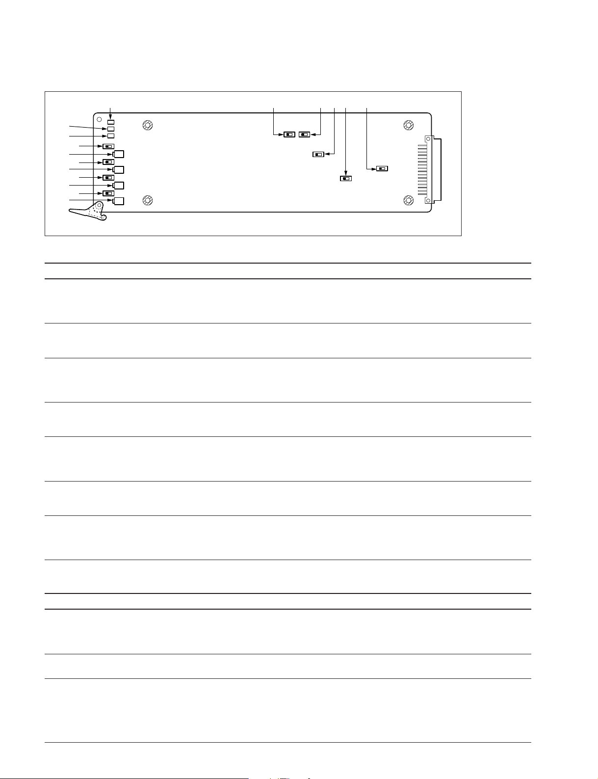
Main Board (ADC-40 Board: Side A)
Switches/gain adjusting VRs (Factory default settings are indicated by a
\\
\ mark)
\\
No. Ref. No. Name Function
!] S1 WORD SYNC SELECT Selects the output level of the regenerated-word-clock signal output to the REF VIDEO/
WORD CLOCK (OUT) connector.
\ NORMAL: 1 V p-p
HIGH: 2.8 V p-p (using the traditional digital audio models)
!; S3 75 Z 75 Z termination ON/OFF switch for the REF VIDEO/WORD CLOCK IN connector.
\ OFF: When using the loop-through connection
ON: Otherwise
!\ S4 VIDEO SELECT Selects the signal method of the video reference input signal.
(Valid only when S5 is set to VIDEO.)
\ NTSC PAL: NTSC or PAL method
HD: HD method
Section 2
Electrical Alignment
2-1. Electrical Alignment Overview
2-1-1. Required Equipment and Tools
Use the equipment listed below or the equivalent.
Item Model Remarks
Extension board EX-668 (Part No. A-8318-552-A) For PFV-L1
EX-731 (Part No. A-8322-598-A) For PFV-L10
Analog audio signal generator * Tektronix SG505 (Option 02)
Audio level meter * —
Interface unit Sony PFV-L1 or PFV-L10
Audio D/A convertor board * Sony BKPF-L752 Factory default condition
Digital voltmetor * —
Frequency counter * Advantest TR5821AK
Oscilloscope * Tectronix 2465B
Adjustment screwdriver — Insulation type
Terminator — BNC type (feed-through), 75 Z
Resister (600 Z, within 1 %) with lead
*: Use the equipment after calibration has been completed.
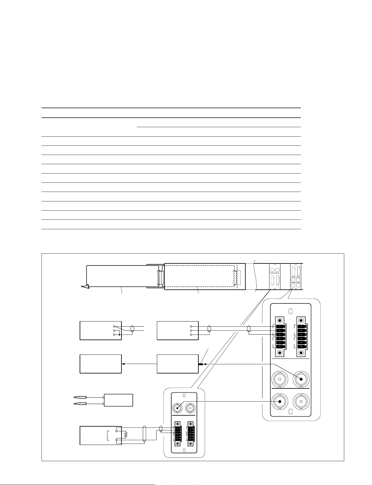
2-1-2. Connection
BKPF-L751
(At CMRR adjustment)
Frequency counter
Audio level mater
Input
ADC-40 board
Analog audio signal generator
(At Gain adjustment)
+
_
COM
Input
Digital voltmeter
+
_
+
600 Z
_
Extension board EX-668/731
+
_
COM
Terminator
Oscilloscope
CH2
OUT
CH2
IN
BKPF-L752
AES/EBU IN
12
AUDIO OUT
+
+
_
_
123
G
G
+
+
_
_
4
G
G
PFV-L1/L10 (Rear)PFV-L1/L10 (Side)
AUDIO
IN
+
_
1
G
+
_
2
G
REF VIDEO
/WORD CLOCK
IN (OUT)
AES/EBU
*1 *2
OUT
BKPF-L751
+
_
3
G
+
_
4
G
L751
BKPF-L751
L752
2-1 (E)
Page 10
2-2. Preparation for Adjustment
2-3. +5 V Power Supply Voltage Adjustment
2-2. Preparation for Adjustment
1. Remove the connector panel of the BKPF-L751.
2. Write down the customer setting of the switch S1
(LOOP/WORD switch) on the CN-1857 board of the
connector panel in following table.
3. Extend the ADC-40 board with a extension board.
4. Write down the customer settings of each switch on
the ADC-40 board in following table.
5. Set the switches on the CN-1857 and ADC-40 boards
as follows:
Board Ref. No. Setting at adj. Customer
(Address) setting
CN-1857 S1 WORD CLK OUT
ADC-40 S1 (H-2) NORMAL
S3 (K-2) ON
S4 (J-3) NTSC PAL
S5 (G-1) VIDEO
S401 (A-1) ON
S402 (A-2) ON
S403 (A-2) ON
S404 (A-3) ON
S705 (G-1) NORMAL
2-3.
++
+5 V Power Supply Voltage
++
Adjustment
Measuring equipment: Digital voltmeter
1. Set the digital voltmeter as follows:
Range: AUTO
Mode: DC V
++
+5 V adjustment for Digital line
++
2. Connect the probe of the digital voltmeter as follows:
+: TP1/ADC-40 (J-3)
_: E1/ADC-40 (C-1)
3. Adjust the voltage on the digital voltmeter.
Adjustment point: 1RV1/ADC-40 (J-3)
Specification: 4.81 ±0.05 V dc
++
+5 V adjustment for Analog line
++
4. Connect the probe of the digital voltmeter as follows:
+: TP2/ADC-40 (G-3)
_: E10/ADC-40 (G-2)
5. Adjust the voltage.
Adjustment point: 1RV2/ADC-40 (G-3)
Specification: 4.81 ±0.05 V dc
6. Reattach the connector panel of the BKPF-L751.
7. Install the audio D/A convertor board (BKPF-L752 in
a factory default condition) to the interface unit.
Factory default condition of BKPF-L752.
. DIP switch (S3/DAC-38 board): All OFFs
. Adjust VRs (RV101, 201, 301, 401/DAC-38):
Each VR was completed the adjustment so as to
convert a _20 dB FS to +4.0 dBm.
8. Turn on the power of equipment, and warm up them
for about ten minutes.
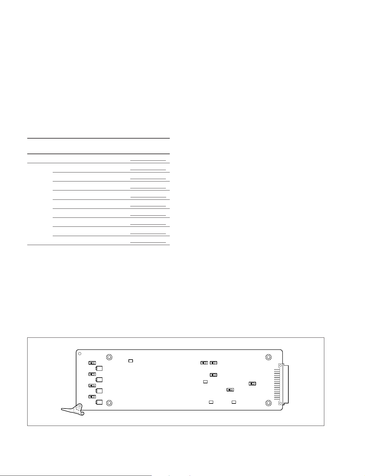
E1
S401
S402
S403
S404
ON
ON
ON
ON
1 RV401
RV405
1 RV402
RV406
1 RV403
RV407
1 RV404
RV408
n
When adjusting the power supply voltage, be sure to
perform Sections 2-4 and later.
WORD
VIDEO
SYNG
NORMAL
SWAP
S5
S705
S1
NORMAL
E10
RV1000 1
HIGH 0-5V
S4
PAL
TP2 TP1
S3
OFF ON
HDNTSC
1 RV11 RV2
2-2 (E)
ADC-40 Board (Side A)
BKPF-L751
Page 11
2-4. Word-clock Frequency Adjustment
2-5. Input/Output Gain Adjustment
2-4. Word-clock Frequency Adjustment
Measuring equipment: Oscilloscope and Frequency counter
1. Connect the oscilloscope’s CH2 output to the frequency counter.
2. Connect the oscilloscope’s CH2 input to the REF
VIDEO/WORD CLOCK (OUT) connector.
2. Set the oscilloscope as follows:
CH2: DC 500 mV/DIV
TIME: 5 us/DIV
TRIG: CH2, + slope
Band limit: ON
3. Adjust the frequency on the frequency counter.
Adjustment point: 1RV1000/ADC-40 (G-2)
Specification: 48,000 ±48 Hz
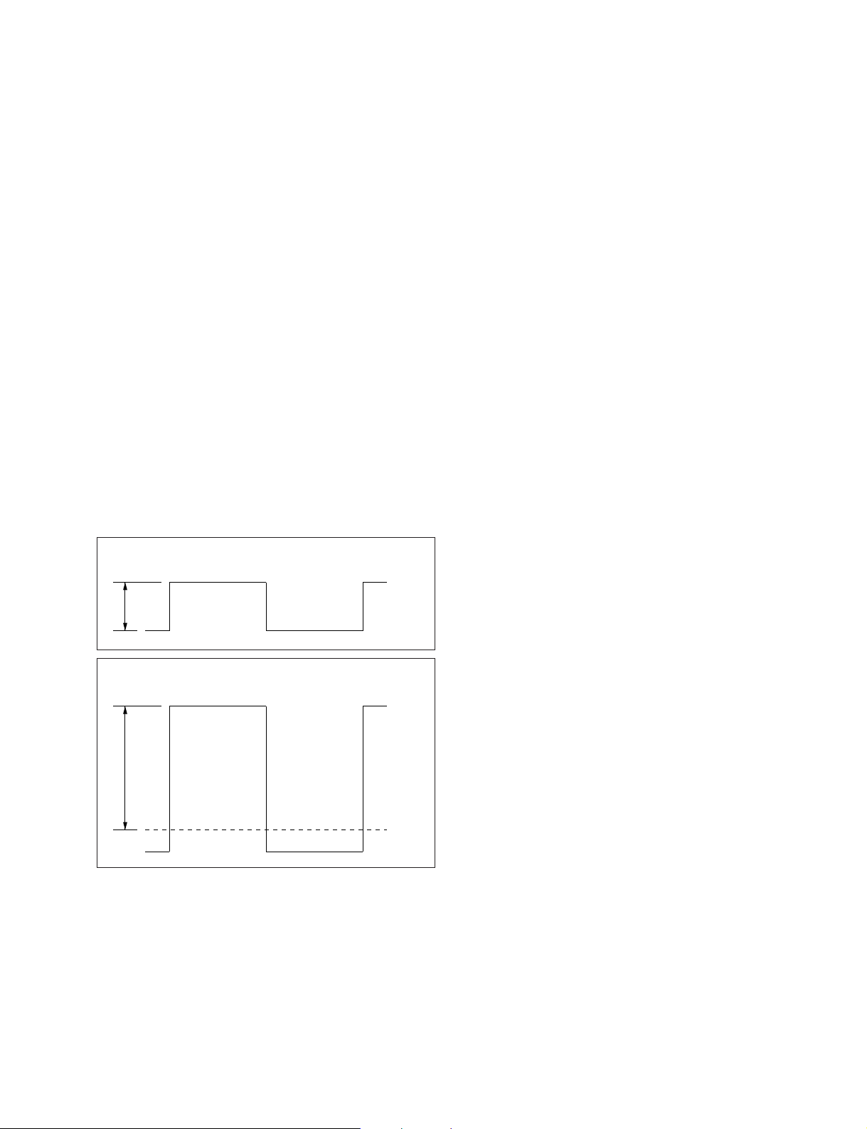
4. Check the level on the oscilloscope with a 75 Z
terminator.
When the S1/ADC-40 (H-2) is set to NORMAL:
Specification: A = 1.0 ±0.1 V p-p
When the S1/ADC-40 (H-2) is set to HIGH 0-5V:
Specification: B > 2.4 V dc
S1 : NORMAL
A
2-5. Input/Output Gain Adjustment
Measuring equipment: Audio level meter
1. Set the analog audio signal generator to +4.0 dBm,
1 kHz.
CH1/2 adjustment
2. Connect the generator to the CH1 input of AUDIO IN
connector.
3. Connect the AES/EBU IN1 connector of the audio
D/A converter board (BKPF-L752) to the AES/EBU
OUT1 connector.
4. Connect the audio level meter to the CH1 output of
AUDIO OUT connector of the audio D/A converter
board (BKPF-L752).
5. Adjust the CH1 output level on the audio level meter.
Adjustment point: 1RV405/ADC-40 (A-1)
Specification: 4.0 ±0.1 dBm (at 600 Z load)
6. Connect the generator to the CH2 input of AUDIO IN
connector.
7. Connect the audio level meter to the CH2 output of
AUDIO OUT connector of the audio D/A converter
board (BKPF-L752).
8. Adjust the CH2 output level.
Adjustment point: 1RV406/ADC-40 (A-2)
Specification: 4.0 ±0.1 dBm (at 600 Z load)
S1 : HIGH
B
BKPF-L751
0 Vdc
(GND)
CH3/4 adjustment
9. Connect the generator to the CH3 input of AUDIO IN
connector.
10. Connect the AES/EBU IN2 connector of the audio
D/A converter board (BKPF-L752) to the AES/EBU
OUT2 connector.
11. Connect the audio level meter to the CH3 output of
AUDIO OUT connector of the audio D/A converter
board (BKPF-L752).
12. Adjust the CH3 output level.
Adjustment point: 1RV407/ADC-40 (A-3)
Specification: 4.0 ±0.1 dBm (at 600 Z load)
13. Connect the generator to the CH4 input of AUDIO IN
connector.
14. Connect the audio level meter to the CH4 output of
AUDIO OUT connector of the audio D/A converter
board (BKPF-L752).
15. Adjust the CH4 output level.
Adjustment point: 1RV408/ADC-40 (A-3)
Specification: 4.0 ±0.1 dBm (at 600 Z load)
n
0 dBm = 0.755 Vrms
2-3 (E)
Page 12

2-6. CMRR (Common Mode Rejection Ratio) Adjustment
2-6. CMRR (Common Mode Rejection
Ratio) Adjustment
Measuring equipment: Audio level meter
1. Set the analog audio signal generator to +18.0 dBm,
60 Hz.
Refer to Section 2-1-2 for the connection.
CH1/2 adjustment
2. Connect the generator to the CH1 input of AUDIO IN
connector.
3. Connect the AES/EBU IN1 connector of the audio
D/A converter board (BKPF-L752) to the AES/EBU
OUT1 connector.
4. Connect the audio level meter to the CH1 output of
AUDIO OUT connector of the audio D/A converter
board (BKPF-L752).
5. Adjust the CH1 output level on the audio level meter.
Adjustment point: 1RV401/ADC-40 (A-1)
Specification: Minimum (_65 dBm or less)
6. Connect the generator to the CH2 input of AUDIO IN
connector.
7. Connect the audio level meter to the CH2 output of
AUDIO OUT connector of the audio D/A converter
board (BKPF-L752).
8. Adjust the CH2 output level.
Adjustment point: 1RV402/ADC-40 (A-2)
Specification: Minimum (_65 dBm or less)
CH3/4 adjustment
9. Connect the generator to the CH3 input of AUDIO IN
connector.
10. Connect the AES/EBU IN2 connector of the audio
D/A converter board (BKPF-L752) to the AES/EBU
OUT2 connector.
11. Connect the audio level meter to the CH3 output of
AUDIO OUT connector of the audio D/A converter
board (BKPF-L752).
12. Adjust the CH3 output level.
Adjustment point: 1RV403/ADC-40 (A-2)
Specification: Minimum (_65 dBm or less)
13. Connect the generator to the CH4 input of AUDIO IN
connector..
14. Connect the audio level meter to the CH4 output of
AUDIO OUT connector of the audio D/A converter
board (BKPF-L752).
15. Adjust the CH4 output level.
Adjustment point: 1RV404/ADC-40 (A-3)
Specification: Minimum (_65 dBm or less)
16. After turning off the power, reset the switches on the
CN-1857 and ADC-40 boards to the customer settings.
2-4 (E)
n
0 dBm = 0.775 Vrms
BKPF-L751
Page 13

Section 3
Spare Parts
-----------ADC-40 BOARD
----------- Ref. No.
or Q'ty Part No. SP Description
1pc 3-179-084-01 s LEVER (R), PC BOARD
or 3-179-085-01 s LEVER (L), PC BOARD
2pcs 7-685-547-14 s SCREW +BTP 3x10
C401 1-104-608-11 s ELECT, CHIP 33uF 20% 6.3V
C402 1-104-608-11 s ELECT, CHIP 33uF 20% 6.3V
C403 1-104-608-11 s ELECT, CHIP 33uF 20% 6.3V
C404 1-104-608-11 s ELECT, CHIP 33uF 20% 6.3V
C405 1-163-243-11 s CERAMIC, CHIP 47pF 5% 50V (2012)
C406 1-163-243-11 s CERAMIC, CHIP 47pF 5% 50V (2012)
C407 1-163-243-11 s CERAMIC, CHIP 47pF 5% 50V (2012)
C408 1-163-243-11 s CERAMIC, CHIP 47pF 5% 50V (2012)
C409 1-104-608-11 s ELECT, CHIP 33uF 20% 6.3V
C410 1-104-608-11 s ELECT, CHIP 33uF 20% 6.3V
C411 1-104-608-11 s ELECT, CHIP 33uF 20% 6.3V
C412 1-104-608-11 s ELECT, CHIP 33uF 20% 6.3V
C413 1-126-393-11 s ELECT, CHIP 33uF 20% 10V
C414 1-126-393-11 s ELECT, CHIP 33uF 20% 10V
C415 1-126-393-11 s ELECT, CHIP 33uF 20% 10V
C416 1-126-393-11 s ELECT, CHIP 33uF 20% 10V
C417 1-115-154-11 s ELECT, CHIP 10uF 20% 16V
C418 1-115-154-11 s ELECT, CHIP 10uF 20% 16V
C419 1-115-154-11 s ELECT, CHIP 10uF 20% 16V
C420 1-115-154-11 s ELECT, CHIP 10uF 20% 16V
C421 1-104-608-11 s ELECT, CHIP 33uF 20% 6.3V
C422 1-104-608-11 s ELECT, CHIP 33uF 20% 6.3V
C423 1-104-608-11 s ELECT, CHIP 33uF 20% 6.3V
C424 1-104-608-11 s ELECT, CHIP 33uF 20% 6.3V
C425 1-104-608-11 s ELECT, CHIP 33uF 20% 6.3V
C426 1-104-608-11 s ELECT, CHIP 33uF 20% 6.3V
C427 1-104-608-11 s ELECT, CHIP 33uF 20% 6.3V
C428 1-104-608-11 s ELECT, CHIP 33uF 20% 6.3V
C429 1-163-011-11 s CERAMIC, CHIP 1500pF 10% 50V (2012)
C430 1-163-011-11 s CERAMIC, CHIP 1500pF 10% 50V (2012)
C431 1-163-011-11 s CERAMIC, CHIP 1500pF 10% 50V (2012)
C432 1-163-011-11 s CERAMIC, CHIP 1500pF 10% 50V (2012)
C504 1-128-416-11 s ELECT, CHIP 100uF 20% 16V
C505 1-126-394-11 s ELECT, CHIP 10uF 20% 16V
C506 1-163-038-00 s CERAMIC, CHIP 0.1uF 25V (2012)
C507 1-163-038-00 s CERAMIC, CHIP 0.1uF 25V (2012)
C508 1-126-394-11 s ELECT, CHIP 10uF 20% 16V
C509 1-115-340-11 s CERAMIC, CHIP 0.22uF 10% 25V (2012)
C510 1-126-394-11 s ELECT, CHIP 10uF 20% 16V
C511 1-163-038-00 s CERAMIC, CHIP 0.1uF 25V (2012)
C512 1-115-340-11 s CERAMIC, CHIP 0.22uF 10% 25V (2012)
C513 1-126-394-11 s ELECT, CHIP 10uF 20% 16V
C514 1-163-038-00 s CERAMIC, CHIP 0.1uF 25V (2012)
C515 1-126-394-11 s ELECT, CHIP 10uF 20% 16V
C516 1-163-038-00 s CERAMIC, CHIP 0.1uF 25V (2012)
C517 1-163-038-00 s CERAMIC, CHIP 0.1uF 25V (2012)
C519 1-115-340-11 s CERAMIC, CHIP 0.22uF 10% 25V (2012)
C520 1-126-394-11 s ELECT, CHIP 10uF 20% 16V
C521 1-163-038-00 s CERAMIC, CHIP 0.1uF 25V (2012)
C522 1-115-340-11 s CERAMIC, CHIP 0.22uF 10% 25V (2012)
C523 1-126-394-11 s ELECT, CHIP 10uF 20% 16V
C524 1-163-038-00 s CERAMIC, CHIP 0.1uF 25V (2012)
C525 1-163-038-00 s CERAMIC, CHIP 0.1uF 25V (2012)
C526 1-163-038-00 s CERAMIC, CHIP 0.1uF 25V (2012)
(ADC-40 BOARD)
Ref. No.
or Q'ty Part No. SP Description
C527 1-163-038-00 s CERAMIC, CHIP 0.1uF 25V (2012)
C528 1-163-038-00 s CERAMIC, CHIP 0.1uF 25V (2012)
C606 1-163-220-11 s CERAMIC, CHIP 3pF 50V (2012)
C607 1-163-113-00 s CERAMIC, CHIP 68pF 5% 50V (2012)
C608 1-163-038-00 s CERAMIC, CHIP 0.1uF 25V (2012)
C609 1-163-220-11 s CERAMIC, CHIP 3pF 50V (2012)
C610 1-126-393-11 s ELECT, CHIP 33uF 20% 10V
C611 1-164-346-11 s CERAMIC, CHIP 1.0uF 16V (2012)
C612 1-164-346-11 s CERAMIC, CHIP 1.0uF 16V (2012)
C614 1-163-220-11 s CERAMIC, CHIP 3pF 50V (2012)
C615 1-163-113-00 s CERAMIC, CHIP 68pF 5% 50V (2012)
C616 1-163-038-00 s CERAMIC, CHIP 0.1uF 25V (2012)
C617 1-163-220-11 s CERAMIC, CHIP 3pF 50V (2012)
C618 1-126-393-11 s ELECT, CHIP 33uF 20% 10V
C619 1-164-346-11 s CERAMIC, CHIP 1.0uF 16V (2012)
C620 1-164-346-11 s CERAMIC, CHIP 1.0uF 16V (2012)
C623 1-164-346-11 s CERAMIC, CHIP 1.0uF 16V (2012)
C624 1-164-346-11 s CERAMIC, CHIP 1.0uF 16V (2012)
C625 1-164-346-11 s CERAMIC, CHIP 1.0uF 16V (2012)
C627 1-164-346-11 s CERAMIC, CHIP 1.0uF 16V (2012)
C712 1-163-038-00 s CERAMIC, CHIP 0.1uF 25V (2012)
C713 1-163-038-00 s CERAMIC, CHIP 0.1uF 25V (2012)
C714 1-163-038-00 s CERAMIC, CHIP 0.1uF 25V (2012)
C715 1-163-038-00 s CERAMIC, CHIP 0.1uF 25V (2012)
C716 1-163-038-00 s CERAMIC, CHIP 0.1uF 25V (2012)
C720 1-126-396-11 s ELECT, CHIP 47uF 20% 16V
C721 1-164-004-11 s CERAMIC, CHIP 0.1uF 10% 25V (2012)
C724 1-163-251-11 s CERAMIC, CHIP 100pF 5% 50V (2012)
C725 1-137-193-11 s FILM 0.39uF 5% 50V
C726 1-163-021-11 s CERAMIC, CHIP 0.01uF 10% 50V (2012)
C727 1-164-004-11 s CERAMIC, CHIP 0.1uF 10% 25V (2012)
C728 1-163-038-00 s CERAMIC, CHIP 0.1uF 25V (2012)
C729 1-163-038-00 s CERAMIC, CHIP 0.1uF 25V (2012)
C730 1-163-038-00 s CERAMIC, CHIP 0.1uF 25V (2012)
C803 1-163-038-00 s CERAMIC, CHIP 0.1uF 25V (2012)
C806 1-115-340-11 s CERAMIC, CHIP 0.22uF 10% 25V (2012)
C807 1-165-319-11 s CERAMIC, CHIP 0.1uF 50V (2012)
C808 1-165-319-11 s CERAMIC, CHIP 0.1uF 50V (2012)
C809 1-165-319-11 s CERAMIC, CHIP 0.1uF 50V (2012)
C810 1-128-400-11 s ELECT 47uF 20% 25V
C901 1-109-892-11 s ELECT, CHIP 47uF 20% 25V
C902 1-163-038-00 s CERAMIC, CHIP 0.1uF 25V (2012)
C903 1-126-392-11 s ELECT, CHIP 100uF 20% 6.3V
C904 1-126-392-11 s ELECT, CHIP 100uF 20% 6.3V
C905 1-163-038-00 s CERAMIC, CHIP 0.1uF 25V (2012)
C907 1-126-401-11 s ELECT, CHIP 1.0uF 20% 50V
C909 1-109-892-11 s ELECT, CHIP 47uF 20% 25V
C911 1-128-391-11 s ELECT, CHIP 330uF 20% 6.3V
C914 1-128-391-11 s ELECT, CHIP 330uF 20% 6.3V
C915 1-163-038-00 s CERAMIC, CHIP 0.1uF 25V (2012)
C916 1-163-038-00 s CERAMIC, CHIP 0.1uF 25V (2012)
C917 1-163-038-00 s CERAMIC, CHIP 0.1uF 25V (2012)
C918 1-163-038-00 s CERAMIC, CHIP 0.1uF 25V (2012)
C919 1-115-154-11 s ELECT, CHIP 10uF 20% 16V
C920 1-163-085-00 s CERAMIC, CHIP 2pF 50V (2012)
C921 1-163-239-11 s CERAMIC, CHIP 33pF 5% 50V (2012)
C922 1-164-346-11 s CERAMIC, CHIP 1.0uF 16V (2012)
BKPF-L751
3-1
Page 14

(ADC-40 BOARD)
(ADC-40 BOARD)
Ref. No.
or Q'ty Part No. SP Description
C925 1-117-145-11 s ELECT, CHIP 1.0uF 20% 50V
C926 1-117-145-11 s ELECT, CHIP 1.0uF 20% 50V
C927 1-126-394-11 s ELECT, CHIP 10uF 20% 16V
C928 1-126-394-11 s ELECT, CHIP 10uF 20% 16V
C930 1-126-394-11 s ELECT, CHIP 10uF 20% 16V
C931 1-126-396-11 s ELECT, CHIP 47uF 20% 16V
C932 1-126-396-11 s ELECT, CHIP 47uF 20% 16V
C934 1-126-396-11 s ELECT, CHIP 47uF 20% 16V
C935 1-126-396-11 s ELECT, CHIP 47uF 20% 16V
C936 1-126-396-11 s ELECT, CHIP 47uF 20% 16V
C939 1-164-346-11 s CERAMIC, CHIP 1.0uF 16V (2012)
C1000 1-164-346-11 s CERAMIC, CHIP 1.0uF 16V (2012)
C1001 1-126-392-11 s ELECT, CHIP 100uF 20% 6.3V
Ref. No.
or Q'ty Part No. SP Description
FL1 1-239-895-11 s FILTER, EMI, CHIP (2012)
FL2 1-239-895-11 s FILTER, EMI, CHIP (2012)
FL3 1-239-895-11 s FILTER, EMI, CHIP (2012)
FL4 1-239-895-11 s FILTER, EMI, CHIP (2012)
FL5 1-239-895-11 s FILTER, EMI, CHIP (2012)
FL6 1-239-895-11 s FILTER, EMI, CHIP (2012)
FL7 1-239-895-11 s FILTER, EMI, CHIP (2012)
FL8 1-239-895-11 s FILTER, EMI, CHIP (2012)
FL9 1-239-898-22 s FILTER, EMI, CHIP (2012)
FL10 1-239-898-22 s FILTER, EMI, CHIP (2012)
FL502 1-233-313-31 s FILTER, EMI, CHIP (3225)
FL503 1-233-313-31 s FILTER, EMI, CHIP (3225)
FL702 1-233-313-31 s FILTER, EMI, CHIP (3225)
C1002 1-164-346-11 s CERAMIC, CHIP 1.0uF 16V (2012)
C1003 1-163-231-11 s CERAMIC, CHIP 15pF 5% 50V (2012)
IC401 8-759-700-96 s IC NJM5534M
IC402 8-759-700-96 s IC NJM5534M
C1004 1-163-113-00 s CERAMIC, CHIP 68pF 5% 50V (2012)
C1005 1-164-346-11 s CERAMIC, CHIP 1.0uF 16V (2012)
C1006 1-163-243-11 s CERAMIC, CHIP 47pF 5% 50V (2012)
IC403 8-759-700-96 s IC NJM5534M
IC404 8-759-700-96 s IC NJM5534M
IC405 8-759-700-94 s IC NJM5532M
C1007 1-163-133-00 s CERAMIC, CHIP 470pF 5% 50V (2012)
C1011 1-163-239-11 s CERAMIC, CHIP 33pF 5% 50V (2012)
IC406 8-759-700-94 s IC NJM5532M
IC407 8-759-700-94 s IC NJM5532M
C1014 1-164-346-11 s CERAMIC, CHIP 1.0uF 16V (2012)
C1015 1-164-346-11 s CERAMIC, CHIP 1.0uF 16V (2012)
C1016 1-163-038-00 s CERAMIC, CHIP 0.1uF 25V (2012)
IC408 8-759-700-94 s IC NJM5532M
IC501 8-759-578-44 s IC AK5392-VS
IC502 8-759-578-44 s IC AK5392-VS
C1017 1-163-038-00 s CERAMIC, CHIP 0.1uF 25V (2012)
C1019 1-164-346-11 s CERAMIC, CHIP 1.0uF 16V (2012)
IC504 8-759-327-60 s IC TC7W125FU
IC508 8-759-388-62 s IC NJU7062M
C1020 1-126-392-11 s ELECT, CHIP 100uF 20% 6.3V
C1021 1-164-346-11 s CERAMIC, CHIP 1.0uF 16V (2012)
C1023 1-163-275-11 s CERAMIC, CHIP 1000pF 5% 50V (2012)
IC509 8-759-388-62 s IC NJU7062M
IC510 8-759-327-60 s IC TC7W125FU
IC602 8-759-062-88 s IC CXD8277Q
C1024 1-163-038-00 s CERAMIC, CHIP 0.1uF 25V (2012)
C1025 1-164-346-11 s CERAMIC, CHIP 1.0uF 16V (2012)
IC603 8-759-062-88 s IC CXD8277Q
IC605 8-759-447-19 s IC AD8041AR
C1026 1-164-346-11 s CERAMIC, CHIP 1.0uF 16V (2012)
C1027 1-164-346-11 s CERAMIC, CHIP 1.0uF 16V (2012)
C1028 1-163-243-11 s CERAMIC, CHIP 47pF 5% 50V (2012)
IC607 8-759-447-19 s IC AD8041AR
IC608 8-759-492-38 s IC LM2941CSX
IC609 8-759-492-38 s IC LM2941CSX
C1029 1-163-038-00 s CERAMIC, CHIP 0.1uF 25V (2012)
C1030 1-163-275-11 s CERAMIC, CHIP 1000pF 5% 50V (2012)
IC610 8-759-258-42 s IC LT1253CS8
IC611 8-759-394-69 s IC NJM311M
C1031 1-163-113-00 s CERAMIC, CHIP 68pF 5% 50V (2012)
C1032 1-163-231-11 s CERAMIC, CHIP 15pF 5% 50V (2012)
C1033 1-115-339-11 s CERAMIC, CHIP 0.1uF 10% 50V (2012)
IC612 8-759-271-04 s IC LT1252CS8
IC701 8-759-594-97 o IC 9572-ADC40-V1.00, PLD
IC702 8-759-990-63 s IC PCF8574AT
C1034 1-115-339-11 s CERAMIC, CHIP 0.1uF 10% 50V (2012)
C1036 1-115-339-11 s CERAMIC, CHIP 0.1uF 10% 50V (2012)
IC703 8-759-459-26 s IC TC5081BP
IC704 8-759-437-39 s IC MB3771PF
CN1 1-506-746-11 s CONNECTOR, DIN 48P, MALE
CN2 1-785-584-11 s PIN, CONNECTOR 6P
IC706 8-759-327-60 s IC TC7W125FU
IC707 8-759-327-60 s IC TC7W125FU
IC708 8-759-989-91 s IC TL7705ACPS
D1 8-719-821-58 s DIODE 1SS271L
D401 8-719-941-09 s DIODE DAP202U
D402 8-719-941-09 s DIODE DAP202U
D403 8-719-941-09 s DIODE DAP202U
D404 8-719-941-09 s DIODE DAP202U
IC712 8-759-985-17 s IC 74AC04SJ
IC802 8-759-987-27 s IC LM1881M
IC803 8-759-242-64 s IC TC4W53F
IC804 8-759-239-55 s IC TC74HC123AF
IC805 8-759-188-77 s IC RN5RG36AA
D502 8-719-800-76 s DIODE 1SS226
D503 8-719-800-76 s DIODE 1SS226
D504 8-719-800-76 s DIODE 1SS226
D505 8-719-800-76 s DIODE 1SS226
D506 8-719-800-76 s DIODE 1SS226
IC806 8-759-710-78 s IC NJM082BM
IC807 8-759-710-78 s IC NJM082BM
IC810 8-759-082-55 s IC TC7W00FU
IC811 8-759-985-26 s IC 74AC74SJ
D806 8-719-975-40 s DIODE RB411D
D807 8-719-027-84 s LED CL-155UR/G-D, RED/GRN
D808 8-719-027-84 s LED CL-155UR/G-D, RED/GRN
D809 8-719-027-84 s LED CL-155UR/G-D, RED/GRN
L1 1-424-643-11 s COIL, CHOKE 10uH
L2 1-424-643-11 s COIL, CHOKE 10uH
L3 1-424-643-11 s COIL, CHOKE 10uH
L4 1-403-659-11 s INDUCTOR, CHIP 0.01uH (1608)
D900 8-719-800-76 s DIODE 1SS226
L302 1-410-393-11 s INDUCTOR, CHIP 100uH (3225)
D901 8-719-801-78 s DIODE 1SS184
L601 1-410-377-31 s INDUCTOR, CHIP 4.7uH (3225)
D902 8-719-041-39 s DIODE KV1470
DD601 1-475-610-11 s CONVERTER UNIT, DC-DC
3-2
BKPF-L751
Page 15

(ADC-40 BOARD)
(ADC-40 BOARD)
Ref. No.
or Q'ty Part No. SP Description
L602 1-410-377-31 s INDUCTOR, CHIP 4.7uH (3225)
L603 1-410-730-11 s INDUCTOR, CHIP 0.12uH (3225)
L605 1-410-730-11 s INDUCTOR, CHIP 0.12uH (3225)
Ref. No.
or Q'ty Part No. SP Description
R413 1-216-646-11 s METAL, CHIP 620 0.5% 1/10W (2012)
R414 1-216-646-11 s METAL, CHIP 620 0.5% 1/10W (2012)
R415 1-216-646-11 s METAL, CHIP 620 0.5% 1/10W (2012)
R416 1-216-646-11 s METAL, CHIP 620 0.5% 1/10W (2012)
PS1 ! 1-533-282-21 s LINK, IC, CHIP 2A
Q701 8-729-802-80 s TRANSISTOR 2SC3661
Q900 8-729-113-22 s TRANSISTOR FA1L4L-L30
Q901 8-729-120-28 s TRANSISTOR 2SC1623-L5L6
Q902 8-729-216-22 s TRANSISTOR 2SA1162-G
Q903 8-729-216-22 s TRANSISTOR 2SA1162-G
Q904 8-729-120-28 s TRANSISTOR 2SC1623-L5L6
Q905 8-729-203-32 s TRANSISTOR 2SJ106BL
Q906 8-729-203-32 s TRANSISTOR 2SJ106BL
Q907 8-729-203-32 s TRANSISTOR 2SJ106BL
R417 1-218-367-11 s METAL, CHIP 10K 0.1% 1/16W (2012)
R418 1-218-367-11 s METAL, CHIP 10K 0.1% 1/16W (2012)
R419 1-218-367-11 s METAL, CHIP 10K 0.1% 1/16W (2012)
R420 1-218-367-11 s METAL, CHIP 10K 0.1% 1/16W (2012)
R421 1-218-367-11 s METAL, CHIP 10K 0.1% 1/16W (2012)
R422 1-218-367-11 s METAL, CHIP 10K 0.1% 1/16W (2012)
R423 1-218-367-11 s METAL, CHIP 10K 0.1% 1/16W (2012)
R424 1-218-367-11 s METAL, CHIP 10K 0.1% 1/16W (2012)
R429 1-216-603-11 s METAL, CHIP 10 0.5% 1/10W (2012)
R430 1-216-611-11 s METAL, CHIP 22 0.5% 1/10W (2012)
R431 1-216-603-11 s METAL, CHIP 10 0.5% 1/10W (2012)
R16 1-216-651-11 s METAL, CHIP 1.0K 0.5% 1/10W (2012)
R17 1-216-659-11 s METAL, CHIP 2.2K 0.5% 1/10W (2012)
R18 1-216-645-11 s METAL, CHIP 560 0.5% 1/10W (2012)
R19 1-216-651-11 s METAL, CHIP 1.0K 0.5% 1/10W (2012)
R20 1-216-659-11 s METAL, CHIP 2.2K 0.5% 1/10W (2012)
R432 1-216-611-11 s METAL, CHIP 22 0.5% 1/10W (2012)
R433 1-216-603-11 s METAL, CHIP 10 0.5% 1/10W (2012)
R434 1-216-611-11 s METAL, CHIP 22 0.5% 1/10W (2012)
R435 1-216-603-11 s METAL, CHIP 10 0.5% 1/10W (2012)
R436 1-216-611-11 s METAL, CHIP 22 0.5% 1/10W (2012)
R21 1-216-645-11 s METAL, CHIP 560 0.5% 1/10W (2012)
R22 1-216-699-11 s METAL, CHIP 100K 0.5% 1/10W (2012)
R23 1-216-651-11 s METAL, CHIP 1.0K 0.5% 1/10W (2012)
R24 1-216-651-11 s METAL, CHIP 1.0K 0.5% 1/10W (2012)
R25 1-216-683-11 s METAL, CHIP 22K 0.5% 1/10W (2012)
R437 1-216-603-11 s METAL, CHIP 10 0.5% 1/10W (2012)
R438 1-216-603-11 s METAL, CHIP 10 0.5% 1/10W (2012)
R439 1-216-603-11 s METAL, CHIP 10 0.5% 1/10W (2012)
R440 1-216-603-11 s METAL, CHIP 10 0.5% 1/10W (2012)
R441 1-216-655-11 s METAL, CHIP 1.5K 0.5% 1/10W (2012)
R26 1-216-679-11 s METAL, CHIP 15K 0.5% 1/10W (2012)
R27 1-216-627-11 s METAL, CHIP 100 0.5% 1/10W (2012)
R28 1-216-615-11 s METAL, CHIP 33 0.5% 1/10W (2012)
R29 1-216-615-11 s METAL, CHIP 33 0.5% 1/10W (2012)
R30 1-216-699-11 s METAL, CHIP 100K 0.5% 1/10W (2012)
R442 1-216-655-11 s METAL, CHIP 1.5K 0.5% 1/10W (2012)
R443 1-216-655-11 s METAL, CHIP 1.5K 0.5% 1/10W (2012)
R444 1-216-655-11 s METAL, CHIP 1.5K 0.5% 1/10W (2012)
R445 1-216-663-11 s METAL, CHIP 3.3K 0.5% 1/10W (2012)
R446 1-216-663-11 s METAL, CHIP 3.3K 0.5% 1/10W (2012)
R31 1-216-683-11 s METAL, CHIP 22K 0.5% 1/10W (2012)
R32 1-216-683-11 s METAL, CHIP 22K 0.5% 1/10W (2012)
R33 1-216-647-11 s METAL, CHIP 680 0.5% 1/10W (2012)
R34 1-216-656-11 s METAL, CHIP 1.6K 0.5% 1/10W (2012)
R35 1-216-651-11 s METAL, CHIP 1.0K 0.5% 1/10W (2012)
R447 1-216-663-11 s METAL, CHIP 3.3K 0.5% 1/10W (2012)
R448 1-216-663-11 s METAL, CHIP 3.3K 0.5% 1/10W (2012)
R449 1-216-603-11 s METAL, CHIP 10 0.5% 1/10W (2012)
R450 1-216-611-11 s METAL, CHIP 22 0.5% 1/10W (2012)
R451 1-216-603-11 s METAL, CHIP 10 0.5% 1/10W (2012)
R36 1-216-603-11 s METAL, CHIP 10 0.5% 1/10W (2012)
R37 1-216-603-11 s METAL, CHIP 10 0.5% 1/10W (2012)
R38 1-216-683-11 s METAL, CHIP 22K 0.5% 1/10W (2012)
R39 1-216-624-11 s METAL, CHIP 75 0.5% 1/10W (2012)
R40 1-216-653-11 s METAL, CHIP 1.2K 0.5% 1/10W (2012)
R452 1-216-611-11 s METAL, CHIP 22 0.5% 1/10W (2012)
R453 1-216-603-11 s METAL, CHIP 10 0.5% 1/10W (2012)
R454 1-216-611-11 s METAL, CHIP 22 0.5% 1/10W (2012)
R455 1-216-603-11 s METAL, CHIP 10 0.5% 1/10W (2012)
R456 1-216-611-11 s METAL, CHIP 22 0.5% 1/10W (2012)
R41 1-216-671-11 s METAL, CHIP 6.8K 0.5% 1/10W (2012)
R42 1-216-665-11 s METAL, CHIP 3.9K 0.5% 1/10W (2012)
R43 1-216-659-11 s METAL, CHIP 2.2K 0.5% 1/10W (2012)
R44 1-218-768-11 s METAL, CHIP 470K 0.5% 1/10W (2012)
R45 1-216-651-11 s METAL, CHIP 1.0K 0.5% 1/10W (2012)
R457 1-216-663-11 s METAL, CHIP 3.3K 0.5% 1/10W (2012)
R458 1-216-663-11 s METAL, CHIP 3.3K 0.5% 1/10W (2012)
R459 1-216-663-11 s METAL, CHIP 3.3K 0.5% 1/10W (2012)
R460 1-216-663-11 s METAL, CHIP 3.3K 0.5% 1/10W (2012)
R461 1-220-751-11 s METAL, CHIP 2.2K 0.1% 1/10W (2012)
R47 1-216-691-11 s METAL, CHIP 47K 0.5% 1/10W (2012)
R48 1-216-606-11 s METAL, CHIP 13 0.5% 1/10W (2012)
R49 1-216-622-11 s METAL, CHIP 62 0.5% 1/10W (2012)
R401 1-216-646-11 s METAL, CHIP 620 0.5% 1/10W (2012)
R402 1-216-646-11 s METAL, CHIP 620 0.5% 1/10W (2012)
R462 1-220-751-11 s METAL, CHIP 2.2K 0.1% 1/10W (2012)
R463 1-220-751-11 s METAL, CHIP 2.2K 0.1% 1/10W (2012)
R464 1-220-751-11 s METAL, CHIP 2.2K 0.1% 1/10W (2012)
R465 1-220-751-11 s METAL, CHIP 2.2K 0.1% 1/10W (2012)
R466 1-220-751-11 s METAL, CHIP 2.2K 0.1% 1/10W (2012)
R403 1-216-646-11 s METAL, CHIP 620 0.5% 1/10W (2012)
R404 1-216-646-11 s METAL, CHIP 620 0.5% 1/10W (2012)
R405 1-216-646-11 s METAL, CHIP 620 0.5% 1/10W (2012)
R406 1-216-646-11 s METAL, CHIP 620 0.5% 1/10W (2012)
R407 1-216-646-11 s METAL, CHIP 620 0.5% 1/10W (2012)
R467 1-220-751-11 s METAL, CHIP 2.2K 0.1% 1/10W (2012)
R468 1-220-751-11 s METAL, CHIP 2.2K 0.1% 1/10W (2012)
R469 1-216-639-11 s METAL, CHIP 330 0.5% 1/10W (2012)
R470 1-216-639-11 s METAL, CHIP 330 0.5% 1/10W (2012)
R471 1-216-639-11 s METAL, CHIP 330 0.5% 1/10W (2012)
R408 1-216-646-11 s METAL, CHIP 620 0.5% 1/10W (2012)
R409 1-216-646-11 s METAL, CHIP 620 0.5% 1/10W (2012)
R410 1-216-646-11 s METAL, CHIP 620 0.5% 1/10W (2012)
R411 1-216-646-11 s METAL, CHIP 620 0.5% 1/10W (2012)
R412 1-216-646-11 s METAL, CHIP 620 0.5% 1/10W (2012)
R472 1-216-639-11 s METAL, CHIP 330 0.5% 1/10W (2012)
R473 1-216-639-11 s METAL, CHIP 330 0.5% 1/10W (2012)
R474 1-216-639-11 s METAL, CHIP 330 0.5% 1/10W (2012)
R475 1-216-639-11 s METAL, CHIP 330 0.5% 1/10W (2012)
BKPF-L751
3-3
Page 16

(ADC-40 BOARD)
(ADC-40 BOARD)
Ref. No.
or Q'ty Part No. SP Description
R476 1-216-639-11 s METAL, CHIP 330 0.5% 1/10W (2012)
R477 1-216-683-11 s METAL, CHIP 22K 0.5% 1/10W (2012)
R478 1-216-655-11 s METAL, CHIP 1.5K 0.5% 1/10W (2012)
R479 1-216-655-11 s METAL, CHIP 1.5K 0.5% 1/10W (2012)
R480 1-216-655-11 s METAL, CHIP 1.5K 0.5% 1/10W (2012)
R481 1-216-655-11 s METAL, CHIP 1.5K 0.5% 1/10W (2012)
R482 1-216-682-11 s METAL, CHIP 20K 0.5% 1/10W (2012)
R491 1-216-615-11 s METAL, CHIP 33 0.5% 1/10W (2012)
(S/N 10001 to 10270)
R492 1-216-615-11 s METAL, CHIP 33 0.5% 1/10W (2012)
Ref. No.
or Q'ty Part No. SP Description
R801 1-216-699-11 s METAL, CHIP 100K 0.5% 1/10W (2012)
R802 1-216-699-11 s METAL, CHIP 100K 0.5% 1/10W (2012)
R803 1-216-699-11 s METAL, CHIP 100K 0.5% 1/10W (2012)
R804 1-216-699-11 s METAL, CHIP 100K 0.5% 1/10W (2012)
R805 1-216-699-11 s METAL, CHIP 100K 0.5% 1/10W (2012)
R806 1-216-699-11 s METAL, CHIP 100K 0.5% 1/10W (2012)
R807 1-216-675-11 s METAL, CHIP 10K 0.5% 1/10W (2012)
R808 1-216-675-11 s METAL, CHIP 10K 0.5% 1/10W (2012)
R810 1-216-698-11 s METAL, CHIP 91K 0.5% 1/10W (2012)
R811 1-216-682-11 s METAL, CHIP 20K 0.5% 1/10W (2012)
(S/N 10001 to 10270)
R493 1-216-615-11 s METAL, CHIP 33 0.5% 1/10W (2012)
(S/N 10001 to 10270)
R812 1-216-682-11 s METAL, CHIP 20K 0.5% 1/10W (2012)
R813 1-216-682-11 s METAL, CHIP 20K 0.5% 1/10W (2012)
R814 1-216-668-11 s METAL, CHIP 5.1K 0.5% 1/10W (2012)
R494 1-216-615-11 s METAL, CHIP 33 0.5% 1/10W (2012)
(S/N 10001 to 10250)
R815 1-216-651-11 s METAL, CHIP 1.0K 0.5% 1/10W (2012)
R816 1-216-647-11 s METAL, CHIP 680 0.5% 1/10W (2012)
R502 1-216-627-11 s METAL, CHIP 100 0.5% 1/10W (2012)
R503 1-216-603-11 s METAL, CHIP 10 0.5% 1/10W (2012)
R504 1-216-611-11 s METAL, CHIP 22 0.5% 1/10W (2012)
R506 1-216-603-11 s METAL, CHIP 10 0.5% 1/10W (2012)
R817 1-216-675-11 s METAL, CHIP 10K 0.5% 1/10W (2012)
R818 1-216-651-11 s METAL, CHIP 1.0K 0.5% 1/10W (2012)
R819 1-216-651-11 s METAL, CHIP 1.0K 0.5% 1/10W (2012)
R820 1-216-651-11 s METAL, CHIP 1.0K 0.5% 1/10W (2012)
R507 1-216-627-11 s METAL, CHIP 100 0.5% 1/10W (2012)
R821 1-216-675-11 s METAL, CHIP 10K 0.5% 1/10W (2012)
R509 1-216-651-11 s METAL, CHIP 1.0K 0.5% 1/10W (2012)
R510 1-216-651-11 s METAL, CHIP 1.0K 0.5% 1/10W (2012)
R511 1-216-627-11 s METAL, CHIP 100 0.5% 1/10W (2012)
R512 1-216-627-11 s METAL, CHIP 100 0.5% 1/10W (2012)
R822 1-216-611-11 s METAL, CHIP 22 0.5% 1/10W (2012)
R823 1-216-639-11 s METAL, CHIP 330 0.5% 1/10W (2012)
R824 1-216-639-11 s METAL, CHIP 330 0.5% 1/10W (2012)
R825 1-216-675-11 s METAL, CHIP 10K 0.5% 1/10W (2012)
R513 1-216-651-11 s METAL, CHIP 1.0K 0.5% 1/10W (2012)
R826 1-216-639-11 s METAL, CHIP 330 0.5% 1/10W (2012)
R514 1-216-651-11 s METAL, CHIP 1.0K 0.5% 1/10W (2012)
R515 1-216-627-11 s METAL, CHIP 100 0.5% 1/10W (2012)
R516 1-216-627-11 s METAL, CHIP 100 0.5% 1/10W (2012)
R517 1-216-691-11 s METAL, CHIP 47K 0.5% 1/10W (2012)
R827 1-216-639-11 s METAL, CHIP 330 0.5% 1/10W (2012)
R828 1-216-675-11 s METAL, CHIP 10K 0.5% 1/10W (2012)
R829 1-216-675-11 s METAL, CHIP 10K 0.5% 1/10W (2012)
R830 1-216-639-11 s METAL, CHIP 330 0.5% 1/10W (2012)
R518 1-216-691-11 s METAL, CHIP 47K 0.5% 1/10W (2012)
R831 1-216-675-11 s METAL, CHIP 10K 0.5% 1/10W (2012)
R607 1-216-651-11 s METAL, CHIP 1.0K 0.5% 1/10W (2012)
R608 1-216-649-11 s METAL, CHIP 820 0.5% 1/10W (2012)
R609 1-216-643-11 s METAL, CHIP 470 0.5% 1/10W (2012)
R610 1-216-675-11 s METAL, CHIP 10K 0.5% 1/10W (2012)
R832 1-216-619-11 s METAL, CHIP 47 0.5% 1/10W (2012)
R833 1-216-619-11 s METAL, CHIP 47 0.5% 1/10W (2012)
R834 1-216-619-11 s METAL, CHIP 47 0.5% 1/10W (2012)
R835 1-216-619-11 s METAL, CHIP 47 0.5% 1/10W (2012)
R611 1-216-675-11 s METAL, CHIP 10K 0.5% 1/10W (2012)
R836 1-216-619-11 s METAL, CHIP 47 0.5% 1/10W (2012)
R612 1-216-659-11 s METAL, CHIP 2.2K 0.5% 1/10W (2012)
R613 1-216-659-11 s METAL, CHIP 2.2K 0.5% 1/10W (2012)
R614 1-216-308-00 s METAL, CHIP 4.7 5% 1/10W (2012)
R615 1-216-643-11 s METAL, CHIP 470 0.5% 1/10W (2012)
R837 1-216-619-11 s METAL, CHIP 47 0.5% 1/10W (2012)
R838 1-216-619-11 s METAL, CHIP 47 0.5% 1/10W (2012)
R839 1-216-603-11 s METAL, CHIP 10 0.5% 1/10W (2012)
R1000 1-216-699-11 s METAL, CHIP 100K 0.5% 1/10W (2012)
R616 1-216-651-11 s METAL, CHIP 1.0K 0.5% 1/10W (2012)
R1001 1-216-085-00 s METAL, CHIP 33K 5% 1/10W (2012)
R617 1-216-675-11 s METAL, CHIP 10K 0.5% 1/10W (2012)
R618 1-216-624-11 s METAL, CHIP 75 0.5% 1/10W (2012)
R621 1-216-651-11 s METAL, CHIP 1.0K 0.5% 1/10W (2012)
R622 1-216-649-11 s METAL, CHIP 820 0.5% 1/10W (2012)
R1002 1-216-603-11 s METAL, CHIP 10 0.5% 1/10W (2012)
R1003 1-216-675-11 s METAL, CHIP 10K 0.5% 1/10W (2012)
R1004 1-216-674-11 s METAL, CHIP 9.1K 0.5% 1/10W (2012)
R1005 1-216-643-11 s METAL, CHIP 470 0.5% 1/10W (2012)
R623 1-216-643-11 s METAL, CHIP 470 0.5% 1/10W (2012)
R1006 1-216-073-00 s METAL, CHIP 10K 5% 1/10W (2012)
R624 1-216-675-11 s METAL, CHIP 10K 0.5% 1/10W (2012)
R625 1-216-675-11 s METAL, CHIP 10K 0.5% 1/10W (2012)
R626 1-216-659-11 s METAL, CHIP 2.2K 0.5% 1/10W (2012)
R627 1-216-659-11 s METAL, CHIP 2.2K 0.5% 1/10W (2012)
R1007 1-216-692-11 s METAL, CHIP 51K 0.5% 1/10W (2012)
R1008 1-216-643-11 s METAL, CHIP 470 0.5% 1/10W (2012)
R1009 1-216-627-11 s METAL, CHIP 100 0.5% 1/10W (2012)
R1011 1-216-671-11 s METAL, CHIP 6.8K 0.5% 1/10W (2012)
R628 1-216-308-00 s METAL, CHIP 4.7 5% 1/10W (2012)
R1012 1-216-643-11 s METAL, CHIP 470 0.5% 1/10W (2012)
R629 1-216-643-11 s METAL, CHIP 470 0.5% 1/10W (2012)
R630 1-216-651-11 s METAL, CHIP 1.0K 0.5% 1/10W (2012)
R631 1-216-675-11 s METAL, CHIP 10K 0.5% 1/10W (2012)
R632 1-216-624-11 s METAL, CHIP 75 0.5% 1/10W (2012)
R1013 1-216-651-11 s METAL, CHIP 1.0K 0.5% 1/10W (2012)
R1014 1-216-619-11 s METAL, CHIP 47 0.5% 1/10W (2012)
R1015 1-216-667-11 s METAL, CHIP 4.7K 0.5% 1/10W (2012)
R1018 1-216-651-11 s METAL, CHIP 1.0K 0.5% 1/10W (2012)
R633 1-216-603-11 s METAL, CHIP 10 0.5% 1/10W (2012)
R1019 1-216-623-11 s METAL, CHIP 68 0.5% 1/10W (2012)
R634 1-216-603-11 s METAL, CHIP 10 0.5% 1/10W (2012)
R635 1-216-603-11 s METAL, CHIP 10 0.5% 1/10W (2012)
R636 1-216-603-11 s METAL, CHIP 10 0.5% 1/10W (2012)
R800 1-216-699-11 s METAL, CHIP 100K 0.5% 1/10W (2012)
R1020 1-216-659-11 s METAL, CHIP 2.2K 0.5% 1/10W (2012)
R1021 1-216-651-11 s METAL, CHIP 1.0K 0.5% 1/10W (2012)
R1022 1-216-603-11 s METAL, CHIP 10 0.5% 1/10W (2012)
R1023 1-216-603-11 s METAL, CHIP 10 0.5% 1/10W (2012)
R1024 1-218-772-11 s METAL, CHIP 680K 0.5% 1/10W (2012)
3-4
BKPF-L751
Page 17

(ADC-40 BOARD)
Ref. No.
or Q'ty Part No. SP Description
-----------------CN-1857/1858 BOARD
----------------- Ref. No.
or Q'ty Part No. SP Description
R1025 1-218-776-11 s METAL, CHIP 1.0M 0.5% 1/10W (2012)
R1026 1-218-768-11 s METAL, CHIP 470K 0.5% 1/10W (2012)
R1027 1-216-615-11 s METAL, CHIP 33 0.5% 1/10W (2012)
R1028 1-218-776-11 s METAL, CHIP 1.0M 0.5% 1/10W (2012)
R1029 1-216-667-11 s METAL, CHIP 4.7K 0.5% 1/10W (2012)
R1031 1-216-667-11 s METAL, CHIP 4.7K 0.5% 1/10W (2012)
R1032 1-216-603-11 s METAL, CHIP 10 0.5% 1/10W (2012)
1pc 1-793-325-11 s 2-CONNECTOR, COAXIAL, BNC, FEMALE
1pc 3-202-603-01 o PANEL (751), CN
1pc 3-686-054-02 o STUD, SUPPORT, PC BOARD
3pcs 7-621-775-10 s SCREW +B 2.6x4
1pc 7-688-002-11 s WASHER 2.6, MIDDLE
L1 1-403-665-11 s INDUCTOR, CHIP 33uH (1608)
L2 1-403-665-11 s INDUCTOR, CHIP 33uH (1608)
R1033 1-216-603-11 s METAL, CHIP 10 0.5% 1/10W (2012)
R1034 1-216-667-11 s METAL, CHIP 4.7K 0.5% 1/10W (2012)
S1 1-570-114-11 s SWITCH, SLIDE (2-2-2)
R1035 1-218-760-11 s METAL, CHIP 220K 0.5% 1/10W (2012)
The components in the connector panel assembly of
R1036 1-216-675-11 s METAL, CHIP 10K 0.5% 1/10W (2012)
R1037 1-216-687-11 s METAL, CHIP 33K 0.5% 1/10W (2012)
R1038 1-216-675-11 s METAL, CHIP 10K 0.5% 1/10W (2012)
R1040 1-216-683-11 s METAL, CHIP 22K 0.5% 1/10W (2012)
R1041 1-216-667-11 s METAL, CHIP 4.7K 0.5% 1/10W (2012)
R1042 1-216-657-11 s METAL, CHIP 1.8K 0.5% 1/10W (2012)
BKPF-L751 are out of spare parts except above.
(L1, L2, and S1 are the components on the CN-1857 board.)
When component replacement (except above) is required,
replace by assembly (including CN-1857/1858 mounted
circuit boards) below.
A-8322-749-A o CN PANEL (751) ASSY
R1043 1-216-662-11 s METAL, CHIP 3.0K 0.5% 1/10W (2012)
R1044 1-218-776-11 s METAL, CHIP 1.0M 0.5% 1/10W (2012)
R1045 1-216-659-11 s METAL, CHIP 2.2K 0.5% 1/10W (2012)
R1047 1-216-619-11 s METAL, CHIP 47 0.5% 1/10W (2012)
RV1 1-237-030-11 s RES, ADJ, CERMET 100
RV2 1-237-030-11 s RES, ADJ, CERMET 100
RV401 1-227-144-21 s RES, ADJ, 50
(S/N 10271 and Higher)
1-237-028-11 s RES, ADJ, CERMET 20
(S/N 10001 to 10270)
RV402 1-227-144-21 s RES, ADJ, 50
(S/N 10271 and Higher)
1-237-028-11 s RES, ADJ, CERMET 20
(S/N 10001 to 10270)
RV403 1-227-144-21 s RES, ADJ, 50
(S/N 10271 and Higher)
1-237-028-11 s RES, ADJ, CERMET 20
(S/N 10001 to 10270)
RV404 1-227-144-21 s RES, ADJ, 50
(S/N 10271 and Higher)
1-237-028-11 s RES, ADJ, CERMET 20
(S/N 10001 to 10270)
RV405 1-230-750-21 s RES, ADJ, CERMET 10K
RV406 1-230-750-21 s RES, ADJ, CERMET 10K
RV407 1-230-750-21 s RES, ADJ, CERMET 10K
RV408 1-230-750-21 s RES, ADJ, CERMET 10K
RV1000 1-237-037-11 s RES, ADJ, CERMET 20K
S1 1-570-711-11 s SWITCH, SLIDE
S3 1-570-711-11 s SWITCH, SLIDE
S4 1-570-711-11 s SWITCH, SLIDE
S5 1-570-711-11 s SWITCH, SLIDE
S401 1-570-711-11 s SWITCH, SLIDE
S402 1-570-711-11 s SWITCH, SLIDE
S403 1-570-711-11 s SWITCH, SLIDE
S404 1-570-711-11 s SWITCH, SLIDE
S705 1-570-711-11 s SWITCH, SLIDE
X2 1-760-072-11 s VIBRATOR, CRYSTAL 4.800 MHz
X703 1-767-694-11 s OSCILLATOR, CRYSTAL 24.576 MHz
BKPF-L751
3-5
Page 18

Page 19

Section 4
Semiconductor Pin Assignments
Semiconductors of which functions are equivalent are described
here. For parts replacement, refer to the section of Spare Parts in
this manual. The circuit diagram of each IC is obtained from the
IC data book published by the manufacturer.
IC
Index
DIODE Page LED Page
1S2837-T1 ........................4-2
1SS123-T1........................4-2
1SS184 ............................ 4-2
1SS226 ............................ 4-2
1SS271 ............................ 4-2
1SS271-TE85L .................4-2
DAP202U ......................... 4-2
DAP202UT106..................4-2
KV1470 ............................ 4-2
KV1470TL00.....................4-2
RB411D ........................... 4-2
RB411D-T146 ...................4-2
CL-155UR/G-D .................4-2
CL-155UR/G-DT ...............4-2
TRANSISTOR Page IC Page
2SA1162G ........................4-2
2SA812-T1-M5M6 ............4-2
2SC1623 .......................... 4-2
2SC1623-T1-L5L6 ............4-2
2SC3661 .......................... 4-2
2SC3661-TB .....................4-2
2SJ106-BL ........................4-2
2SJ106BL-TE85L .............4-2
FA1L4L-L30 ......................4-2
FA1L4L-T1L30 ..................4-2
74AC04SJ........................ 4-3
74AC04SJX ......................4-3
74AC74SJ........................ 4-3
AD8041AR ........................4-3
AD8041AR-REEL .............4-3
AK5392-VS-E2 .................4-3
CXD8277Q .......................4-4
LM1881M ......................... 4-3
LM2941CSX .....................4-3
LT1252CS8 .......................4-6
LT1253CS8 .......................4-6
MB3771PF ........................4-6
MB3771PF-ER..................4-6
NJM082BM(TE2) ..............4-6
NJM082M ........................ 4-6
NJM311M ........................ 4-6
NJM311M-TE2..................4-6
NJM5532M .......................4-6
NJM5532M(TE2) ..............4-6
NJM5534M .......................4-6
NJM5534M(TE2) ..............4-6
NJU7062M ........................4-6
NJU7062M(TE2)...............4-6
BKPF-L751
PCF8574AT ......................4-7
RN5RG36AA ....................4-7
RN5RG36AA-TL ...............4-7
TC4W53F ........................ 4-7
TC4W53F(TE12R)............4-7
TC5081BP ........................4-7
TC74HC123AF .................4-7
TC7W00FU .......................4-8
TC7W00FU(TE12R) .........4-8
TC7W125FU .....................4-8
TC7W125FU-TE12R ........4-8
TL7705ACPS ....................4-8
TL7705ACPSR .................4-8
XC9572-15TQ100C ..........4-8
4-1
Page 20

IC
Diode, LED, Transistor
DIODE
—TOP VIEW—
—TOP VIEW—
—TOP VIEW—
1S2837-T1
1SS184
1SS123-T1
1SS226
1SS271
1SS271-TE85L
DAP202U
DAP202UT106
LED TRANSISTOR
—TOP VIEW—
CL-155UR/G-D
CL-155UR/G-DT
RED
GREEN
—TOP VIEW—
—TOP VIEW—
S
2SA1162G
2SA812-T1-M5M6
2SC1623
2SC1623-T1-L5L6
2SC3661
2SC3661-TB
2SJ106-BL
2SJ106BL-TE85L
—TOP VIEW—
—TOP VIEW—
NC
KV1470
KV1470TL00
RB411D
RB411D-T146
—TOP VIEW—
R1
R2
FA1L4L-L30
(R1=47k,R2=22k)
FA1L4L-T1L30
4-2
BKPF-L751
Page 21

IC
INPUTS
AINL+
AINL_
AINR+
AINR_
CMODE
GNDL, GNDR
HPFE
MCLK
RST
SMODE1, SMODE2
TEST
ZCAL
OUTPUTS
CAL
SDATA
VCOML
VCOMR
VREFL
VREFR
INPUTS/OUTPUTS
FSYNC
LRCK
SCLK
: L-CH ANALOG, POSITIVE
: L-CH ANALOG, NEGATIVE
: R-CH ANALOG, POSITIVE
: R-CH ANALOG, NEGATIVE
: MASTER CLOCK SELECT
(L : 256fs/H : 384fs)
: REFERENCE GROUND
: HPF ENABLE
: MASTER CLOCK
: RESET
: SERIAL INTERFACE MODE
SELECT
: TEST
: ZERO CALIBRATION
: CALIBRATION STATUS
: SERIAL DATA
: L-CH COMMON VOLTAGE
: R-CH COMMON VOLTAGE
: L-CH REFERENCE VOLTAGE
: R-CH REFERENCE VOLTAGE
: FRAME SYNC CLOCK
: L/R CHANNEL SELECT CLOCK
: SERIAL DATA CLOCK
DUAL 24-BIT A/D CONVERTERS
—TOP VIEW—
VREFL OUT
GNDL IN
VCOML OUT
AINL+ IN
AINL_ IN
ZCAL IN
VD
DGND
CAL
OUT
RST
IN
SMODE2 IN
SMODE1 IN
LRCK I/O
SCLK I/O
1
2
3
4
5
6
7
8
9
10
11
12
13
14
28
27
26
25
24
23
22
21
20
19
18
17
16
15
VREFR
OUT
GNDR IN
VCOMR OUT
AINR+ IN
AINR_ IN
VA
AGND
BGND
TEST
IN
HPFE IN
CMODE IN
MCLK IN
FSYNC I/O
SDATA OUT
SDATA
15
HPFE
MCLK
CMODE
19
17
18
CAL
9
SCLK
LRCK
FSYNC
14
13
16
SMODE1
SMODE2
VREFL
GNDL
VCOML
AINL+
AINL_
ZCAL
AINR+
AINR_
VCOMR
VREFR
GNDR
RST
1
2
3
12
11
4
5
VOLTAGE
REFERENCE
DELTA-SIGMA
MODULATOR
25
24
6
DELTA-SIGMA
MODULATOR
DECIMATION
FILTER
SERIAL OUTPUT INTERFACE
DECIMATION
FILTER
28
27
10
26
VOLTAGE
REFERENCE
CONTROLLER
HPF
HPF
CALIBRATION
SRAM
IC
74AC04SJ (NS)
74AC04SJX
C-MOS HEX INVERTERS
—TOP VIEW—
12 11 10 9 8
14 13
DD
V
GND
7654321
AAY = Y
Y =
A
A
Y
0
1
1
0
0 : LOW LEVEL
1 : HIGH LEVEL
74AC74SJ (NS)
C-MOS DUAL D-TYPE FLIP-FLOPS WITH DIRECT SET/RESET
—TOP VIEW—
12 11 10 9 8
V
2
3
14 13
DD
D
Q
Q
S
D
R
D
D
Q
Q
S
D
R
D
D
4
S
D
5
Q
6
Q
R
D
1
GND
7654321
10
S
D
12
D
11
9
Q
8
Q
R
D
13
INPUTS OUTPUTS
SD
R
D
CK
0
1
x
1
0
x
0
0
x
1
1
1
1
1
1
0
0
: LOW LEVEL
1
: HIGH LEVEL
x
: DON’T CARE
D
Qn+1
x
x
x
1
0
x
AK5392-VS-E2 (ASAHI)
Qn+1
1
0
0
1
1
1
1
0
0
1
Qn
Qn
AD8041AR (AD)
AD8041AR-REEL
160 MHz RAIL-TO-RAIL OPERATIONAL AMPLIFIER WITH DISABLE
—TOP VIEW—
DIS
8
NC
123
LM2941CSX (NS)1A
ADJUSTABLE REGULATOR
—TOP VIEW—
GND (TAB)
BKPF-L751
OUT
765
+V
S
+
_
+IN
_IN
GND
: DISABLE/POWER DOWN INPUT
DIS
NC
_V
S
4
OUT
IN
ON/OFF
ADJUST
IN
OUT
ADJUST
ON/OFF
GND
LM1881M (NS)
VIDEO SYNC SEPARATOR
—TOP VIEW—
COMPOSITE
COMPOSITE
TIMING CHART
COMPOSITE
VIDEO IN
COMPOSITE
SYNC OUT
VERTICAL
SYNC OUT
BURST OUT
ODD/EVEN OUT
SYNC
OUT
VIDEO
VERTICAL
SYNC
OUT
1
2
IN
3
4
GND
V
CC
8
ODD/EVEN
7
RSET
6
BURST/BACK
5
OUT
COMPOSITE
2
VIDEO
OUT
6
RSET
COMPOSITE
SYNC
VERTICAL
SYNC
ODD/EVEN
BURST/BACK
1
3
7
5
4-3
Page 22

IC
CXD8277Q (SONY)
C-MOS DIGITAL AUDIO (AES/EBU) ENCODER
—TOP VIEW—
51504948474645444342414039383736353433
52
53
54
55
56
57
58
V
DD
59
60
61
62
63
64
123456789
PIN
I/O SIGNAL
No.
1
I
2
I
3
I
4
I
5
I
6
I
7
I
8
I
9
I
10
—
11
I
12
I
13
I
14
I
15
I
16
I
INPUT
AD0 - AD5
BCKO
BCKPOLL
BIPHCLK
BLKIDSEL
CIN
CPU AUTO
CS
CSEL
DATA0 - DATA7
DTMODE0 - 3
LRCKO
LRPOLL
POS
RESET
TBITLN0 - 2
TDATAI
TEMP0A - 2A
TEMP0B - 2B
TEST0
TEST1
TEST2
TEST3
TEST5
TFSID0 - 2
TMONO
TxBLKID
UNI
VIN
WR
OUTPUT
MONIT1 - 5
TxDATA
BIPHCLK
LRPOLL
LRCKO
BCKPOLL
BCKO
TDATAI
VIN
UIN
CIN
GND
TxBLKID
BLKIDSEL
DTMODE0
DTMODE1
DTMODE2
DTMODE3
; ADDRESS BUS FOR WRITING CHANNEL STATUS DATA FROM
EXTERNAL CPU TO CHANNEL STATUS RESISTER
; BIT CLOCK (64Fs, 32Fs) FOR TDATAI
; POLARITY SWITCHING OF BCKO (PIN No.5)
; 128Fs FOR DO OUTPUT
; BLOCK ID EXTERNAL/INTERNAL SELECTION
("H" : INTERNAL MODE)
; SERIAL INPUT OF EACH SUB FRAME CHANNEL STATUS
; SWITCHING SIGNAL OF CPU AND AUTO MODE ("H" : AUTO MODE)
; CHIP SELECT SIGNAL FROM EXTERNAL CPU TO CHANNEL STATUS
RESISTER ("L" : SELECT, "H" : UNSELECT)
; SELECTS THE USE OF CIN (EXTERNAL INPUT) OR INTERNAL
RESISTER FOR CHANNEL STATUS DATA.
("H" : INTERNAL RESISTER)
; DATA BUS FOR WRITING CHANNEL STATUS DATA FROM
EXTERNAL CPU TO CHANNEL STATUS RESISTER
; DECISION OF DIGITAL AUDIO SIGNAL INPUT FORMAT
; L/R CLOCK FOR DIGITAL AUDIO SIGNAL OUTPUT
; POLARITY SWITCHING OF LRCKO (PIN No.3)
; FORCIBLY SETS PREAMBLE TO BE POSITIVE POLARITY
("H" : ACTIVE)
; SETS TxDATA OUTPUT (AUDIO DATA, AND VALIDITY BIT, USER
DATA AND CHANNEL STATUS DATA) TO BE "0". ("L" : ACTIVE)
; SUBFRAME A/B CHANNEL STATUS SETTING (DATA BIT LENGTH)
; DIGITAL AUDIO SIGNAL INPUT
; SUBFRAME A EMP INFORMATION
; SUBFRAME B EMP INFORMATION
; TEST RESET (CONNECTION TO GND)
; TEST RESET (CONNECTION TO GND)
; TEST
; TEST
; CONTROL SIGNAL OF MONIT1 TO 5
; SUBFRAME A/B Fs INFORMATION
; SUBFRAME A/B CHANNEL STATUS SETTING
(MONOPHONIC/TWO CHANNEL MODE)
; EXTERNAL BLOCK ID SIGNAL
; SERIAL INPUT OF EACH SUB FRAME USER DATA
; SERIAL INPUT OF EACH SUB FRAME VALIDITY BIT
; CHANNEL STATUS DATA WRITING FROM EXTERNAL CPU TO
CHANNELSTATUS RESISTER
; MONITOR
; AES/EBU FORMAT DIGITAL AUDIO OUTPUT
GND
GND
101112131415161718
PIN
I/O SIGNAL
No.
17
O
18
O
19
—
20
I
21
I
22
I
23
I
24
I
25
I
26
—
27
I
28
I
29
I
30
I
31
I
32
I
MONIT4
MONIT5
NC
AD0
AD1
AD2
AD3
AD4
AD5
V
DD
DATA0
DATA1
DATA2
DATA3
DATA4
DATA5
PIN
No.
33
34
35
36
37
38
39
40
41
42
43
44
45
46
47
48
V
DD
NC
19
I/O SIGNAL
I
DATA6
I
DATA7
I
WR
I
CS
I
CPU AUTO
I
TBITLN0
I
TBITLN1
I
TBITLN2
I
TMONO
—
GND
I
TEMP0A
I
TEMP1A
I
TEMP2A
I
TEMP0B
I
TEMP1B
I
TEMP2B
32
31
30
29
28
27
26
25
24
23
22
21
20
PIN
No.
49
50
51
52
53
54
55
56
57
58
59
60
61
62
63
64
I/O SIGNAL
I
TFSID0
I
TFSID1
I
TFSID2
I
RESET
I
CSEL
I
TEST0
I
TEST1
O
MONIT2
O
MONIT3
DD
—
V
I
TEST5
I
TEST2
I
TEST3
I
POS
O
MONIT1
O
TxDATA
6
7
8
9
13
14
15
16
20
21
22
23
24
25
27
28
29
30
31
32
33
34
53
36
35
11
12
37
38
39
40
41
43
44
45
46
47
48
49
50
51
62
54
55
60
61
59
1
3
5
4
2
52
TDATAI
VIN
UIN
CIN
DTMODE0
DTMODE1
DTMODE2
DTMODE3
AD0
AD1
AD2
AD3
AD4
AD5
DATA0
DATA1
DATA2
DATA3
DATA4
DATA5
DATA6
DATA7
CSEL
CS
WR
TXBLKID
BLKIDSEL
CPU AUTO
TBITLN0
TBITLN1
TBITLN2
TMON0
TEMP0A
TEMP1A
TEMP2A
TEMP0B
TEMP1B
TEMP2B
TFSID0
TFSID1
TFSID2
POS
TEST0
TEST1
TEST2
TEST3
TEST5
BIPHCLK
LRCKO
BCKO
BCKPOLL
LRPOLL
RESET
TXDATA
MONIT1
MONIT2
MONIT3
MONIT4
MONIT5
64
63
56
57
17
18
4-4
BKPF-L751
Page 23

LRCKO
LRPOLL
BCKO
BCKPOLL
IC
3
2
5
4
BIPHCLK
TDATAI
DTMODE3
DTMODE2
DTMODE1
DTMODE0
CSEL
TEST0
DATA0
DATA1
DATA2
DATA3
DATA4
DATA5
DATA6
DATA7
BLKIDSEL
TEMP2A
TEMP1A
TEMP0A
TEMP2B
TEMP1B
TEMP0B
TFSID2
TFSID1
TFSID0
TMONO
TBDTLN2
TBDTLN1
TBDTLN0
CPU AUTO
TXBLKID
TEST1
1
6
16
15
14
13
7
VIN
8
UIN
9
CIN
53
54
20
AD0
21
AD1
22
AD2
23
AD3
24
AD4
25
AD5
36
CS
35
WR
27
28
29
30
31
32
33
34
12
45
44
43
48
47
46
51
50
49
41
40
39
38
37
11
55
FORMAT
CONVERT
INPUT SHIFT
REGISTER
48 BYTES
CHANNEL STATUS
REGISTER
CRC
GENERATOR
17
MONIT4
57
MONIT3
18
MONIT5
60
TEST2
61
TEST3
62
POS
59
TEST5
BKPF-L751
EVEN
PARITY
GENERATOR
PREAMBLE
ADDER
BI-PHASE
MARK
MODULATOR
64
TXDATA
63
MONIT1
56
MONIT2
4-5
Page 24

IC
LT1252CS8 (LINEAR TECH)
VIDEO AMPLIFIER
—TOP VIEW—
OUT
876
NC
IN (_)
5
NCNC
V
CC
V
EE
2134
IN (+)
IN (+)
IN (_)
LT1253CS8 (LINEAR TECH)
DUAL VIDEO AMPLIFIER
—TOP VIEW—
8
765
CC
V
_
+
+
_
EE
1234
V
3
+
2
_
6
OUT
NJM082M (JRC)
NJM082BM(TE2)
NJM5532M (JRC)
NJM5532M(TE2)
DUAL OPERATIONAL AMPLIFIERS
(DUAL-SUPPLY TYPE)
—TOP VIEW—
1
_ +
2
3
V
EE
4
8
V
CC
7
+ _
6
5
NJM311M (NRC)
NJM311M-TE2
VOLTAGE COMPARATOR WITH STROBE
—TOP VIEW—
GND
18
2
+
_
IN _
3
V_
4
V+
7
OUTIN +
6
BALANCE STROBE
5
BALANCE
MB3771PF (FUJITSU)
MB3771PF-ER
POWER VOLTAGE WATCHER
—TOP VIEW—
C
T
OUT
V
1
V
SC
2
C
3
4
GND
5
V
CC
100 K
7
V
SA
40 K
6
SB
/
RESIN
2
V
SC
4
GND
+
_
+
_
+
_
CC
COMP. A
COMP. B
COMP. C
8
7
6
5V
RESET
V
VSB/
SA
+1.24 V
RESIN
REFERENCE VOLTAGE
12 uA
+
_
QFFR
S
1
C
T
NJM5534M (JRC)
NJM5534M(TE2)
OPERATINAL AMPLIFIER
—TOP VIEW—
1
BALANCE
_
2
+
3
EE
V
4
10 uA
8
3
RESET
OUT
NJU7062M (JRC)
NJU7062M(TE2)
DUAL OPERATIONAL AMPLIFIERS
C
(SINGLE-SUPPLY TYPE)
—TOP VIEW—
1
2
3
V
EE
4
V
CC
_ +
_ +
+
_
COMPENSATE
8
/BALANCE
V
CC
7
6
5
COMPENSATE
8
7
6
5
4-6
BKPF-L751
Page 25

IC
R
GND
V
DD
V
DD
V
DD
R
D
R
D
Q
Q
Q
Q
12345678
16 15 14 13 12 11 10
9
INPUTS OUTPUTS
0
1
X
: LOW LEVEL
: HIGH LEVEL
: DON’T CARE
OUTPUT PULSE WIDTH = 0.46 CR
R
D
Q
Q
CR
15
13
4
3
1
2
C
14
R
D
Q
Q
CR
7
5
12
11
9
10
C
6
Q
Q
Q
1
1
1
A
A
x
1
x
0
0
B
B
x
x
0
1
1
B
Q
CR
C
Q
Q
0
0
0
R
D
R
D
0
1
1
1
1
R
D
A
C-MOS DUAL RETRIGGERABLE MONOSTABLE MULTIVIBRATORS
—TOP VIEW—
PCF8574AT (PHILIPS)
C-MOS REMOTE 8-BIT I/O EXPANDER
—TOP VIEW—
1
SDA
SCL
INT
P7
P6
P5
P4
I/O
I/O
I/O
I/O
PCF8574
PCF8574A
REGISTER
2
3
14
SHIFT
write pulse
read pulse
1
A0
IN
2
A1
IN
A2
IN
3
4
P0
I/O
5
P1
I/O
6
P2
I/O
7
P3
I/O
8
GND
INPUT
A0 - A2
; ADDRESS INPUTS
SCL
; SYSTEM CLOCK LINE
OUTPUT
INT
; INTERRUPT OUTPUT
SDA
; SERIAL DATA LINE
INPUT/OUTPUT
P0 - P7
; 8-BIT QUASI-BIDIRECTIONAL I/O PORT
13
INT
1
A0
2
A1
3
A2
14
SCL
15
SDA
16
V
DD
8
V
SS
INPUT
FILTER
POWER-ON
RESET
V
DD
INTERRUPT
LOGIC
16
15
14
13
12
11
10
9
I2C BUS
CONTROL
A0
A1
A2
SCL
LP FILTER
8-BIT
TC4W53F (TOSHIBA)
TC4W53F(TE12R)
C-MOS 2-CHANNEL MULTIPLEXER/DEMULTIPLEXER
13
INT
4
P0
5
P1
6
P2
7
P3
9
P4
10
P5
11
P6
12
P7
15
SDA
—TOP VIEW—
1
2
3
GND 4
CONT. INPUT
INH
A
0
0
0
1
1
x
8 V
DD
7
6
5
ON
CHANNEL
ch0
ch1
OPEN
ch1
6
ch0
7
OPEN
A
5
INH V
0
: LOW LEVEL
1
: HIGH LEVEL
x
: DON’T CARE
1
C
EE
23
TC5081BP (TOSHIBA)
C-MOS PHASE COMPARATOR
—SIDE VIEW—
PHASE
COMPARATOR
IN
FS
GND
89
IN
FR
I/O
PORTS
V
1234567
IN
OUT
A
4
P0
5
P1
6
P2
7
P3
9
P4
10
P5
11
P6
12
P7
A
PHASE COMPARATOR TIMING CHART
FS
IN
FR
IN
PD
OUT
DD
OUT
PD
NC
OUT
PHASE
HIGH IMPEDANCE
RN5RG36AA (RICOH)
RN5RG36AA-TL
C-MOS POSITIVE VOLTAGE REGULATOR CONTROL
—TOP VIEW—
CE4EXT
5
123
OUT
GND
V
DD
2
IN
VDD
VREF
TYPE
OUTPUT VOLTAGE
30AA
36AA
50AA
4
EXT
+
_
5
CE
3.0V
3.6V
5.0V
3
OUT
1
GND
PHASE
OUT
TC74HC123AF (TOSHIBA)
BKPF-L751
4-7
Page 26

IC
TC7W00FU (TOSHIBA)
TC7W00FU(TE12R)
C-MOS DUAL 2-INPUT NAND GATE
—TOP VIEW—
1
2
3
GND 4
8 V
7
6
5
DD
1
A
2
B
5
6
Y = A • B = A +
A
B
0
0
0
1
1
0
1
1
TC7W125FU (TOSHIBA)
TC7W125FU-TE12R
C-MOS DUAL BUS BUFFER
—TOP VIEW—
1
G1
A1
2
Y2
3
4
GND
INPUTS
A
G
X
H
L
L
H
L
XZ: DON’T CARE
: HI-IMPEDANCE
DD
V
OUTPUT
Y
Z
L
H
8
7
G2
Y1
6
A2
5
7
Y =
3
B
Y
1
1
1
0
A
B
01: LOW LEVEL
: HIGH LEVEL
XC9572-15TQ100C (XILINX)
PROGRAMMING CPLD
—TOP VIEW—
75
70
65
60
55
51
Y
76
80
85
90
95
100
PIN
NO.
1
2
3
4
5
6
7
8
9
10
11
12
13
14
15
16
17
18
19
20
21
22
23
24
25
1
5
I/O SIGNAL
I/O
I/O
—
NC
I/O
I/O/GTS1
I/O
I/O/GTS2
—
V
CC
—
I/O
—
NC
I/O
I/O
I/O
I/O
I/O
I/O
I/O
I/O
I/O
I/O
I/O
I/O
I/O
I/O
I/O
I/O
I/O
I/O
I/O
I/O
I/O
I/O
—
NC
I/O
I/O
—
GND
I/O
I/O/GCK1
I/O
I/O/GCK2
—
NC
I/O
I/O
10
PIN
NO.
26
27
28
29
30
31
32
33
34
35
36
37
38
39
40
41
42
43
44
45
46
47
48
49
50
15
20
I/O SIGNAL
—
V
I/O/GCK3
I/O
I/O
I/O
I/O
I/O
I/O
I/O
GND
—
I/O
I/O
I/O
I/O
NC
—
I/O
I/O
I/O
I/O
I/O
I/O
V
—
I/O
I/O
I/O
I/O
I/O
I/O
I/O
I/O
—
NC
—
GND
I
TDI
—
NC
I
TMS
I
TCK
I/O
I/O
I/O
I/O
50
45
40
35
30
26
25
PIN
I/O SIGNAL
NO.
CC
51
—
52
I/O
53
I/O
54
I/O
55
I/O
56
I/O
57
—
58
I/O
59
I/O
60
I/O
61
I/O
62
—
63
CC
I/O
64
I/O
65
I/O
66
I/O
67
I/O
68
I/O
69
—
70
I/O
71
I/O
72
I/O
73
—
74
I/O
75
—
V
V
GND
GND
NC
GND
PIN
I/O SIGNAL
NO.
CC
76
I/O
I/O
77
I/O
78
I/O
79
I/O
80
I/O
81
CC
82
I/O
83
I/O
84
I/O
85
I/O
86
87
I/O
88
I/O
89
I/O
90
I/O
91
I/O
92
I/O
93
94
I/O
95
I/O
96
I/O
97
98
I/O
99
100
I/O
I/O
I/O
I/O
I/O
I/O
I/O
—
NC
I/O
I/O
I/O
I/O
O
TDO
—
GND
I/O
I/O
I/O
I/O
I/O
I/O
—
V
CC
I/O
I/O
I/O
I/O
I/O
I/O
I/O
I/O
I/O
I/O
I/O
I/O
I/O
I/O
I/O
I/O
I/O
I/O
—
V
CC
I/O
I/O/GSR
—
GND
TL7705ACPS (TI)
TL7705ACPSR
POWER VOLTAGE SUPERVISOR
—TOP VIEW—
V
REF OUT
RESIN
7
2
1
IN
2
C
T IN
3
GND
4
REF
+2.5 V
V
CC
8
SENSE
7
OUT (1)
6
OUT (2)
5
7
SENSE
2
RESIN
IN
3
C
T
)
V
CC
3
* OPEN COLLECTOR
OUT (1)
OUT (2)
*
*
3
JTAG PORT
I/O
I/O
I/O
I/O/GCK1 -I/O/GCK3
I/O/GSR
I/O/GTS1, I/O/GTS2
I/O
I/O
I/O
I/O
I/O
1
V
REF
6
5
1
5
6
1
3
1
2
JTAG
CONTROLLER
I/O
BLOCKS
IN-SYSTEM PROGRAMMING CONTROLLER
FUNCTION
36
36
36
36
BLOCK 1
MACROCELLS
1 TO 18
FUNCTION
BLOCK 2
MACROCELLS
1 TO 18
FUNCTION
BLOCK 3
MACROCELLS
1 TO 18
FUNCTION
BLOCK 4
MACROCELLS
1 TO 18
18
18
18
FAST CONNECT SWITCH MATRIX
18
4-8
BKPF-L751
Page 27

Section 5
Block Diagram
OVERALL Block DiagramBlock Diagram OVERALL
AUDIO_IN CH1(+)
AUDIO_IN CH1(-)
AUDIO_IN CH2(+)
AUDIO_IN CH2(-)
AUDIO_IN CH3(+)
AUDIO_IN CH3(-)
AUDIO_IN CH4(+)
AUDIO_IN CH4(-)
CN2
1
2
4
5
CN1
1
2
6
7
CN3
1
2
6
7
CN-1858
CN2
1
2
4
5
CN1
1
2
6
7
CN2
1
2
6
7
CN-1858
CN4
REF IN
S1
CN1
1C
2C
4C
5C
CN1
1A
2A
4A
5A
CN1 CN1
7C
CN1
1C
2C
4C
5C
CN1
1A
2A
4A
5A
7C
S3
75Z
IC401
IC405
GAIN AMP.DIFF AMP.
1 RV401
CH1 CMRR
IC402
1 RV405
CH1 GAIN
IC406
GAIN AMP.DIFF AMP.
1 RV402
CH2 CMRR
IC403
1 RV406
CH2 GAIN
IC407
GAIN AMP.DIFF AMP.
1 RV403
CH3 CMRR
IC404
1 RV407
CH3 GAIN
IC408
GAIN AMP.DIFF AMP.
1 RV404
CH4 CMRR CH4 GAIN
IC610,802
1 RV408
SYNC SEP.
IC501
IC602
A/D
CONVERTOR
DECIMATION
FILTER
S705
NORMAL
|
SWAP
AES/EBU
ENCODE
CHANNEL
A/D
CONVERTOR
IC805-807
IC502
DECIMATION
FILTER
VIDEO
|
WORD CLOCK
S5 S4
IC701 IC703
SELECT
IC701
NTSC.PAL
|
HD
IC603
AES/EBU
ENCODE
WORD CLOCK
PLL 1 PLL 2
D807
GENERATOR
12
12
34
G
34
G
R
D809
R
REF WORD OUT
IC605
BUFFER
IC607
BUFFER
CN6
AES/EBU_OUT CH1
AES/EBU_OUT CH2
BKPF-L751
REF OUT
CN-1857
FROM MOTHERBOARD
CN1 CN1
8A
8A
13A
13A
13B
13B
13C
13C
IC608
REGULATOR
IC609
REGULATOR
DD601
DC-DC
CONVERTOR
1 RV1
1 RV2
+5V ADJ
+5V ADJ
5-1
IC612
BUFFER
S1
+5V
+5V-A
-5V
NORMAL
|
HIGH
5-1
+5V
-5V
IC704
Vcc DOWN
DETECT
D808
-5V
123
G
DCDC ERR
R
4
ADC-40
OVERALL
Page 28

Page 29

Section 6
Schematic Diagrams
Index
Board Name Function Page
ADC-40 Board Audio A/D Converter Board 6-2
CN-1857/1858 Boards Connector Board 6-8
1
2
3
4
5
BKPF-L751
6-1
6-1
A BCDEFGH
Page 30

BKPF-L751 (SY) : S/N 10001 and Higher
ADC-40 (1/6)ADC-40 (1/6)
1
2
1
1
2
2
1
1
3
2
1
4
1
2
1
5
1
VREF1
IN1+
IN1-
VREF2
IN2+
IN2-
VREF3
IN3+
IN3-
VREF4
IN4+
IN4-
1 RV401:CH1 CMRR ADJ.
CMRR
FL1
EMI
IN OUT
GND
R401
GND-A
620
R402
620
FL2
EMI
IN OUT
GND
ON
GND-A
OFF
1 RV402:CH2 CMRR ADJ.
CMRR
FL3
EMI
IN OUT
GND
R403
GND-A
620
R404
620
FL4
EMI
IN OUT
GND
ON
GND-A
OFF
1 RV403:CH3 CMRR ADJ.
CMRR
FL5
EMI
IN OUT
GND
GND-A
R405
620
R406
620
FL6
EMI
IN OUT
GND
ON
GND-A
OFF
1 RV404:CH4 CMRR ADJ.
CMRR
FL7
EMI
IN OUT
GND
GND-A
R407
620
R408
620
FL8
EMI
IN OUT
GND
ON
GND-A
OFF
RV401
GND-A
RV402
GND-A
RV403
GND-A
RV404
GND-A
2
3
5
6
2
3
5
6
2
3
5
6
2
3
5
6
50
S401
600 Z
50
S402
600 Z
50
S403
600 Z
50
S404
600 Z
R417
R409
620
R410
620
R418
R411
620
R412
620
R419
R413
620
R414
620
R420
R415
620
R416
620
10k
10k
10k
10k
+5V-A
R429
10
R478
1.5k
7
3V+
+
2
V-
10k
10k
10k
10k
R479
1.5k
R480
1.5k
R481
1.5k
R430
22
-5V
+5V-A
R431
10
3V+
+
2
V-
R432
22
-5V
+5V-A
R433
10
3V+
+
2
V-
R434
22
-5V
+5V-A
R435
10
3V+
+
2
V-
R436
22
-5V
4
C409
33uF
6.3V
7
4
C410
33uF
6.3V
7
4
C411
33uF
6.3V
7
4
C412
33uF
6.3V
R421
1
4
R422
1
4
R423
1
4
R424
1
4
C401
33uF
6.3V
C405
47pF
CP18CP2
BAL
1
GND-A
C402
33uF
6.3V
C406
47pF
CP18CP2
BAL
1
GND-A
C403
33uF
6.3V
GND-A
C407
47pF
CP18CP2
BAL
1
GND-A
C404
33uF
6.3V
C408
47pF
CP18CP2
BAL
1
GND-A
GND-A
OUT
GND-A
OUT
OUT
GND-A
OUT
CMRR
GND-A
S/N 10001-10270 ONLY
IC401
NJM5534M(TE2)
5
6
R437
10
CMRR
GND-A
S/N 10001-10270 ONLY
IC402
NJM5534M(TE2)
5
6
R438
10
CMRR
GND-A
S/N 10001-10270 ONLY
IC403
NJM5534M(TE2)
5
6
R439
10
CMRR
GND-A
S/N 10001-10270 ONLY
IC404
NJM5534M(TE2)
5
6
R440
10
R491
RV401
RV402
33
20
GND-A
C413
33uF
R445
10V
3.3k
R441
1.5k
1 RV405:CH1 GAIN ADJ.
20
C414
33uF
R446
10V
3.3k
R442
1.5k
R492
33
GND-A
GND-A
GND-A
C417
10uF
RV405
10k
GAIN
C418
10uF
RV406
10k
GAIN
1 RV406:CH2 GAIN ADJ.
R493
RV403
20
C415
33uF
10V
R443
1.5k
R447
3.3k
33
GND-A
GND-A
C419
10uF
RV407
10k
GAIN
1 RV407:CH3 GAIN ADJ.
R494
RV404
20
C416
33uF
10V
R444
1.5k
R448
3.3k
33
GND-A
GND-A
C420
10uF
RV408
10k
GAIN
1 RV408:CH4 GAIN ADJ.
+5V-A
C421
R449
33uF
10
6.3V
GND-A
(1/2)
IC405
3
8
NJM5532M(TE2)
+
1
2
4
123
C425
33uF
6.3V
R450
GND-A
22
-5V
+5V-A
C422
R451
33uF
10
6.3V
3
8
+
2
4
123
C426
33uF
6.3V
GND-A
R452
22
-5V
R461
2.2k
R457
3.3k
GND-A
(2/2)
IC406
NJM5532M(TE2)
1
R462
2.2k
R458
3.3k
R465
2.2k
-
6
+
IC405
5
NJM5532M(TE2)
R466
2.2k
-
6
+
IC406
5
NJM5532M(TE2)
7
7
(1/2)
(2/2)
R469
330
R470
330
DAP202UT106
23
R471
330
R472
330
DAP202UT106
23
D401
GND-A
D402
GND-A
CH1-5
C429
0.0015uF
CH1-4
1
CH2-24
C430
0.0015uF
CH2-25
1
2
2
2
2
E1
+5V-A
CH3-5
C431
0.0015uF
CH3-4
CH4-24
C432
0.0015uF
CH4-25
GND-A
2
2
2
2
R453
C423
33uF
10
6.3V
GND-A
(1/2)
8
+
4
C427
33uF
6.3V
22
-5V
+5V-A
10
8
+
4
C428
33uF
6.3V
22
-5V
IC407
NJM5532M(TE2)
1
R459
3.3k
GND-A
C424
33uF
6.3V
GND-A
IC408
NJM5532M(TE2)
1
R460
3.3k
GND-A
R463
2.2k
(1/2)
R464
2.2k
3
2
123
R454
R455
3
2
123
R456
R467
2.2k
-
6
+
IC407
5
NJM5532M(TE2)
R468
2.2k
-
6
+
IC408
5
NJM5532M(TE2)
7
(2/2)
7
(2/2)
R473
330
R474
330
DAP202UT106
23
R475
330
R476
330
DAP202UT106
23
D403
GND-A
D404
GND-A
1
1
CN1
10A
11A
12A
13A
14A
15A
16A
10B
11B
12B
13B
14B
15B
16B
10C
11C
12C
13C
14C
15C
16C
1
1A
2A
3A
4A
5A
6A
7A
8A
9A
1B
2B
3B
4B
5B
6B
7B
8B
9B
1C
2C
3C
4C
5C
6C
7C
8C
9C
IN3+
IN3-
GND
IN4+
IN4-
GND
GND
REFOUT
LOOP-WORD
AESOUT2
GND
A0
+5VIN
D1-NC
SDA
S-BUS
GND
GND
GND
GND
GND
GND
GND
GND
GND
GND
GND
A1
+5VIN
LOAD
SCL
GND
IN1+
IN1-
GND
IN2+
IN2-
GND
REFIN
GND
AESOUT1
GND
GND
A2
+5VIN
DIAG
GND
REFSYNC
LOAD
R477
22k
R482
20k
+5VIN
GND
GND
IN3+
IN3-
IN4+
IN4-
REFOUT
LOOP-WORD
AESOUT2
A0
SDA
A1
LOAD
SCL
IN1+
IN1-
IN2+
IN2-
REFIN
AESOUT1
A2
DIAG
1
1
1
1
5
4
3
4
4
4
1
4
1
1
1
1
5
3
4
4
ADC-40 (1/6)
BOARD NO. 1-674-128-11, 12
LOT NO. 902-
6-2
6-2
BKPF-L751
ABCDEFGH
Page 31

BKPF-L751 (SY) : S/N 10001 and Higher
1
1
1
1
CH1-4
CH1-5
CH2-25
CH2-24
C504
100uF
16V
+5V-A
GND-A
C505
10uF
16V
GND-A
256FS
GND
GND-A
4
5
6
25
24
10
11
12
17
18
19
C506
0.1uF
AINL+
AINLZCAL
AINR+
AINRRST
SMODE2
SMODE1
MCLK
CMODE
HPFE
GNDL
2
GND-A
+5V
7
VA23VD
VREFL
VCOML
VREFR
VCOMR
CAL
SDATA
LRCK
SCLK
FSYNC
TEST
GNDR27GNDA22GNDB
8
21
GND
C507
0.1uF
GND GND
1
3
28
26
9
15
13
14
16
20
AK5392-VS-E2
GNDD
R517
47k
FS
64FS
C508
10uF
16V
IC501
C509
0.22uF
C510
10uF
16V
IC508(1/2)
NJU7062M(TE2)
C511
0.1uF
C512
0.22uF
R509
1k
R510
1k
C513
10uF
16V
C527
+5V-A
0.1uF
3
8
+
2
4
GND-A
5
NJU7062M(TE2)
+
6
-
C514
0.1uF
GND-A
1
IC508
7
ADC-40 (2/6)ADC-40 (2/6)
(2/2)
R511
100
R512
100
D502
1SS226-TE85L
1
2
3
D503
1SS226-TE85L
1
2
3
D504
1SS226-TE85L
1
2
3
R503
10
R502
100
FL502
TC7W125FU-TE12R
EMI
IN OUT
GND
GND
TC7W125FU-TE12R
R504
22
R506
10
IC504
6
1
IC504
3
7
FL503
EMI
IN OUT
GND
GND
(1/3)
2
GND
(2/3)
GND
5
6
2
IC510 (1/3)
1
GND
TC7W125FU-TE12R
VREF1
VREF2
I-SDATA1
0-MCK
0-SCK
LRCK
SMODE1
1
1
1
4
4
2
4
4
3
4
(3/3)
/RST
VREF3
VREF4
I-SDATA2
+5V
8
VCC
GND
4
GND
C525
0.1uF
TC7W125FU-TE12R
+5V-A
+5V+5V-A
IC509
(1/2)
NJU7062M(TE2)
C517
GNDD
0.1uF
GND
R518
47k
1
3
28
26
9
15
FS
13
64FS
14
16
20
C519
0.22uF
C520
10uF
16V
C521
0.1uF
C522
0.22uF
C515
10uF
16V
IC502
AK5392-VS-E2
1
1
1
1
CH3-4
CH3-5
CH4-25
CH4-24
256FS
GND
GND-A
4
5
6
25
24
10
11
12
17
18
19
C516
0.1uF
GND-A
AINL+
AINLZCAL
AINR+
AINRRST
SMODE2
SMODE1
MCLK
CMODE
HPFE
2
GND-A
GNDL
GNDR27GNDA22GNDB
7
VA23VD
VREFL
VCOML
VREFR
VCOMR
CAL
SDATA
LRCK
SCLK
FSYNC
TEST
8
21
GND
C523
10uF
16V
R513
1k
R514
1k
C524
0.1uF
C528
0.1uF
GND-A
3
8
+
2
5
6
1
4
GND-A
IC509 (2/2)
NJU7062M(TE2)
+
7
-
R515
100
R516
100
D505
1SS226-TE85L
1
2
3
D506
1SS226-TE85L
1
2
3
R507
100
IC510(2/3)
TC7W125FU-TE12R
3
5
TC7W125FU-TE12R
GND
7
IC504
IC510
4
1
1
4
(3/3)
+5V
8
VCC
GND
4
GND
C526
0.1uF
4
5
ADC-40 (2/6)
BOARD NO. 1-674-128-11, 12
LOT NO. 902-
BKPF-L751
A BCDEFGH
6-3
6-3
Page 32

BKPF-L751 (SY) : S/N 10001 and Higher
ADC-40 (3/6)ADC-40 (3/6)
1
2
4
3
4
4
4
5
/128FS4
TxBLKID4
SDATA1
O-/SCLK4
LRCK4
/RST
SDATA2
/128FS
FS
/64FS
PRE-AM
/128FS
FS
/64FS
PRE-AM
GND
1
BIPHCLK
2
LRPOLL
3
LRCK0
4
BCKPOLL
5
BCK0
6
TDATAI
7
VIN
8
UIN
9
CIN
10
GND1
11
TXBLKID
12
BLKIDSEL
13
DTMODE0
14
DTMODE1
15
DTMODE2
16
DTMODE3
17
MONIT4
18
MONIT5
19
NC
1
BIPHCLK
2
LRPOLL
3
LRCK0
4
BCKPOLL
5
BCK0
6
TDATAI
7
VIN
8
UIN
9
CIN
10
GND1
11
TXBLKID
12
BLKIDSEL
13
DTMODE0
14
DTMODE1
15
DTMODE2
16
DTMODE3
17
MONIT4
18
MONIT5
19
NC
58
VCC2
TEST5
58
VCC2
TEST5
R634
10
56
57
MONIT3
C627
1uF
R635
10
56
57
MONIT3
+5V
54
55
TEST1
MONIT2
GND
+5V
54
55
TEST1
MONIT2
53
CSEL
TEST0
CPU/AUTO
53
CSEL
TEST0
CPU/AUTO
52
RESET
TFSID2
TFSID1
TFSID0
TEMP2B
TEMP1B
TEMP0B
TEMP2A
TEMP1A
TEMP0A
TBITLN2
TBITLN1
TBITLN0
32
52
RESET
TFSID2
TFSID1
TFSID0
TEMP2B
TEMP1B
TEMP0B
TEMP2A
TEMP1A
TEMP0A
TBITLN2
TBITLN1
TBITLN0
C623
1uF
GND
59
60
61
62
63
64
POS
TEST2
TEST3
MONIT1
TXDATA
IC602
CXD8277Q
AD020AD121AD222AD323AD424AD525VCC126DATA027DATA128DATA229DATA330DATA431DATA5
+5V
R633
10
C624
1uF
GND
59
60
61
62
63
64
POS
TEST2
TEST3
MONIT1
TXDATA
IC603
CXD8277Q
GND2
TMONO
CS
WR
DATA7
DATA6
GND2
TMONO
CS
WR
DATA7
DATA6
+5V
R614
4.7
R611
10k
R623
470
R609
470
C608
0.1uF
R610
R625
10k
C616
0.1uF
R624
10k
R627
2.2k
10k
R613
2.2k
C606
3pF
GND
L602
4.7uH
C615
68pF
L601
4.7uH
C607
68pF
GND
R607
1k
51
50
49
48
47
46
45
44
43
42
41
40
39
38
37
36
35
34
33
51
50
49
48
47
46
45
44
43
42
41
40
39
38
37
36
35
34
33
GND
GND
R608
820
GND GND GND GND GND
R621
1k
R622
C614
820
3pF
GND
R612
2.2k
AD8041AR-REEL
GND
+5V
R628
4.7
R626
2.2k
IC607
AD8041AR-REEL
GND
GND
IC605
R615
470
R616
1k
C609
3pF
R629
470
R630
1k
C617
3pF
C610
33uF
10V
C611
1uF
3
7
+
2
8
4
GND
C618
33uF
10V
C619
1uF
3
7
+
2
8
4
GND
C612
1uF
6
C620
1uF
6
R618
R617
10k
GND
R632
75
R631
10k
GNDGND
L603
L605
FL9
EMI
IN OUT
GND
GND
FL10
EMI
IN OUT
GND
GND
AESOUT1
AESOUT2
1
1
0.12uH
75
0.12uH
AD020AD121AD222AD323AD424AD525VCC126DATA027DATA128DATA229DATA330DATA431DATA5
32
GND
+5V
R636
10
C625
1uF
GND
ADC-40 (3/6)
BOARD NO. 1-674-128-11, 12
LOT NO. 902-
6-4
6-4
BKPF-L751
ABCDEFGH
Page 33

ADC-40 (4/6)ADC-40 (4/6)
BKPF-L751 (SY) : S/N 10001 and Higher
TxBLKID
O-/SCLK
SDATA1
SDATA2
I-SDATA1
DCDC_ERR
I-SDATA2
0-SCK
0-MCK
LRCK
/128FS
SMODE1
+5V
GND
C715
0.1uF
R834
R835
R836
R837
R838
+5V
R833
47
47
47
47
47
47
2,3
3
3
3
3
2
4
2
2
2
3
2
C713
0.1uF
1
2
3
4
5
6
7
8
9
10
11
12
13
14
15
16
17
18
19
20
21
22
23
24
25
R839
10
R832
47
100
99
98
GND8
IO28
NC1
IO25/GTS1
IO29/GTS2
VCCINT1
IO30
NC2
IO31
IO32
IO34
IO33
IO35
IO2
IO5
IO6
IO1
IO8
IO3
NC3
IO4
GND1
IO9/GCK1
IO11/GCK2
NC4
IO7
IO2697IO2496IO2395IO2094IO2293IO3692IO2191IO7190IO69
VCCINT3
IO27/GSR
VCCIO1
IO14/GCK327IO1028IO1529IO1730GND231IO3832IO1233NC534IO4135IO1336IO4437VCCIO238IO1639IO1840IO3741IO4542NC643GND344TDI45NC746TMS47TCK48IO3949IO40
26
+5V
89
88
85
IO1987IO7086IO67
VCCIO4
IC701
XC9572-15TQ100C
84
83
TDO
GND7
81
IO6682IO64
80
NC9
IO7279IO6878IO6177IO60
76
GND6
IO65
NC8
IO58
IO57
IO63
GND5
IO62
IO59
IO55
IO52
IO56
IO49
GND4
IO48
IO46
IO54
IO53
VCCINT2
IO51
IO50
IO43
IO42
IO47
VCCIO3
50
C714
0.1uF
75
74
73
72
71
70
69
68
67
66
65
64
63
62
61
60
59
58
57
56
55
54
53
52
51
C716
0.1uF
1
Q701
C725
0.39uF
+5V
R818
1k
X703
R819
1k
24.576MHz
1
VC
C726
0.01uF
GND
Vdd
GND
GND
4
2
Fout
C727
0.1uF
FL702
R822
22
EMI
3
IN OUT
GND
GND
2
+5V
R830
330
12
34
R
G
D809
CL-155UR/G-DT
10
IC712 (5/7)
74AC04SJX
11
+5V
R825
TC7W125FU-TE12R
10k
+5V
WORD OUT
+5V
R801
100k
REFSEL
LOOP-WORD
WORDCK
(2/3)IC707
5
7
GND
WORD-SYNC
3
DIAG
+5V
R807
R808
10k
10k
IC706(1/3)
TC7W125FU-TE12R
6
2
5
1
5
5
1
1
GND
IC706(2/3)
TC7W125FU-TE12R
3
5
7
GND
E5
GND
C720
47uF
16V
8 VDD
7
2
C721
0.1uF
R
S
AIN
IC703
TC5081BP
5
PDOUT
PHASEOUT
AOUT
GND
9
GND
R815
3
4
1
2SC3661-TB
1k
R816
680
C724
100pF
3
C809
+5V
C810
47uF
25V
SENSE
RESIN
VREF
CT
0.1uF
GND
TL7705ACPSR
8
VCC
RESET
RESET
GND
4
GND
IC708
R820
6
5
1k
TC7W125FU-TE12R
IC707
(1/3)
TC7W125FU-TE12R
6
2
GND
1
GND
IC712
(6/7)
74AC04SJX
13
12
TC7W125FU-TE12R
GND
R821
10k
GND
IC707
(3/3)
IC712 (7/7)
74AC04SJX
IC706 (3/3)
/RST
+5V
VCC
GND
GND
+5V
VCC
GND
GND
+5V
VCC
GND
GND
8
4
14
7
8
4
C729
0.1uF
C730
0.1uF
C728
0.1uF
2,3
ADC-40 (4/6)
BOARD NO. 1-674-128-11, 12
LOT NO. 902-
4
5
6
6
6
6
6
6
6
DELAY
MMEN
MMCLR
REF-EXIST
TRIRST
100WS
VCOEN
R802
100k
R803
100k
R804
100k
R805
100k
+5V
R806
100k
+5V
+5V
+5V
+5V
IC702
PCF8574AT
14
3
2
1
13
R823
330
REF
2
IC712
74AC04SJX
4
+5V
VDD
SDA15P0
SCL
A2
A1
A0
INT
VSS
GND
+5V
12
G
1
(1/7)
16
4
5
P1
6
P2
7
P3
9
P4
10
P5
11
P6
12
P7
C712
8
0.1uF
R824
330
34
R
D807
CL-155UR/G-DT
IC712
74AC04SJX
+5V
R800
S705
100k
2
1
3
5
CHANNEL SELECT
E7
GND
4
6
CN2
1 Vcc
2 TDO
3 TDI
4 TCK
5 TMS
6 GND
R809
NM
R810
91k
-5V
GND
R811
R812
20k
D806
RB411D-T146
20k
0.1uF
NORMAL
C803
SWAP
+5V
GND
+5V
5
VCC
7
VSA
RES
6
VSB/RESIN
2
OUTC
VSC
1
Cr
GND
4
GND
1
1
1
1
1
R814
5.1k
IC704
MB3771PF-ER
8
3
R813
20k
+5V
C806
0.22uF
SDA
SCL
A2
A1
A0
R831
10k
DCDC_ERR
4
3
(2/7)
+5V
R829
10k
-5V
IC712
74AC04SJX
R828
R826
330
6
10k
(3/7)
+5V
12
G
5
R827
330
34
R
D808
CL-155UR/G-DT
8
IC712
74AC04SJX
9
(4/7)
C807
0.1uF
C808
0.1uF
R817
10k
GND
7
2
1
3
GND
BKPF-L751
6-5
6-5
A BCDEFGH
Page 34

BKPF-L751 (SY) : S/N 10001 and Higher
ADC-40 (5/6)ADC-40 (5/6)
1
+5VIN
!
PS1
2A
2
3
1
4
GND
ON
OFF
C907
1uF
50V
REFIN
R48
13
R49
62
2
3
5
6
L4
10nH
S3
75 Ω
1
4
C937
NM
L1
10uH
L2
10uH
C901
47uF
25V
C919
10uF
R22
100k
C920
2pF
R26
15k
GND
GND
C909
47uF
25V
R23
1k
GND
C921
33pF
R27
100
GND GND
C902
0.1uF
GND
GND-A
3
+IN
2
-IN
R29
33
C915
0.1uF
C916
0.1uF
+5V
4
-5V
R28
33
C931
47uF
16V
C922
1uF
8
C939
1uF
C932
47uF
16V
1
+VIN
2
-VIN
GND
GND-A
GND
(1/2)
IC610
LT1253CS8
1
GND
DD601
+VOUT
-VOUT
5
E9
LM2941CSX
GND
4
2
LM2941CSX
4
2
R24
1k
R25
22k
GND
6
IC608
IN
SW
GND1
IC609
IN
SW
GND1
4
3
10uH
C903
100uF
6.3V
GND-A GND-A GND-A
GND-AGND
5
OUT
1
ADJ
GND2
3
6
R16
1k
GND
5
OUT
1
ADJ
GND2
3
6
R19
1k
GND-A
REFERENCE
R45
1k
C930
10uF
16V
R32
R30
100k
22k
R31
C927
10uF
22k
16V
GND GND
L3
C904
100uF
6.3V
2
3
C905
0.1uF
R17
2.2k
R20
2.2k
IN1
IN2
TP5
-5V
-5V
RV1
R18
100
560
1 RV1:+5V ADJ.
RV2
R21
100
560
1 RV2:+5V-A ADJ.
C925
+5V
1uF
GND
8
V+
V-
GND1BAL1
4
GND GND
C911
330uF
6.3V
C914
330uF
6.3V
6
R44
470k
IC611
NJM311M-TE2
OUT
BAL2
6
5
TP1
+5V
GND
TP2
+5V-A
GND-A
4
7
+5V
GND
+5V-A
GND-A
C917
0.1uF
C918
0.1uF
+5V
WORD-SYNC
R33
680
C928
10uF
16V
WORDCK
R42
3.9k
+5V
R36
10
3
2
R37
+
-
10
-5V
4
R34
1.6k
GND
R35
1k
GND GND
C936
47uF
16V
7
4
C935
47uF
16V
GND
IC612
LT1252CS8
6
R38
22k
C929
NM
C934
47uF
16V
R41
6.8k
C926
1uF
R40
1.2k
S1
WORD
SYNC
SELECT
2
3
5
6
1SS271-TE85L
123
GND
TP3
R39
1
4
D1
R43
2.2k
GND
75
HIGH
NORMAL
GND
1
5
REFOUT
+5V
R47
47k
2
1
3
5
4
6
S5
VIDEO-WORD
WORD SYNC
GND
REFSEL
E10
GND
4
ADC-40 (5/6)
VIDEO
6-6
6-6
ABCDEFGH
BOARD NO. 1-674-128-11, 12
LOT NO. 902-
BKPF-L751
Page 35

BKPF-L751 (SY) : S/N 10001 and Higher
+5V
R1002
10
C1001
100uF
6.3V
GND
R1000
100k
Q902
2SA812-T1-M5M6
R1003
10k
4
EXT
2
5
GND
VDD
CE
GND
IC805
OUT
1
3
GND
RN5RG36AA-TL
2SC1623-T1-L5L6
(2/2)
IC806
NJM082BM(TE2)
-
6
5
R1001
33k
C1000
1uF
+
7
R1004
9.1k
R1005
470
R1009
100
C1002
1uF
R1007
51k
2SA812-T1-M5M6
C1005
1uF
C1007
470pF
GND
Q904
R1011
6.8k
Q903
R1015
4.7k
R1014
47
R1018
1k
C1011
33pF
R1023
+5V
R1022
C1014
3
8
+
2
4
C1015
10
10
GND
1uF
(1/2)
IC806
NJM082BM(TE2)
1
R1029
4.7k
D900
1SS123-T1
1uF
GND
1
2SJ106BL-TE85L
2
3
GND
R1031
4.7k
C1023
0.001uF
(1/2)
IC807
NJM082BM(TE2)
S
GND
Q905
R1033
ADC-40 (6/6)ADC-40 (6/6)
1
+5V
R1032
10
C1025
1uF
3
8
+
2
4
10
-5V
GND
C1026
1uF
GND
R1034
4.7k
1
2
3
GND
TP4
Q906
2SJ106BL-TE85L
1
D901
1S2837-T1
+5V
R1039
NJM082BM(TE2)
S
GND
S
2SJ106BL-TE85L
R1037
33k
R1038
10k
RV1000
20k
-5V
R1040
NM
22k
C1029
0.1uF
(2/2)
IC807
IC810
-
6
+
5
Q907
+5V
1
RV1000:WORD CLOCK FREQUENCY
TC7W00FU(TE12R)
7
R1041
4.7k
D902
KV1470TL00
C1030
0.001uF
1
2
(1/3)
3
GND
C1031
68pF
R1042
1.8k
X2
4.8MHz
14
32
R1044
1M
1
2
R1043
3k
-5V
C1032
15pF
R1045
2.2k
IC810 (2/3)
TC7W00FU(TE12R)
7
R1046
NM
+5V
GND
5
3
6
R1047
47
100WS
VCOEN
REF-EXIST
4
4
4
2
GND
-5V
+5V
C1020
R1027
100uF
33
6.3V
C1021
1uF
C1003
15pF
L302
R1008
100uH
+5V
R1006
GND
10k
470
2
3
5
6
C1004
68pF
GND GND GND
S4
NTSC,PAL-HD
1
4
5
4
4
REFERENCE
MMEN
MMCLR
C1006
47pF
HD
NTSC,PAL
R1013
1k
R1012
470
(2/2)
IC610
LT1253CS8
5
+IN
6
-IN
7
R1019
68
GND
C1016
0.1uF
R1020
2.2k
R1021
1k
GND
25V
C1017
0.1uF
25V
IC802
LM1881M
2
VIN
6
RSET
R1025
1M
R1024
680k
GND
GND
GND
8
VCC
CSYNC
VSYNC
B/B
O/E
GND
4
IC803
TC4W53F(TE12R)
R1026
470k
Q900
FA1L4L-T1L30
+5V
4
2
SD
D
Q
3
CP
Q
RD
1
3
5
7
1
(1/3)
IC811
74AC74SJ
A
6
7
VEE
-5V
GND
Q901
2SC1623-T1-L5L6
5
6
5
VSS
3
GND
R1028
1M
C1019
1uF
R1036
10k
C1024
0.1uF
8
VDD
1
INH
2
4
GND
+5V
C1028
47pF
IC804
(1/3)
14
CR
C
Q
Q
RD
3
TC74HC123AF
15
13
4
GND
1
2
IC811
10
74AC74SJ
R1035
C1027
220k
1uF
(2/3)
IC804
6
7
TC74HC123AF
5
CR
C
9
10
Q
12
Q
RD
11
GND
12
11
9
SD
D
Q
8
CP
Q
RD
13
TRIRST
IC810
TC7W00FU(TE12R)
(2/3)
IC804
(3/3)
TC74HC123AF
(3/3)
IC811
(3/3)
74AC74SJ
+5V
16
VCC
GND
8
GND
+5V
8
VCC
GND
4
GND
+5V
14
VCC
GND
7
GND
4
C1033
0.1uF
C1034
0.1uF
C1036
0.1uF
3
4
5
4
DELAY
ADC-40 (6/6)
BOARD NO. 1-674-128-11, 12
LOT NO. 902-
BKPF-L751
6-7
6-7
A BCDEFGH
Page 36

BKPF-L751 (SY) : S/N 10001 and Higher
CN-1857/1858CN-1857/1858
1
2
3
TO/FROM
ADC-40 BOARD
7C
8A
9A
9C
CN1
10A
CN1
1C
2C
4C
5C
1B
2B
3A
3B
3C
4B
5B
6A
6B
6C
7A
7B
8B
8C
9B
CN1
CN1
CN1
CN1
REF_IN
REF_OUT
LOOP-WORD
AES_OUT1
AES_OUT2
IN1(+)
IN1(-)
IN2(+)
IN2(-)
GND
GND
GND
GND
GND
GND
GND
GND
GND
GND
GND
GND
GND
GND
GND
LOOP THROUGH
WORD CLK OUT
GND
L1
33uH
S1
2
1
3
5
4
6
L2
33uH
GND
GND
CN4
1
2
3
4
5
6
1
2
3
4
5
6
CN6
IN
(OUT)
1
2
IN1(+)
IN1(-)
IN2(+)
IN2(-)
GND
GND
GND
GND
GND
GND
REF VIDEO
/WORD CLOCK
AES/EBU
OUT
CN3
1
2
6
7
3
4
5
8
9
10
CN1
1
2
6
7
3
4
5
8
9
10
IN1(+)
IN1(-)
IN2(+)
IN2(-)
GND
GND
GND
GND
GND
GND
GND
GND
IN1(+)
GND
CN2
1
1
2IN1(-)
4IN2(+)
2
5IN2(-)
3
6GND
CN-1858
BOARD NO. 1-674-282-11
AUDIO
IN
10B
10C
11A
11B
11C
15C
4
5
16B
CN1
1A
2A
4A
5A
CN1
12A
12B
12C
13A
13B
13C
14A
14B
14C
15A
15B
16A
16C
GND
GND
GND
GND
GND
GND
GND
IN3(+)
IN3(-)
IN4(+)
IN4(-)
N.C
N.C
N.C
N.C
N.C
N.C
N.C
N.C
N.C
N.C
N.C
N.C
N.C
GND
IN3(+)
IN3(-)
IN4(+)
IN4(-)
GND
GND
GND
GND
GND
GND
CN-1857
CN2
1
2
6
7
3
4
5
8
9
10
CN1
1
2
6
7
3
4
5
8
9
10
IN3(+)
IN3(-)
IN4(+)
IN4(-)
GND
GND
GND
GND
GND
GND
GND
GND
IN3(+)
GND
CN-1858
BOARD NO. 1-674-282-11
CN2
1
3
2IN3(-)
4IN4(+)
4
5IN4(-)
3
6GND
BOARD NO. 1-674-281-11
LOT NO. 902-
6-8
6-8
BKPF-L751
ABCDEFGH
Page 37

BKPF-L751 (SY) : S/N 10001 and Higher
Section 7
Board Layouts
ADC-40ADC-40
----------------------ADC-40(1-674-128-11,12)
----------------------*:B SIDE
ADC-40 -A SIDE-
SUFFIX: -11,12
ADC-40
SUFFIX: -11,12
-B SIDE-
C401 B1
C402 B2
C403 B3
C404 B3
C405 *B1
C406 *B2
C407 *B2
C408 *B3
C409 B1
C410 B2
C411 B2
C412 B3
C413 B2
C414 B2
C415 B3
C416 C3
C417 C1
C418 C2
C419 C2
C420 C3
C421 C1
C422 C2
C423 C2
C424 C3
C425 C2
C426 C2
C427 C2
C428 C3
C429 C1
C430 C2
C431 C2
C432 C3
C504 C2
C505 D1
C506 *D1
C507 *D1
C508 D1
C509 *C1
C510 D1
C511 *D1
C512 *C2
C513 D1
C514 *D1
C515 D2
C516 *D2
C517 D2
C519 *C2
C520 D2
C521 *D2
C522 *D2
C523 D2
C524 *D2
C525 *E1
C526 *E2
C527 *C1
C528 *C2
C606 K1
C607 K1
C608 K1
C609 *K2
C610 L1
C611 *L1
C612 *L2
C614 J2
C615 J2
C616 K2
C617 *K2
C618 L2
C619 *L2
C620 *K2
C623 *K1
C624 *J1
C625 *H1
C627 *J1
C712 *F2
C713 *E1
C714 *E2
C715 *E1
C716 *E2
C720 F1
C721 *F1
C724 *F1
C725 F1
C726 *G1
C727 *G1
C728 *E1
C729 *E1
C730 F2
C803 E2
C806 E2
C807 *E2
C808 *E2
C809 *E2
C810 E3
C901 E3
C902 *E3
C903 C3
C904 C3
C905 *C3
C907 K3
C909 K3
C911 J3
C914 G3
C915 *K3
C916 *H3
C917 *J3
C918 *G3
C919 L2
C920 *L2
C921 *L3
C922 *L3
C925 J2
C926 G1
C927 J2
C928 G2
C929 *G2
C930 K2
C931 L3
C932 K2
C934 G2
C935 G2
C936 G2
C937 K2
C939 L2
C1000 F3
C1001 E3
C1002 F3
C1003 L3
C1004 K3
C1005 E3
C1006 K3
C1007 F3
C1011 E3
C1014 *F3
C1015 F3
C1016 L3
C1017 K3
C1019 H2
C1020 J3
C1021 *K2
C1023 G3
C1024 H2
C1025 F3
C1026 G3
C1027 *H3
C1028 *H2
C1029 G3
C1030 F3
C1031 F3
C1032 *F3
C1033 *H2
C1034 *F2
C1036 *J2
CN1 L2
CN2 E2
D1 H2
D401 C1
D402 C2
D403 C2
D404 C3
D502 E1
D503 E2
D504 E2
D505 E2
D506 E2
D806 E3
D807 A1
D808 A1
D809 A2
D900 G3
D901 G3
D902 F3
DD601 D3
E1 C1
E5 H1
E7 F2
E9 E3
E10 G2
FL1 L1
FL2 L1
FL3 L1
FL4 L1
FL5 L1
FL6 L1
FL7 L1
FL8 L1
FL9 L2
FL10 L2
FL502 E1
FL503 E2
FL702 G1
IC401 B1
IC402 B2
IC403 B2
IC404 B3
IC405 C1
IC406 C2
IC407 C2
IC408 C3
IC501 D2
IC502 D2
IC504 E1
IC508 C1
IC509 C3
IC510 E2
IC602 J1
IC603 H1
IC605 K2
IC607 K2
IC608 J3
IC609 H3
IC610 L2
IC611 J2
IC612 G2
IC701 E1
IC702 F1
IC703 F1
IC704 E2
IC706 E1
IC707 E1
IC708 E2
IC712 F2
IC802 K3
IC803 H3
IC804 H3
IC805 E3
IC806 F3
IC807 G3
IC810 F2
IC811 J3
L1 E3
L2 K3
L3 C3
L4 L2
L302 K3
L601 K1
L602 J2
L603 L2
L605 L2
PS1 L3
Q701 F1
Q900 K3
Q901 H2
Q902 F3
Q903 F3
Q904 F3
Q905 G3
Q906 G3
Q907 G3
R16 *J3
R17 *J3
R18 *J3
R19 *H3
R20 *H3
R21 *H3
R22 L2
R23 L2
R24 *L2
R25 *L3
R26 *K2
R27 *K3
R28 *L3
R29 K3
R30 *K2
R31 *J2
R32 *J2
R33 *J2
R34 *G2
R35 *G2
R36 *G2
R37 *G2
R38 *G2
R39 H1
R40 *G2
R41 *G2
R42 G2
R43 G2
R44 *J2
R45 K3
R47 *G1
R48 K2
R49 K2
R401 *A1
R402 *A1
R403 *A2
R404 *A2
R405 *A3
R406 *A3
R407 *A3
R408 *A3
R409 *A1
R410 *A1
R411 *A2
R412 *A2
R413 *A3
R414 *A3
R415 *A3
R416 *A3
R417 *B1
R418 *B2
R419 *B3
R420 *B3
R421 *A1
R422 *A2
R423 *A2
R424 *A3
R429 *B1
R430 *B1
R431 *B2
R432 *B2
R433 *B3
R434 *B2
R435 *B3
R436 *B3
R437 *B1
R438 *B2
R439 *B2
R440 *B3
R441 *B1
R442 *B2
R443 *B2
R444 *B3
R445 *B2
R446 *B2
R447 *B3
R448 *C3
R449 *C1
R450 *C2
R451 *C2
R452 *C2
R453 *C2
R454 *C2
R455 *C3
R456 *C3
R457 *C1
R458 *C2
R459 *C2
R460 *C3
R461 *C1
R462 *C2
R463 *C2
R464 *C3
R465 *C1
R466 *C2
R467 *C2
R468 *C3
R469 *C1
R470 *C1
R471 *C2
R472 *C2
R473 *C2
R474 *C2
R475 *C3
R476 *C3
R477 L3
R478 *B1
R479 *B2
R480 *A2
R481 *A3
R482 L3
R502 *D1
R503 E1
R504 *E1
R506 E2
R507 *D2
R509 *C1
R510 *C1
R511 *C1
R512 *C1
R513 *D2
R514 *C2
R515 *C2
R516 *C2
R517 D1
R518 D2
R607 K1
R608 K1
R609 K1
R610 K2
R611 K1
R612 *K2
R613 *K2
R614 *L1
R615 K2
R616 *K2
R617 *L2
R618 *L2
R621 J2
R622 J2
R623 K2
R624 K2
R625 K2
R626 *K2
R627 *K2
R628 *L2
R629 K2
R630 *K2
R631 *L2
R632 *L2
R633 *J1
R634 *K1
R635 *J2
R636 *H2
R800 *G1
R801 *E1
R802 *F2
R803 F2
R804 F1
R805 F1
R806 *F1
R807 *E1
R808 *E1
R809 E3
R810 E3
R811 E2
R812 *E2
R813 E2
R814 *E2
R815 *F1
R816 *F1
R817 *E2
R818 *F1
R819 *G1
R820 *E2
R821 *E2
R822 *G1
R823 A2
R824 A2
R825 *E1
R826 A1
R827 A1
R828 *F2
R829 F2
R830 A2
R831 *E2
R832 *E1
R833 *E1
R834 *E1
R835 *E2
R836 *E1
R837 *E2
R838 *E2
R839 *E1
R1000 F3
R1001 F3
R1002 *E3
R1003 F3
R1004 *F3
R1005 *F3
R1006 J2
R1007 *F3
R1008 K3
R1009 F3
R1011 *F3
R1012 K3
R1013 L3
R1014 F3
R1015 E3
R1018 F3
R1019 L3
R1020 L3
R1021 *L3
R1022 *F3
R1023 F3
R1024 K3
R1025 K3
R1026 K3
R1027 *J3
R1028 H2
R1029 F3
R1031 F3
R1032 F2
R1033 G3
R1034 G3
R1035 *H3
R1036 *H2
R1037 G2
R1038 G2
R1039 G2
R1040 G2
R1041 F2
R1042 F3
R1043 F3
R1044 *F2
R1045 *F3
R1046 F3
R1047 F2
RV1 J3
RV2 H3
RV401 B1
RV402 B2
RV403 B2
RV404 B3
RV405 B1
RV406 B2
RV407 B3
RV408 B3
RV1000 G2
S1 H2
S3 K2
S4 J3
S5 G1
S401 A1
S402 A2
S403 A2
S404 A3
S705 G1
TP1 J3
TP2 H3
TP3 G1
TP4 G2
TP5 G3
X2 F3
X703 G1
BKPF-L751
7-1
7-1
Page 38

CN-1857CN-1857
CN-1857 -A SIDE-
SUFFIX: -11
CN-1857 -B SIDE-
SUFFIX: -11
7-2
7-2
BKPF-L751
Page 39

Page 40

BKPF-L751 (SY) J, E
9-967-842-01
Printed in Japan
Sony Corporation 1999. 8 22
Broadcasting & Professional Systems Company ©1999
 Loading...