

Page 1

ANALOG VIDEO DISTRIBUTION BOARD
BKPF-L703A
MAINTENANCE MANUAL
1st Edition (Revised 1)
Serial No. 10001 and Higher
Page 2

! WARNING
This manual is intended for qualified service personnel only.
To reduce the risk of electric shock, fire or injury, do not perform any servicing other than that
contained in the operating instructions unless you are qualified to do so. Refer all servicing to
qualified service personnel.
! WARNUNG
Die Anleitung ist nur für qualifiziertes Fachpersonal bestimmt.
Alle Wartungsarbeiten dürfen nur von qualifiziertem Fachpersonal ausgeführt werden. Um die
Gefahr eines elektrischen Schlages, Feuergefahr und Verletzungen zu vermeiden, sind bei
Wartungsarbeiten strikt die Angaben in der Anleitung zu befolgen. Andere als die angegeben
Wartungsarbeiten dürfen nur von Personen ausgeführt werden, die eine spezielle Befähigung
dazu besitzen.
! AVERTISSEMENT
Ce manual est destiné uniquement aux personnes compétentes en charge de l’entretien. Afin
de réduire les risques de décharge électrique, d’incendie ou de blessure n’effectuer que les
réparations indiquées dans le mode d’emploi à moins d’être qualifié pour en effectuer d’autres.
Pour toute réparation faire appel à une personne compétente uniquement.
BKPF-L703A
Page 3

Table of Contents
Manual Structure
Purpose of this manual ........................................................................................ 3 (E)
Related manuals................................................................................................... 3 (E)
Contents ............................................................................................................... 3 (E)
1. Service Overview
1-1. Notes on Repair Parts............................................................................1-1 (E)
1-2. IC Link Replacement ............................................................................1-1 (E)
1-3. Unleaded Solder ....................................................................................1-1 (E)
1-4. Name and Function of Switch/Indicator ...............................................1-2 (E)
2. Electrical Alignment
2-1. Electrical Alignment Overview.............................................................2-1 (E)
2-1-1. Required Equipment and Tools............................................2-1 (E)
2-1-2. Connection ...........................................................................2-2 (E)
2-2. Preparation for Adjustment ...................................................................2-3 (E)
2-3. +5 V Power Voltage Adjustment..........................................................2-3 (E)
2-4. CMR (Common Mode Rejection) Adjustment .....................................2-4 (E)
2-5. VIDEO OUT Level Adjustment ...........................................................2-4 (E)
2-6. VIDEO OUT Frequency Response Adjustment ................................... 2-5 (E)
2-7. VIDEO OUT Offset Adjustment ..........................................................2-5 (E)
2-8. Vector Waveform Check.......................................................................2-6 (E)
2-9. DP & DG Check....................................................................................2-6 (E)
BKPF-L703A
3. Spare Parts
4. Semiconductor Pin Assignments
5. Block Diagram
Overall ....................................................................................................................5-1
1 (E)
Page 4

6. Schematic Diagrams
CN-1982 ................................................................................................................. 6-1
VDA-56 ..................................................................................................................6-2
7. Board Layout
VDA-56 ..................................................................................................................7-1
2 (E)
BKPF-L703A
Page 5

Purpose of this manual
Related manuals
Manual Structure
This manual is the maintenance manual of Analog Video Distribution Board BKPFL703A.
This manual is intended for use by trained system and service engineers, and
describes the information for maintenance and detailed service.
The following manuals are prepared for BKPF-L703A.
..
. Installation Manual (Supplied with BKPF-L703A)
..
This manual describes the information on installing the BKPF-L703A.
..
. “Semiconductor Pin Assignments” CD-ROM (Available on request)
..
This “Semiconductor Pin Assignments” CD-ROM allows you to search for
semiconductors used in B&P Company equipment.
Semiconductors that cannot be searched for on this CD-ROM are listed in the
service manual for the corresponding unit. The service manual contains a complete list of all semiconductors and their ID Nos., and thus should be used together
with the CD-ROM.
Part number: 9-968-546-XX
Contents
This manual is organized by following sections.
Section 1 Service Overview
This section explains the notes on repair parts and IC link replacement.
Section 2 Electrical Alignment
This section explains the adjustment after replacing part.
Section 3 Spare Parts
This section describes the spare parts.
Section 4 Semiconductor Pin Assignments
This section describes the pin assignments of semiconductor.
Section 5 Block Diagram
This section describes the overall block diagram.
Section 6 Schematic Diagrams
This section describes the schematic diagrams of the VDA-56 and CN-1982 boards.
Section 7 Board Layouts
This section describes the board layout for the VDA-56 board.
BKPF-L703A
3 (E)
Page 6

Page 7

Section 1
Service Overview
1-1. Notes on Repair Parts
1. Safety Related Components Warning
w
Components marked ! are critical to safe operation.
Therefore, specified parts should be used in the case of
replacement.
2. Standardization of Parts
Some repair parts supplied by Sony differ from those
used for the unit. These are because of parts commonality and improvement.
Parts list has the present standardized repair parts.
3. Stock of Parts
Parts marked with “o” at SP (Supply code) column of
the spare parts list may not be stocked. Therefore, the
delivery date will be delayed.
n
For the replacement of the VDA-56 board, please buy
BKPF-L703A because VDA-56 mounted circuit board is
not prepared for spare parts.
1-2. IC Link Replacement
w
An IC link is critical parts to safe operation.
Replace this component with Sony parts whose part
numbers appear in this manual published by Sony.
If not, this may cause a fire or electric shock.
Be sure to use the specified component in this manual.
The IC link is mounted on the VDA-56 board. Be sure to
replace with the specified IC link as shown below after
removing the foreign substances that may cause the shorts.
VDA-56 Board
Ref No. (Address) Description Part No.
PS301 (J-3) IC link 2 A !1-533-282-21
1-3. Unleaded Solder
Boards requiring use of unleaded solder are printed with a
lead free mark (LF) indicating the solder contains no lead.
(Caution: Some printed circuit boards may not come
printed with the lead free mark due to their particular size.)
: LEAD FREE MARK
m
. Be sure to use the unleaded solder for the printed circuit
board printed with the lead free mark.
. The unleaded solder melts at a temperature about 40 dC
higher than the ordinary solder, therefore, it is recommended to use the soldering iron having a temperature
regulator.
. The ordinary soldering iron can be used but the iron tip
has to be applied to the solder joint for a slightly longer
time. The printed pattern (copper foil) may peel away if
the heated tip is applied for too long, so be careful.
BKPF-L703A
1-1 (E)
Page 8
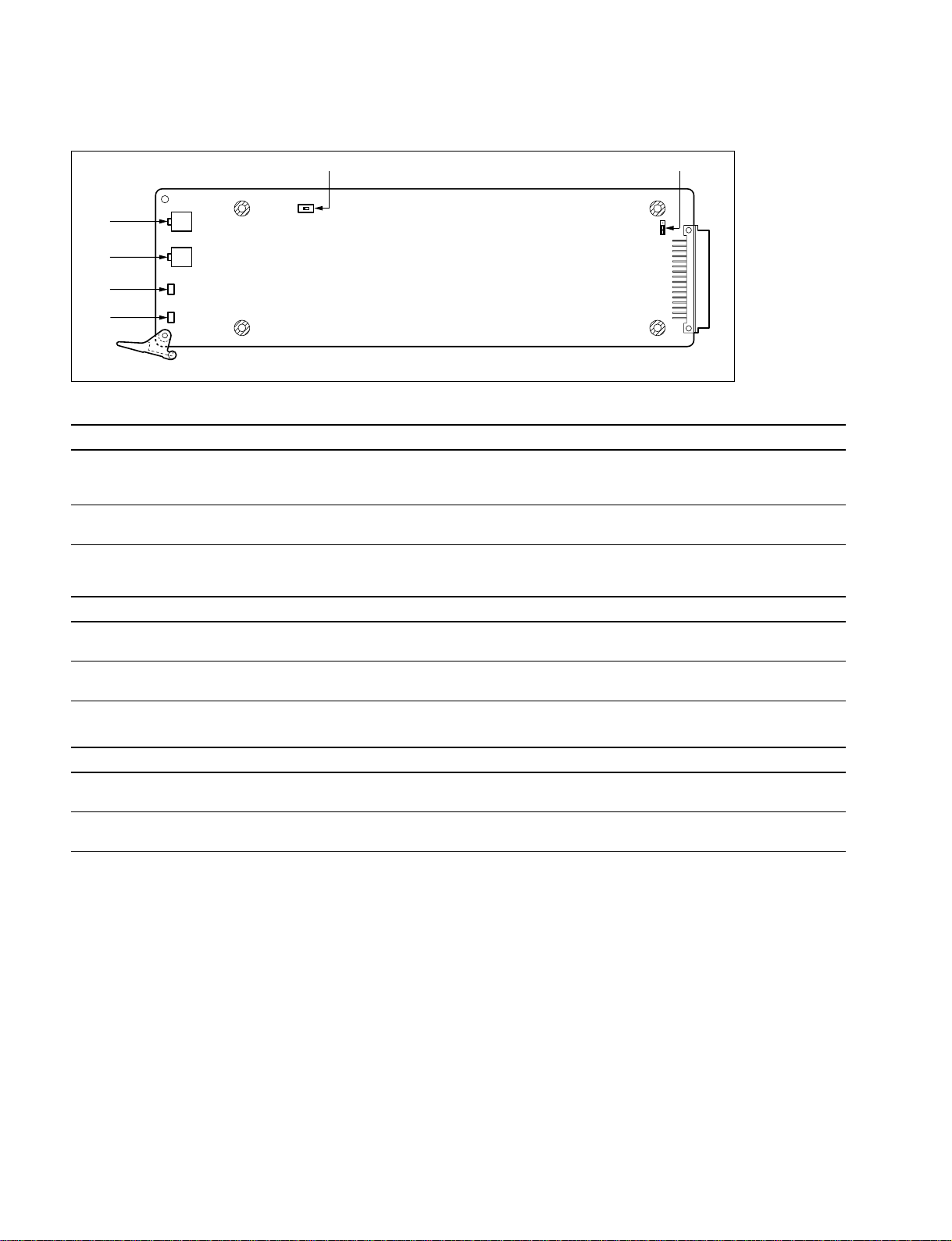
1-4. Name and Function of Switch/Indicator
1-4. Name and Function of Switch/Indicator
1
S101
5
6
3
4
RV102
RV103
D101
D302
Switches/Shorting plug (Factory default settings are indicated by a
No. Ref. No. Name Function
1 S101 CLAMP \ ON: Under normal operation
2 COR101 SINGLE/DIFFERENTIAL \ SINGLE: Under normal operation
OFFON
Main Board (VDA-56 Board: Side A)
OFF: When a signal containing no sync signal is input to the VIDEO IN
connector
DIFFERENTIAL: When a differential signal is input to the VIDEO IN connector
\\
\ mark)
\\
COR101
2
Indicators
No. Ref.No. Name Function
3 D101 VIDEO IN Lights in green: When an analog video signal is input to the VIDEO IN connector
4 D302 _5 V Lights in green: A power supply of _5 V is normal
Lights in red: When a signal is not input to the VIDEO IN connector
Lights in red: A power supply of _5 V is abnormal
Volumes
No. Ref.No. Name Function
5 RV102 EQ Corrects and adjusts the deterioration in the frequency characteristics of the video
signal input to the VIDEO IN connector
6 RV103 GAIN Corrects and adjusts the deterioration in the level of the video signal input to the
VIDEO IN connector
1-2 (E)
BKPF-L703A
Page 9

Section 2
Electrical Alignment
2-1. Electrical Alignment Overview
2-1-1. Required Equipment and Tools
Use the equipment listed below or the equivalent.
Item Model Remarks
Extension board EX-731 (Part No.A-8322-598-A) For the VDA-56 board extension
Analog video signal generator* Tektronix 1410 For 525 mode
Tektronix 1411 For 625 mode
Analog video signal generator* TSG-170A For 525 mode
TSG-271A For 625 mode
Audio signal generator* Tektronix SG505 (option 02 type)
Audio level meter*_
Oscilloscope* Tektronix 2465B
Interface unit Sony PFV-L10/L02
Composite video monitor Sony PVM-1444Q
Waveform/vector monitor* Tektronix 1780R For 525 mode
Tektronix 1781R For 625 mode
Digital voltmeter*_
Adjustment screwdriver*_ Insulation type
Resister (600 Z) _ within 1%
Terminal connector _ BNC type (Feed-through), 75 Z, 3 pcs
*: Use the equipment after calibration has been completed.
BKPF-L703A
2-1 (E)
Page 10
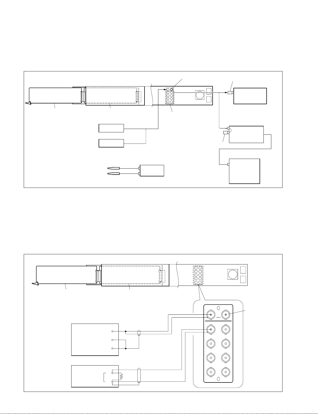
2-1. Electrical Alignment Overview
2-1-2. Connection
n
The interface unit in the connection diagram shown below uses PFV-L10.
VDA-56 board
PFV-L10 (Side)
PFV-L10 (Rear)
Extension board EX-731
Signal generator (TSG-170A/271A)
VIDEO IN
75 Z terminator
VIDEO OUT
BKPF-L703A
75 Z terminator
Waveform/vector monitor
(1780R/1781R)
Signal generator (1410/1411)
75 Z terminator
Composite video monitor
(PVM-1444Q)
Digital voltmeter
+
CH-A
_
m
. To the loop-through output connector, be sure to insert a 75 Z terminator.
. Use a cable of about 1 m in length to connect between a signal generator (TSG-170A/271A) and the
VIDEO IN connector of BKPF-L703A.
. Obtain the output signal of signal generator 1410/1411 from pin 6 of the MODULE OUTPUTS
connector on the connector panel.
Oscilloscope (2465B)
CH1
PIX OUT
When performing the CMR (Common Mode Rejection) adjustment (Section 2-4)
VDA-56 board
Audio signal generator (SG505)
OUTPUT
COM
Audio level meter
INPUT
PFV-L10 (Side)
Extension board EX-731
+
_
+
600 Z
_
PFV-L10 (Rear)
VIDEO IN
1
3
5
7
BKPF-L703A
VIDEO OUT
75 Z terminator
2
4
6
8
L703A
2-2 (E)
BKPF-L703A
Page 11
2-2. Preparation for Adjustment
2-3. +5 V Power Voltage Adjustment
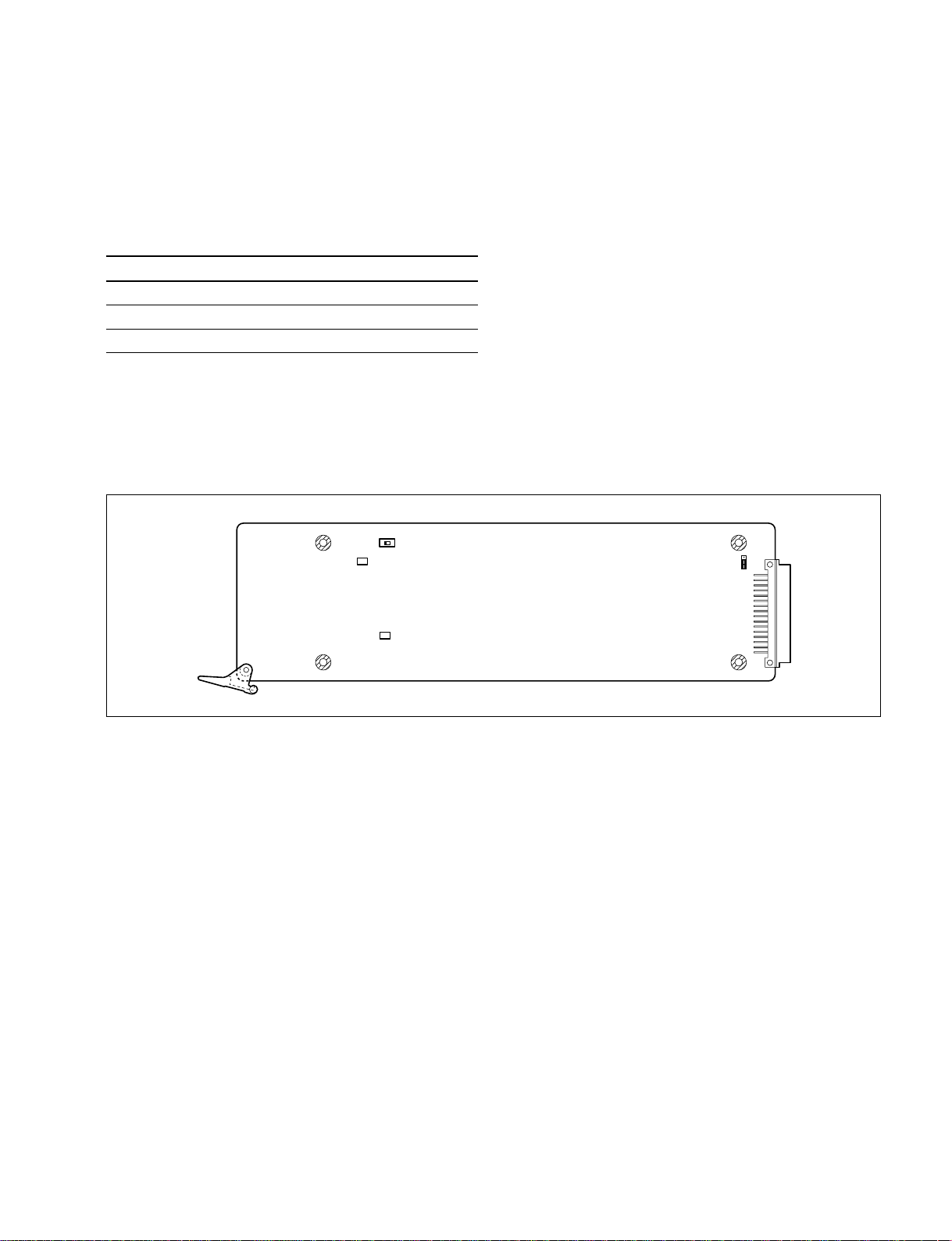
2-2. Preparation for Adjustment
1. Extend the VDA-56 board with the extension board
EX-731.
2. Set the switch and variable resistors (RV) on the
VDA-56 board as shown below.
Ref.No. (Address) Initial setting
S101 (C-1) ON
RV102 (A-1) Counterclockwise 3 fully
RV103 (A-2) Counterclockwise 3 fully
3. Turn on the power of the PFV-L10/L02 and warm up
the unit for about 10 minutes.
S101
1
1
RV102
RV103
E1
OFFON
2-3.
++
+5 V Power Voltage Adjustment
++
n
Be sure to perform the “+5 V Power Voltage Adjustment”
before performing other adjustments.
Measuring equipment: Digital voltmeter
1. Set the digital voltmeter as follows:
Range: AUTO
Mode: DC V
2. Connect the probe of the digital voltmeter as follows:
+: TP301/VDA-56 (C-3)
_: E1/VDA-56 (C-1)
3. Adjust the voltage.
Adjustment point: 1RV301/VDA-56 (C-3)
Specification: 5.00 ±0.05 V dc
COR101
1
1
RV104
RV103
TP301
1
RV301
VDA-56 board (Side A)
BKPF-L703A
2-3 (E)
Page 12

2-4. CMR (Common Mode Rejection) Adjustment
2-5. VIDEO OUT Level Adjustment
2-4. CMR (Common Mode Rejection)
Adjustment
n
Perform “2-3. +5 V Power Voltage Adjustment” in
advance.
Measuring equipment: Audio level meter
1. Turn off switch S101 on the VDA-56 board and set
shorting plug COR101 to DIFFERENTIAL.
2. Connect an audio signal generator and audio level
meter to the connector of BKPF-L703A. (Refer to
Section 2-1-2.)
3. Set the output level of the audio signal generator to
+5 dBm, 60 Hz.
4. Adjust so that specification A is satisfied.
Measurement point: VIDEO OUT 1
(BKPF-L703A connector panel)
Adjustment point: 1RV104/VDA-56 (J-1)
Specification: A < _65 dBm
5. Turn on switch S101 and return shorting plug COR101
to SINGLE.
2-5. VIDEO OUT Level Adjustment
n
Perform “2-3. +5 V Power Voltage Adjustment” in
advance.
Measuring equipment: Waveform/vector monitor
1. Supply 75% color bars signal from the signal generator
(TSG-170A/271A) to the VIDEO IN connector.
2. Connect and set the waveform/vector monitor.
CH-A: VIDEO OUT 1 (BKPF-L703A connector panel)
MODE: WAVEFORM
INPUT: CH-A
REF: INT
3. Adjust 1RV103 (A-2) so that the level A satisfies the
specifications.
Adjustment point: 1RV103/VDA-56 (A-2)
Specification: 140 ±2 IRE
4. Make sure that VIDEO OUT 2 thru 8 connectors
satisfy the specification.
A
2-4 (E)
BKPF-L703A
Page 13

2-6. VIDEO OUT Frequency Response Adjustment
2-7. VIDEO OUT Offset Adjustment
2-6. VIDEO OUT Frequency Response
Adjustment
n
Perform “2-3. +5 V Power Voltage Adjustment” in
advance.
Measuring equipment: Waveform/vector monitor
1. Supply 6 MHz SWEEP signal from the signal
generator (1410/1411) to the VIDEO IN connector.
2. Connect and set the waveform/vector monitor.
CH-A: VIDEO OUT 1 (BKPF-L703A connector panel)
MODE: WAVEFORM
INPUT: CH-A
3. Adjust an amplitude of 1 to 5 MHz with an amplitude
of 500 kHz as the reference (100%).
Adjustment point: 1RV102/VDA-56 (A-1)
Specification: A = 0 ±3.5% (0 ±0.3 dB)
4. Make sure that the output signal in the VIDEO OUT 2
thru 8 connectors satisfy the specifications.
2-7. VIDEO OUT Offset Adjustment
n
Perform “2-3. +5 V Power Voltage Adjustment” in
advance.
Measuring equipment: Oscilloscope
1. Supply 75% color bars signal from the signal generator
(TSG-170A/271A) to the VIDEO IN connector.
2. Connect and set the waveform/vector monitor.
CH1: VIDE O O U T 1 (BKPF-L703A connector panel)
CH1: 10 mV/DIV DC
TIME: 20 us/DIV
TRIG: CH1
3. Adjust 1RV101 (G-1) so that the level A satisfies the
specifications.
Adjustment point: 1RV101/VDA-56 (G-1)
Specification: The pedestal level is 0 ±20 mV DC.
4. Make sure that the output signal in the VIDEO OUT 2
thru 8 connectors satisfy the specifications.
500 k (Reference)
A
1 M 2 M 3 M 4 M 5 M
A
Pedestal level
A
GND
DC 0 V
BKPF-L703A
2-5 (E)
Page 14

2-8. Vector Waveform Check
2-9. DP & DG
*
Check
2-8. Vector Waveform Check
2-9. DP & DG
**
*
**
Check
n
Perform “2-3. +5 V Power Voltage Adjustment” in
advance.
Measuring equipment: Waveform/vector monitor
1. Supply 75% color bars signal from the signal generator
(TSG-170A/271A) to the VIDEO IN connector.
2. Connect and set the waveform/vector monitor.
CH-A: VIDEO OUT 1 (BKPF-L703A connector panel)
MODE: VECTOR
INPUT: CH-A
3. Confirm that each luminance point is located in “4”
when the burst level is adjusted to the reference.
4. Make sure that the output signal in the VIDEO OUT 2
thru 8 connectors satisfy the specifications.
R
M
G
Y
L
B
n
Perform “2-3. +5 V Power Voltage Adjustment” in
advance.
Measuring equipment: Waveform/vector monitor
1. Supply ramp signal (with chroma) from the signal
generator (TSG-170A/271A) to the VIDEO IN
connector.
2. Connect and set the waveform/vector monitor.
CH-A: VIDEO OUT 1 (BKPF-L703A connector panel)
MODE: VECTOR
DP & DG measuring
INPUT: CH-A
m
To change to the DP & DG measuring display, push
the measure button and touch DP & DG item on the
display (the display is a touch panel).
3. Confirm that the specification below is satisfied.
Specification: DP < 0.5d
DG < 0.5%
4. Make sure that the output signal in the VIDEO OUT 2
thru 8 connectors satisfy the specifications.
G
Cr
DP
DG
* DP: Differential Phase
DG: Differential Gain
2-6 (E)
BKPF-L703A
Page 15

------------CN-1982 BOARD
------------ Ref. No.
or Q'ty Part No. SP Description
Section 3
Spare Parts
-----------------------VDA-56 BOARD ;Suffix -12
----------------------- Ref. No.
or Q'ty Part No. SP Description
1pc A-8327-449-A o MOUNTED CIRCUIT BOARD, CN-1982
1pc 1-680-193-11 o PRINTED WIRING BOARD, CN-1983
5pcs 7-621-775-10 s SCREW +B2.6X4
CN1+CN2 1-793-325-11 s CONNECTOR, COAXIAL (BNC TYPE)
CN3+CN4 1-793-325-11 s CONNECTOR, COAXIAL (BNC TYPE)
CN5+CN6 1-793-325-11 s CONNECTOR, COAXIAL (BNC TYPE)
CN7+CN8 1-793-325-11 s CONNECTOR, COAXIAL (BNC TYPE)
CN9+CN10 1-793-325-11 s CONNECTOR, COAXIAL (BNC TYPE)
1pc 1-562-579-11 s RESEPTACLE,CONNECTOR
1pc 3-179-084-01 s LEVER(R),PRINTED C,BOARD
2pcs 7-685-547-14 s SCREW +BTP 3X10(EP-FE/CU,NI,CR
C101 1-164-346-11 s CAPACITOR CHIP CERAMIC 1MF/16V
C102 1-163-239-11 s CAPACITOR,CHIP CERAMIC33PF/50V
C103 1-115-153-11 s CAPACITOR,ELECT 4.7MF/16V(BP)
C104 1-163-038-91 s CAPACITOR,CHIP CERAMIC 0.1MF
C105 1-163-038-91 s CAPACITOR,CHIP CERAMIC 0.1MF
C106 1-164-346-11 s CAPACITOR CHIP CERAMIC 1MF/16V
C107 1-163-243-11 s CAPACITOR CHIP CERAMIC 47PF/50
C108 1-126-391-11 s CAPACITOR ELECT 47MF/6.3V(105)
C109 1-163-038-91 s CAPACITOR,CHIP CERAMIC 0.1MF
C110 1-163-251-11 s CAPACITOR CERAMIC 100PF/50V
C111 1-163-224-11 s CAPACITOR,CHIP CERAMIC 7PF(M-)
C112 1-163-038-91 s CAPACITOR,CHIP CERAMIC 0.1MF
C113 1-163-038-91 s CAPACITOR,CHIP CERAMIC 0.1MF
C114 1-163-243-11 s CAPACITOR CHIP CERAMIC 47PF/50
C115 1-163-239-11 s CAPACITOR,CHIP CERAMIC33PF/50V
C116 1-126-391-11 s CAPACITOR ELECT 47MF/6.3V(105)
C117 1-126-391-11 s CAPACITOR ELECT 47MF/6.3V(105)
C118 1-163-275-11 s CAPACITOR CERAMIC 1000PF/50V
C119 1-163-233-91 s CAPACITOR,CHIP CERAMIC 18PF/50
C120 1-163-239-11 s CAPACITOR,CHIP CERAMIC33PF/50V
C121 1-163-245-11 s CAPACITOR CERAMIC 56PF/50V
C122 1-163-249-11 s CAPACITOR CERAMIC 82PF/50V
C123 1-163-257-11 s CAPACITOR CERAMIC 180PF/50V
C124 1-163-038-91 s CAPACITOR,CHIP CERAMIC 0.1MF
C125 1-163-038-91 s CAPACITOR,CHIP CERAMIC 0.1MF
C126 1-163-038-91 s CAPACITOR,CHIP CERAMIC 0.1MF
C127 1-163-038-91 s CAPACITOR,CHIP CERAMIC 0.1MF
C128 1-126-391-11 s CAPACITOR ELECT 47MF/6.3V(105)
C129 1-126-391-11 s CAPACITOR ELECT 47MF/6.3V(105)
C130 1-163-222-11 s CAPACITOR. CHIP CERAMIC 5.0PF
C131 1-163-220-11 s CAPACITOR, CHIP CERAMIC 3.0PF
C132 1-163-038-91 s CAPACITOR,CHIP CERAMIC 0.1MF
C133 1-126-391-11 s CAPACITOR ELECT 47MF/6.3V(105)
C134 1-163-220-11 s CAPACITOR, CHIP CERAMIC 3.0PF
C135 1-126-391-11 s CAPACITOR ELECT 47MF/6.3V(105)
C136 1-163-038-91 s CAPACITOR,CHIP CERAMIC 0.1MF
C137 1-163-038-91 s CAPACITOR,CHIP CERAMIC 0.1MF
C138 1-163-038-91 s CAPACITOR,CHIP CERAMIC 0.1MF
C139 1-163-038-91 s CAPACITOR,CHIP CERAMIC 0.1MF
C140 1-126-392-11 s CAPACITOR,CHIP ELECT100MF/6.3V
C141 1-126-392-11 s CAPACITOR,CHIP ELECT100MF/6.3V
C142 1-163-038-91 s CAPACITOR,CHIP CERAMIC 0.1MF
C143 1-163-038-91 s CAPACITOR,CHIP CERAMIC 0.1MF
C144 1-126-392-11 s CAPACITOR,CHIP ELECT100MF/6.3V
C145 1-126-392-11 s CAPACITOR,CHIP ELECT100MF/6.3V
C146 1-163-227-11 s CAPACITOR CERAMIC 10PF/50V(CH)
C147 1-163-227-11 s CAPACITOR CERAMIC 10PF/50V(CH)
C148 1-163-227-11 s CAPACITOR CERAMIC 10PF/50V(CH)
C149 1-163-227-11 s CAPACITOR CERAMIC 10PF/50V(CH)
C150 1-163-227-11 s CAPACITOR CERAMIC 10PF/50V(CH)
C151 1-163-227-11 s CAPACITOR CERAMIC 10PF/50V(CH)
C152 1-163-227-11 s CAPACITOR CERAMIC 10PF/50V(CH)
C153 1-163-227-11 s CAPACITOR CERAMIC 10PF/50V(CH)
C154 1-163-038-91 s CAPACITOR,CHIP CERAMIC 0.1MF
C155 1-126-396-11 s CAPACITOR,ELECT 47MF/16V(CHIP)
BKPF-L703A
3-1
Page 16

(VDA-56 BOARD ;Suffix -12)
(VDA-56 BOARD ;Suffix -12)
Ref. No.
or Q'ty Part No. SP Description
C156 1-126-396-11 s CAPACITOR,ELECT 47MF/16V(CHIP)
C157 1-126-396-11 s CAPACITOR,ELECT 47MF/16V(CHIP)
C158 1-126-396-11 s CAPACITOR,ELECT 47MF/16V(CHIP)
C159 1-164-004-11 s CAPACITOR,CERAMIC 0.1MF/25V
C160 1-164-004-11 s CAPACITOR,CERAMIC 0.1MF/25V
C161 1-164-004-11 s CAPACITOR,CERAMIC 0.1MF/25V
C162 1-164-004-11 s CAPACITOR,CERAMIC 0.1MF/25V
C163 1-164-004-11 s CAPACITOR,CERAMIC 0.1MF/25V
C301 1-128-400-11 s CAPACITOR, ELECT 47MF/25V
C302 1-109-892-11 s CAPACITOR ERECT 47MF/25V(105C)
C303 1-163-038-91 s CAPACITOR,CHIP CERAMIC 0.1MF
Ref. No.
or Q'ty Part No. SP Description
L101 1-410-802-11 s CHIP INDUCTOR 0.039UH (3225)
L102 1-410-389-31 s INDUCTOR,CHIP 47UH (3225)
L103 1-410-658-31 s INDUCTOR,CHIP 220UH (3225)
L301 1-424-643-11 s COIL, CHOKE 10UH
L302 1-424-643-11 s COIL, CHOKE 10UH
L303 1-424-643-11 s COIL, CHOKE 10UH
L304 1-410-381-11 s INDUCTOR,CHIP 10UH (3225)
L305 1-410-381-11 s INDUCTOR,CHIP 10UH (3225)
L306 1-410-381-11 s INDUCTOR,CHIP 10UH (3225)
L307 1-410-381-11 s INDUCTOR,CHIP 10UH (3225)
PS301 ! 1-533-282-21 s CIRCUIT PROTECTOR 2A (3225)
C304 1-163-038-91 s CAPACITOR,CHIP CERAMIC 0.1MF
C305 1-126-392-11 s CAPACITOR,CHIP ELECT100MF/6.3V
C306 1-126-392-11 s CAPACITOR,CHIP ELECT100MF/6.3V
C307 1-163-038-91 s CAPACITOR,CHIP CERAMIC 0.1MF
Q101 8-729-120-28 s TRANSISTOR 2SC1623-L5L6
Q102 8-729-928-36 s TRANSISTOR DTA114EE
Q103 8-729-112-48 s TRANSISTOR 2SA1462-T1Y33
Q104 8-729-105-68 s TRANSISTOR 2SC3356-K
C308 1-128-391-11 s CAPACITOR,ELECT 330MF/6.3V
Q105 8-729-120-28 s TRANSISTOR 2SC1623-L5L6
C309 1-163-038-91 s CAPACITOR,CHIP CERAMIC 0.1MF
C310 1-126-396-11 s CAPACITOR,ELECT 47MF/16V(CHIP)
C313 1-163-038-91 s CAPACITOR,CHIP CERAMIC 0.1MF
C314 1-100-118-21 s CAPACITOR,ELECT 82MF 16V (8X7)
Q106 8-729-105-68 s TRANSISTOR 2SC3356-K
Q107 8-729-112-48 s TRANSISTOR 2SA1462-T1Y33
Q108 8-729-105-68 s TRANSISTOR 2SC3356-K
Q109 8-729-112-48 s TRANSISTOR 2SA1462-T1Y33
C315 1-100-118-21 s CAPACITOR,ELECT 82MF 16V (8X7)
Q301 8-729-928-90 s TRANSISTOR DTC114EE
C316 1-100-118-21 s CAPACITOR,ELECT 82MF 16V (8X7)
C317 1-100-118-21 s CAPACITOR,ELECT 82MF 16V (8X7)
C318 1-164-506-11 s CAPACITOR,CERAMIC 4.7MF/16V
Q302 8-729-120-28 s TRANSISTOR 2SC1623-L5L6
Q303 8-729-928-36 s TRANSISTOR DTA114EE
C319 1-164-506-11 s CAPACITOR,CERAMIC 4.7MF/16V
R101 1-208-782-11 s RESISTOR,CHIP 1K 1/10W (2012)
C320 1-164-506-11 s CAPACITOR,CERAMIC 4.7MF/16V
C321 1-164-506-11 s CAPACITOR,CERAMIC 4.7MF/16V
R102 1-208-782-11 s RESISTOR,CHIP 1K 1/10W (2012)
R103 1-208-790-11 s RESISTOR,CHIP 2.2K 1/10W(2012)
R104 1-211-960-11 s RESISTOR,CHIP 22 1/10W (2012)
CN101 1-506-746-11 s PIN,DIN CONNECTOR (DIP) 48P
R105 1-211-960-11 s RESISTOR,CHIP 22 1/10W (2012)
COR101 1-564-948-11 o PIN,CONNECTOR 3P
R106 1-208-822-11 s RESISTOR,CHIP 47K 1/10W (2012)
R107 1-208-782-11 s RESISTOR,CHIP 1K 1/10W (2012)
CT101 1-141-423-61 s TRIMMER CAPACITOR 20PF (CHIP)
CT102 1-141-422-11 s CAPACITOR TRIMER 10PF (CHIP)
R108 1-208-850-11 s RESISTOR,CHIP 680K 1/10W(2012)
R109 1-208-814-11 s RESISTOR,CHIP 22K 1/10W (2012)
R110 1-211-960-11 s RESISTOR,CHIP 22 1/10W (2012)
D101 8-719-027-84 s LED CL-155UR/G-D
D102 8-719-104-34 s DIODE 1S2836
D103 8-719-159-06 s DIODE RD4.7SB-T2
D104 8-719-159-06 s DIODE RD4.7SB-T2
D105 8-719-800-76 s DIODE 1SS226
R111 1-208-782-11 s RESISTOR,CHIP 1K 1/10W (2012)
R112 1-216-639-11 s RESISTOR,CHIP 330 1/10W (2012)
R113 1-208-784-11 s RESISTOR,CHIP 1.2K 1/10W(2012)
R114 1-216-646-11 s RESISTOR,CHIP 620 1/10W (2012)
R115 1-216-675-11 s RESISTOR,CHIP 10K 1/10W(2012)
D301 8-719-036-94 s DIODE RD5.6SB-T1
D302 8-719-027-84 s LED CL-155UR/G-D
D303 8-719-048-98 s DIODE RB160L-40TE25
R116 1-216-295-91 s CONDUCTOR, CHIP (2012)
R117 1-211-960-11 s RESISTOR,CHIP 22 1/10W (2012)
R118 1-216-639-11 s RESISTOR,CHIP 330 1/10W (2012)
DD301 1-475-610-11 s CONVERTER UNIT, DC-DC
R119 1-208-774-11 s RESISTOR,CHIP 470 1/10W (2012)
R120 1-218-760-11 s RESISTOR,CHIP 220K 1/10W(2012)
E1 1-535-877-22 s CHIP,CHECKER (TEST POINT)
E2 1-535-877-22 s CHIP,CHECKER (TEST POINT)
E3 1-535-877-22 s CHIP,CHECKER (TEST POINT)
R121 1-216-603-11 s RESISTOR,CHIP 10 1/10W(2012)
R122 1-208-800-11 s RESISTOR,CHIP 5.6K 1/10W(2012)
R123 1-208-750-11 s RESISTOR,CHIP 47 1/10W (2012)
IC101 8-752-052-82 s IC CXA1432M
IC102 8-759-239-55 s IC TC74HC123AF
R124 1-216-623-11 s RESISTOR,CHIP 68 1/10W(2012)
R125 1-216-649-11 s RESISTOR,CHIP 820 1/10W (2012)
IC105 6-704-406-01 s IC LM1881MX/NOPB
IC106 8-759-271-04 s IC LT1252CS8
IC107 8-759-271-04 s IC LT1252CS8
R126 1-208-793-11 s RESISTOR,CHIP 3K 1/10W (2125)
R127 1-208-801-11 s RESISTOR,CHIP 6.2K 1/10W(2012)
R128 1-208-822-11 s RESISTOR,CHIP 47K 1/10W (2012)
IC108 8-759-271-04 s IC LT1252CS8
IC109 8-759-035-87 s IC SC7S00F
R129 1-208-758-11 s RESISTOR,CHIP 100 1/10W (2012)
R130 1-216-622-11 s RESISTOR,CHIP 62 1/10W (2012)
IC110 8-759-271-04 s IC LT1252CS8
IC111 8-759-271-04 s IC LT1252CS8
IC301 8-759-492-38 s IC LM2941CSX
R131 1-208-782-11 s RESISTOR,CHIP 1K 1/10W (2012)
R132 1-216-633-11 s RESISTOR,CHIP 180 1/10W (2012)
R133 1-216-295-91 s CONDUCTOR, CHIP (2012)
IC303 8-759-579-74 s IC LM2665M6X
IC304 8-749-014-79 s IC LM2664M6X
R134 1-211-960-11 s RESISTOR,CHIP 22 1/10W (2012)
R135 1-216-646-11 s RESISTOR,CHIP 620 1/10W (2012)
3-2
BKPF-L703A
Page 17

(VDA-56 BOARD ;Suffix -12)
(VDA-56 BOARD ;Suffix -12)
Ref. No.
or Q'ty Part No. SP Description
R136 1-216-635-11 s RESISTOR,CHIP 220 1/10W (2012)
R137 1-216-639-11 s RESISTOR,CHIP 330 1/10W (2012)
R138 1-208-814-11 s RESISTOR,CHIP 22K 1/10W (2012)
R139 1-208-782-11 s RESISTOR,CHIP 1K 1/10W (2012)
R140 1-216-641-11 s RESISTOR,CHIP 390 1/10W(2012)
R141 1-216-646-11 s RESISTOR,CHIP 620 1/10W (2012)
Ref. No.
or Q'ty Part No. SP Description
RV101 1-237-039-11 s RESISTOR,ADJ,CERMET 100K
RV102 1-230-746-21 s RESISTOR, ADJ, CERMET 500
RV103 1-230-744-11 s RESISTOR,ADJ,CERMET 100
RV104 1-237-029-11 s RESISTOR,ADJ,CERMET 50
RV301 1-237-031-11 s RESISTOR,ADJ,CERMET 200
S101 1-771-709-31 s SWITCH, SLIDE
R142 1-208-758-11 s RESISTOR,CHIP 100 1/10W (2012)
R143 1-216-295-91 s CONDUCTOR, CHIP (2012)
R144 1-211-960-11 s RESISTOR,CHIP 22 1/10W (2012)
R145 1-208-814-11 s RESISTOR,CHIP 22K 1/10W (2012)
TP101 1-535-877-22 s CHIP,CHECKER (TEST POINT)
TP104 1-535-877-22 s CHIP,CHECKER (TEST POINT)
TP105 1-535-877-22 s CHIP,CHECKER (TEST POINT)
TP301 1-535-877-22 s CHIP,CHECKER (TEST POINT)
R146 1-208-758-11 s RESISTOR,CHIP 100 1/10W (2012)
TP303 1-535-877-22 s CHIP,CHECKER (TEST POINT)
R147 1-208-758-11 s RESISTOR,CHIP 100 1/10W (2012)
R148 1-208-782-11 s RESISTOR,CHIP 1K 1/10W (2012)
R149 1-208-782-11 s RESISTOR,CHIP 1K 1/10W (2012)
R150 1-208-822-11 s RESISTOR,CHIP 47K 1/10W (2012)
R151 1-211-960-11 s RESISTOR,CHIP 22 1/10W (2012)
R152 1-211-960-11 s RESISTOR,CHIP 22 1/10W (2012)
R153 1-216-603-11 s RESISTOR,CHIP 10 1/10W(2012)
R154 1-216-298-00 s RESISTOR,CHIP 2.2 1/10(2012)
R155 1-216-298-00 s RESISTOR,CHIP 2.2 1/10(2012)
R156 1-216-603-11 s RESISTOR,CHIP 10 1/10W(2012)
R157 1-211-960-11 s RESISTOR,CHIP 22 1/10W (2012)
R158 1-211-960-11 s RESISTOR,CHIP 22 1/10W (2012)
R159 1-216-603-11 s RESISTOR,CHIP 10 1/10W(2012)
R160 1-216-603-11 s RESISTOR,CHIP 10 1/10W(2012)
R161 1-208-755-11 s RESISTOR,CHIP 75 1/10W (2012)
R162 1-208-755-11 s RESISTOR,CHIP 75 1/10W (2012)
R163 1-208-755-11 s RESISTOR,CHIP 75 1/10W (2012)
R164 1-208-755-11 s RESISTOR,CHIP 75 1/10W (2012)
R165 1-208-755-11 s RESISTOR,CHIP 75 1/10W (2012)
R166 1-208-755-11 s RESISTOR,CHIP 75 1/10W (2012)
R167 1-208-755-11 s RESISTOR,CHIP 75 1/10W (2012)
R168 1-208-755-11 s RESISTOR,CHIP 75 1/10W (2012)
R169 1-216-298-00 s RESISTOR,CHIP 2.2 1/10(2012)
R170 1-216-298-00 s RESISTOR,CHIP 2.2 1/10(2012)
R171 1-216-308-00 s RESISTOR,CHIP 4.7 1/10W(2012)
R172 1-216-308-00 s RESISTOR,CHIP 4.7 1/10W(2012)
R173 1-216-308-00 s RESISTOR,CHIP 4.7 1/10W(2012)
R174 1-216-308-00 s RESISTOR,CHIP 4.7 1/10W(2012)
R175 1-208-782-11 s RESISTOR,CHIP 1K 1/10W (2012)
R176 1-208-782-11 s RESISTOR,CHIP 1K 1/10W (2012)
R177 1-208-782-11 s RESISTOR,CHIP 1K 1/10W (2012)
R178 1-208-782-11 s RESISTOR,CHIP 1K 1/10W (2012)
R179 1-216-607-11 s RESISTOR,CHIP 15 1/10W(2012)
R180 1-208-830-11 s RESISTOR,CHIP 100K 1/10W(2012)
R181 1-216-675-11 s RESISTOR,CHIP 10K 1/10W(2012)
R182 1-208-782-11 s RESISTOR,CHIP 1K 1/10W (2012)
R183 1-208-782-11 s RESISTOR,CHIP 1K 1/10W (2012)
R184 1-208-782-11 s RESISTOR,CHIP 1K 1/10W (2012)
R185 1-208-818-11 s RESISTOR,CHIP 33K 1/10W (2012)
R301 1-208-782-11 s RESISTOR,CHIP 1K 1/10W (2012)
R302 1-208-790-11 s RESISTOR,CHIP 2.2K 1/10W(2012)
R303 1-208-778-11 s RESISTOR,CHIP 680 1/10W (2012)
R304 1-216-675-11 s RESISTOR,CHIP 10K 1/10W(2012)
R306 1-216-681-11 s RESISTOR,CHIP 18K 1/10W (2012)
R307 1-208-782-11 s RESISTOR,CHIP 1K 1/10W (2012)
R308 1-208-782-11 s RESISTOR,CHIP 1K 1/10W (2012)
R309 1-208-782-11 s RESISTOR,CHIP 1K 1/10W (2012)
R310 1-216-639-11 s RESISTOR,CHIP 330 1/10W (2012)
BKPF-L703A
3-3
Page 18

-----------------------VDA-56 BOARD ;Suffix -11
(VDA-56 BOARD ;Suffix -11)
----------------------- Ref. No.
*a:[Lot No. 0A3-223]
or Q'ty Part No. SP Description
*b:[Lot No. 224-]
C153 1-163-227-11 s CAPACITOR CERAMIC 10PF/50V(CH)
Ref. No.
or Q'ty Part No. SP Description
C154 1-163-038-00 s CAPACITOR, CERAMIC 0.1MF/25V
C155 1-126-396-11 s CAPACITOR,ELECT 47MF/16V(CHIP)
C156 1-126-396-11 s CAPACITOR,ELECT 47MF/16V(CHIP)
1pc 1-562-579-11 s RESEPTACLE,CONNECTOR
C157 1-126-396-11 s CAPACITOR,ELECT 47MF/16V(CHIP)
1pc 3-179-085-01 s LEVER(L),PRINTED C.BOARD
2pcs 7-685-547-14 s SCREW +BTP 3X10
C158 1-126-396-11 s CAPACITOR,ELECT 47MF/16V(CHIP)
C159 1-164-004-11 s CAPACITOR,CERAMIC 0.1MF/25V
C101 1-164-346-11 s CAPACITOR CHIP CERAMIC 1MF/16V
C102 1-163-239-11 s CAPACITOR,CHIP CERAMIC33PF/50V
C103 1-115-153-11 s CAPACITOR,ELECT 4.7MF/16V(BP)
C160 1-164-004-11 s CAPACITOR,CERAMIC 0.1MF/25V
C161 1-164-004-11 s CAPACITOR,CERAMIC 0.1MF/25V
C162 1-164-004-11 s CAPACITOR,CERAMIC 0.1MF/25V
C104 1-163-038-00 s CAPACITOR, CERAMIC 0.1MF/25V
C105 1-163-038-00 s CAPACITOR, CERAMIC 0.1MF/25V
C163 1-164-004-11 s CAPACITOR,CERAMIC 0.1MF/25V
C301 1-128-400-11 s CAPACITOR, ELECT 47MF/25V
C106 1-164-346-11 s CAPACITOR CHIP CERAMIC 1MF/16V
C107 1-163-243-11 s CAPACITOR CHIP CERAMIC 47PF/50
C108 1-126-391-11 s CAPACITOR ELECT 47MF/6.3V(105)
C302 1-109-892-11 s CAPACITOR ERECT 47MF/25V(105C)
C303 1-163-038-00 s CAPACITOR, CERAMIC 0.1MF/25V
C304 1-163-038-00 s CAPACITOR, CERAMIC 0.1MF/25V
C109 1-163-038-00 s CAPACITOR, CERAMIC 0.1MF/25V
C110 1-163-251-11 s CAPACITOR CERAMIC 100PF/50V
C305 1-126-392-11 s CAPACITOR,CHIP ELECT100MF/6.3V
C306 1-126-392-11 s CAPACITOR,CHIP ELECT100MF/6.3V
C111 1-163-224-11 s CAPACITOR,CHIP CERAMIC 7PF(M-)
C112 1-163-038-00 s CAPACITOR, CERAMIC 0.1MF/25V
C113 1-163-038-00 s CAPACITOR, CERAMIC 0.1MF/25V
C307 1-163-038-00 s CAPACITOR, CERAMIC 0.1MF/25V
C308 1-128-391-11 s CAPACITOR,ELECT 330MF/6.3V
C309 1-163-038-00 s CAPACITOR, CERAMIC 0.1MF/25V
C114 1-163-243-11 s CAPACITOR CHIP CERAMIC 47PF/50
C115 1-163-239-11 s CAPACITOR,CHIP CERAMIC33PF/50V
C310 1-126-396-11 s CAPACITOR,ELECT 47MF/16V(CHIP)
C313 1-163-038-00 s CAPACITOR, CERAMIC 0.1MF/25V
C116 1-126-391-11 s CAPACITOR ELECT 47MF/6.3V(105)
C117 1-126-391-11 s CAPACITOR ELECT 47MF/6.3V(105)
C118 1-163-275-11 s CAPACITOR CERAMIC 1000PF/50V
C314 1-127-518-11 s CAPACITOR,ELECT 100MF/16V
C315 1-127-518-11 s CAPACITOR,ELECT 100MF/16V
C316 1-127-518-11 s CAPACITOR,ELECT 100MF/16V
C119 1-163-233-11 s CAPACITOR,CHIP CERAMIC 18PF/50
C120 1-163-239-11 s CAPACITOR,CHIP CERAMIC33PF/50V
C317 1-127-518-11 s CAPACITOR,ELECT 100MF/16V
C318 1-164-506-11 s CAPACITOR,CERAMIC 4.7MF/16V
C121 1-163-245-11 s CAPACITOR CERAMIC 56PF/50V
C122 1-163-249-11 s CAPACITOR CERAMIC 82PF/50V
C123 1-163-257-11 s CAPACITOR CERAMIC 180PF/50V
C319 1-164-506-11 s CAPACITOR,CERAMIC 4.7MF/16V
C320 1-164-506-11 s CAPACITOR,CERAMIC 4.7MF/16V
C321 1-164-506-11 s CAPACITOR,CERAMIC 4.7MF/16V
C124 1-163-038-00 s CAPACITOR, CERAMIC 0.1MF/25V
C125 1-163-038-00 s CAPACITOR, CERAMIC 0.1MF/25V
CN101 1-506-746-11 s PIN,DIN CONNECTOR (DIP) 48P
C126 1-163-038-00 s CAPACITOR, CERAMIC 0.1MF/25V
COR101 1-564-948-11 o PIN,CONNECTOR 3P
C127 1-163-038-00 s CAPACITOR, CERAMIC 0.1MF/25V
C128 1-126-391-11 s CAPACITOR ELECT 47MF/6.3V(105)
C129 1-126-391-11 s CAPACITOR ELECT 47MF/6.3V(105)
CT101 1-141-423-61 s TRIMMER CAPACITOR 20PF (CHIP)
CT102 1-141-422-11 s CAPACITOR TRIMER 10PF (CHIP)
C130 1-163-222-11 s CAPACITOR. CHIP CERAMIC 5.0PF
D101 8-719-027-84 s LED CL-155VR/G-D
C131 1-163-220-11 s CAPACITOR, CHIP CERAMIC 3.0PF
C132 1-163-038-00 s CAPACITOR, CERAMIC 0.1MF/25V
C133 1-126-391-11 s CAPACITOR ELECT 47MF/6.3V(105)
C134 1-163-220-11 s CAPACITOR, CHIP CERAMIC 3.0PF
D102 8-719-104-34 s DIODE 1S2836
D103 8-719-159-06 s DIODE RD4.7SB-T2
D104 8-719-159-06 s DIODE RD4.7SB-T2
D105 8-719-800-76 s DIODE 1SS226
C135 1-126-391-11 s CAPACITOR ELECT 47MF/6.3V(105)
D301 8-719-158-15 s DIODE RD5.6SB
C136 1-163-038-00 s CAPACITOR, CERAMIC 0.1MF/25V
C137 1-163-038-00 s CAPACITOR, CERAMIC 0.1MF/25V
D302 8-719-027-84 s LED CL-155VR/G-D
D303 8-719-048-98 s DIODE RB160L-40TE25
C138 1-163-038-00 s CAPACITOR, CERAMIC 0.1MF/25V
C139 1-163-038-00 s CAPACITOR, CERAMIC 0.1MF/25V
DD301 1-475-610-11 s CONVERTER UNIT, DC-DC
C140 1-126-392-11 s CAPACITOR,CHIP ELECT100MF/6.3V
IC101 8-752-052-82 s IC CXA1432M
C141 1-126-392-11 s CAPACITOR,CHIP ELECT100MF/6.3V
C142 1-163-038-00 s CAPACITOR, CERAMIC 0.1MF/25V
C143 1-163-038-00 s CAPACITOR, CERAMIC 0.1MF/25V
C144 1-126-392-11 s CAPACITOR,CHIP ELECT100MF/6.3V
IC102 8-759-239-55 s IC TC74HC123AF
IC105 8-759-987-27 s IC LM1881M
IC106 8-759-271-04 s IC LT1252CS8
IC107 8-759-271-04 s IC LT1252CS8
C145 1-126-392-11 s CAPACITOR,CHIP ELECT100MF/6.3V
IC108 8-759-271-04 s IC LT1252CS8
C146 1-163-227-11 s CAPACITOR CERAMIC 10PF/50V(CH)
C147 1-163-227-11 s CAPACITOR CERAMIC 10PF/50V(CH)
C148 1-163-227-11 s CAPACITOR CERAMIC 10PF/50V(CH)
C149 1-163-227-11 s CAPACITOR CERAMIC 10PF/50V(CH)
IC109 8-759-035-87 s IC SC7S00F
IC110 8-759-271-04 s IC LT1252CS8
IC111 8-759-271-04 s IC LT1252CS8
IC301 8-759-492-38 s IC LM2941CSX
C150 1-163-227-11 s CAPACITOR CERAMIC 10PF/50V(CH)
IC303 8-759-579-74 s IC LM2665M6X
C151 1-163-227-11 s CAPACITOR CERAMIC 10PF/50V(CH)
IC304 8-749-014-79 s IC LM2664M6X
C152 1-163-227-11 s CAPACITOR CERAMIC 10PF/50V(CH)
3-4
BKPF-L703A
Page 19

(VDA-56 BOARD ;Suffix -11)
(VDA-56 BOARD ;Suffix -11)
Ref. No.
or Q'ty Part No. SP Description
L101 1-410-802-11 s CHIP INDUCTOR 0.039UH (3225)
L102 1-410-389-31 s INDUCTOR,CHIP 47UH (3225)
L103 1-410-658-31 s INDUCTOR,CHIP 220UH (3225)
L301 1-424-643-11 s COIL, CHOKE 10UH
L302 1-424-643-11 s COIL, CHOKE 10UH
L303 1-424-643-11 s COIL, CHOKE 10UH
L304 1-410-381-11 s INDUCTOR,CHIP 10UH (3225)
L305 1-410-381-11 s INDUCTOR,CHIP 10UH (3225)
L306 1-410-381-11 s INDUCTOR,CHIP 10UH (3225)
L307 1-410-381-11 s INDUCTOR,CHIP 10UH (3225)
PS301 ! 1-533-282-21 s CIRCUIT PROTECTOR 2A (3225)
Ref. No.
or Q'ty Part No. SP Description
R136 1-216-635-11 s RESISTOR,CHIP 220 1/10W (2012)
R137 1-216-639-11 s RESISTOR,CHIP 330 1/10W (2012)
R138 1-216-683-11 s RESISTOR,CHIP 22K 1/10W (2012)
R139 1-216-651-11 s RESISTOR,CHIP 1K 1/10W(2012)
R140 1-216-641-11 s RESISTOR,CHIP 390 1/10W(2012)
R141 1-216-646-11 s RESISTOR,CHIP 620 1/10W (2012)
R142 1-216-627-11 s RESISTOR,CHIP 100 1/10W (2012)
R143 1-216-295-00 s CONDUCTOR, CHIP (2012)
R144 1-216-611-11 s RESISTOR,CHIP 22 1/10W (2012)
R145 1-216-683-11 s RESISTOR,CHIP 22K 1/10W (2012)
R146 1-216-627-11 s RESISTOR,CHIP 100 1/10W (2012)
R147 1-216-627-11 s RESISTOR,CHIP 100 1/10W (2012)
Q101 8-729-120-28 s TRANSISTOR 2SC1623-L5L6
Q102 8-729-027-23 s TRANSISTOR DTA114EKA-T146
Q103 8-729-112-65 s TRANSISTOR 2SA1462
R148 1-216-651-11 s RESISTOR,CHIP 1K 1/10W(2012)
R149 1-216-651-11 s RESISTOR,CHIP 1K 1/10W(2012)
R150 1-216-691-11 s RESISTOR,CHIP 47K 1/10W(2012)
Q104 8-729-107-31 s TRANSISTOR 2SC3545
Q105 8-729-120-28 s TRANSISTOR 2SC1623-L5L6
R151 1-216-611-11 s RESISTOR,CHIP 22 1/10W (2012)
R152 1-216-611-11 s RESISTOR,CHIP 22 1/10W (2012)
Q106 8-729-105-68 s TRANSISTOR 2SC3356-K
Q107 8-729-112-65 s TRANSISTOR 2SA1462
Q108 8-729-105-68 s TRANSISTOR 2SC3356-K
R153 1-216-603-11 s RESISTOR,CHIP 10 1/10W(2012)
R154 1-216-298-00 s RESISTOR,CHIP 2.2 1/10(2012)
R155 1-216-298-00 s RESISTOR,CHIP 2.2 1/10(2012)
Q109 8-729-112-65 s TRANSISTOR 2SA1462
Q301 8-729-900-53 s TRANSISTOR DTC114EK
R156 1-216-603-11 s RESISTOR,CHIP 10 1/10W(2012)
R157 1-216-611-11 s RESISTOR,CHIP 22 1/10W (2012)
Q302 8-729-120-28 s TRANSISTOR 2SC1623-L5L6
Q303 8-729-027-23 s TRANSISTOR DTA114EKA-T146
R158 1-216-611-11 s RESISTOR,CHIP 22 1/10W (2012)
R159 1-216-603-11 s RESISTOR,CHIP 10 1/10W(2012)
R160 1-216-603-11 s RESISTOR,CHIP 10 1/10W(2012)
R101 1-216-651-11 s RESISTOR,CHIP 1K 1/10W(2012)
R102 1-216-651-11 s RESISTOR,CHIP 1K 1/10W(2012)
R103 1-216-659-11 s RESISTOR,CHIP 2.2K 1/10W(2012)
R104 1-216-611-11 s RESISTOR,CHIP 22 1/10W (2012)
R105 1-216-611-11 s RESISTOR,CHIP 22 1/10W (2012)
R161 1-216-624-11 s RESISTOR,CHIP 75 1/10W(2012)
R162 1-216-624-11 s RESISTOR,CHIP 75 1/10W(2012)
R163 1-216-624-11 s RESISTOR,CHIP 75 1/10W(2012)
R164 1-216-624-11 s RESISTOR,CHIP 75 1/10W(2012)
R165 1-216-624-11 s RESISTOR,CHIP 75 1/10W(2012)
R106 1-216-691-11 s RESISTOR,CHIP 47K 1/10W(2012)
R107 1-216-651-11 s RESISTOR,CHIP 1K 1/10W(2012)
R108 1-218-772-11 s RESISTOR,CHIP 680K 1/10W(2012)
R109 1-216-683-11 s RESISTOR,CHIP 22K 1/10W (2012)
R110 1-216-611-11 s RESISTOR,CHIP 22 1/10W (2012)
R166 1-216-624-11 s RESISTOR,CHIP 75 1/10W(2012)
R167 1-216-624-11 s RESISTOR,CHIP 75 1/10W(2012)
R168 1-216-624-11 s RESISTOR,CHIP 75 1/10W(2012)
R169 1-216-298-00 s RESISTOR,CHIP 2.2 1/10(2012)
R170 1-216-298-00 s RESISTOR,CHIP 2.2 1/10(2012)
R111 1-216-651-11 s RESISTOR,CHIP 1K 1/10W(2012)
R112 1-216-639-11 s RESISTOR,CHIP 330 1/10W (2012)
R113 1-216-653-11 s RESISTOR,CHIP 1.2K 1/10W(2012)
R114 1-216-646-11 s RESISTOR,CHIP 620 1/10W (2012)
R115 1-216-675-11 s RESISTOR,CHIP 10K 1/10W(2012)
R171 1-216-308-00 s RESISTOR,CHIP 4.7 1/10W(2012)
R172 1-216-308-00 s RESISTOR,CHIP 4.7 1/10W(2012)
R173 1-216-308-00 s RESISTOR,CHIP 4.7 1/10W(2012)
R174 1-216-308-00 s RESISTOR,CHIP 4.7 1/10W(2012)
R175 1-216-651-11 s RESISTOR,CHIP 1K 1/10W(2012)
R116 1-216-295-00 s CONDUCTOR, CHIP (2012)
R117 1-216-611-11 s RESISTOR,CHIP 22 1/10W (2012)
R118 1-216-639-11 s RESISTOR,CHIP 330 1/10W (2012)
R119 1-216-643-11 s RESISTOR,CHIP 470 1/10W (2012)
R120 1-218-760-11 s RESISTOR,CHIP 220K 1/10W(2012)
R176 1-216-651-11 s RESISTOR,CHIP 1K 1/10W(2012)
R177 1-216-651-11 s RESISTOR,CHIP 1K 1/10W(2012)
R178 1-216-651-11 s RESISTOR,CHIP 1K 1/10W(2012)
R179 1-216-607-11 s RESISTOR,CHIP 15 1/10W(2012)
R180 1-216-699-11 s RESISTOR,CHIP 100K 1/10W(2012)
R121 1-216-603-11 s RESISTOR,CHIP 10 1/10W(2012)
R122 1-216-669-11 s RESISTOR,CHIP 5.6K 1/10W(2012)
R123 1-216-619-11 s RESISTOR CHIP 47 1/10W(2012)
R124 1-216-623-11 s RESISTOR,CHIP 68 1/10W(2012)
R125 1-216-649-11 s RESISTOR,CHIP 820 1/10W (2012)
R181 1-216-675-11 s RESISTOR,CHIP 10K 1/10W(2012)
R182 1-216-651-11 s RESISTOR,CHIP 1K 1/10W(2012)
R183 1-216-651-11 s RESISTOR,CHIP 1K 1/10W(2012)
R184 1-216-651-11 s RESISTOR,CHIP 1K 1/10W(2012)
R185 *b 1-215-457-00 s RESISTOR,METAL FILM 33K 1/4W
R126 1-216-662-11 s RESISTOR,CHIP 3K 1/10W (2012)
*a 1-215-421-00 s RESISTOR,METAL FILM 1K 1/4W
R127 1-216-670-11 s RESISTOR,CHIP 6.2K 1/10W(2012)
R128 1-216-691-11 s RESISTOR,CHIP 47K 1/10W(2012)
R129 1-216-627-11 s RESISTOR,CHIP 100 1/10W (2012)
R130 1-216-622-11 s RESISTOR,CHIP 62 1/10W (2012)
R301 1-216-651-11 s RESISTOR,CHIP 1K 1/10W(2012)
R302 1-216-659-11 s RESISTOR,CHIP 2.2K 1/10W(2012)
R303 1-216-647-11 s RESISTOR,CHIP 680 1/10W (2012)
R304 1-216-675-11 s RESISTOR,CHIP 10K 1/10W(2012)
R131 1-216-651-11 s RESISTOR,CHIP 1K 1/10W(2012)
R306 1-216-681-11 s RESISTOR,CHIP 18K 1/10W (2012)
R132 1-216-633-11 s RESISTOR,CHIP 180 1/10W (2012)
R133 1-216-295-00 s CONDUCTOR, CHIP (2012)
R134 1-216-611-11 s RESISTOR,CHIP 22 1/10W (2012)
R135 1-216-646-11 s RESISTOR,CHIP 620 1/10W (2012)
R307 1-216-651-11 s RESISTOR,CHIP 1K 1/10W(2012)
R308 1-216-651-11 s RESISTOR,CHIP 1K 1/10W(2012)
R309 1-216-651-11 s RESISTOR,CHIP 1K 1/10W(2012)
R310 1-216-639-11 s RESISTOR,CHIP 330 1/10W (2012)
BKPF-L703A
3-5
Page 20

(VDA-56 BOARD ;Suffix -11)
Ref. No.
or Q'ty Part No. SP Description
RV101 1-237-039-11 s RESISTOR,ADJ,CERMET 100K
RV102 1-230-746-21 s RESISTOR, ADJ, CERMET 500
RV103 1-230-744-11 s RESISTOR,ADJ,CERMET 100
RV104 1-237-029-11 s RESISTOR,ADJ,CERMET 50
RV301 1-237-031-11 s RESISTOR,ADJ,CERMET 200
S101 1-553-977-00 s SWITCH,SLIDE (2-1-2)
3-6
BKPF-L703A
Page 21

Section 4
Semiconductor Pin Assignments
The following describes the semiconductor types used in
this unit.
For semiconductors marked with page numbers in the
index, refer to the corresponding pages in this section.
However, in some cases incompatible types are also listed,
therefore, when a part is to be replaced, also refer to the
Spare Parts section.
In addition, for semiconductors with ID Nos., refer to the
separate CD-ROM titled “Semiconductor Pin Assignments”
(Sony Part No. 9-968-546-xx) that allows searching for
parts by semiconductor type or ID No.
The semiconductors in the manual or on the CD-ROM are
listed by equivalent types. Thus the external view or the
index mark indication may differ from the actual type.
Pin assignments and block diagrams are based on the IC
manufacturer’s data book.
Index
DIODE Page or ID No.
1S2835-T1 ....................................................................... DC001-02
1S2836............................................................................. DC001-02
1SS123-T1 .......................................................................DC001-01
1SS226 ............................................................................ DC001-01
RB160L-40TE25 .............................................................. DC007-01
RD4.7SB-T1..................................................................... DC008-04
RD4.7SB-T2..................................................................... DC008-04
RD5.6SB ..........................................................................DC008-04
RD5.6SB-T1..................................................................... DC008-04
LED Page or ID No.
CL-155UR/G-D ................................................................ LC009-03
CL-155UR/G-DT .............................................................. LC009-03
TRANSISTOR Page or ID No.
2SA1462 .......................................................................... TC001-01
2SA1462-T1Y33Y34 ........................................................ TC001-01
2SC1623-L5L6 ................................................................. TC001-02
2SC1623-T1-L5L6 ........................................................... TC001-02
2SC3356-K ...................................................................... TC001-02
2SC3356-T1K .................................................................. TC001-02
2SC3545-T1T43T44 ........................................................ TC001-02
2SC3545-T43................................................................... TC001-02
IC Page or ID No.
CXA1432M..................................................................... CXA1432M
CXA1432M-T4 ............................................................... CXA1432M
LM1881M ..........................................................................LM1881N
LM1881MX........................................................................LM1881N
LM1881MX/NOPB ............................................................LM1881N
LM2664M6X................................................................................ 4-2
LM2665M6X................................................................................ 4-2
LM2941CSX................................................................. LM2941CSX
LT1252CS8................................................................... LT1252CS8
LT1252CS8-E2 ............................................................. LT1252CS8
SC7S00F ..........................................................................TC7S00F
TC74HC123AF ..........................................................TC74HC123P
TC74HC123AF(EL).................................................... TC74HC123P
TC7S00F(TE85R) .............................................................TC7S00F
DTA114EE ....................................................................... TC001-04
DTA114EE-TL.................................................................. TC001-04
DTA114EKA-T146 ........................................................... TC001-04
DTC114EE ....................................................................... TC001-03
DTC114EE-TL ................................................................. TC001-03
DTC114EKA-T146 ........................................................... TC001-03
BKPF-L703A
4-1
Page 22

IC
[|IC|]
LM2664M6X (NS)
SWITCHED-CAPACITOR VOLTAGE CONVERTER
—TOP VIEW—
6
1
GND
2
OUT
3
CAP_
INPUTS
: SHUTDOWN CONTROL
SD
V+
: POSITIVE VOLTAGE SUPPLY
OUTPUT
OUT
: NEGATIVE VOLTAGE
OTHERS
CAP+
: CHARGE-PUMP CAPACITOR, POSITIVE TERMINAL
CAP_
: CHARGE-PUMP CAPACITOR, NEGATIVE TERMINAL
56
V+
OSC
– 2
CAP+
5
V+
4
SD
CAP+
3
CAP_
2
OUT
LM2665M6X (NS)
SWITCHED-CAPACITOR VOLTAGE CONVERTER
—TOP VIEW—
6
1
V+
2
GND
3
CAP_
INPUTS
SD
: SHUTDOWN CONTROL
V+
: POSITIVE VOLTAGE SUPPLY
OUTPUT
OUT
: POSITIVE VOLTAGE
OTHERS
CAP+
: CHARGE-PUMP CAPACITOR, POSITIVE TERMINAL
CAP_
: CHARGE-PUMP CAPACITOR, NEGATIVE TERMINAL
16
V+
– 2
OSC
CAP+
5
OUT
4
SD
CAP+
3
CAP_
5
OUT
4-2
BKPF-L703A
Page 23

Section 5
Block Diagram
OverallOverall
VDA-56
VIDEO IN
LOOP THROUGH OUT
CN1
CN2
CN101 IC110,IC111
1C 1C
1A 1A
1B
1B
2B
2B
2C
2C
CN-1982
(1/2)
DIFF
AMP
RV104
1
CMR
COR101
SINGLE
DIFFERENTIAL
S101
IC101
CLAMP
RV101
1
OFFSET
CLAMP
ON-OFF
IC106
PRE
AMP
ELEMENT
EQ
RV102
1
EQ
RV103
1
GAIN
IC107 IC108
EQ
AMP
CLAMP PULSE
IC105
SYNC
SEP
IC102
MONO
MULTI
PRE
DRIVER
Q103
Q104
NORMAL:H
Q106
Q107
D101
VIDEO IN
Q108
Q109
NORMAL:H
IC109,Q105
CN101
CN101
3C
3C
4A 4A
5C 5C
6A 6A
7C 7C
8A9C8A
9C
10A 10A
CN-1982
(2/2)
CN101
14C 14C
DIAG
CN3
CN4
CN5
CN6
CN7
CN8
CN9
CN10
VIDEO
VIDEO
VIDEO
VIDEO
VIDEO
VIDEO
VIDEO
VIDEO
OUT 1
OUT 2
OUT 3
OUT 4
OUT 5
OUT 6
OUT 7
OUT 8
BKPF-L703A
+5.1V
+5.1V
+5.1V
13A
13B
13C
CN101
13A
13B
13C
IC301
+5V
REG.
DD301
-5V
DC-DC CON.
RV301
1
+5V
(+5.0V)
5V
-5V
NG
DETECT
D301,Q301
D302
-5V
NORMAL:H
Overall
5-1 5-1
Page 24

Page 25

Section 6
10B
7B
9A 15C
6A
8B
2C
3C
5C
8A
14C
5B
5A
8C
1A
12C
2A
16C
1C
9B
13C
12A
15B
4B
4C
2B
9C
1B
14A
7A
10A
6C
10C
3B
14B
13B
13A
6B
11B
4A
16A
11A
15A
16B
12B
7C
3A
11C
(16/48)
CN101
(32/48)
CN101
(35/48)
CN101
(34/48)
CN101
CN7
(40/48)
CN101
(26/48)
CN101
(30/48)
CN101
(45/48)
CN101
(3/48)
CN101
(43/48)
CN101
(29/48)
CN101
(21/48)
CN101
(28/48)
CN101
(24/48)
CN101
(17/48)
CN101
GND
(18/48)
CN101
(25/48)
CN101
(46/48)
CN101
(22/48)
CN101
(5/48)
CN101
(20/48)
CN101
CN9
(6/48)
CN101
GND
(42/48)
CN101
(10/48)
CN101
GND
(13/48)
CN101
(12/48)
CN101
(1/48)
CN101
GND
CN3
(11/48)
CN101
(9/48)
CN101
(2/48)
CN101
(33/48)
CN101
(27/48)
CN101
CN1
(44/48)
CN101
(37/48)
CN101
(23/48)
CN101
(31/48)
CN101
CN5
(38/48)
CN101
(14/48)
CN101
(7/48)
CN101
(36/48)
CN101
(15/48)
CN101
(19/48)
CN101
(4/48)
CN101
(48/48)
CN101
(39/48)
CN101
GND
(8/48)
CN101
(41/48)
CN101
(47/48)
CN101
VIDEO_OUT4
GND
NC
NC
6
5
4
1
2
3
NC
GND
GND
NC
VIDEO_IN(+)
NC
GND
VIDE_OUT5
VIDEO_OUT8
GND
GND
GND
GND
NC
VIDEO_OUT6
VIDEO_IN(-)
GND
6
5
4
1
2
3
VIDEO_IN(-)
NC
VIDEO_OUT2
GND
GND
VIDEO_IN(-)
6
5
4
1
2
3
GND
VIDEO_OUT1
VIDEO_IN(-)
GND
VIDEO_OUT7
6
5
4
1
2
3
NC
NC
GND
GND
6
5
4
1
2
3
NCGND
GND
NC
VIDEO_OUT3
GND
NC
NC
NC
GND
NC
NC
CN-1982
Schematic Diagrams
Index
Board Name Function Page
CN-1982 Connector Board 6-1
VDA-56 Analog Video Distribution Board 6-2
BKPF-L703A (SY) : S/N 10001 and Higher
1
2
3
4
BKPF-L703A
A BCDEFGH
5
CN-1982
BOARD NO. 1-680-192-11, 12
LOT NO. 0A3-
6-1 6-1
Page 26

VDA-56 (1/2)
SUFFIX: -12
VDA-56 (1/2)
SUFFIX: -12
1
R161
75
C146
10pF
R162
75
C147
10pF
Q106
2SC3356-T1K
Q103
2SA1462-T1Y33Y34
0
C134
3pF
R145
C133
47uF
6.3V
6
0.1uF
22k
R146
100
R147
100
C136
0.1uF
C137
R148
1k
+5V
R143
2
C103
4.7uF
R106
47k
R107
1k
IC105
C104
0.1uF
C102
33pF
C105
0.1uF
R185
33k
1
3
8
9
10
+5V
2
-5V
(1/3)
16V
+5V
VCC
VDIN
FVIN
SENS
PEDE
CPIN
VEE
1
RV101
100k
3
-5V
R108
680k
1
2
R104
22
C101
1uF
16V
14
EOUT
VOUT
TP12
TP5
11
R105
22
2
7
12
4
C106
1uF
16V
R111
1k
R112
330
R113
1.2k
C112
0.1uF
R114
C113
0.1uF
3
2
620
RV1:OFFSET ADJ
C110
100pF
+5V
R110
C108
22
47uF
C109
6.3V
0.1uF
8
1
VCC2
CSYNC
VIN
3
VSYNC
6
RSET
47pF
14
C
C107
RD
GND
3
4
+5V
CR
Q
Q
B/B
O/E
R109
22k
15
13
4
5
7
+5V
+5V
R116
7
+
4
R117
-5V
L103
220uH
C111
7pF
0
22
R115
C116
47uF
6.3V
C117
47uF
6.3V
C115
33pF
+5V
10k
C114
47pF
IC106
LT1252CS8-E2
TP101
R121
R118
330
R119
470
C118
0.001uF
6
C
RD
11
C119
18pF
C120
33pF
C121
56pF
C122
82pF
C123
180pF
C124
0.1uF
+5V
7
CR
Q
Q
10
R120
220k
5
12
6
9
10
2SC1623-T1-L5L6
+5V
16
VCC
GND
8
TC74HC123AF(EL)
EQ
3
2
RV102
CT101
20pF
R123
47
R124
68
R125
820
R126
3k
R127
6.2k
R128
47k
R122
5.6k
IC102
TC74HC123AF(EL)
Q101
C125
0.1uF
500
1
3
R129
100
RV103
100
1
R130
GAIN
62
R132
180
RV2:EO
RV3:GAIN
(2/3)
+5V
G
R
D101
CL-155UR/G-DT
VIDEO IN
(3/3)IC102
R131
1k
2
21
43
C126
0.1uF
3
2
C127
0.1uF
+5V
+
-
-5V
R134
R137
330
R133
0
CT102
C128
10pF
47uF
6.3V
7
IC107
6
LT1252CS8-E2
R135
4
620
C129
47uF
6.3V
22
Q102
DTA114EE-TL
+9V
R171
CN101
(1/48)
1A
(2/48)
1B
(3/48)
1C
(4/48)
2A
(5/48)
2B
(6/48)
2C
3
GND
GND
VIDEO_IN
N.C.
GND
GND
SINGLE
DIFFERENTIAL
L101
39nH
COR101
1
2
3
GND
D103
RD4.7SB-T1
D104
RD4.7SB-T1
GND
GND
R180
100k
R181
10k
GND
4
4.7
C159
0.1uF
R182
GND
1k
3
2
R172
C161
4.7
0.1uF
-9V
+9V
R173
4.7
C160
0.1uF
GND
R183
1k
3
R179
2
15
R177
1k
C163
0.1uF
R178
1k
R174
4.7
GND
IC111
LT1252CS8-E2
IC110
LT1252CS8-E2
7
GND
+
6
4
C156
47uF
16V
GNDGND
C157
47uF
16V
7
GND
+
6
4
C158
47uF
16V
GND
-9V
C155
47uF
16V
2
GND
R175
1k
1
RV104
50
CMR
3
R176
1k
C162
0.1uF
R101
1k
D105
1SS123-T1
S101
CLAMP OFF ON
5
IC101
CXA1432M-T4
3
R184
1k
2
GND
1
E1
LM1881MX/NOPB
R102
1k
R103
2.2k
L102
47uH
IC102
TC74HC123AF(EL)
C132
0.1uF
IC108
LT1252CS8-E2
R139
1k
R140
390
C130
5pF
R136
220
R138
22k
R141
620
+5V
5
1
VCC 4
B
Y
2
A
GND
3
IC109
TC7S00F(TE85R)
3
7
+
2
4
R142
100
C135
47uF
C131
3pF
6.3V
R144
22
Q104
2SC3356-T1K
C154
0.1uF
+5V
R153
10
R151
22
R154
2.2
R155
2.2
R152
22
R149
1k
R156
10
2SA1462-T1Y33Y34
R150
47k
Q105
2SC1623-T1-L5L6
C140
C138
100uF
0.1uF
6.3V
R157
22
R158
22
C141
100uF
6.3V
C139
0.1uF
-5V
2SA1462-T1Y33Y34
Q107
3
2
D102
1S2835-T1
1
R159
10
C142
0.1uF
Q108
2SC3356-T1K
R169
TP104
2.2
R170
2.2
R160
10
C143
0.1uF
Q109
POWER DOWN L
NORMAL L
NORMAL_H
C144
100uF
6.3V
C145
100uF
6.3V
R163
75
C148
10pF
R164
75
C149
10pF
R165
75
C150
10pF
R166
75
C151
10pF
R167
75
C152
10pF
R168
75
C153
10pF
E2
TP105
DCDC_NG
VIDEO_EXIST
GND
GND
EO_OUT1
EO_OUT2
GND
GND
GND
GND
EO_OUT3
EO_OUT4
GNE
GND
GND
GND
EO_OUT5
EO_OUT6
GND
GND
GND
GND
EO_OUT7
EO_OUT8
GND
GND
DIAG
CN101
(7/48)
3A
(8/48)
3B
(9/48)
3C
(10/48)
4A
(11/48)
4B
(12/48)
4C
(13/48)
5A
(14/48)
5B
(15/48)
5C
(16/48)
6A
(17/48)
6B
(18/48)
6C
(19/48)
7A
(20/48)
7B
(21/48)
7C
(22/48)
8A
(23/48)
8B
(24/48)
8C
(25/48)
9A
(26/48)
9B
(27/48)
9C
(28/48)
10A
(29/48)
10B
(30/48)
10C
2/2
2/2
CN101
(42/48)
14C
VDA-56 (1/2)
BOARD NO. 1-680-191-12
6-2 (b)6-2 (b)
BKPF-L703A
ABCDEFGH
Page 27

VDA-56 (2/2)
SUFFIX: -12
VDA-56 (2/2)
SUFFIX: -12
+5V
1
(37/48)
(38/48)
(39/48)
(31/48)
(32/48)
(33/48)
(45/48)
(47/48)
(41/48)
(40/48)
(46/48)
(48/48)
CN101
13A
13B
13C
11A
11B
11C
15C
16B
14B
14A
16A
16C
5.1V
5.1V
5.1V
GND
GND
GND
GND
GND
LOAD
N.C.
N.C.
N,C.
PS301
2A
C310
47uF
16V
R304
10k
R306
18k
C313
0.1uF
GND
E3
L301
10uH
L303
10uH
GND
C301
47uF
25V
GND
C302
47uF
25V
C303
0.1uF
GND
GND
DD301
1
+VIN
2
-VIN
C304
0.1uF
+VOUT
-VOUT
5
6
4
3
C305
100uF
6.3V
GND
GND
L302
10uH
C306
100uF
6.3V
GND
IC301
LM2941CSX
4
IN
2
SW
GND
3
OUT
ADJ
FIN
6
5
1
GND
GND
C307
0.1uF
R301
1k
-5V
TP303
-5V
R302
2.2k
+5V
R307
1k
R308
1k
D301
RD5.6SB-T1
RV301
200
R303
680
5V
+5V
R309
GND
TP301
C308
330uF
6.3V
GND
1k
DCDC_NG
Q301
DTC114EE-TL
L304
C318
4.7uF
16V
GND
+5V
C309
0.1uF
GND
GND
GND
IC304
LM2664M6X
5
V+
CAP+
4
SD
CAP-
GND
1
RB160L-40TE25
1
C319
4.7uF
16V
V+
4
SD
Q302
2SC1623-T1-L5L6
1/2
GND
C314
82uF
16V
L306
C317
82uF
16V
OUT
D303
GND
2
6
3
OUT
CAP+
CAP-
2
5
6
3
C316
82uF
16V
G
R
D302
CL-155UR/G-DT
43
21
GND
+9V
-5V
C320
4.7uF
16V
C321
4.7uF
16V
GND
C315
82uF
16V
R310
330
-9V
L307L305
Q303
DTA114EE-TL
2
3
BKPF-L703A
1/2
VIDEO_EXIST
IC302
PCF8574AT
NM
NORMAL L
C311
47uF
6.3V
NM
4
5
6
7
9
10
11
12
+5V
16
VDD
P015SDA
P1
SCL
P2
A2
P3
A1
P4
A0
P5
P6
INT
P7
VSS
8
C312
1uF
16V
NM
14
3
2
1
13
NORMAL L
+5V
R305
100k
NM
GND
IC303
LM2665M6X
87
65
43
21
RB301
100k
NM
CN101
SCL
SDA
CARD_ADRS0
CARD_ADRS1
CARD_ADRS2
15A
15B
CN101
12A
12B
12C
(43/48)
(44/48)
(34/48)
(35/48)
(36/48)
GNDGND
VDA-56 (2/2)
BOARD NO. 1-680-191-12
6-3 (b) 6-3 (b)
GND
4
5
A BCDEFGH
Page 28

VDA-56 (1/2)
SUFFIX: -11
1
C103
4.7uF
R106
47k
2
R107
1k
LM1881MX
C104
0.1uF
C102
33pF
C105
0.1uF
*
1
33k
16V
1
VDIN
3
FVIN
8
SENS
9
PEDE
10
CPIN
+5V
1
RV101
100k
3
-5V
IC105
R108
680k
(1/3)
1
2
+5V
R104
22
C101
VCC
VEE
-5V
2
6
1uF
16V
14
EOUT
VOUT
TP12
TP5
11
R105
22
C108
47uF
6.3V
VIN
RSET
C
C112
0.1uF
2
R111
1k
7
12
4
C106
1uF
16V
R112
330
R113
1.2k
3
2
R114
620
C113
0.1uF
RV101:OFFSET ADJ
C110
100pF
+5V
R110
22
C109
0.1uF
8
1
VCC
CSYNC
3
VSYNC
5
B/B
7
O/E
GND
4
+5V
R109
22k
C107
47pF
14
15
13
CR
Q
4
Q
RD
+5V
3
+5V
R116
7
+
4
R117
22
-5V
L103
220uH
C111
7pF
0
C116
47uF
6.3V
C117
47uF
6.3V
C115
33pF
+5V
R115
10k
C114
47pF
IC106
LT1252CS8-E2
6
9
10
2
(1/48)
(2/48)
(3/48)
(4/48)
(5/48)
(6/48)
CN101
1A
1B
1C
2A
2B
2C
GND
GND
VIDEO_IN
N.C.
GND
GND
SINGLE
DIFFERENTIAL
1
2
3
GND
L101
39nH
COR101
R180
100k
C159
0.1uF
R182
C161
0.1uF
3
0.1uF
R183
D103
RD4.7SB-T1
D104
RD4.7SB-T1
GND
GND
R181
10k
0.1uF
GND
R179
C163
4
MARK LOT NO.
*
5
1
CHANGED INFORMATION
R185 1k →33k 224-
+9V
R171
4.7
GND
1k
3
7
+
2
4
R172
4.7
-9V
GNDGND
+9V
R173
4.7
C160
GND
1k
3
7
+
2
15
-
R177
4
1k
C158
47uF
1k
R174
4.7
-9V
IC111
16V
R178
GND
LT1252CS8-E2
IC110
LT1252CS8-E2
C155
47uF
16V
R175
1k
1
RV104
50
2
CMR
3
RV104:CMR
R176
1k
C157
47uF
16V
C162
0.1uF
GND
R101
1k
1SS123-T1
S101
CLAMP
GND
C156
47uF
GND
GND
6
16V
6
D105
CXA1432M-T4
3
2
1
ON
2
1
3
OFF
R102
1k
R103
2.2k
IC101
R184
1k
GND
E1
L102
47uH
R185
IC102
TC74HC123AF(EL)
VDA-56 (1/2)
SUFFIX: -11
TP101
R121
10
CT101
R118
330
R119
470
C118
0.001uF
6
C
RD
11
TC74HC123AF(EL)
20pF
C119
R123
18pF
47
C120
R124
33pF
68
GAIN
C121
R125
56pF
820
C122
R126
82pF
3k
C123
R127
180pF
6.2k
C124
R128
0.1uF
47k
R122
5.6k
+5V
R120
220k
IC102
7
TC74HC123AF(EL)
5
CR
Q
12
Q
Q101
2SC1623-T1-L5L6
+5V
C125
0.1uF
16
VCC
GND
8
(3/3)IC102
EQ
3
2
RV102
C126
500
0.1uF
1
3
R131
1k
RV103
1
100
R130
2
62
R132
180
C127
0.1uF
R129
100
RV102:EQ
RV103:GAIN
(2/3)
+5V
G
21
43
R
D101
CL-155UR/G-DT
VIDEO IN
R136
+5V
R133
3
7
+
2
4
-5V
R134
22
DTA114EKA-T146
R137
330
220
0
CT102
C128
10pF
47uF
6.3V
IC107
6
LT1252CS8-E2
R135
620
C129
47uF
6.3V
Q102
R143
0
C132
0.1uF
IC108
LT1252CS8-E2
R139
1k
3
7
+
R140
390
2
-
C130
5pF
R138
22k
R141
620
+5V
VCC 4
1
B
2
A
GND
IC109
TC7S00F(TE85R)
4
C134
3pF
R142
100
C135
47uF
C131
3pF
6.3V
R144
22
Q104
2SC3545-T1T43T44
C154
0.1uF
5
Y
3
2SC3356-T1K
Q103
2SA1462-T1Y33Y34
R151
22
R152
22
R149
1k
R153
R154
2.2
R155
2.2
R156
10
47uF
6.3V
6
C133
R146
100
R147
100
C136
0.1uF
R148
1k
2SA1462-T1Y33Y34
+5V
C137
0.1uF
R145
22k
R150
47k
2SC1623-T1-L5L6
Q106
+5V
10
-5V
Q107
3
1
Q105
R159
10
C142
C140
C138
0.1uF
R157
R158
0.1uF
2
D102
1S2835-T1
0.1uF
100uF
6.3V
Q108
2SC3356-T1K
22
R169
2.2
R170
2.2
22
R160
10
C141
C143
100uF
0.1uF
6.3V
C139
Q109
2SA1462-T1Y33Y34
POWER DOWN L
NORMAL L
NORMAL_H
R162
R163
C144
100uF
R164
6.3V
TP104
C145
100uF
6.3V
TP105
75
75
75
R165
75
R166
75
R167
75
75
E2
R161
75
C146
10pF
C147
10pF
C148
10pF
C149
10pF
C150
10pF
C151
10pF
C152
10pF
R168
C153
10pF
GND
GND
EO_OUT1
EO_OUT2
GND
GND
GND
GND
EO_OUT3
EO_OUT4
GNE
GND
GND
GND
EO_OUT5
EO_OUT6
GND
GND
GND
GND
EO_OUT7
EO_OUT8
GND
GND
DCDC_NG
VIDEO_EXIST
DIAG
VDA-56 (1/2)
BOARD NO. 1-680-191-11
2/2
2/2
CN101
3A
3B
3C
4A
4B
4C
5A
5B
5C
6A
6B
6C
7A
7B
7C
8A
8B
8C
9A
9B
9C
10A
10B
10C
CN101
14C
(7/48)
(8/48)
(9/48)
(10/48)
(11/48)
(12/48)
(13/48)
(14/48)
(15/48)
(16/48)
(17/48)
(18/48)
(19/48)
(20/48)
(21/48)
(22/48)
(23/48)
(24/48)
(25/48)
(26/48)
(27/48)
(28/48)
(29/48)
(30/48)
(42/48)
6-2 (a)6-2 (a)
BKPF-L703A
ABCDEFGH
Page 29

VDA-56 (2/2)
SUFFIX: -11
VDA-56 (2/2)
SUFFIX: -11
(37/48)
(38/48)
(39/48)
(31/48)
(32/48)
(33/48)
(45/48)
(47/48)
(41/48)
(40/48)
(46/48)
(48/48)
CN101
13A
13B
13C
11A
11B
11C
15C
16B
14B
14A
16A
16C
5.1V
5.1V
5.1V
GND
GND
GND
GND
GND
LOAD
N.C.
N.C.
N,C.
PS301
2A
C310
47uF
16V
R304
10k
R306
18k
C313
0.1uF
GND
E3
L301
10uH
L303
10uH
GND
GND
C301
47uF
25V
C302
47uF
25V
C303
0.1uF
GND
GND
DD301
1
+VIN
2
-VIN
C304
0.1uF
+VOUT
-VOUT
5
6
4
3
C305
100uF
6.3V
GND
GND
L302
10uH
C306
100uF
6.3V
GND
IC301
LM2941CSX
4
2
IN
SW
GND1
OUT
ADJ
GND2
3
6
5
1
GND
GND
C307
0.1uF
R301
1k
-5V
TP303
-5V
R302
2.2k
+5V
R307
1k
R308
1k
D301
RD5.6SB-T1
RV301
200
R303
680
+5V
R309
1k
Q301
DTC114EKA-T146
GND
L304
RV301:+5V ADJ
TP301
5V
330uF
6.3V
GND
GND
+5V
C308
GND
C318
4.7uF
16V
C309
0.1uF
DCDC_NG
GND
GND
IC304
LM2664M6X
5
V+
CAP+
4
SD
CAP-
GND
1
RB160L-40TE25
1
C319
4.7uF
16V
V+
4
SD
Q302
2SC1623-T1-L5L6
1/2
OUT
D303
GND
2
6
3
OUT
CAP+
CAP-
2
C316
100uF
16V
5
6
3
L306
C317
100uF
16V
GND
C314
100uF
16V
+5V
G
R
D302
CL-155UR/G-DT
43
21
GND
+9V
-5V
C320
4.7uF
16V
C321
4.7uF
16V
R310
GND
L307L305
C315
100uF
16V
330
-9V
1
Q303
DTA114EKA-T146
2
3
BKPF-L703A
1/2
VIDEO_EXIST
IC302
PCF8574AT
NM
NORMAL L
C311
47uF
6.3V
NM
4
5
6
7
9
10
11
12
+5V
16
VDD
P015SDA
P1
SCL
P2
P3
A2
P4
A1
P5
A0
P6
P7
INT
VSS
8
C312
1uF
16V
NM
14
3
2
1
13
NORMAL L
+5V
R305
100k
NM
GND
IC303
LM2665M6X
87
65
43
21
RB301
100k
NM
CN101
SCL
SDA
CARD_ADRS0
CARD_ADRS1
CARD_ADRS2
15A
15B
CN101
12A
12B
12C
(43/48)
(44/48)
(34/48)
(35/48)
(36/48)
GNDGND
VDA-56 (2/2)
BOARD NO. 1-680-191-11
6-3 (a) 6-3 (a)
GND
4
5
A BCDEFGH
Page 30

Page 31

Section 7
Board Layout
VDA-56
SUFFIX: -12
VDA-56
SUFFIX: -12
VDA-56
-A SIDE-
SUFFIX: -12
VDA-56 -B SIDE-
SUFFIX: -12
—————————————————————
VDA-56 (1-680-191-12)
—————————————————————
C101 G1
C102 E1
C103 F1
C104 D1
C105 D1
C106 F1
C107 D1
C108 E1
C109 D1
C110 F1
C111 F1
C112 E1
C113 E1
C114 D1
C115 F1
C116 F1
C117 E1
C118 D1
C119 B1
C120 B1
C121 B1
C122 B1
C123 B1
C124 B1
C125 D1
C126 B2
C127 B2
C128 B2
C129 A2
C130 G2
C131 G2
C132 G2
C133 G2
C134 G2
C135 G2
C136 G2
C137 C1
C138 H2
C139 H2
C140 H1
C141 H3
C142 H2
C143 H2
C144 H1
C145 H3
C146 J2
C147 J2
C148 J2
C149 J2
C150 J2
C151 J2
C152 J2
C153 J2
C154 D1
C155 H1
C156 G1
C157 G1
C158 G1
C159 H1
C160 H1
C161 H1
C162 H1
C163 J1
C301 H3
C302 D3
C303 H3
C304 D3
C305 F3
C306 F3
C307 F3
C308 D3
C309 E3
C310 H3
C311 F2
C312 E2
C313 H3
C314 C3
C315 B3
C316 E3
C317 E3
C318 E3
C319 C3
C320 E2
C321 B3
CN101 J2
COR101 J1
CT101 A1
CT102 G2
D101 A2
D102 D1
D103 J1
D104 J1
D105 G1
D301 F3
D302 A3
D303 C3
DD301 G3
E1 C1
E2 H2
E3 G1
IC101 F1
IC102 D1
IC105 D1
IC106 E1
IC107 B2
IC108 G2
IC109 D1
IC110 H1
IC111 H1
IC301 C3
IC302 E2
IC303 C3
IC304 E3
L101 J1
L102 E1
L103 F1
L301 H3
L302 F3
L303 D3
L304 E3
L305 C3
L306 E2
L307 B3
PS301 J3
Q101 A2
Q102 A2
Q103 H2
Q104 H2
Q105 C1
Q106 H2
Q107 H2
Q108 H2
Q109 H2
Q301 F3
Q302 A3
Q303 A3
R101 H1
R102 E1
R103 E1
R104 F1
R105 F1
R106 F1
R107 F1
R108 D1
R109 D1
R110 E1
R111 E1
R112 F1
R113 F1
R114 F1
R115 D1
R116 F1
R117 E1
R118 E1
R119 F1
R120 D1
R121 E1
R122 B1
R123 B1
R124 B1
R125 B1
R126 B1
R127 B1
R128 B1
R129 A1
R130 A1
R131 A1
R132 B2
R133 B2
R134 B2
R135 B2
R136 G2
R137 A2
R138 G2
R139 G2
R140 G2
R141 G2
R142 G2
R143 G2
R144 G2
R145 C1
R146 H2
R147 H2
R148 H2
R149 H2
R150 C1
R151 H2
R152 H2
R153 H2
R154 H2
R155 H2
R156 H2
R157 H2
R158 H2
R159 H2
R160 H2
R161 J2
R162 J2
R163 J2
R164 J2
R165 J2
R166 J2
R167 J2
R168 J2
R169 H2
R170 H2
R171 H1
R172 G1
R173 G1
R174 G1
R175 H1
R176 J1
R177 H1
R178 H1
R179 J1
R180 J1
R181 J1
R182 H1
R183 H1
R184 G1
R185 D1
R301 C3
R302 C3
R303 C3
R304 J3
R305 E2
R306 J3
R307 F3
R308 F3
R309 F3
R310 A3
RB301 F2
RV101 G1
RV102 A1
RV103 A2
RV104 J1
RV301 C3
S101 C1
TP101 E1
TP104 H3
TP105 D1
TP301 C3
TP303 F3
BKPF-L703A
7-1
7-1
Page 32

D101
D302
R129
RV102RV103
R130
R137
R310
R131
Q101 Q102
Q302 Q303
CT101
C129
C119
R123
C127
C120
R124
R134
IC107
C121
R125
R133
C122
R126
C126
C123
R127
R135
C124
R128
R132
C128
R122
C315
C321
L307
D303
C319
IC303
L305
C314
C103
R106
C106
C305
VDA-56
SUFFIX: -11
R184
D105
R104
R105
C101
E3
CT102
RV101
R138
C131
R136
R140
C130
R142
R141
R139
R144
C136
C156
DD301
C133
C135
C158
IC108
C132
R143
C134
C157
R171R172 R173R174
R146R147
Q103Q104
C141
C301
C155
C140
R148R149
C138
R153
R151R152
R156
C139
C303
L301
R180
R182R183
C161C162
R176
IC110IC111
Q106Q107
C145
C313
C142
R159
R157R158
R160
C143
R177 R178
Q108Q109
R101
C310
C159C160
R175
C144
R154R155
R169R170
E2
TP104
PS301
RV104
R161
R162
R163
R164
R165
R166
R167
R168
R306
VDA-56 -A SIDE-
SUFFIX: -11
VDA-56 -B SIDE-
SUFFIX: -11
R181
D104
C146
C147
C148
C149
C150
C151
C152
C153
R304
C163
R179
D103
COR101
L101
CN101
—————————————————————
VDA-56 (1-680-191-11)
—————————————————————
C101 G1
C102 E1
C103 F1
C104 D1
C105 D1
C106 F1
C107 D1
C108 E1
C109 D1
C110 F1
C111 F1
C112 E1
C113 E1
C114 D1
C115 F1
C116 F1
C117 E1
C118 D1
C119 B1
C120 B1
C121 B1
C122 B1
C123 B1
C124 B1
C125 D1
C126 B2
C127 B2
C128 B2
C129 A2
C130 G2
C131 G2
C132 G2
C133 G2
C134 G2
C135 G2
C136 G2
C137 C1
C138 H2
C139 H2
C140 H1
C141 H3
C142 H2
C143 H2
C144 H1
C145 H3
C146 J2
C147 J2
C148 J2
C149 J2
C150 J2
C151 J2
C152 J2
C153 J2
C154 D1
C155 H1
C156 G1
C157 G1
C158 G1
C159 H1
C160 H1
C161 H1
C162 H1
C163 J1
C301 H3
C302 D3
C303 H3
C304 D3
C305 F3
C306 F3
C307 F3
C308 D3
C309 E3
C310 H3
C311 F2
C312 E2
C313 H3
C314 C3
C315 B3
C316 E3
C317 E3
C318 E3
C319 C3
C320 E2
C321 B3
CN101 J2
COR101 J1
CT101 A1
CT102 G2
D101 A2
D102 D1
D103 J1
D104 J1
D105 G1
D301 F3
D302 A3
D303 C3
DD301 G3
E1 C1
E2 H2
E3 G1
IC101 F1
IC102 D1
IC105 D1
IC106 E1
IC107 B2
IC108 G2
IC109 D1
IC110 H1
IC111 H1
IC301 C3
IC302 E2
IC303 C3
IC304 E3
L101 J1
L102 E1
L103 F1
L301 H3
L302 F3
L303 D3
L304 E3
L305 C3
L306 E2
L307 B3
PS301 J3
Q101 A2
Q102 A2
Q103 H2
Q104 H2
Q105 C1
Q106 H2
Q107 H2
Q108 H2
Q109 H2
Q301 F3
Q302 A3
Q303 A3
R101 H1
R102 E1
R103 E1
R104 F1
R105 F1
R106 F1
R107 F1
R108 D1
R109 D1
R110 E1
R111 E1
R112 F1
R113 F1
R114 F1
R115 D1
R116 F1
R117 E1
R118 E1
R119 F1
R120 D1
R121 E1
R122 B1
R123 B1
R124 B1
R125 B1
R126 B1
R127 B1
R128 B1
R129 A1
R130 A1
R131 A1
R132 B2
R133 B2
R134 B2
R135 B2
R136 G2
R137 A2
R138 G2
R139 G2
R140 G2
R141 G2
R142 G2
R143 G2
R144 G2
R145 C1
R146 H2
R147 H2
R148 H2
R149 H2
R150 C1
R151 H2
R152 H2
R153 H2
R154 H2
R155 H2
R156 H2
R157 H2
R158 H2
R159 H2
R160 H2
R161 J2
R162 J2
R163 J2
R164 J2
R165 J2
R166 J2
R167 J2
R168 J2
R169 H2
R170 H2
R171 H1
R172 G1
R173 G1
R174 G1
R175 H1
R176 J1
R177 H1
R178 H1
R179 J1
R180 J1
R181 J1
R182 H1
R183 H1
R184 G1
R301 C3
R302 C3
R303 C3
R304 J3
R305 E2
R306 J3
R307 F3
R308 F3
R309 F3
R310 A3
RB301 F2
RV101 G1
RV102 A1
RV103 A2
RV104 J1
RV301 C3
S101 C1
TP101 E1
TP104 H3
TP105 D1
TP301 C3
TP303 F3
VDA-56
SUFFIX: -11
C125
C302
C114
L303
R115
IC105
C105
C104
R108
C109
C308
R110
C320
C108
L306
C309
L102
L304
C317
R120
S101
E1
TP301
RV301
Q105
R302R303
C137
R301
IC109
R145
R150
IC301
C154
D102
C118
TP105
IC102
C304
C107
R109
C117
C102
IC302
C318
C113
R117
R103
R102
IC304
IC106
R118
R111
R121
TP101
R305
C112
C312
C316
R112
R114
R116
C311
R113
R119
C116
D301
R308
R307
R309
Q301
C115
RB301
TP303
C307
L103
C111
C306
C110
L302
IC101
R107
7-2
7-2
BKPF-L703A
Page 33

Page 34

BKPF-L703A (SY) J, E
9-967-931-02
Printed in Japan
Sony Corporation 2003. 11 22
B&P Company ©2000
 Loading...