

Page 1
SDTI-CP OUTPUT BOARD
BKNW-124
! WARNING
This manual is intended for qualified service personnel only.
To reduce the risk of electric shock, fire or injury, do not perform any servicing other than that
contained in the operating instructions unless you are qualified to do so. Refer all servicing to
qualified service personnel.
! WARNUNG
Die Anleitung ist nur für qualifiziertes Fachpersonal bestimmt.
Alle Wartungsarbeiten dürfen nur von qualifiziertem Fachpersonal ausgeführt werden. Um die
Gefahr eines elektrischen Schlages, Feuergefahr und Verletzungen zu vermeiden, sind bei
Wartungsarbeiten strikt die Angaben in der Anleitung zu befolgen. Andere als die angegeben
Wartungsarbeiten dürfen nur von Personen ausgeführt werden, die eine spezielle Befähigung
dazu besitzen.
! AVERTISSEMENT
Ce manual est destiné uniquement aux personnes compétentes en charge de l’entretien. Afin
de réduire les risques de décharge électrique, d’incendie ou de blessure n’effectuer que les
réparations indiquées dans le mode d’emploi à moins d’être qualifié pour en effectuer d’autres.
Pour toute réparation faire appel à une personne compétente uniquement.
INSTALLATION MANUAL
1st Edition (Revised 2)
Page 2

Page 3
BKNW-124
1 (J)
Page 4
2 (J)
BKNW-124
Page 5
BKNW-124
3 (J)
Page 6
4 (J)
BKNW-124
Page 7

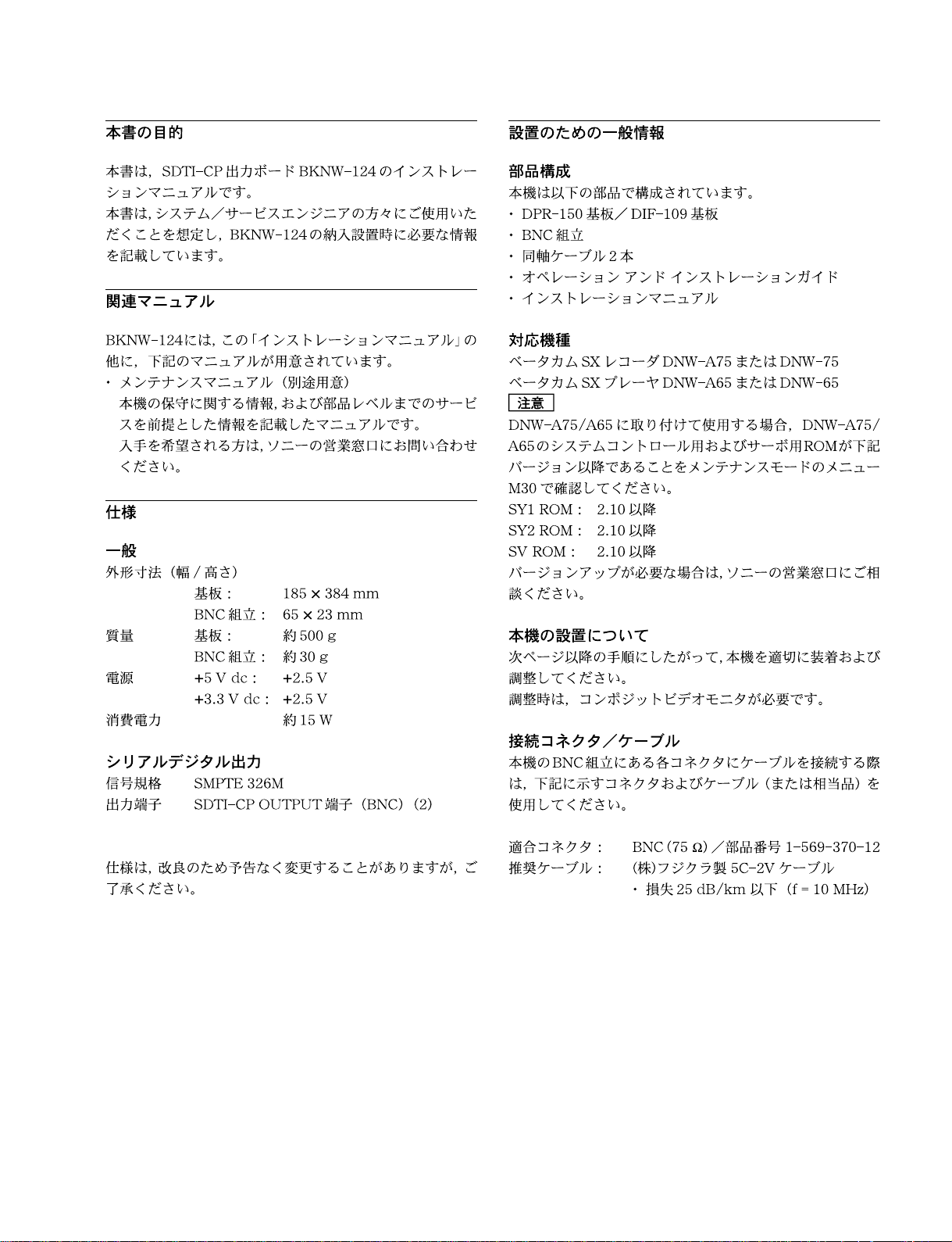
Purpose of this manual
Installation overview
This manual is an installation manual of SDTI-CP Output
Board BKNW-124.
This manual is intended for system and service engineers,
so describes information regarding installation.
Related manual
Besides this installation manual, the following manuals are
available for BKNW-124.
. Maintenance Manual (available on request)
This manual describes the information that premise the
parts level service (adjustment, parts list, diagrams, etc.).
If this manual is required, please contact your local Sony
Sales Office/Service Center.
Specifications
General
Dimensions (w/h) Main board: 185 x 384 mm
BNC assembly: 65 x 23 mm
Mass Main board: approx. 500 g
BNC assembly: approx. 30 g
Power requirements +5 V dc: +2.5 V
+3.3 V dc: +2.5 V
Power consumption approx. 15 W
Serial digital outputs
Signal format Conforms to SMPTE 326M
Output connectors SDTI-CP OUT connectors (BNC
type) (2)
Design and specifications are subject to change without
notice.
Components
BKNW-124 is composed of the following items.
. DPR-150 board/DIF-109 board
. BNC assembly
. Coaxial cables (0.8 m) (2)
. Operation and installation guide
. Installation manual
Applicable models
Betacam SX recorder: DNW-A75/A75P/75/75P
Betacam SX player: DNW-A65/A65P/65/65P
n
In DNW-A75/A75P/A65/A65P:
Before installing BKNW-124 to DNW, check each ROM
version (SY1, SY2, and SV) of DNW by M30 : ROM
VERSION of the maintenance mode.
. SY1 ROM: 2.10 or higher
. SY2 ROM: 2.10 or higher
. SV ROM: 2.10 or higher
If the ROM version is lower than above value, the versionup must be required. For the version-up, contact your local
Sony Sales Office / Service Center.
Installation of BKNW-124
In accordance with next page and later, be sure to attach/
adjust BKNW-124 to DNW.
To perform the adjustment, prepare the analog composite
video monitor.
Matching connector/cable
When external cables are connected to the exterior connectors of the BNC assembly, the hardware listed below (or
equivalents) must be used.
Matching connector : BNC 75 Z / 1-569-370-12
Recommendable cable :BELDEN8281 75 Z coaxial cable
.Deterioration: less than 25 dB/km
(f = 10 MHz)
BKNW-124
1 (E)
Page 8
BKNW-124 installation
n
. Install the BKNW-124 after turning off the power.
. Ensure that the screws secure the four hexagonal
supports on the DIF-109 board are tight. When they are
loose, tighten them. If lost supports and screws, use the
following replacement parts.
Hexagonal support (M3) :Part No. 2-280-622-01
Screws (B 3 x 3) : Part No. 7-682-544-04
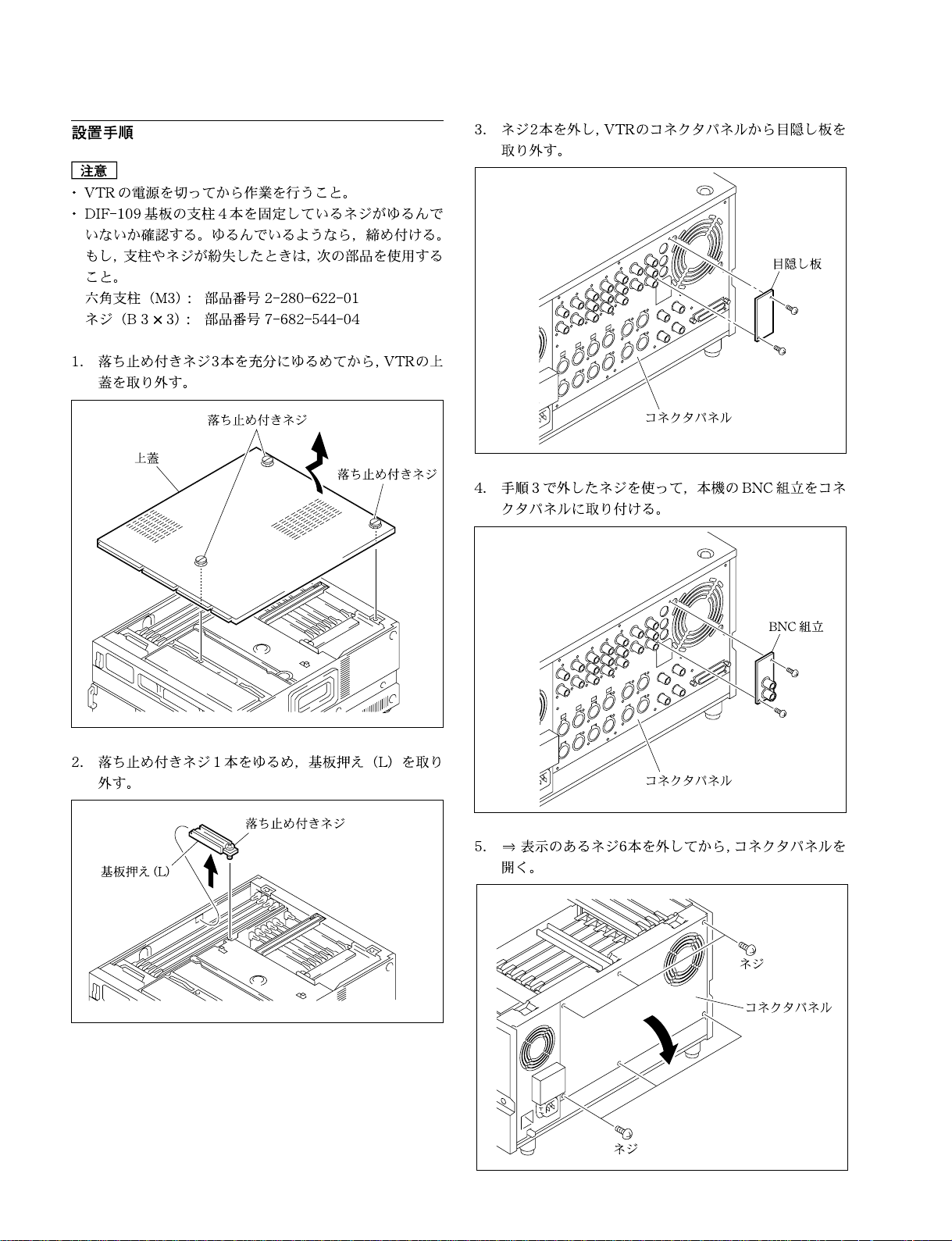
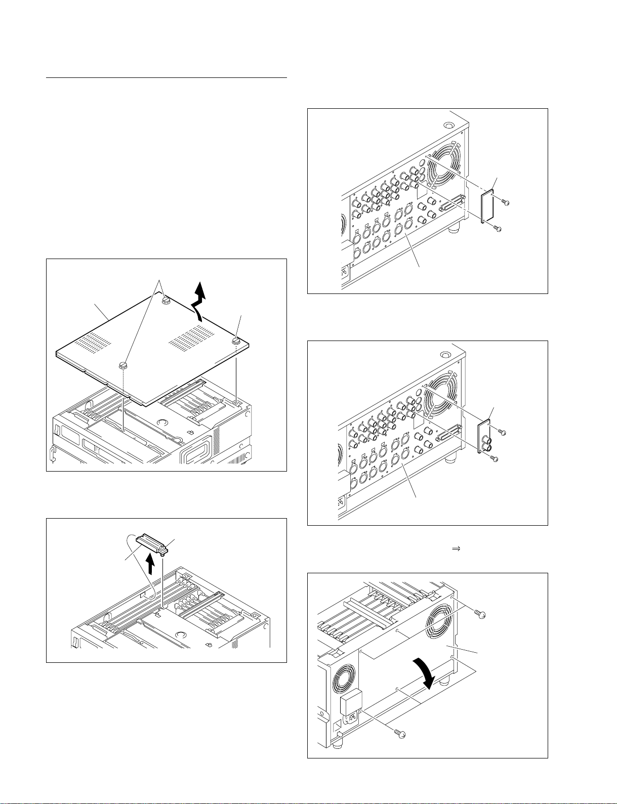
1. With the three screws (with stopper) loosened,
remove the upper lid of DNW.
3. Remove the two screws, then the stop plate will be
removed from the connector panel.
Stop plate
Screws (with stopper)
Upper lid
Screw (with stopper)
2. With the screw (with stopper) loosened, remove the
board retainer (L) of DNW.
Screw (with stopper)
Board retainer (L)
Connector panel
4. Attach the BNC assembly to the connector panel with
the two removed screws in step 3.
BNC assembly
Connector panel
5. With the six screws (indicated on the connector
panel) removed, open the panel.
2 (E)
Screws
Connector panel
Screws
BKNW-124
Page 9
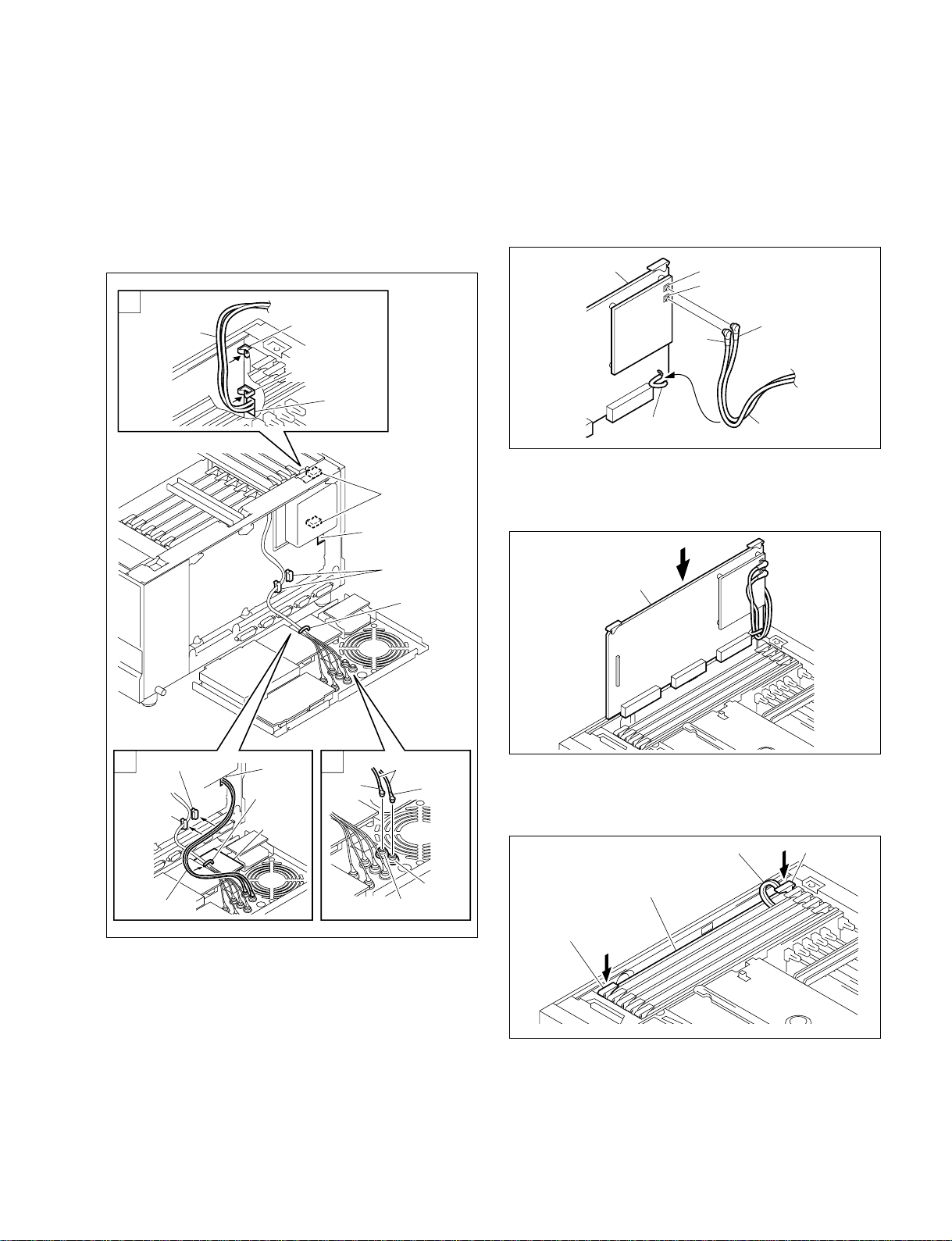
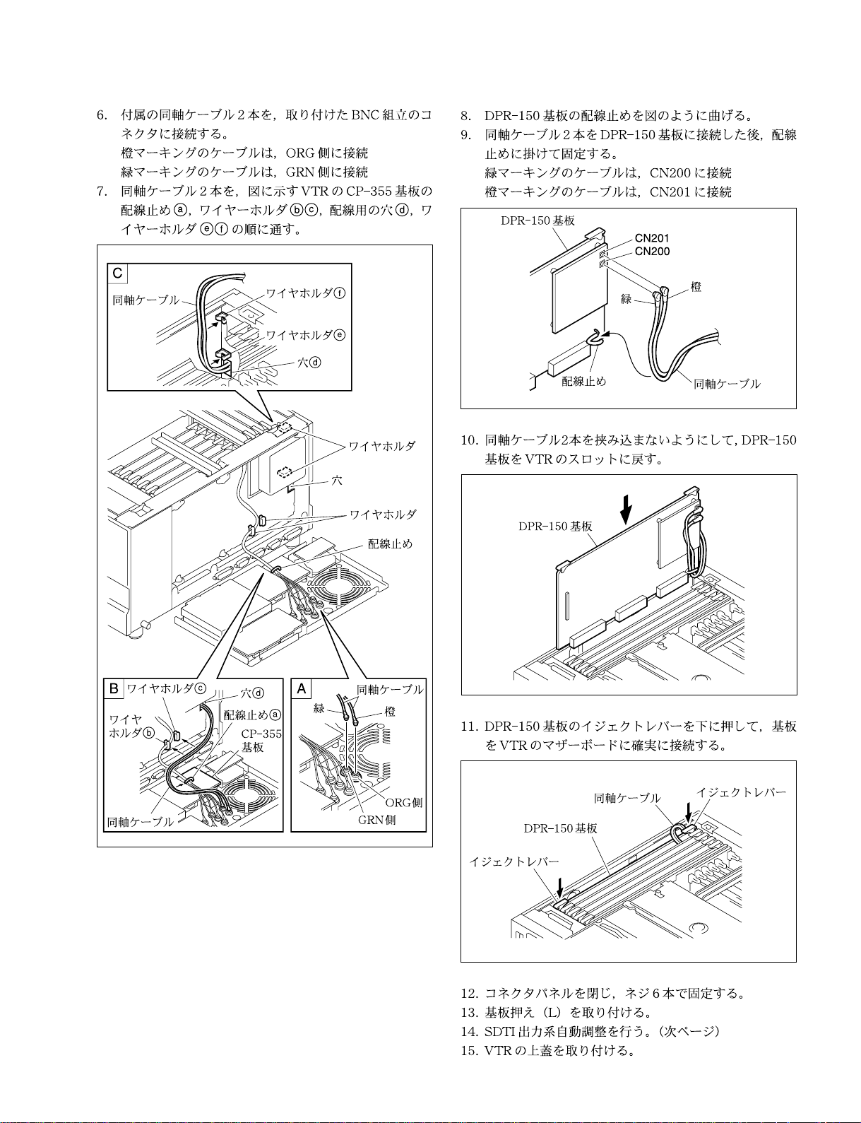
6. Connect the two supplied coaxial cables to
the connectors of the BNC assembly respectively.
Orange marked cable:Connect to ORG side.
Green marked cable: Connect to GRN side.
7. Let the two coaxial cables through in the
parts a to f order as shown in the figures.
C
Coaxial cables
Wire holder f
Wire holder e
Hole d
Wire holders
Hole
8. Bend the clamper on the DPR-150 board as shown in
the figure.
9. After connecting the two coaxial cables respectively
to CN200 (green) and CN201 (orange) on the DPR150 board, clamp and fix the cables with the clamper
on the DPR-150 board.
DPR-150 board
Clamper
Green
CN201
CN200
Orange
Coaxial cables
10. Reinsert the DPR-150 board (attached DPR-150
board) to the slot of DNW.
(Be careful not to pinch the cables by the boards.)
Wire holder c
Wire
holder b
Coaxial
cables
Hole d
Clamper a
CP-355
board
AB
Green
Wire holders
Clamper
Coaxial cables
Orange
GRN side
ORG
side
DPR-150 board
11. Push simultaneously down the two eject levers of the
DPR-150 board to firmly connect the board to the
motherboard of VTR.
Coaxial cables
DPR-150 board
Eject lever
Eject lever
BKNW-124
12. With the connector panel closed, fix the panel with
the six screws.
13. Reattach the board retainer (L).
14. Perform the SDTI output line automatic adjustment on
next page.
15. Reattach the upper lid of DNW.
3 (E)
Page 10

DNW’s maintenance mode
Electrical adjustment
Activating the maintenance mode
Press the switch S1101 (L-1) on the SS-83 board of DNW.
Selecting a mode or menu
With the *-mark set ahead of a mode (or menu) item
selected, press DNW’s SET button once.
To move the *-mark, turn DNW’s search dial (in JOG
mode).
Exiting a mode or menu
Press DNW’s MENU button once.
Change the adjustment mode
From Manual to Auto :
With the *-mark set ahead of “Manual”, turn the search
dial in FORWARD (2) direction while pressing the JOG
button.
Then the display on the video monitor changes to “Auto
(Push SET button)” from “Manual”.
In DNW’s time data display area, “PUSH SET” is
displayed.
Preparation
1. Connect the video monitor to the VIDEO OUTPUT
COMPOSITE 3 (SUPER) connector on the connector
panel of DNW.
2. Set on CHARACTER switch on the sub-control panel
of DNW.
3. Warm up DNW through the power for 10 minutes or
more.
Adjustment
1. Activate the maintenance mode.
2. Select M0 : TAPE MAINTENANCE.
3. Select A2 : AUDIO/VIDEO ADJUST.
4. Select A23 : SDI/SDTI VR.
5. Select A235 : SDTI-CP ENC VCO.
6. Change the adjustment mode from Manual to Auto.
7. Press the SET button once to execute the automatic
adjustment.
Then,
the displayed message on the video monitor changes to
“Auto Adjusting ...”. The displayed data value also
changes. But, the display in the time data display area
does not change. (“PUSH SET” in it remains displayed.)
8. Check the automatic adjustment completion on the
video monitor.
. When this automatic adjustment is completed, a
message “Auto Adjust Complete” will be displayed.
n
If message “Auto Adjust Failure” is displayed, the
DPR-150 board or the DIF-109 board is considered to
be defective.
9. Exit A235 : SDTI-CP ENC VCO.
10. Exit A23 : SDI/SDTI VR.
4 (E)
Data save (Store the adjusted data)
1. Select A2F : NV-RAM CONTROL.
2. Select SAVE ALL ADJUST DATA.
n
When this data save is completed normally, a message
“Save Complete” will be displayed on the video
monitor.
3. Press the MENU button four times to exit the maintenance mode.
4. Turn off the power of DNW.
BKNW-124
Page 11

The material contained in this manual consists of
information that is the property of Sony Corporation.
Sony Corporation expressly prohibits the duplication of
any portion of this manual or the use thereof for any
purpose other than the operation or maintenance of the
equipment described in this manual without the express
written permission of Sony Corporation.
Le matériel contenu dans ce manuel consiste en
informations qui sont la propriété de Sony Corporation.
Sony Corporation interdit formellement la copie de
quelque partie que ce soit de ce manuel ou son emploi
pour tout autre but que des opérations ou entretiens de
l’équipement à moins d’une permission écrite de Sony
Corporation.
Das in dieser Anleitung enthaltene Material besteht aus
Informationen, die Eigentum der Sony Corporation sind.
Die Sony Corporation untersagt ausdrücklich die
Vervielfältigung jeglicher Teile dieser Anleitung oder den
Gebrauch derselben für irgendeinen anderen Zweck als
die Bedienung oder Wartung der in dieser Anleitung
beschriebenen Ausrüstung ohne ausdrückliche
schriftliche Erlaubnis der Sony Corporation.
BKNW-124
Page 12

BKNW-124 (SY) J, E
3-204-009-03
Printed in Japan
Sony Corporation 2001. 6 08
B&P Company ©2000
 Loading...