

Page 1

NETWORK INTERFACE BOARD
BKMW-E3000
OPERATION MANUAL [English]
1st Edition
Page 2

For the customers in the USA
This equipment has been tested and found to comply with the
limits for a Class A digital device, pursuant to Part 15 of the
FCC Rules. These limits are designed to provide reasonable
protection against harmful interference when the equipment is
operated in a commercial environment. This equipment
generates, uses, and can radiate radio frequency energy and,
if not installed and used in accordance with the instruction
manual, may cause harmful interference to radio
communications. Operation of this equipment in a residential
area is likely to cause harmful interference in which case the
user will be required to correct the interference at his own
expense.
You are cautioned that any changes or modifications not
expressly approved in this manual could void your authority to
operate this equipment.
The shielded interface cable recommended in this manual
must be used with this equipment in order to comply with the
limits for a digital device pursuant to Subpart B of Part 15 of
FCC Rules.
This device complies with Part 15 of the FCC Rules. Operation
is subject to the following two conditions: (1) this device may
not cause harmful interference, and (2) this device must
accept any interference received, including interference that
may cause undesired operation.
For customers in Canada
This Class A digital apparatus complies with Canadian ICES-
003.
For the customers in Europe
This product with the CE marking complies with the EMC
Directive(89/336/EEC) issued by the Commission of the
European Community.
Compliance with this directive implies conformity to the
following European standards:
• EN55103-1: Electromagnetic Interference(Emission)
• EN55103-2: Electromagnetic Susceptibility(Immunity)
This product is intended for use in the following
Electromagnetic Environment(s):
E1 (residential), E2 (commercial and light industrial),
E3 (urban outdoors) and E4 (controlled EMC environment, ex.
TV studio).
Warning
This unit must be installed by qualified service personnel only.
Incorrect installation may cause a fire, electrical shock, or
other accident, resulting in personal injury or property
damage.
Note to service personnel installing the board
Refer to the installation manual supplied with the BKMWE3000 for installation instructions.
NOTICE TO USERS
© 2004 Sony Corporation. All rights reserved. This manual or
the software described herein, in whole or in part, may not be
reproduced, translated or reduced to any machine readable
form without prior written approval from Sony Corporation.
SONY CORPORATION PROVIDES NO WARRANTY WITH
REGARD TO THIS MANUAL, THE SOFTWARE OR OTHER
INFORMATION CONTAINED HEREIN AND HEREBY
EXPRESSLY DISCLAIMS ANY IMPLIED WARRANTIES OF
MERCHANTABILITY OR FITNESS FOR ANY PARTICULAR
PURPOSE WITH REGARD TO THIS MANUAL, THE
SOFTWARE OR SUCH OTHER INFORMATION. IN NO
EVENT SHALL SONY CORPORATION BE LIABLE FOR
ANY INCIDENTAL, CONSEQUENTIAL OR SPECIAL
DAMAGES, WHETHER BASED ON TORT, CONTRACT, OR
OTHERWISE, ARISING OUT OF OR IN CONNECTION
WITH THIS MANUAL, THE SOFTWARE OR OTHER
INFORMATION CONTAINED HEREIN OR THE USE
THEREOF.
Sony Corporation reserves the right to make any modification
to this manual or the information contained herein at any time
without notice.
The software described herein may also be governed by the
terms of a separate user license agreement.
2
Page 3

Table of Contents
Overview ................................................................................ 5
e-VTR Functions ........................................................................5
e-VTR Manager Application Software Functions......................6
System Configuration .................................................................7
Preparations .......................................................................... 9
For Using a Computer ................................................................9
Basic Network Settings...............................................................9
Setting the Tape Top and the Beginning of the File.................11
Viewing the Network Settings..................................................11
Enabling File Reception when Using a Cassette without a
Memory Label .................................................................12
Enabling the REC Command via a Network for a Cassette with a
Memory Label .................................................................13
Enabling File Creation Exceeding the Capacity of a Memory
Label................................................................................13
Applying Changes to Basic Network Settings..........................14
Resetting User Names and Passwords......................................15
Setting the Maximum Transfer Rate.........................................15
Setting the Transfer Processing for Nonrecorded Sections ......16
Copying the Timecode Recorded in the Source Cassette.........16
Selecting the Output Audio Channel of e-Monitor...................16
Enabling File Transfer Through Control Panel Operation .......17
Starting e-VTR Manager...................................................... 19
e-VTR Manager Window Menus .............................................20
e-VTR Manager Window Tool Buttons ...................................20
Registering e-VTRs ............................................................. 21
Outputting Device Register Information to a File ....................21
Registering the Device Information at a Time by Reading a File
22
Accessing e-VTRs From the Computer....................................22
VTR Window Configuration................................................ 24
Entering the Title and ID of a Cassette (under Superuser
Privilege) .........................................................................26
Setting the Directory Path on the External Metadata Server
(under Superuser Privilege).............................................26
Manipulating the File System Data on an External Server (under
Superuser Privilege) ........................................................27
Creating Files (under Superuser Privilege)....................... 28
Creating Record Entries............................................................28
Importing/Exporting File List...................................................29
Automatically Creating Files from Tape or Memory Label
Information......................................................................30
Table of Contents
3
Page 4

Backing Up the Menu Settings.................................................30
Saving the Files with a Different Name ...................................30
Monitoring File Contents .................................................... 31
Displaying File Top Pictures ....................................................31
Monitoring the Video and Audio of Files (e-monitor) .............31
Storing JPEG Data....................................................................31
Storing/Playing Files Using a PC....................................... 32
Storing an MXF Proxy AV File on the PC Local Disk ............32
Playing Back a MXF Proxy AV File on the PC Local Disk ....32
Transferring Files ................................................................33
File Transfer Progress Window Operations .............................33
If the Receiving Side Has a File of the Same Name With the File
Being Transferred............................................................34
Changing File Attributes (Change Attribute) ...........................34
Web Application Operations .............................................. 35
Displaying the Web Application ..............................................35
Information in the Top Page .....................................................36
File Page Operations........................................................... 37
Displaying and Modifying Attributes of Existing Files ...........38
Updating the Content of File and Entry Record Lists ..............38
Capturing Images......................................................................38
Creating Files............................................................................38
Creating Record Entries............................................................38
Maintenance Page Operations ........................................... 39
Hours Meter Page .....................................................................40
Error Logger Page.....................................................................41
User Registration Page .............................................................42
SNMP Variable Settings Page..................................................44
Network Information Page .......................................................45
MENU Information for Network Page .....................................45
MXF D10 Transfer Destination Page .......................................46
MXF Proxy AV Transfer Destination Page..............................47
DNS Server & HTTP Proxy Server Page .................................48
Table of Contents
4
Page 5

Overview
The BKMW-E3000 is a network interface board for
installation in an MSW-2000 series digital videocassette
recorder. With this board installed, the VTR can be added
to a 10/100/1000Base-T network to transfer video, audio,
and metadata as MXF files. You can use MXF data
received over the network to record video, audio, and
metadata to cassettes. MXF (Material Exchange Format) is
a file format that stores video, audio, and metadata in a
single package. It enables communications between
network devices such as VTRs and servers.
Windows application network services
Installing e-VTR Manager, the supplied Windows
application, allows FTP file transfer and monitoring of
video and audio from the application.
Using the e-VTR control panel to transfer
FTP/HTTP files
You can use the control panel operation of the e-VTR
instead of the supplied Windows application e-VTR
Manager to transfer FTP or HTTP files. If you specify IN
and OUT points in advance, you can then transfer the
section between the points as a file. Up to 5 servers can be
registered as transfer destinations. These destination
settings are saved even after the power to the VTR is turned
off.
e-VTR Functions
A VTR with this board installed (called an e-VTR below)
provides the following functions in addition to functions
provided by standard MSW-2000 series VTR.
MXF file transfer and reception (file
management)
MXF files containing video, audio, and metadata can be
sent and received over a network (using FTP protocol).
MXF Proxy AV file transfer
You can store low-resolution video, audio, and metadata as
an MXF file and handle the file at a low transfer rate. Files
that contain such low-resolution video and audio data are
called “MXF Proxy AV files.” MXF Proxy AV files are
played back using the supplied Windows application
software e-VTR Manager.
Copying of timecode from the source
material
Timecode (LTC) from the source tape in the transmitting
VTR can be copied as is to the cassette tape in the receiving
VTR. The Setup menu of the receiving VTR (ITEM-252:
TCG NETWORK REGEN MODE) can be used to specify
whether the timecode is regenerated or copied as is from
the source tape.
e-monitor functions
Video and audio can be monitored on a computer screen.
Video is sent from the e-VTR using JPEG compression,
and audio is sent using A-Law compression.
Network transmission data rate limitations
Limitations can be placed on data transmission rates for
transmissions from the e-VTR to the network. This can
prevent congestion and severe degradation in performance
when the network is busy.
Automatic acquisition of IP addresses and
other network settings
Network settings for the e-VTR (IP address, subnet mask,
default gateway) can be automatically acquired from a
DHCP server when the VTR is turned on and the VTR set
according to the information. In order to utilize this
function, it is necessary to install a DHCP server or a
DHCP relay agent on the same network as the e-VTR.
Network operation using a host name
(DNS client function)
When connecting with external devices via network,
operations can be achieved using the host names as well as
the IP addresses. Specifying a server to be connected by
its host name pemits the server to be easily identified.
Web server network services
Internet browsers such as Internet Explorer and Netscape
Navigator can be used for the following operations:
• File operations
• Displaying the hours meter
• Displaying the error logger list
• SNMP (Simple Network Management Protocol) settings
• Displaying network information
• Displaying menus for network operations
File jump function
When the tape already contains data defined as MXF files,
you can jump between neighboring files and play the files
back.
Automatic creation of MXF files from tape
or memory label information
MXF files can be automatically created from information
in the timecode (LTC) on the tape (rec start marks, shot
marks, post marks) or from information recorded on the
Overview
5
Page 6

memory label (rec start marks, shot marks, cue points, IN/
OUT points).
User registration
Up to 5 users can be registered for one e-VTR.
One of the registered users is “superuser,” and the other
users are “general users,” registered by the superuser.
The privileges of the users are as follows:
e-VTR Manager Application Software Functions
The supplied e-VTR Manager application software can be
installed on a computer connected to the e-VTR to enable
control of the e-VTR from the computer.
The software provides the following functions.
Superuser
• Can register general users.
• Can view video and audio recorded at any location on
cassette tapes.
• Can create files at any location on cassette tapes.
• Can change the properties of files owned by all users.
General users
• Can change own password.
• Can view file segments in files to which the user has
access privileges.
• Can modify attributes of files for which the user has
attribute modification privileges.
The superuser registers general users on the user
registration page of the Web application (see page 42).
General users can use the same page to change their own
passwords.
Backing up Setup menu settings
Setup menu settings of the e-VTR can be saved to the
computer via a network. The saved file can then be used to
recover settings or copied to other e-VTRs.
SNMP (Simple Network Management
Protocol) function
The SNMP function allows management information on
network devices (i.e., the e-VTR) to be monitored from
external monitoring software. SNMP settings for each eVTR on the network can be made through the maintenance
screen of the Web browser.
External server link of metadata
A meta-data file in an external server can be downloaded
and stored with video and audio data as a single MXF file
enabling file transmission. You can thus operate metadata
under external control and video/audio data recorded on
tapes in collaboration.
MXF file transfers between FTP servers,
including the e-VTR
The application can control MXF file transfers between eVTRs and between e-VTRs and servers, You can register
multiple network devices on a single computer and control
the devices individually.
e-VTR file creation, modification, and
deletion
Files can be created by defining the top and end of
previously recorded sections on the tape. These files can be
modified and deleted.
e-VTR video and audio monitoring
The contents of video and audio files on the e-VTR can be
monitored in real time on the computer. You can create
files while checking video and audio.
Storage and playback of MXF Proxy AV
files
You can load MXF Proxy AV files from an e-VTR to a
local disk of your PC. It is also possible to play back MXF
Proxy AV files stored on the local disk.
Trademarks
• Windows is a registered trademark of Microsoft Corporation in
the United States and/or other countries.
• Netscape is a registered trademark of Netscape
Communications Corporation in the United States and/or other
countries.
Automatic file-system data operations with
an external server
Information regarding the file system is normally stored in
the Tele-File. You can set your e-VTR to write and
automatically read these data to/from an external server.
This permits you to specify many files regardless of the
Tele-File capacity.
Overview
6
Page 7
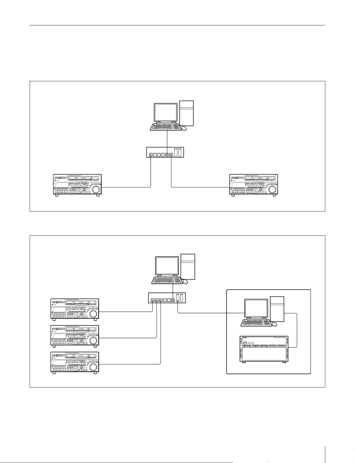
System Configuration
The following figures show examples of network systems
using e-VTRs.
Connecting two e-VTRs
Computer
Z Z
e-VTR 1 e-VTR 2
Hub
Connecting multiple e-VTRs and a server
Computer
Z
Z
Z
e-VTRs
Hub
Server
Overview
7
Page 8
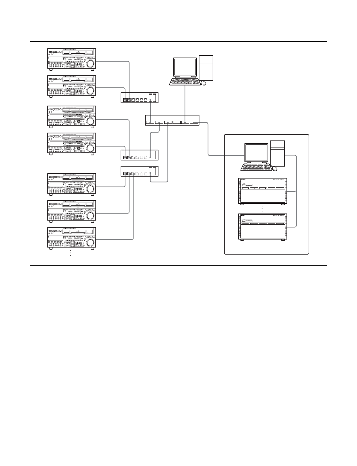
Connecting multiple e-VTRs and a mass storage server
Z
Z
Computer
Hub
Z
Rooter
Z
Hub
Hub
Z
Z
Z
e-VTRs
Mass storage server
8
Overview
Page 9
Preparations
3
Rotate the MULTI CONTROL knob to bring the
cursor (*) to M5: NETWORK and press the F5 (SET)
button.
For Using a Computer
Install e-VTR Manager on a computer meeting the
following requirements.
e-VTR Manager may not perform normally if installed on
a computer that does not meet these requirements.
CPU: 1 GHz or higher
Memory: 256 MB or greater
OS: Windows XP/2000
DirectX 8.1lb or higher
Language: English
Available hard disk space: 5 MB or more
Monitor resolution: XGA (1024 × 768) or more
recommended
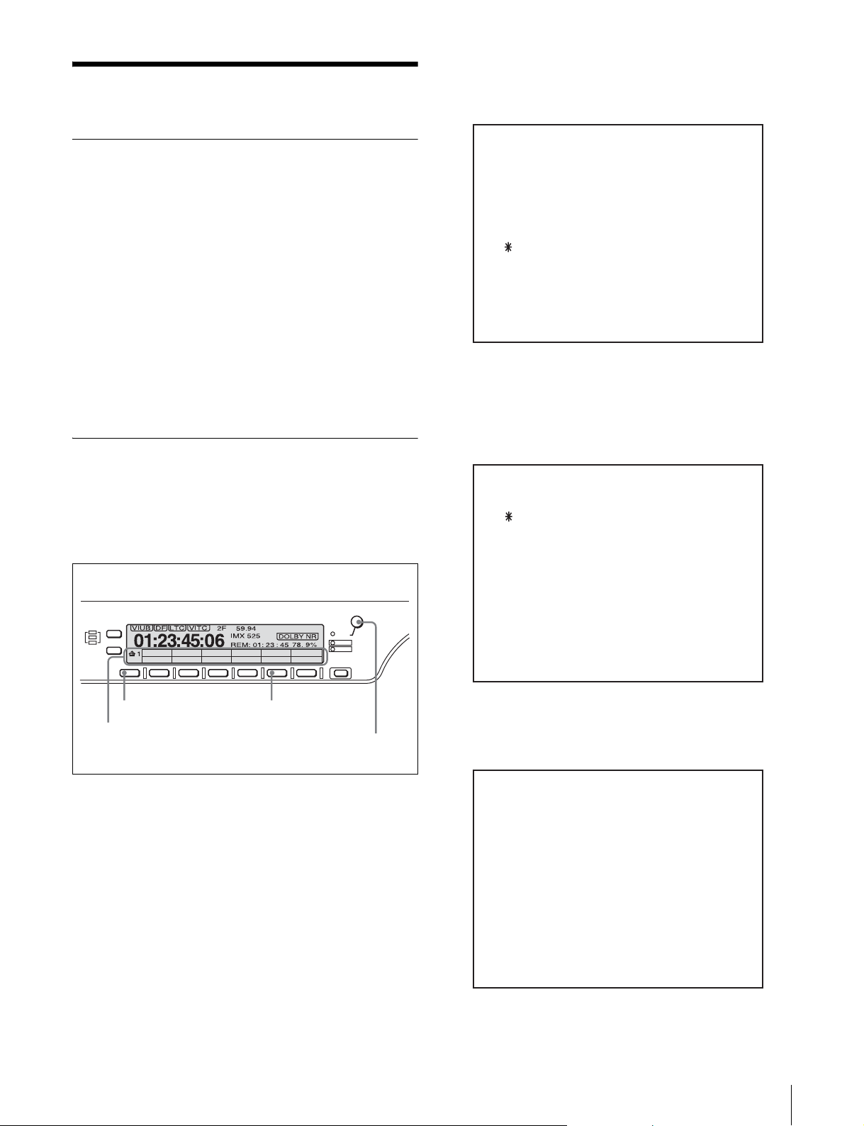
Basic Network Settings
Use the VTR maintenance menu to make basic network
settings.
Use the following procedure to set the IP address, subnet
mask, and default gateway.
VTR control panel
MULTI
CONTROL
PUSH/
SHIFT
ALARM
CHANNEL
CONDITION
CTL/TC
F1 F2 F3 F4 F5 F6
HOME
TC
MENU
KEY INHI
RESET
MAINTENANCE MODE
M0 : CHECK
M1 : ADJUST
M2 : ERROR LOGGER
M3 : OTHERS
M4 : SETUP MAINTENANCE
M5 : NETWORK
The M5: NETWORK page appears.
4
Rotate the MULTI CONTROL knob to bring the
cursor to M50: IP ADDRESS and press the F5 (SET)
button.
M5 : NETWORK
M50 : IP ADDRESS
M51 : SUBNET MASK
M52 : DEFAULT GATEWAY
M55 : TAPE LEADER CONFIG
M56 : IP CONFIG
M57 : OTHERS CONFIG
M58 : M50-M52 RENEW
M59 : RESET ALL USER
HOME button
HOME page of function menu
1
On the VTR control panel, display the HOME page of
F5(MENU) button
MULTI CONTROL knob
the function menu.
2
With the HOME button pressed, press the F5 (MENU)
button to open the MAINTENANCE MODE page.
The M50: IP ADDRESS setting page appears.
5
Enter a new value or change the present value.
M5 : NETWORK
M50 : IP ADDRESS
192. 168. 0. 123
Preparations
9
Page 10

To bring the cursor to the value you want to change
Rotate the MULTI CONTROL knob.
To change a value
Rotate the MULTI CONTROL knob while holding the
HOME button down.
To set the default gateway
Bring the cursor to M52: DEFAULT GATEWAY in
step 4.
8
Restart the e-VTR, or operate M58: M50-M52
RENEW to apply the changes to the network settings.
For automatic assignment of network settings (such
as IP address)
Set the IP address to “000.000.000.000” or
“255.255.255.255.”
When the e-VTR is turned on, the network settings are
automatically assigned.
Notes
• If the IP address is set to “000.000.000.000” or “255.
255.255.255,” the IP address, subnet mask, and
default gateway are automatically assigned. In this
case, step 7 below is unnecessary.
• If automatic assingment is active, M51: SUBNET
MASK and M52: DEFAULT GATEWAY are not
displayed.
• For automatic assignment of network settings, a
DHCP server or a DHCP relay agent must be
installed on the same network as the e-VTR.
• If network settings are automatically assigned, the IP
address may change whenever the e-VTR is
restarted. To prevent this, the IP address for the
hardware address of the e-VTR should be defined in
advance on the DHCP server. The hardware address
can be confirmed on the Network Interface page
(see page 45) of the Web application.
Checking the state of the network
The network indicator lights or goes out as follows,
according to the state of the network.
Not lit: No FTP connection
Lit: FTP control connection
Blink: FTP data connection
NETWORK button
Full access to the network is possible when the
NETWORK button is lit. When the NETWORK button is
not lit, limited network access is permitted for the
functions indicated below.
• Access via link layer (ping response, etc.)
• Web browsing
6
When you have set the value, press the F5 (SET)
button.
The message “Save Complete” appears.
M5 : NETWORK
M50 : IP ADDRESS
192. 168. 0. 123
Save Complete
7
Set the subnet mask and default gateway in the manner
which is explained in steps 4 to 6.
To set the subnet mask
Bring the cursor to M51: SUBNET MASK in step 4.
10
Preparations
Page 11

Setting the Tape Top and the Beginning of the File
You can specify the length of the leader section at tape top,
the timecode at the start of the recordable portion, and the
type of video signal recorded on the leader section.
Tape top
Leader
section
1
Do steps 1 to 3 of “Basic Network Settings” (see page
9) to display the M5: NETWORK page of the
maintenance menu.
Starting timecode
Header
section
Video signal type
File contents
M550: LEADER LENGTH: Sets the length of the
leader section at tape top. The default setting is 10
seconds.
M551: LEADER TC: Sets the timecode at the start of
the recordable portion of the tape. The default
setting is “00:00:00:00.”
M552: LEADER SIGNAL: Sets the type of signal
recorded on the leader section of the tape and the
start of each file. The default setting is “OFF”
(black burst).
3
Rotate the MULTI CONTROL knob to bring the
cursor (*) to the item to be set, and then press the F5
(SET) button.
4
Rotate the MULTI CONTROL knob to change the
setting, and then press the F5 (SET) button.
The message “Save Complete” appears.
2
Rotate the MULTI CONTROL knob to bring the
cursor (*) to M55: TAPE LEADER CONFIG, and then
press the F5 (SET) button.
M5 : NETWORK
M50 : IP ADDRESS
M51 : SUBNET MASK
M52 : DEFAULT GATEWAY
M55 : TAPE LEADER CONFIG
M56 : IP CONFIG
M57 : OTHERS CONFIG
M58 : M50-M52 RENEW
M59 : RESET ALL USER
The sub-page for M55: TAPE LEADER CONFIG
appears.
M5 : NETWORK
M550: LEADER LENGTH
M551: LEADER TC
M552: LEADER SIGNAL
Viewing the Network Settings
You can use the maintenance menu to list the following
network settings.
• Setting for automatic acquisition of IP address
• Whether the internet proxy is used or not
• IP address assigned to the e-VTR
• Subnet mask for the connected network
• IP address of the default gateway of the connected
network
• IP address of the DNS server
1
Do steps 1 to 3 of “Basic Network Settings” (see page
9) to display the M5: NETWORK page of the
maintenance menu.
2
Rotate the MULTI CONTROL knob to bring the
cursor (*) to M56: IP CONFIG, and then press the F5
(SET) button.
M5 : NETWORK
M50 : IP ADDRESS
M51 : SUBNET MASK
M52 : DEFAULT GATEWAY
M55 : TAPE LEADER CONFIG
M56 : IP CONFIG
M57 : OTHERS CONFIG
M58 : M50-M52 RENEW
M59 : RESET ALL USER
A list of network-related settings appears.
Preparations
11
Page 12

M5 : NETWORK
M56 : IP CONFIG
3
Rotate the MULTI CONTROL knob to bring the
cursor (*) to M570: REC WITHOUT TELE-F, and
then press the F5 (SET) button.
DHCP:disable
IP ADDRESS:
192.168.000.001
SUBNET MASK:
255.255.255.000
DEFAULT GATEWAY:
192.168.000.254
DNS SERVER ADDRESS:
192.168.000.254
Enabling File Reception when Using a Cassette without a Memory Label
It is normally necessary to attach a memory label to a
cassette to enable FTP file reception. Follow the procedure
to below enable FTP file reception when using a cassette
without a memory label.
Note
In the case of a cassette without a memory label, recording
of a file by the e-VTR begins from the tape position at the
time the FTP command is received. Keep in mind that all
material after that point will be overwritten by the received
file.
OTHERS CONFIG
M570: REC WITHOUT TELE-F
M571: REC WITH TELE-F
M572: TEMP FILE CREATE
The M570: REC WITHOUT TELE-F setting page
appears.
4
Rotate the MULTI CONTROL knob to change the
setting.
OTHERS CONFIG
M570: REC WITHOUT TELE-F
disable
1
Do steps 1 to 3 of “Basic Network Settings” (see page
9) to display the M5: NETWORK page of the
maintenance menu.
2
Rotate the MULTI CONTROL knob to bring the
cursor (*) to M57: OTHERS CONFIG, and then press
the F5 (SET) button.
M5 : NETWORK
M50 : IP ADDRESS
M51 : SUBNET MASK
M52 : DEFAULT GATEWAY
M55 : TAPE LEADER CONFIG
M56 : IP CONFIG
M57 : OTHERS CONFIG
M58 : M50-M52 RENEW
M59 : RESET ALL USER
The sub-page for M57: OTHERS CONFIG appears.
Push SET button
enable: Recording of transferred files is enabled even
when cassettes inserted in the e-VTR have no
memory labels.
disable (default setting): Recording of transferred
files is disabled for cassettes inserted in the e-VTR
with no memory labels.
5
Press the F5 (SET) button.
The message “Save Complete” appears.
12
Preparations
Page 13

Enabling the REC Command via a Network for a Cassette with a Memory Label
OTHERS CONFIG
M571: REC WITH TELE-F
Execution of the REC command via a network when using
a cassette with a memory label attached is normally
disabled to prevent overwriting of a file that has been
already received.
However, you can execute the REC command via a
network for a cassette wtih a memory label in a case in
which no file has been created by any user.
1
Do steps 1 to 3 of “Basic Network Settings” (see page
9) to display the M5: NETWORK page of the
maintenance menu.
2
Rotate the MULTI CONTROL knob to bring the
cursor (*) to M57: OTHERS CONFIG, and then press
the F5 (SET) button to display the sub-page.
3
Rotate the MULTI CONTROL knob to bring the
cursor (*) to M571 REC WITH TELE-F, and then
press the F5 (SET) button.
OTHERS CONFIG
M570: REC WITHOUT TELE-F
M571: REC WITH TELE-F
M572: TEMP FILE CREATE
enable
Push SET button
enable: If no file has been created, execution of the
REC command execution is enabled even if the
cassette inserted in the e-VTR has a memory label.
disable (default setting): REC command execution is
disabled for any cassette inserted in the e-VTR that
has a memory label.
5
Press the F5 (SET) button.
The message “Save Complete” appears.
Enabling File Creation Exceeding the Capacity of a Memory Label
Creation of a file exceeding the capacity ot the memory
label attached to the cassette is normally disabled.
With the following menu operation, you can enable
continuous file creation even after the capacity of the
memory label is exceeded. Note that the files to be created
after the capacity of the memory label is exceeded will be
temporary files.
The M571: REC WITH TELE-F setting page appears.
4
Rotate the MULTI CONTROL knob to change the
setting.
For the temporary files, see the description under “File
list” on page 25
1
Do steps 1 to 3 of “Basic Network Settings” (see page
9) to display the M5: NETWORK page of the
maintenance menu.
2
Rotate the MULTI CONTROL knob to bring the
cursor (*) to M57: OTHERS CONFIG, and then press
the F5 (SET) button to display the sub-page
3
Rotate the MULTI CONTROL knob to bring the
cursor (*) to M572: TEMP FILE CREATE, and then
press the F5 (SET) button.
Preparations
13
Page 14

OTHERS CONFIG
M570: REC WITHOUT TELE-F
M571: REC WITH TELE-F
M572: TEMP FILE CREATE
The M572: TEMP FILE CREATE setting page
appears.
4
Rotate the MULTI CONTROL knob to change the
setting.
OTHERS CONFIG
M572: TEMP FILE CREATE
enable
2
Rotate the MULTI CONTROL knob to bring the
cursor (*) to M58: M50-M52 RENEW and press the
F5 (SET) button.
M5 : NETWORK
M50 : IP ADDRESS
M51 : SUBNET MASK
M52 : DEFAULT GATEWAY
M55 : TAPE LEADER CONFIG
M56 : IP CONFIG
M57 : OTHERS CONFIG
M58 : M50-M52 RENEW
M59 : RESET ALL USER
The M58: M50-M52 RENEW page appears.
3
Rotate the MULTI CONTROL knob to set the setting
to ON.
M5 : NETWORK
M58 : M50-M52 RENEW
ON
Push SET button
enable: You can create files even after the capacity of
the memory label is exceeded. Files to be created
after the capacity of the memory label is exceeded
are temporary files.
disable (default setting): File creation is disabled
after the capacity of the memory label is exceeded.
5
Press the F5 (SET) button.
The message “Save Complete” appears.
Applying Changes to Basic Network Settings
After changing basic network settings, you can use M58:
M50-M52 RENEW to apply the changes without
restarting the e-VTR. Proceed as follows.
Push SET Button
4
Press the F5 (SET) button.
The message “Complete” appears.
M5 : NETWORK
M58 : M50-M52 RENEW
ON
Complete
14
1
Do steps 1 to 3 of “Basic Network Settings” (see page
9) to display the M5: NETWORK page of the
maintenance menu.
Preparations
Page 15

Resetting User Names and Passwords
M5 : NETWORK
M59 : RESET ALL USER
Use the VTR maintenance menu to reset registered user
names and passwords to the default.
Note
This procedure resets the names and passwords of all
registered users.
1
Do steps 1 to 3 in the procedure of “Basic Network
Settings” (see page 9) to display the M5: NETWORK
page of the maintenance menu.
2
With the HOME button pressed, rotate the MULTI
CONTROL knob to bring the cursor (*) to M59:
RESET ALL USER and press the F5 (SET) button.
M5 : NETWORK
M50 : IP ADDRESS
M51 : SUBNET MASK
M52 : DEFAULT GATEWAY
M55 : TAPE LEADER CONFIG
M56 : IP CONFIG
M57 : OTHERS CONFIG
M58 : M50-M52 RENEW
M59 : RESET ALL USER
ON
Complete
Turn off/on POWER !!
5
Restart the e-VTR.
Setting the Maximum Transfer Rate
You can reduce the load on the network by setting the
maximum transfer rate to the network by the sending side
e-VTR.
When required, change the setting using the Setup menu
ITEM-250: MAXIMUM RATE on the transmitting VTR.
For details on setup operation, refer to the Operation
Manual supplied with the VTR.
ITEM-250
MAXIMUM RATE
The M59: RESET ALL USER page appears.
3
Rotate the MULTI CONTROL knob while holding the
HOME button down to change the setting to ON.
M5 : NETWORK
M59 : RESET ALL USER
ON
Push SET Button
– – – – – – Caution – – – – – –
All the user name and
password settings will be
changed to factory default.
4
Press the F5 (SET) button.
The message “Complete Turn off/on POWER !!”
appears.
best effort
best effort (default setting): Send data at the maximum
possible transfer rate.
1 Mbps to 50 Mbps: Limit the data transfer rate to the
selected value.
Preparations
15
Page 16

Setting the Transfer Processing for
Copying the Timecode Recorded in
Nonrecorded Sections
When the material transfer range is from the tape top to the
tape end (transfer of the virtual file &whole.mxf), or from
the current position to the tape end (transfer of the virtual
file ¤t.mxf), you can stop the transfer automatically
when a nonrecorded section is played back continuously
for a specific length of time. This setting is effective when
you do not know the length of the material but want to
transmit from a specific position to the last point where
signals are recorded.
When required, change the setting using the Setup menu
ITEM-251: NO RF TIME on the transmitting VTR.
For details on setup operation, refer to the Operation
Manual supplied with the VTR.
ITEM-251
NO RF TIME
30 sec
the Source Cassette
To enable the timecode (LTC) on the source cassette in the
transmitting VTR to be recorded as-is to the cassette in the
receiving VTR, this must be set on the Setup menu ITEM252: TCG NETWORK REGEN MODE.
For details on setup operation, refer to the Operation
Manual supplied with the VTR.
ITEM-252
TCG NETWORK REGEN MODE
off
The setting range is from 5 sec to 30 sec. The default value
is 30 sec.
off (default setting): The recorded timecode is
regenerated by the timecode generator during
recording of video/audio signals transferred through
the network.
on: The timecode generator locks to the timecode of the
transmitting VTR and the timecode on the source tape
is copied as-is during recording of video/audio signals
transferred through the network.
Notes
• When recording signals through an interface external to
the network to which the VTR is connected, the recorded
timecode is generated on the receiving VTR in
accordance with the Function menu setting.
• When receiving files, files with regenerated timecode
and files for which original timecode is copied cannot be
recorded on the same tape.
Selecting the Output Audio Channel of e-Monitor
To change the output audio channel of e-monitor, a setting
must be made on the Setup menu ITEM-253: EMONITOR AUDIO SELECT on the VTR.
16
For details on setup operation, refer to the Operation
Manual supplied with the VTR.
Preparations
Page 17

ITEM-253
ITEM-254
E-MONITOR AUDIO SELECT
track 1/2
track 1/2 (default setting): Audio track channels 1 and 2
are output.
track 3/4: Audio track channels 3 and 4 are output.
track 5/6: Audio track channels 5 and 6 are output.
track 7/8: Audio track channels 7 and 8 are output.
Enabling File Transfer Through Control Panel Operation
To enable FTP or HTTP file transfer using the control
panel of the e-VTR without using the supplied Windows
application, e-VTR Manager, the information on the
transfer destination servers must be registered with the
Web pages.
MXF D10 DESTINATION NO.
1
1 to 5: Registration number of the server you registered in
the Web window (default setting: 1)
The registration number of the destination server for
MXF Proxy AV materials is to be selected using the
Setup menu ITEM-255: MXF PRX DESTINATION NO.
on the transmitting VTR.
ITEM-255
MXF PRX DESTINATION NO.
1
For the Web pages, see “MXF D10 Transfer Destination
Page” on page 46 and “MXF Proxy AV Transfer
Destination Page” on page 47.
After registration on the Web pages, select the registration
numbers of the destination servers of MXF D10 and MXF
Proxy AV transfers by operating the Setup menu from the
control panel.
For details on setup operation, refer to the Operation
Manual supplied with the VTR.
The registration number of the destination server for
MXF D10 materials is to be selected using the Setup
menu ITEM-254: MXF D10 DESTINATION NO. on the
transmitting VTR.
1 to 5: Registration number of the server you registered on
the Web page (default setting: 1)
To transfer files through the control panel
To transfer a file while playing back the tape or while
recording the input signal on the tape using the control
panel of the e-VTR, proceed as follows:
1
Display page 5 of the function menu on the menu
display section of the control panel, and press the F6
(TR_SEL) button repeatedly to select the type of files
to be transmitted.
OFF (default setting): No file transfer is executed.
D10: To send MXF D10 materials
Proxy: To send MXF Proxy AV materials
BOTH: To send both MXF D10 and MXF Proxy AV
materials (This is valid only if you specified an
FTP server for the destination.)
Preparations
17
Page 18

2
To send a file while playing back the tape, cue to the
position from where you wish the transfer to start then
press the PLAY button while holding the ENTRY
button pressed.
To send a file while recording the input signal on
the tape, simultaneously press the REC and PLAY
buttons while holding the ENTRY button pressed.
To specify the transmission size (duration)
for the HTTP server
When the destination is an HTTP server, it is necessary to
specify the duration of the material to be sent, using the
Setup menu ITEM-256: : HTTP TRANSFER DURATION
in advance.
The e-VTR starts to transfer data.
3
When the destination is an FTP server, press the
STOP button when playback or recording of the
portion to be transferred ends,
The file transmission operation is completed after the
portion stored in the buffer memory on the network
board has been completely transferred.
When the destination is an HTTP server,
transmission automatically ends when the duration
specified using the Setup menu ITEM-256: HTTP
TRANSFER DURATION has elapsed.
If you press the STOP button during transmission,
transmission is terminated, and the file created on the
destination server is erased.
To transfer a specified portion on the tape
as a file
1
Play back the tape and register the IN and OUT points
for the portion be transferred.
ITEM-256
HTTP TRANSFER DURATION
20 sec
20 sec, 40 sec, 60 sec, 90 sec, 120 sec, 150 sec, 180 sec:
Size (duration) of the material to be sent in seconds
(default setting: 20 sec)
2
Press the PLAY button while holding the ENTRY
button pressed.
The portion between the IN and OUT points is tranferred
as a file.
Note that this operation is not possible if F6 (TR_SEL) has
been set to BOTH.
Notes
• When sending both MXF D10 and MXF Proxy AV while
playing back the tape or sending an MXF D10 or MXF
Proxy AV signal while recording the input signal on the
tape, it must be guaranteed that the destination server
and the network are in sufficient conditions to send each
of material files in the actual time alloted.
If the bandwidth of the network is insufficient, and
transfer of the material is jammed, parts of data may be
lost, and the file may not conform to the MXF file
standards.
• MXF Proxy AV transmission is not possible if the Setup
menu ITEM-111: TSO/PLAY has been set to FEED.
Therefore, if you set F6 (TR_SEL) to Proxy or BOTH,
file transmission is disabled.
18
Preparations
Page 19

Starting e-VTR Manager
Start e-VTR Manager by double clicking on (e-VTR
Manager icon).
e-VTR Manager window
Menu bar
Tool bar
Network Device
Register window
The e-VTR Manager window shown below appears.
Status bar
The Network Device Register window also appears when
e-VTR Manager is started.
Use the Network Device Register to manage the devices
controlled by e-VTR Manager (see page 21).
Starting e-VTR Manager
19
Page 20

e-VTR Manager Window Menus
The menu bar in the e-VTR Manager window contains the
following menus.
Edit Entry
Opens the File Entry window to modify the file selected in
the VTR window or the record entry settings of the file.
You can change the top/end points of the file, add/delete
the record entries, and change the record entry positions.
File menu
Setup command: Allows settings to be made for file list
import and export and file transfer cancellation.
Exit commnd: Select to exit from e-VTR Manager.
View menu
Provides the following four commands.
Status Bar: Hides or displays the status bar.
Toolbar: Hides or displays the toolbar.
Device Register: Closes or opens the Network Device
Register window.
Refresh: Refreshes the VTR window (see page 24).
Window menu
Provides the following three commands.
Cascade: Arranges windows in cascade fashion.
Tile: Arranges windows without overlap.
Arrange icon: Neatly arranges minimized icons.
Help menu
Provides command about e-VTR Manager which displays
version information in a popup window.
Get Top Thumbnail Picture
In the VTR window, captures the thumbnail picture for the
selected file or record entry.
Preview Monitor
Opens the Preview Monitor window to monitor the
contents of the file or record entry selected in the VTR
window.
Change Attribute
Opens the File Attribute window to change file attributes.
Delete File
In the VTR window, deletes the selected file.
Simple Monitor
Opens the e-monitor (Simple Monitor) window to monitor
output from the e-VTR’s Video/Audio Output connector.
MXF Proxy AV Viewer
Opens the MXF Proxy AV Viewer window to monitor
video and audio of an MXF Proxy AV file stored on a local
disk of a PC.
e-VTR Manager Window Tool Buttons
The following tool buttons are available on the toolbar.
Create File & Entry
Get Top Thumbnail Picture
Change Attribute
Simple Monitor
MXF Proxy AV
Viewer
Delete File
Preview Monitor
Edit Entry
Create File & Entry
Opens the Input Filename window and File Entry window
at the same time to create a new file and record entry.
Starting e-VTR Manager
20
Page 21

Registering e-VTRs
In the Network Device Register window, register e-VTRs
to operate on by entering their names and host names or IP
addresses.
The system saves registered names and host names or IP
addresses and displays them again in the Network Device
Register window the next time you start e-VTR Manager.
Network Device Register window
Outputting Device Register Information to a File
Information you have registered in the Network Device
Register window can be output to a file on a local disk of
the PC.
If the Network Device Register window is not open
Select Device Register in the View menu.
Registration procedure
1
Click on the Add button in the Network Device
Register window to display the Add Device window.
2
In the Config Name field, enter the name of the eVTR. In the HOST/IP Address field, enter the host
name or an IP address, then click on the OK button.
The newly entered name and host name or IP address
appear in the Network Device Register window.
You do not necessarily have to enter a name in Config
Name field. If you do not enter a name, the system uses the
name entered as the host name or the IP address.
1
Right-click in an empty area of the Network Device
Register window, and select Export from the popup
menu.
The filename entry window opens.
2
Enter the filename under which data to be stored, then
click on the Save button.
Information registered by the Network Device Register is
stored on a local file of the PC.
Registering e-VTRs
21
Page 22

Registering the Device Information
Accessing e-VTRs From the
at a Time by Reading a File
By reading a file from the PC local disk, you can make
registration of device information at a time.
1
Right-click in an empty area of the Network Device
Register window, and select Import from the popup
menu.
The file selection window opens.
2
Select the desired file, then click on the Open button.
Information is loaded to the Network Device Register from
the PC local file.
Computer
Use the following procedure to initiate communications
with an e-VTR to be controlled from the computer.
1
Select the e-VTR that you want to access from among
the e-VTRs in the Network Device Register window,
and double click it or click on the OPEN button.
The DirectLogin window appears.
2
If you want to use files on the VTR or operate the
VTR, enter your user name and password.
If you do not need to use files or operate the VTR but
simply want to use e-monitor functions, check the
Simple Monitoring check box. The Simple Monitoring
function is available only to a superuser. General users
do not have the authorization to use this function.
To register a user name and password
Register a user name on the registration Web page (see
page 42).
3
Click on the OK button.
The user is verified, and the e-VTR Manager window
opens (see next page). The window’s title is the name of
the selected e-VTR.
Registering e-VTRs
22
Page 23

e-VTR Manager window
VTR window
If you checked Simple Monitoring, the Simple Monitor
window appears.
In the Simple Monitor window, you can monitor the video
output from the e-VTR’s Video Output connector. You
cannot control the VTR or do any file operations.
Simple Monitor window
Registering e-VTRs
23
Page 24

VTR Window Configuration
The VTR window displays system information for the eVTR currently being controlled, and the data contents of
the cassette loaded in the e-VTR.
Notes
• The cassette data contents displayed in this window is
for data defined as files.
System information Top-of-file picture display
Refresh button
File display mode list
Metadata Directory indication
• The only files displayed are those which can be
manipulated by users. Files which cannot be viewed or
transferred do not appear.
• When the user is a superuser, the virtual files &whole
and ¤t are displayed in addition to normal files.
The following figure shows the VTR window.
File System indication
Cassette Title/ID indication
System information
This section displays the following information about the
e-VTR being controlled.
Item
System Frequency 525 (29.97): 525 lines/29.97 Hz
Cassette Size S-32: S cassette 32 min.
PB Format (cassette
playback format)
Rec Format MX: MPEG IMX
Tele-File Used (percent
usage of Tele-File)
Tape Use (percent
usage of tape)
Display example
625 (25): 625 lines/25 Hz
L-124: L cassette 124 min.
Analog: Analog Betacam
SX: Betacam SX
IMX: MPEG IMX
Digi-β: Digital Betacam
25%
48%
File list
Item
Rec Inhibit (on or off) ON: RECINH ON
Time Code Generator
(operation mode of the
timecode generator)
Display example
OFF: RECINH OFF
INTERNAL: The timecodes on the
tape are regenerated.
NETWORK: The original
timecodes of received materials
are copied.
Top-of-file picture display
This area shows a top-of-file picture for the file currently
selected in the file list. The picture is stored on the
computer as a temporary JPEG file until you exit the
application or eject the tape that contains the data for the
file.
Refresh button
Click on this button to refresh the VTR window.
VTR Window Configuration
24
Page 25

File display mode list
Select the type of files shown in the file list.
Normal (default): Display MXF file for which the user
has access privileges and which can be transferred
between e-VTRs. (Files whose names do not begin
with &. Among virtual files, &whole and ¤t.)
To ta l: Displays all files for which the user has access
privileges.
Proxy : Displays MXF Proxy AV files for which the user
has access privileges.
Metadata Directory indication
Displays the path of the directory under which metadata
have been accumulated.
The superuser can change the path.
For details, see“Setting the Directory Path on the External
Metadata Server (under Superuser Privilege)” on page 26.
File system indication
Displays where the file system data (file list) to be
manipulated.
: Memory labels on the cassettes
: External server
For details, see “Manipulating the File System Data on an
External Server (under Superuser Privilege)” on page 27.
CassetteTitle/ID indication
Displays the title and ID of the cassette, which can be
changed by the superuser.
For details, see“Entering the Title and ID of a Cassette
(under Superuser Privilege)” on page 26.
File list
Displays the files in the tape, in the order in which they are
recorded. The last file (data closest to the end of the tape)
is displayed in red. Another file can be appended after this
file.
There are 4 types of files: real files, temporary files, import
files, and virtual files.
Real files: These are files with information stored in a
Tele-File. They are permanent files which remain after
the power is turned off and after the tape is ejected.
Temporary files: These are files without information
stored in a Tele-File. They are discarded when the
power is turned off or the tape is ejected.
Import files: These are files temporarily created to hold
imported file information. They are discarded when
the power is turned off or the tape is ejected.
Virtual files: These are files created automatically
whenever the power is turned on and whenever a
cassette is loaded.
Virtual files are classified as follows:
File name Definition Operation in VTR
&whole.mxf MXF file over the
range from tape top
to tape end
¤t.mxf MXF file over the
range from current
tape position to tape
end
&xxxx_s.mxf MXF file consisting
of first frame in file.
&xxxx_e.mxf MXF file consisting
of last frame in file.
img.jpg File containing
JPEG picture
corresponding to
one frame of signals
output from e-VTR’s
VIDEO OUTPUT
connector.
&menu File containing the
contents of the eVTR Setup menu.
&wholeS01.mxf MXF Proxy AV file
over the range from
tape top to tape end
¤tS01.mxf MXF Proxy AV file
over the range from
current tape position
to tape end
&xxxxS01.mxf MXF Proxy AV file
that handle lowresolution video and
audio of a real file
&monitorM.mxf MXF D10 file
containing signal
output from e-VTR’s
VIDEO/AUDIO
OUTUT connector in
an MXF file
maintaining high
resolution
window
Shown only to
superuser.
Can be transferred
to e-VTR or FTP
server.
Shown only to
superuser.
Can be transferred
to e-VTR or FTP
server.
Shown only to
user with access
privileges.
Can be transferred
to e-VTR or FTP
server.
Shown only to
user with access
privileges.
Can be transferred
to e-VTR or FTP
server.
Can be transferred
to FTP server only.
Shown only to
superusers.
Can be saved to
the PC or
transferred to
another FTP
server.
Shown only to
superuser.
Can be transferred
to FTP server only.
Shown only to
superuser.
Can be transferred
to FTP server only.
Shown only to
user with access
privileges.
Can be transferred
to FTP server only.
Shown only to
superuser. Can be
transferred to eVTR and FTP
server.
VTR Window Configuration
25
Page 26

File name Definition Operation in VTR
window
&monitorS01.mxf MXF Proxy AV file
containing signal
output from e-VTR’s
VIDEO/AUDIO
OUTUT connector in
an MXF file after
converting to low
resolution
Shown only to
superuser. Can be
transferred to FTP
server only.
Entering the Title and ID of a Cassette (under Superuser Privilege)
When the cassette in the e-VTR has a memory label, a title
and an ID can be assigned to the cassette and registered.
The title and ID are displayed under the top-of-the file
display in the VTR window.
3
Click on the OK button.
Setting the Directory Path on the External Metadata Server (under Superuser Privilege)
The e-VTR permits metadata to be stored on an external
server, read from the server and inserted in an MXF file to
send with video and audio data when executing file
transmission.
The path of the directory under which the metadata have
been stored is displayed in the Metadata Directory
indication field in the VTR window.
Metadata Directory indication
Cassette Title/ID
indication
The superuser can change the title and ID.
Changing procedure
1
Double-click on the Cassette Title/ID indication field
to open the Cassette Information window. (The
window can also be opened by right-clicking in an
empty area of the file list and selecting Cassette
Information from the popup menu.)
2
Select the Title&ID tab and enter the desired title and
ID.
Up to 24 alphanumetic characters can be entered for
the title, and up to 20 alphanumetic characters can be
entered for the ID.
The superuser can change the directory setting.
Changing procedure
1
Double-click on the Metadata Directory indication
field to open the Cassette Information window. (The
window can also be opened by right-clicking in an
empty area of the file list and selecting Cassette
Information from the popup menu.)
2
Select the Metadata tab and set the data.
Metadata Link: Check this check box to use the
metadata link with an external server.
ftp/http: Click on either button to select the protocol
(FTP or HTTP) for accessing to the server.
Directory Path: Specify the directory path starting
with the host name.
User Name for FTP/HTTP Server, Password for
FTP/HTTP Server: When recognition with a user
name and a password is required when accessing to
VTR Window Configuration
26
Page 27

the server, enter the appropriate user name and
password.
3
Click on the OK button.
On this tab, enter the path for the directory under which the
metadata have been stored. To connect matadata files with
a video/audio file, use Change Attribute (see page 34).
Manipulating the File System Data on an External Server (under Superuser Privilege)
When you attach a new memory label to a cassette and load
the cassette into an e-VTR, information on the file system
will be stored on the memory label.
When manipulating the file system data on a memory
label, the number of files to be created is limited by the
capacity of the memory label. It may depend on the
lengths of filenames, but approximately 40 files can be
created on average.
By manipulating these file system data on an external
server that can have much larger amounts data than the
capacity of a memory label, 125 files at maximum can be
created regardless of the lengths of filenames.
To manipulate the file system data on an external server,
log on as a superuser and proceed as follows:
File System Import: Check this check box to
manipulate the file system data on an external
server.
ftp/http: Click on either button to select the protocol
(FTP or HTTP) for accessing to the server.
Directory Path: Specify the directory path starting
with the host name.
User Name for FTP/HTTP Server, Password for
FTP/HTTP Server: When recognition with a user
name and a password is required when accessing to
the server, enter the appropriate user name and
password.
3
Click on the OK button.
The File system indication changes to .
(The indication flashes while the file list is being updated.)
Setting procecure
1
Double-click on of the File system
indication to open the Cassette Information window.
(The window can also be opened by right-clicking in
an empty area of the file list and selecting Cassette
Information from the popup menu.)
File System indication
2
Select the File System tab and set the data.
VTR Window Configuration
27
Page 28

Creating Files (under Superuser Privilege)
This procedure allows the superuser to create a file by
specifying a segment on an already recorded tape.
Use the following procedure to create a file.
1
Right-click in an empty section of the file list and
select Create File & Entry from the popup menu which
appears. Or click on the Create File & Entry button on
the toolbar.
The Input Filename window and the File Entry
window appear.
Note
Filenames can be up to 23 characters long. Filenames
can contain letters, digits, and symbols
(.-~@_).
3
Use the VTR control buttons or the shuttle control
slider at the bottom of the File Entry window to cue up
the position that you want to make the top of the file.
4
click on the TOP button in the File Entry window.
Input Filename window
File Entry window
The file top is defined.
5
In the same way, cue up the position that you want to
make the end of the file and click on the END button
in the File Entry window.
The file end is defined.
Creating Record Entries
A record entry is a section of the tape for which a start and
end timecode pair has been defined. There must be at least
one record entry in a file (file top and file end). Up to 64
record entry pairs (including the file top and end) can be
defined for a single file. When you transfer a file
containing multiple record entries, the record entries are
transferred in the order in which they are defined in the file.
Use the following procedure to create record entries.
1
In the File Entry window, click on the Add button.
A record entry is created with the current tape position
as the entry top. A currently unused number is
assigned to the record entry.
2
Enter the name of the new file in Input Filename
window and click on the OK button.
The Input Filename window closes and a new file is
created. The file consists of one frame at the current
tape position.
To cancel the file creation operation, click on the
Cancel button. This closes the Input Filename window
and the File Entry window.
Creating Files (under Superuser Privilege)
28
2
Execute steps 3 to 5 for creating files to set the entry
top and entry end.
Modifying record entries
1
In the record entries list, activate the record entry that
you want to modify by clicking its number.
2
Cue up the desired position on the tape and click on the
TOP or END button.
That position is set as the entry top or end.
Page 29

Deleting record entries
1
In the recording entries list, activate the record entry
that you want to delete by clicking its number.
2
Click on the Delete button.
Changing record entry positions in the list
Importing/Exporting File List
Entry information in MXF files on the e-VTR can be
exported to, named and saved on the PC.
When file information saved on the computer is imported
to another e-VTR, a new MXF file will be created on the
e-VTR.
1
In the recording entries list, activate the record entry
whose position you want to change by clicking its
number.
2
Click on the up or down arrow button next to the
recording entries list to move the selected entry v (up)
or V (down) in the list.
Note
With the factory settings, files can be received only on
cassettes which have a Tele-File label attached (see page
12).
Monitor
Files created during import are referred to as “import files”
to distinguish them from other file formats (real file,
temporary file, and virtual file). Since information in
import files is not saved to the memory labels attached to
cassettes, they are discarded when the power is turned off
or the tape is ejected.
There are 2 levels for file import and export.
Full: All file-related data are imported and exported. This
data is binary and thus cannot be viewed in the editor
window or by other applications.
Simple: Only file names and the starting and ending
timecodes of files are imported and exported. This data
consist of alphanumeric characters and can be viewed
in the editor window or by other applications. Please
note that the existence of identical timecodes on the
cassette to may lead to cueing failures.
1
Select File in the main window of the e-VTR Manager,
and then select Setup to select the import/export level.
To select Full level, check the Full Style File Import
checkbox. To select Simple level, remove the check
from the checkbox.
Shuttle control slider
Timecode display
Recording
entries list
VTR control
buttons
2
Right-click in an empty area in the file list, and then
select Export File or Import File from the popup menu.
When Export File is selected, the Input File Name
window appears.
When Import File is selected, the Select File Name
window appears.
3
Enter the file name or the select files to be imported,
and then click on OK.
Notes
• Only real files, temporary files, and import files are
exportable. Virtual files cannot be exported.
• Make sure the import/export level settings are the same
on the transmitting and receiving VTRs. For example,
file data exported with a Full setting cannot be imported
with a Simple setting.
• If the cassette tape in the e-VTR contains even a single
file that was imported with a Simple setting, then file
reception will be disabled since it is impossible to
specify the recording range on the tape.
Creating Files (under Superuser Privilege)
29
Page 30

Automatically Creating Files from Tape or Memory Label Information
1
Select Total in the file display mode list in the VTR
window.
The virtual file (&menu) appears in the file list.
MXF files can be automatically created from information
recorded in the timecode (LTC) (rec start mark, a shot
mark, a post mark) or information recorded on memory
labels (rec start mark, shot mark, cue point, IN/OUT
points).
In the case of files created from tape information, the data
between marks is treated as a real file. In the case of files
created from memory labels information, data between
marks is treated as a temporary file.
When a file is created from the information on the memory
label, data between the marks is treated as a temporary file.
Do the procedure below to enable automatic file creation.
1
Right-click in an empty area in the file list and select
Create File List from the popup menu.
The Create File List window appears.
2
Select the source (Tape or Tele-File) for which files
will be automatically created.
The information recorded on the tape or Tele-File
(memory label) is displayed.
3
Select the information for which files will be
automatically created.
When Tape is selected
The following items can be selected:
• Rec Start Mark
• Shot Mark1
• Shot Mark2
•Post Mark
2
Select the virtual file and right click to select Export
Menu or Import Menu from the popup menu.
When Export Menu is selected, the Input File Name
window appears.
When Import Menu is selected, the Select File Name
window appears.
3
Enter the file name or select the file to be backed up,
and then click on the OK button.
Saving the Files with a Different Name
Copies of MXF files in the e-VTR can be saved with a
different name. This function is convenient for making
backup files and when editing the top or end position of a
file.
1
Select the file to be saved with a different name from
the file list in the VTR window, and then right click to
select “Save as ...”.
The Input File Name window appears.
2
Enter the filename and click on the OK button.
When Tele-File is selected
The following items can be selected:
• Rec Start Mark
•Cue Point
• IN/OUT Mark
Note
To prevent the misreading of timecodes at the
boundary between recorded items, the recording of
timecodes for the start and end of each file is delayed
by 2 frames.
Backing Up the Menu Settings
The Setup menu settings of the e-VTR can be saved as a
file to the computer. The saved file can be later imported to
the same e-VTR for the recovery of settings or copied to
another e-VTR.
Creating Files (under Superuser Privilege)
30
Page 31

Monitoring File Contents
You can check file contents in the top-of-file picture
display of the VTR window.
Displaying File Top Pictures
Select the file that you want to monitor from the file list of
the VTR window. Right-click on the file and select Get
TOP Thumbnail Picture from the popup menu that
appears, or click on the top-of-file picture display. Or click
on the thumbnail picture button on the toolbar.
The e-VTR is cued up to the file top, and the first picture
in the file appears in the top-of-file picture display. The Get
TOP Thumbnail Picture window appears while the img.jpg
file is being acquired. You can cancel the picture
acquisition while the Get TOP Thumbnail Picture is open.
However, if you cancel while the VTR is cuing up, the
cancellation takes effect after the top picture is acquired.
After the thumbnail picture is saved on the computer, the
top picture display changes every time the file selection
changes. The captured picture data is discarded when you
exit the application or when you eject the cassette.
Monitoring the Video and Audio of Files (e-monitor)
Select the file that you want to monitor from the file list of
the VTR window. Right-click on the file and select
Preview Monitor from the popup menu that appears. Or
click on the Preview Monitor button on the toolbar.
An Preview Monitor window opens with the file name and
record entry in its title bar.
Use the VTR control buttons or the shuttle control slider to
check the contents of the file.
Notes
• You need to have access privileges for the file to use this
command.
• The range which users can monitor is limited to the file
range. Video and audio cannot be monitored beyond the
file range.
Storing JPEG Data
Thumbnails in the VTR window or pictures displayed on
the e-monitor can be saved to the computer as JPEG files.
Saved files can then be copied and pasted to other
documents, etc.
Right-click on the picture and the Input File Name window
appears. Enter the filename and click on OK.
Monitoring File Contents
31
Page 32

Storing/Playing Files Using a PC
MXF Proxy AV files can be stored on a PC local disk and
those on a PC local disk can be played back on a terminal.
Storing an MXF Proxy AV File on the PC Local Disk
1
2
-1
Playing Back a MXF Proxy AV File on the PC Local Disk
Click on the right-most button (MXF Proxy AV Viewer) on
the toolbar (page 20) of the e-VTR Manager window. The
MXF Proxy AV Viewer is activated.
2
1
Select Proxy from the File display mode list in the
VTR window to list the MXF Proxy AV files.
2
Right-click on the desired file, and select Save as local
file on PC from the popup menu.
The Filename Entry window opens.
3
Enter the filename and click on the Save button.
The MXF Proxy AV file is stored as a local file on the
PC.
If you click on the Preview button in Progress window
during file transmission, the MXF Proxy AV Viewer is
activated, permitting you to play a desired portion to
check the contents while transmitting the file.
-2
Specify the desired file in the file select window and click
on the OPEN button. Playback of the selected MXF Proxy
AV file begins.
Storing/Playing Files Using a PC
32
Page 33

Transferring Files
You can transfer files between two selected e-VTRs.
1
In the Network Device Register window, select two eVTRs and display the VTR window for each e-VTR.
2
Select the file to transfer from the sending side VTR
window, and drag and drop it to the file list in the
receiving side VTR window.
The file transfer starts.
During the file transfer, the transfer LED on the front
panels of the e-VTRs flash. The File Transfer Progress
window appears on the computer screen, displaying
the transfer progress as a percentage value and a bar
graph.
When the transfer finishes, the information for the
transferred file appears in the file list of the receiving
side VTR window.
Note
Files cannot be received if the Tele-File label is write
inhibited or if 100% is displayed as the Tele-File percent
usage value in the receiving side VTR window (see page
24). In addition, if there are no files defined on a cassette,
the tape is rewound and recording starts at the tape top
whenever a file is received. This overwrites any content
that may have been previously recorded at the tape top.
Transferring multiple files at once
You can select multiple files in the sending side VTR
window by holding down the Shift key or Ctrl key as you
click on the files. Drag and drop all of the selected files to
the file list in the receiving side VTR window. The files are
transferred in the order in which they appear in the sending
side file list.
File Transfer Progress Window Operations
The File Transfer Progress window shown below appears
during file transfers.
In addition to a progress bar and transfer percentage value,
the following status information is displayed beneath the
progress bar.
Device connect... > File cue up... > File transfer... > File
recording...
Check the Window close automatically check box if you
want the File Transfer Progress window to close
automatically when the file transfer ends.
When you are transferring multiple files, the number of the
file currently being transferred appears to the right of the
file name.
Stopping or canceling a file transfer
When you click on the Stop button or the Cancel button,
the file transfer stops and the File Transfer Progress
window closes.
When you click on the Stop button, a real file is recorded
on the receiving side even when a file has only been
partially transferred.
When you click on the Cancel button, the partially
transferred file is discarded.
Note that you can stop the transfer of a file transfer only
when Open File Transfer has been checked using the Setup
command in the File menu in the main window of e-VTR
Manager.
Transferring Files
33
Page 34

If the Receiving Side Has a File of
Changing File Attributes (Change
the Same Name With the File Being
Transferred
The File Transfer Select window appears.
Select one of Overwrite, Change Filename, Append, and
Complete Partial File in the window.
Overwrite: Overwrites the file on the receiving side with
the file being transferred. (It is necessary to have the
access privilege to the file on the receiving side.)
Change Filename: Renames and saves the transferred
file.
Append: When the file on the receiving side is at the end
of the tape (the file attributes are displayed as redcolored text in the file list), adds the transferred file at
the end of the receiving-side file.
Complete Partial File: When the file on the receiving side
is a partial file recorded at the end of the tape (the file
attributes are displayed as pink-colored text in the file
list), adds the part of the transferred file which is
missing in the receiving-side file.
Attribute)
Clicking on the Change Attribute button on the Toolbar
opens the File Atribute window, permitting you to change
the attibuttes for the currently selected file.
To change the filename
In the File Name field enter characters for the desired
name, and click on the OK button. You can use up to 23
characters.
To change the owner name
In the Owner Name field enter characters for the desired
name, and click on the OK button. For the new name, you
can use any of the user names that have been registered to
the e-VTR. You cannot use unregistered user names.
When a virtual file is being transferred between e-VTRs,
only Change Filename can be selected.
Partial file
If the network is disconnected or the transmitting server
stops for more than 30 seconds while receiving a file, a
temporary file is created using data received on the way.
This temporary file is called “partial file.”
To change access priviledges
You can change read and write permissions of the Owner
and Others (Users who are not the owner).
To give a read permission, click on the Read button so that
it is depressed. To give a write permission, click on the
Write button so that it is depressed.
To change the file type
You can change the file type from Real to Temporary and
vice versa. To change the file type to Real, click on the
Real button so that it is depressed. To change the file type
to Temporary, click on the Temporary button so that it is
depressed.
To specify the metadata
Enter the filename under which metadata are stored in the
Metadata File field, then click on the OK button.
This connects the MXF D10 video/audio data with the
metadata and permits them to be packaged as a single
MXF file for transmission.
The metadata file is obtained from the spedified Metadata
Directory (see page 26).
34
Transferring Files
Page 35

Web Application Operations
By accessing the Web server built into e-VTRs from
Internet Explorer and Netscape Navigator, you can make
e-VTR settings and perform file operations through the
Web application.
The following operations can be performed from the Web
application.
• Displaying e-VTR specifications (model name,
destination, serial number, etc.) and network information
(IP address, subnet mask, default gateway)
• Adding, modifying, and deleting files
• Registering e-VTR users
• Setting the SNMP parameters
• Displaying the menus regarding network operations
• Setting the destination servers for file transmission using
the control panal
• Setting the DNS server and internet proxy
Notes
• To access the Web server, specify the e-VTR’s IP address
directly as the URL (example: 192.168.0.1).
• Do not use a proxy server.
If your browser is set up to use a proxy server, proceed
as follows to cancel the setting.
Internet Explorer: Select Internet Options from the
Tools menu. In the Connections tab of the Internet
Options dialog, click LAN settings. In the Local Area
Network (LAN) Settings dialog, clear the check from
the Use proxy server check box.
Netscape Navigator: Select Settings from the Edit
menu, and select Proxy from the Advanced category of
the Settings dialog. In the Proxy Settings screen, select
Connect to Internet directly.
Displaying the Web Application
Proceed as follows to display the Web application.
1
In the Web browser address field, enter the IP address
of the e-VTR you want to access.
The Enter Network Password window appears.
2
Enter your user name and password and click on the
OK button.
The user name and password to be entered are the
same as those for file and VTR operations (page 22).
If the user name and password are correct, the Web
application starts.
The top page (see next page) is displayed when the Web
application starts.
Supported Web browsers
Use either Internet Explorer or Netscape Navigator. The
browser version should be at least as high as those listed
below. Web pages may not display correctly if viewed with
an earlier version of either browser.
Internet Explorer: Version 5 or higher
Netscape Navigator: Version 6 or higher
Web Application Operations
35
Page 36

Web application screen
Page selection buttons
LOG OFF button Top page
The left side of the Web application screen shows the page
selection buttons and the LOG OFF button. The right side
shows the top page, file page, or maintenance page,s as
selected by the page selection buttons.
To select a Web application page
TOP button: Click on this button to display the top page.
FILE button: Click on this button to display the file page
(see page 37).
You can use the file page to create and delete file and
record entries, to change their properties, and so on.
MAINTENANCE button: Click on this button to display
the maintenance page (see page 39).
You can use this page to register users (if you are the
superuser) and to change passwords.
To exit the Web application
Click on the LOG OFF button to exit the Web application.
Information in the Top Page
The top page displays product information about the VTR
and network settings.
Product Information
Model Name: e-VTR model name
Destination: e-VTR product destination
Serial Number: e-VTR serial number
System Frequency: e-VTR system frequency
Network Information
IP Address: IP address (decimal)
Subnet Mask: Network subnet mask (decimal)
Default Gateway: Default gateway IP address (decimal)
Web Application Operations
36
Page 37

File Page Operations
Click on the FILE page selection button to display the file
page of the Web application on the right side of the screen.
Display area for aquired image File/record entry list
The file page allows you to modify existing files on e-
VTRs in the network, and to create new files.
Execute button
Reset button File/record entry attributes area
File Page Operations
37
Page 38

Displaying and Modifying Attributes
Updating the Content of File and
of Existing Files
1
Select a file to display from the file/record entry list on
the page.
The attributes of the selected file appear in the File
Attribute area on the page.
File Name: File name
File Type: File type (real file or temporary file)
Property: File access privileges (held by file owner
and other users)
Owner: Name of file owner
Top T C: Timecode of file/record entry
End TC: Timecode of file/record entry
Tele-File: Memory label usage percentage (in units of
1%, maximum 100%)
No further files or record entries can be created
when the memory label usage percentage reaches
100%.
Ta pe : Tape usage percentage (in units of 1%,
maximum 100%)
No further files or record entries can be received
when the tape usage percentage reaches 100%.
Function: Function list
Entry Record Lists
Click on the Reload button to reload the content of file and
entry record lists.
When you exchange cassette tapes, you should always
click on the Reload button to update the file and record
entry lists before carrying out any data operations.
Capturing Images
1
Operate the VTR to cue up the position where you
want to capture an image.
2
Select Get Image from the Function drop-down list
and click on the Execute button.
An image of the VTR’s current output is captured to
the Web page.
To cancel the operation
Click on the Reset button.
Creating Files
1
Using the VTR control panel, cue up the position that
you want to make the file top.
2
From the Function drop-down list, select Create New
File and click on the Execute button.
A file with a length of 1 frame is added.
To cancel the operation
Click on the Reset button.
2
Modify the required attributes (however, the file owner
can be modified only by a superuser).
To change the file/record entry top and file/record
entry end
Using the VTR control panel, cue up the position that
you want to make the file/record entry top and click on
the ENTRY TOP button. In the same way, cue up the
position that you want to make the file/record entry
end and click on the ENTRY END button.
3
When finished with your modifications, select Change
Attribute from the Function drop-down list and click
on the Execute button.
To cancel the operation
Click on the Reset button.
File Page Operations
38
Creating Record Entries
1
Click on the file list to select the file to which the
record entry will be added.
2
Operate the VTR to cue up the position that you want
to make the entry top.
3
Select Create New Entry from the Function drop-down
list and click on the Execute button.
A record entry with a length of 1 frame is added.
To cancel the operation
Click on the Reset button.
Page 39

Maintenance Page Operations
Click on the MAINTENANCE page selection button to
display the maintenance page of the Web application on
the right side of the screen.
This page allows you to check e-VTR product information
(Device Information) and to call maintenance functions
from the Maintenance Mode list.
Device Information
Model Name: e-VTR model name
Destination: e-VTR product destination
Serial Number: e-VTR serial number
Software Version: e-VTR firmware version
Option: Option boards installed in e-VTR
Maintenance Mode (pages accessible from
the Maintenance Mode list)
Hours Meter: Click to display the Hours Meter page
(page 40).
Error Logger: Click to display the Error Logger page
(page 41).
User Registration: Click to display the User Registration
page (page 42).
SNMP Variable Settings: Click to display the SNMP
Variable Settings page (page 44).
Network Information: Click to display the Network
Information page (page 45).
MENU Information for Network: Click to display the
Menu Information page (see page 45).
MXF D10 Transfer Destination: Click to display the
MXF D10 Transfer Destination page (page 46).
MXF Proxy AV Transfer Destination: Click to display
the MXF Proxy AV Transfer Destination page (page
47).
DNS Server & HTTP Proxy: Server Click to display the
DNS Server & HTTP Proxy Server page (page 48).
Maintenance Page Operations
39
Page 40

Hours Meter Page
The Hours Meter page displays the hours meter
information for the e-VTR.
H01: OPERATION HOURS (accumulated operation
time)
Displays the total number of hours the unit has been turned
on in units of 1 hour.
H02: DRUM HOURS (accumulated head drum
rotation time)
Displays the total number of hours the head drum has
operated with tape threaded in units of 1 hour.
H03: TAPE HOURS (accumulated tape running time)
Displays the total number of hours the unit has operated in
fast-forward, rewind, playback, search, recording, or
editing mode in units of 1 hour.
H04: THREADING COUNTER (total number of
threading)
Displays the total number of times tape has been threaded
in the unit.
H12: DRUM HOURS (accumulated head drum
rotation time)
Same as H02, except that the count is resettable. Can be
used as a guide for head drum replacement.
H13: TAPE HOURS (accumulated tape running time)
Same as H03, except that the count is resettable. Can be
used as a guide for replacing fixed heads, pinch rollers and
other components.
H14: THREADING COUNTER (total number of
threading)
Same as H04, except that the count is resettable. Can be
used as a guide for the replacement of the threading motor,
etc.
Maintenance Page Operations
40
Page 41

Error Logger Page
The Error Logger page displays the messages stored in the
error logger of the e-VTR.
Three types of the messages can be selected for display:
“Error,” “Warning,” and “Channel Condition.”
Check the message type to be displayed and click on the
Execute button. An error log list showing messages of the
selected type appears.
Maintenance Page Operations
41
Page 42

User Registration Page
The content of the user registration page is different for the
superuser and general users.
Superuser can register a general users’ user names and
passwords in the User Registration page. A general user
can change his/her own password.
User Registration page for the superuser
The superuser can register up to five pairs of user names
and passwords for each e-VTR.
The user ID (UID) of the superuser is 0. The superuser can
access all files on the e-VTR.
To register a user
Enter a user name in the User Name field. Enter a password
in the Password field, and then enter the same password in
the Verify Password field. Finally, click on the Execute
button.
Maintenance Page Operations
42
Page 43

User Registration page for general users
General users can change their own passwords.
To change your own password
Enter a password in the Password field, and then enter the
same password in the Verify Password field. Finally, click
on the Execute button.
Maintenance Page Operations
43
Page 44

SNMP Variable Settings Page
The e-VTR provides the SNMP (Simple Network
Management Protocol) function that allows management
information on devices on the network, such as the e-VTR,
to be monitored by external monitoring applications.
SNMP settings can be made in the SNMP Variable
Settings page.
For details on SNMP settings, refer to the Installation
Manual.
Maintenance Page Operations
44
Page 45
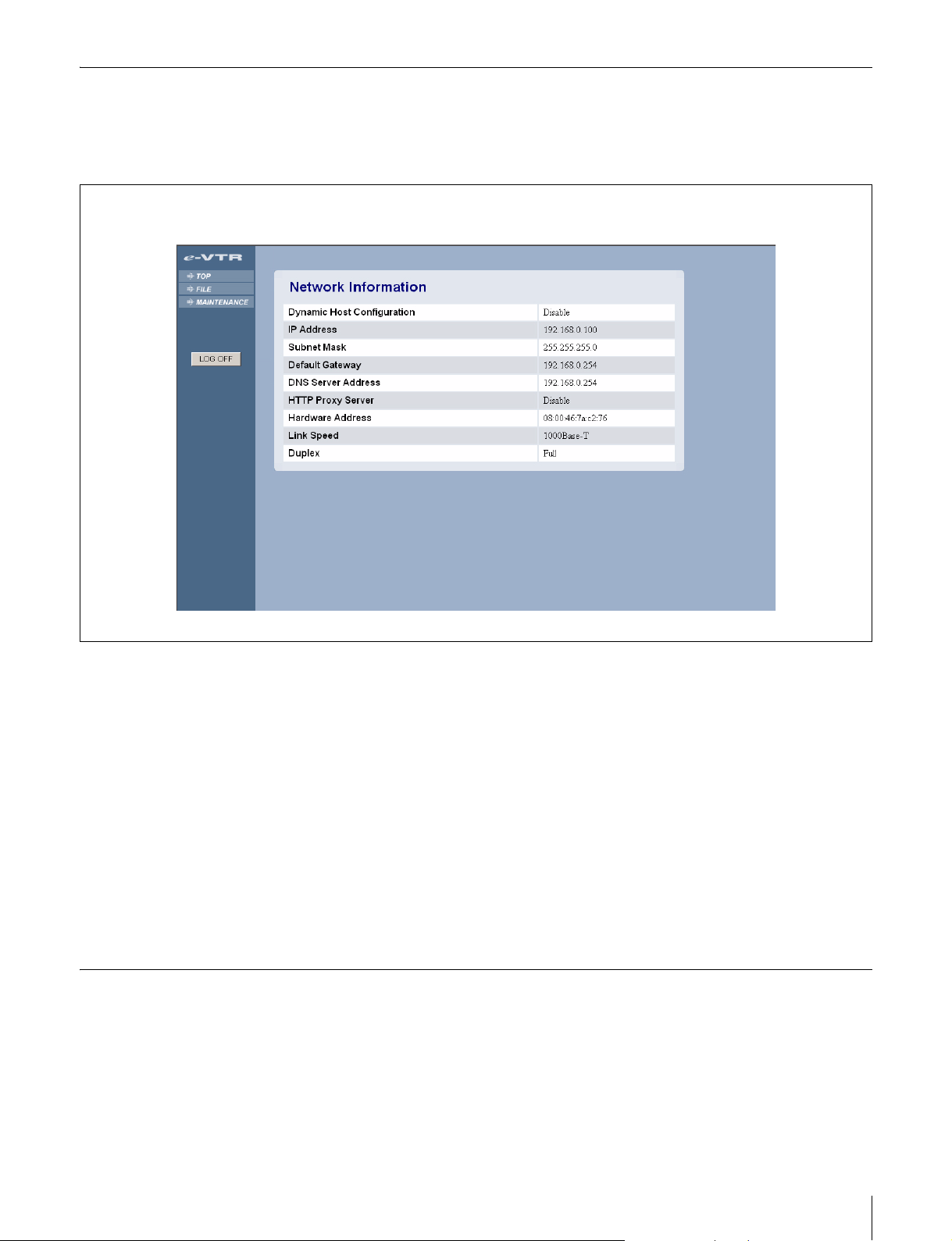
Network Information Page
The Network Information page shows the status of the
network to which the e-VTR is currently connected.
Dynamic Host Configuration
Indicates whether the mode enabling automatic IP address
acquisition is being used or not.
IP Address
Displays the IP address.
Subnet Mask
Displays the subnet mask.
Default Gateway
Displays the IP address of the default gateway.
DNS Server Address
Displays the address of the DNS server.
MENU Information for Network Page
The MENU Information for Network page displays the
settings of 8 menu items of the e-VTR. (No setting is made
on this page.)
For details on the menu items, refer to the Operation
Manual or Maintenance Manual of the e-VTR.
HTTP Proxy Server
Displays the internet proxy on/off when sending files to the
HTTP server.
Hardware Address
Displays the hardware address of the network board of the
e-VTR.
Link Speed
Displays the transmission speed of the network to which
the e-VTR is currently connected.
Duplex
Displays the connection status of the network: Full (full
duplex) or Half (half duplex).
Maintenance Page Operations
45
Page 46

MXF D10 Transfer Destination Page
Settings for MXF D10 file transfer through the operation
on the control panel of the e-VTR can be done on this page.
Up to 5 settings containing the following 5 items can be
registered.
Protocol
Select the transfer protocol.
Hostname/IPAdrs
Enter the hostname or IP address of the transfer destination
server.
User Name
Enter the user name to log in the transfer destination server.
Password
Enter the password to log in the transfer destination server.
Enter the same password in the Verify Password fiield.
Path
Specify the directory path to the storage location in the
destination server.
When specifying the path, enter / (slash) at the end.
Maintenance Page Operations
46
Page 47

MXF Proxy AV Transfer Destination Page
Settings for the MXF Proxy AV file transfer through the
operation on the control panel of the e-VTR can be done
on this page. Up to 5 settings containing the following 5
items can be registered.
Protocol
Select the transfer protocol.
Hostname/IPAdrs
Enter the hostname or IP address of the transfer destination
server.
User Name
Enter the user name to log in the transfer destination server.
Password
Enter the password to log in the transfer destination server.
Enter the same password in the Verify Password fiield.
Path
Specify the directory path to the storage location in the
destination server.
When specifying the path, enter / (slash) at the end.
Maintenance Page Operations
47
Page 48

DNS Server & HTTP Proxy Server Page
Settings of the DNS (Domain Name System) server and
internet proxy can be done on this page.
Setting the DNS server
To automatically acquire the DNS server from the DHCP
server, select the Dynamic Configuration option.
To specify a certain IP address, select the Designate
Address as follows option, and enter the IP address in the
Address field.
Note
To automatically acquire the DNS server from the DHCP
server, the IP address and subnet mask must be
automatically acquired at the same time. It is not possible
to acquire the DNS server setting alone from the DHCP
server. When you do not use the DNS server and specify
an destination server by directly entering the IP address,
these settings are not required.
Setting the HTTP Proxy Server
To send files to the HTTP server via the proxy server,
specify the network address and port number of the proxy
server. These settings are not required when you do not
use the proxy server.
Maintenance Page Operations
48
Page 49

The material contained in this manual consists of information
that is the property of Sony Corporation and is intended solely
for use by the purchasers of the equipment described in this
manual.
Sony Corporation expressly prohibits the duplication of any
portion of this manual or the use thereof for any purpose other
than the operation or maintenance of the equipment described
in this manual without the express written permission of Sony
Corporation.
Page 50

BKMW-E3000 (SYM)
3-857-242-01 (1)
Sony Corporation
B & P Company
© 2004
 Loading...