

SONY BA 06 Service Manual

OKI B6100
Laser Printer
Base Engine Technical Manual
Version 1.0

NOTICE
The information in this manual is subject to change without notice.
Every effort has been made to ensure that the information in this document is complete, accu-
rate, and up-to-date. The manufacturer assumes no responsibility for the results of errors
beyond its control.
While all reasonable efforts have been made to make this document as accurate and helpful as
possible, we make no warranty of any kind, expressed or implied, as to the accuracy or completeness of the information contained herein.
Copyright © 2003 Oki Data Americas, Inc. All rights reserved.

FEDERAL COMMUNICATIONS COMMISSION NOTICE
This equipment has been tested and found to comply with the limits for a Class B digital device,
pursuant to Part 15 of the FCC Rules. These limits are designed to provide reasonable protection against harmful interference in a commercial installation. This equipment generates, uses,
and can radiate radio frequency energy and, if not installed and used in accordance with the
instruction, may cause harmful interference to radio communications. However there is no guarantee that interference will not occur in a particular installation. If this equipment does cause
harmful interference to radio or television reception, which can be determined by turning the
equipment off and on, the user is encouraged to try to correct the interference by one or more of
the following measures:
• Re–orient or relocate the receiving antenna
• Increase the separation between the equipment and receiver
• Connect the equipment into an outlet on a circuit different from that to which the receiver is
connected
• Consult the dealer or an experienced radio/television technician for help.
The user may find the following booklet prepared by the Federal
Communications Commission helpful:
“How to Identify and Resolve Radio-TV Interference Problems”. This booklet is available from
the U.S. Government Printing Office, Washington D.C. 20402, Stock No. 004-000-00345-4.
Modifications
Changes or modifications to this equipment not expressly approved
by Xerox International Partners may void the user's right to
operate the equipment.

CANADIAN NOTICE
This digital apparatus does not exceed the Class B limits for radio noise emissions from digital
apparatus set out in the Radio interference regulations of the Canadian Department of Communications.
AVIS CANADIEN
Cet appareil numerique est conforme aux limites émission de bruits radioélectriques pour les
appareils de classe B stipulés das le réglement sur le brouillage radioéletrique du Ministére des
Communcations du Canada.
EUROPEAN NOTICE
This equipment has been tested and determined to be compliant with VDE requirements for a
Class B device.
HINWEIS
Hiermit wird bescheinigt, dass der Asama Laserdrucker, in bereinstimmung mit den Betimmun-
ngen der Vfg 104ß
Der Deutschen Bundespost wurde das Inverkehrbringen dieses Gertëes angqeigt und die Bere-
chtigung zur berprufung der Serie auf Einhaltung der Bestimmungen eingeräumt.
XEROX INTERNATIONAL PARTNERS
984 funkenstört ist.

CLASS 1 LASER PRODUCT
This Laser Printer is certified to comply with laser product performance standards set by the
U.S. Department of Health and Human Services as a Class 1 laser product. This means that this
is a class of laser product that does not emit hazardous laser radiation; this is possible only
because the laser beam is totally enclosed during all modes of customer operation.
The laser and output of the laser scanning unit produces a beam that, if looked into, could
cause eye damage. Service procedures must be followed exactly a written without change.
When servicing the machine or laser module, follow the procedures specified in the manual and
there will be no hazards from the laser.
Use of Controls, adjustments, or performance of procedures other than those specified herein
may result in a hazardous radiation exposure.
Unpacking the Base Engine
Be sure to carry the Base Engine by two or more persons taking care to hold it horizontally.
Be sure to take great care for persons not to hurt when carrying it.
Open the package and check the Base Engine for damage in transit.
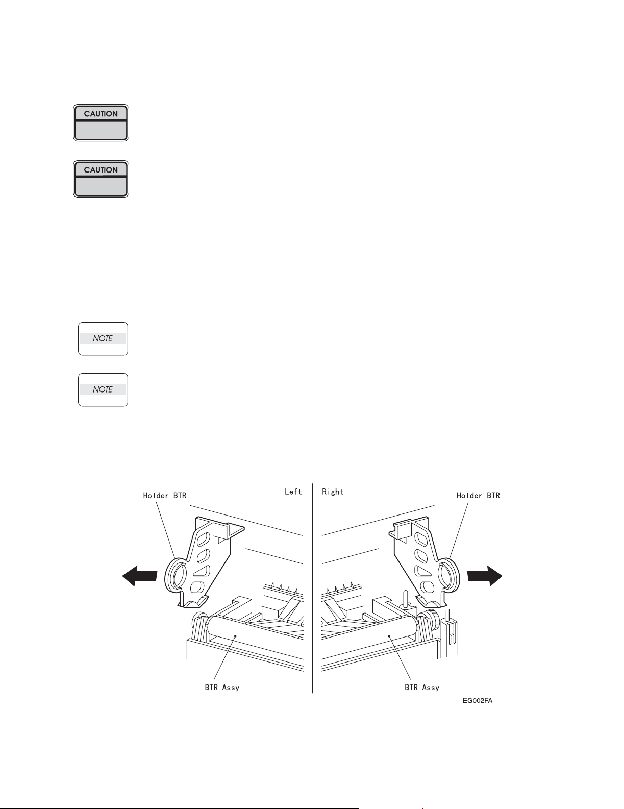
Remove the Holder BTR from the Base Machine after unpacking procedure of Base Engine.
Removal procedure of the Holder BTR is as follows.
1. Open the
2. Catch in the handle of the Holder BTR:L.And pull out the Holder BTR:L from the Base Machine to your
side with diagonal and upper direction.
3. Catch in the handle of the Holder BTR:R.And pull out the Holder BTR:R from the Base Machine to your
side with diagonal and upper direction.
Cover Assy Front
Take care not to give a damage to the Roll surface of the Roll Assy BTR when do the
following procedure.
Holding the Base Machine when do the following procedure.
(PL1.1.9).

Contents
Introduction . . . . . . . . . . . . . . . . . . . . . . . . . . . . . . . . . . . . . . . . . . . . . . . . . . . . . . . . . . . . . . . ix
About this Manual . . . . . . . . . . . . . . . . . . . . . . . . . . . . . . . . . . . . . . . . . . . . . . . . . . . . . . . . . .x
Safety Information . . . . . . . . . . . . . . . . . . . . . . . . . . . . . . . . . . . . . . . . . . . . . . . . . . . . . . . . xi
Service Section
1. The Service Flowchart . . . . . . . . . . . . . . . . . . . . . . . . . . . . . . . . . . . . . . . . . . . . 7
2. The Fault Isolation Procedure (FIP) Flowchart . . . . . . . . . . . . . . . . . . . . 2-1
3. Primary FIPs: Error Codes . . . . . . . . . . . . . . . . . . . . . . . . . . . . . . . . . . . . . . . 3-1
4. Primary FIPs: Printer Performance Problems . . . . . . . . . . . . . . . . . . . . . 4-1
5. Primary FIPs: Image Quality Problems . . . . . . . . . . . . . . . . . . . . . . . . . . . 5-1
6. Secondary FIPs . . . . . . . . . . . . . . . . . . . . . . . . . . . . . . . . . . . . . . . . . . . . . . . . . . 6-1
7. Diagnostic Tool and Test Pattern Mode . . . . . . . . . . . . . . . . . . . . . . . . . . . 7-1
8. Diagnostic Mode . . . . . . . . . . . . . . . . . . . . . . . . . . . . . . . . . . . . . . . . . . . . . . . . . 8-1
9. Adjustment Mode . . . . . . . . . . . . . . . . . . . . . . . . . . . . . . . . . . . . . . . . . . . . . . . . 9-1
10. Removal and Replacement Procedures . . . . . . . . . . . . . . . . . . . . . . . . . . 10-1
11. Locating P/J Connectors . . . . . . . . . . . . . . . . . . . . . . . . . . . . . . . . . . . . . . . . 11-1
12. Parts List . . . . . . . . . . . . . . . . . . . . . . . . . . . . . . . . . . . . . . . . . . . . . . . . . . . . . . . 12-1
Technical Reference Section
13. Principles of Operation . . . . . . . . . . . . . . . . . . . . . . . . . . . . . . . . . . . . . . . . . 13-1
14. Wiring Diagrams and Signal Information . . . . . . . . . . . . . . . . . . . . . . . . 14-1
15. Printer Specifications . . . . . . . . . . . . . . . . . . . . . . . . . . . . . . . . . . . . . . . . . . . 15-1
Optional Equipment Technical Manuals
Option Feeder . . . . . . . . . . . . . . . . . . . . . . . . . . . . . . . . . . . . . . . . . . . . . . . . . . . . . TRAY-1
Envelope Feeder . . . . . . . . . . . . . . . . . . . . . . . . . . . . . . . . . . . . . . . . . . . . . . . . . . . ENV-1
Duplex . . . . . . . . . . . . . . . . . . . . . . . . . . . . . . . . . . . . . . . . . . . . . . . . . . . . . . . . . . . . . DUP-1
Offset Catch Tray. . . . . . . . . . . . . . . . . . . . . . . . . . . . . . . . . . . . . . . . . . . . . . . . . . . OCT-1
OKI B6100 Laser Printer - Base Engine Technical Manual vii
Version 1.0

Blank Page
viii OKI B6100 Laser Printer - Base Engine Technical Manual
Version 1.0

Introduction
This manual contains technical and service information for the OKI B6100 (page per minute) Laser Printer.
The information is based on and validated using the basic model printer. Expect some minor discrepancies
in physical appearance, hardware count, and electrical readings due to engineering modifications and
manufacturing changes during the life of the product.
The information in this manual is presented with the assumption that the OEM customer has designed their
PWB ESS (Controller) to implement service diagnostics exactly as described in the Video Interface Specifications and in this manual.
This manual serves as both a technical reference manual and as a guideline for OEM clients who wish to
prepare their own service manual. Other uses are prohibited.
This manual is prepared for use in the United States by Xerox International Partners, Technical Services
Group. This manual is copyrighted. No portion may be copied, reproduced, submitted to, or read by XIP
external customers without the prior consent of XIP.
OKI B6100 Laser Printer - Base Engine Technical Manual ix
Version 1.0
About this Manual
Symbols Used in This Manual
NOTE: A Note indicates an operating or maintenance procedure, practice, or condition that is necessary
to accomplish a task efficiently.
CAUTION: A Caution indicates an operating or maintenance procedure, practice, or condition
that, if not strictly observed, could result in damage to, or destruction of, equipment.
WARNING: A Warning indicates an operating or maintenance procedure, practice, or condi-
tion that, it not strictly observed, could result in injury or loss of life.
Additional documentation for OKI B6100
• User Manual
The manual that describes how to operate and maintain the OKI B6100 Laser Printer
• Performance Data
The FX internal OEM document that provides detailed OKI B6100 performance information
• Interface Specifications
The FX internal OEM document that provides detailed OKI B6100 video interface specification data
• Spare Parts List
The XIP internal document that provides part numbers for the OKI B6100 printer
x OKI B6100 Laser Printer - Base Engine Technical Manual
Version 1.0

Safety information
Follow these safety instructions to prevent accidents while servicing the OKI B6100 Laser Printer. Always
be aware of the potential dangers that are present when you are working with electrical or mechanical
equipment.
Power supply and electrical components
Before starting any service procedure, switch off the printer power and unplug the power cord from the wall
outlet. If you must service the printer with power applied, be aware of the potential for electrical shock.
WARNING: Do not touch any electrified component unless you are instructed to do so by a
service procedure
Mechanical components
Hand crank to inspect sprockets and gears. Do not try to hand crank the printer while the Motor Assy is
running.
OKI B6100 Laser Printer - Base Engine Technical Manual xi
Version 1.0

ROS Assy
WARNING: This printer uses a laser as part of the printing process. The laser beam is a very
powerful, straight, narrow beam of light that produces extreme heat at its focal
point. The laser beam in the Asama printer is invisible. Although you cannot see
the beam, it can still cause severe damage. Direct eye exposure to the laser beam
may cause eye injury or blindness.
To avoid permanent eye damage, follow these directions:
• Before starting any service procedure, switch off the printer power and unplug the power cord from
the wall outlet.
• Do not disassemble the ROS Assy or any laser component displaying a Laser Warning Sticker.
• Use caution when you are working around the ROS Assy or if you are performing laser related repair
procedures.
• The OKI B6100 Laser Printer is equipped with two safety switches; the Switch Assy I/L Front (the
switch that breaks the 24V circuit when the Cover Assy Front opens) and the Switch Assy I/L Rear
(the switch that breaks the 3.3V circuit for the Motor Assy Exit when the Cover Rear opens). The
Switch Assy I/L Front supplies the power to all internal components. The Switch Assy I/L Rear supplies the power to the Motor Assy Exit. It is extremely dangerous to cheat the Switch Assy I/L while
the CRU is removed.
Safety Components
Make sure fuses, interlock switches, covers and panels are all functioning properly after you have reinstalled or replaced them.
xii OKI B6100 Laser Printer - Base Engine Technical Manual
Version 1.0

Technical Services
Sections 1 The Service Flowchart
1. Service Flowchart . . . . . . . . . . . . . . . . . . . . . . . . . . . . . . . . . . . . . . . . . . . . . . . . . . . . . . . . 1-2
1.1 Identify the Problem. . . . . . . . . . . . . . . . . . . . . . . . . . . . . . . . . . . . . . . . . . . . . . . . . . . . . . 1-3
1.2 Clean the Printer. . . . . . . . . . . . . . . . . . . . . . . . . . . . . . . . . . . . . . . . . . . . . . . . . . . . . . . . . 1-3
1.3 Final Checkout . . . . . . . . . . . . . . . . . . . . . . . . . . . . . . . . . . . . . . . . . . . . . . . . . . . . . . . . . . 1-4
OKI B6100 Laser Printer - Base Engine Technical Manual 1-1
Version 1.0

Technical Services
1. Service Flowchart
First identify the following phenomena when any problems occur.
・ Occurrence of Error/Status Code
・ Problem of image quality
・ Problem of printer performance
Go to the section corresponding to the problem.
1-2 OKI B6100 Laser Printer - Base Engine Technical Manual
Version 1.0

Technical Services
1.1. Identify the Problem
1. Verify that the reported problem does exist.
2. Check for any error codes.
3. Execute three test prints.
4. Take note of any print quality problems in the three test prints.
5. Take note of any mechanical or electrical abnormalities that are present.
6. Take note of any unusual noise or smell coming from the printer.
7. When you have identified the problem, go to the next block that is listed in the Service Flowchart.
1.2. Clean the Printer
1. Switch OFF the printer power.
2. Disconnect the AC power cord from the wall outlet.
3. Disconnect the power cord from the printer.
4. Open the Cover Assy Front.
5. Remove the CRU.
Cover the CRU with a dark cloth and store it away from strong light.
6. Inspect for and remove any foreign matter such as paper clips, staples, scraps of paper, paper dust, or
toner from the interior of the printer.
7. Clean the interior with a lint–free cloth, dampened slightly with cold water.
8. Clean the rubber rollers with a lint-free cloth, dampened slightly with cold water. Use a clean, lint-free
cloth to dry the rollers.
CAUTION: Use only water to clean the interior of the printer. Do not use
chemical solvents or cleaners.
Do not use any type of oil or lubricant on printer parts.
Solvents, cleaners, and oils may damage printer components.
9. Clean the Laser Scanner window with a soft, dry, lint-free cloth.
10. Use canned air to clean the BTR.
Do not touch the BTR with your fingers.
Do not clean the BTR with a brush or a damp cloth.
11. While cleaning, inspect the interior of the printer for damaged wires, loose connections, toner leakage,
and worn or damaged part.
12. If the CRU appears excessively dirty or obviously damaged, replace it with a new one.
13. When you have finished cleaning the printer, go to the next block that is listed in the Service Flowchart.
OKI B6100 Laser Printer - Base Engine Technical Manual 1-3
Version 1.0

Technical Services
1.3. Final Checkout
1. Reinstall all of the covers that you removed while servicing the printer.
2. Check that the original error code is gone and there are no new error codes displayed.
3. Execute a series of test prints.
The printer generates the test prints without jamming and without any print image defects.
4. Take note of any mechanical or electrical abnormalities that are present.
The printer runs through the entire print cycle without any obvious problems.
5. Take note of any unusual noise or smell coming from the printer.
During the print cycle there are no unusual noises or smells coming from the printer.
6. The call is completed.
Clean up your work area, and return the printer to the customer.
1-4 OKI B6100 Laser Printer - Base Engine Technical Manual
Version 1.0

Fault Isolation Procedures
Section 2 The Fault Isolation Procedure (FIP) Flowchart Contents
2. The FIP Flowchart . . . . . . . . . . . . . . . . . . . . . . . . . . . . . . . . . . . . . . . . . . . . . . . . . . . . . . . . 2-2
General Notes on Using FIPs. . . . . . . . . . . . . . . . . . . . . . . . . . . . . . . . . . . . . . . . . . . . . . . 2-3
FIP Flowchart. . . . . . . . . . . . . . . . . . . . . . . . . . . . . . . . . . . . . . . . . . . . . . . . . . . . . . . . . . . . . . 2-4
OKI B6100 Laser Printer - Base Engine Technical Manual 2-1
Version 1.0

Fault Isolation Procedures
2. The FIP Flowchart
If you used the Service Flowchart, it should have directed you to this section. Now, follow the FIP Flowchart to analyze your printer problem.
How to Use the FIP Flowchart
1. If you have an error code displayed on the screen of the Diagnostic Tool; go to the ERROR CODE box.
2. If you have a printer operation problem; go to the PRINTER PERFORMANCE box.
3. If you have a print image problem; go to the IMAGE QUALITY box.
4. Follow the arrow leading from your problem box to the individual FIP (Fault Isolation Procedure) that
corresponds to your error code, printer operation problem, or print image problem.
5. Follow the instructions presented in the FIP.
How to Follow a FIP
1. Each numbered step in a FIP instructs you to perform a certain action or procedure.
2. The instruction is followed by a question.
3. If your response to the question is Yes, then follow the instructions for a Yes reply.
4. If your response to the question is No, then follow the instructions for a No reply.
5. FIPs often ask you to take voltage readings at certain test points within the printer. Appendices D and E contain information on signal names and test point locations.
6. FIPs often ask you to replace a printer component. Section 9 Removal/Replacement provides you detailed procedures for removing and replacing all
major parts of the Asama printer.
2-2 OKI B6100 Laser Printer - Base Engine Technical Manual
Version1.0

Fault Isolation Procedures
General Notes on Using FIPs
1. FIPs assume there is no malfunction in printer controller. If you are unable to fix a problem using the
FIPS, we recommend that you replace the printer controller.
2. FIPs use new and "known good" components as troubleshooting tools. We recommend you carry a
spare CRU, PWBA HKB MCU, and PWB ESS.
3. Unless indicated otherwise, the instruction "switch ON main power" means for you to switch ON printer
power, and let the printer proceed through power-on diagnostics and warm-up until it is on-line and
ready to print.
4. Conventions used to represent connectors:
P/J XX means a Plug and its corresponding Jack, are connected.
PXX means a Plug is disconnected. (Unless this plug is soldered to a PWB).
JXX means a Jack is disconnected. (Unless this jack is soldered to a PWB).
5. When you are instructed to take a voltage reading between "P/J A–B and P/J X–Y", place the red
probe (+) of your meter on pin B of P/J A, and place the black probe (–) of your meter on pin Y of P/J X.
6. When you are instructed to take voltage readings between "P/J X and P/J Y" (without specified pin
numbers), check all voltage carrying pins. Refer to the Wiring/Connection Diagrams for signals and pin
numbers.
7. When you are instructed to take a voltage reading, the black probe (–) is generally connected to a pin
that is either RTN (Return) or SG (Signal Ground). You can substitute any RTN pin or test point in the
printer, and you can use FG (Frame Ground) in place of any SG pin or test point.
8. Unless a FIP instructs you otherwise; before measuring voltages make sure the printer is switched ON,
the CRU and Cassette Assy are installed, and the Cover Assy Front and Cover Assy Rear are closed
(Interlock Switch is actuated).
9. All voltage values given in the FIPs are approximate values. Actual measured voltages may vary
somewhat from the given values.
10. FIPs may instruct you to remove or replace a component. Refer to Section 10 Removal and Replacement, for information on how to remove and reinstall a component.
11. When a FIP instructs you to replace a component, and that component is part of a larger assembly,
you should replace the entire assembly.
OKI B6100 Laser Printer - Base Engine Technical Manual 2-3
Version 1.0

Fault Isolation Procedures
FIP Flowchart
2-4 OKI B6100 Laser Printer - Base Engine Technical Manual
Version1.0

Primary FIPs:Error Codes
Section 3 Primary FIPs: Error Codes Contents
3. Primary FIPs: Error Codes . . . . . . . . . . . . . . . . . . . . . . . . . . . . . . . . . . . . . . . . . . . . 3-3
3.1 U1:MOTOR FAIL . . . . . . . . . . . . . . . . . . . . . . . . . . . . . . . . . . . . . . . . . . . . . . . . . . . . . . . . . . . . . 3-8
3.2 U2:ROS FAIL . . . . . . . . . . . . . . . . . . . . . . . . . . . . . . . . . . . . . . . . . . . . . . . . . . . . . . . . . . . . . . . . 3-9
3.3 U4:FUSER FAIL . . . . . . . . . . . . . . . . . . . . . . . . . . . . . . . . . . . . . . . . . . . . . . . . . . . . . . . . . . . . . 3-10
3.4 U5:FAN ASSY FAIL . . . . . . . . . . . . . . . . . . . . . . . . . . . . . . . . . . . . . . . . . . . . . . . . . . . . . . . . . . 3-12
3.5 U6:NVM FAIL . . . . . . . . . . . . . . . . . . . . . . . . . . . . . . . . . . . . . . . . . . . . . . . . . . . . . . . . . . . . . . . 3-13
3.6 E5:CLOSE TOP/REAR COVER . . . . . . . . . . . . . . . . . . . . . . . . . . . . . . . . . . . . . . . . . . . . . . . . . 3-14
3.7 E4-2:EXIT JAM. . . . . . . . . . . . . . . . . . . . . . . . . . . . . . . . . . . . . . . . . . . . . . . . . . . . . . . . . . . . . . 3-15
3.8 E4-3:EXIT JAM. . . . . . . . . . . . . . . . . . . . . . . . . . . . . . . . . . . . . . . . . . . . . . . . . . . . . . . . . . . . . . 3-18
3.9 E3-1:REG JAM . . . . . . . . . . . . . . . . . . . . . . . . . . . . . . . . . . . . . . . . . . . . . . . . . . . . . . . . . . . . . . 3-20
3.10 E3-2:REG JAM . . . . . . . . . . . . . . . . . . . . . . . . . . . . . . . . . . . . . . . . . . . . . . . . . . . . . . . . . . . . . 3-23
3.11 E2-0:EARLY FEED JAM . . . . . . . . . . . . . . . . . . . . . . . . . . . . . . . . . . . . . . . . . . . . . . . . . . . . . . 3-25
3.12 E2-1:MISFEED JAM . . . . . . . . . . . . . . . . . . . . . . . . . . . . . . . . . . . . . . . . . . . . . . . . . . . . . . . . . 3-27
3.13 C5:ADD PAPER TO TRAY 1/2/3 . . . . . . . . . . . . . . . . . . . . . . . . . . . . . . . . . . . . . . . . . . . . . . . 3-30
3.14 C5:ILLEGAL SIZE . . . . . . . . . . . . . . . . . . . . . . . . . . . . . . . . . . . . . . . . . . . . . . . . . . . . . . . . . . 3-31
3.15 C3:TRAY 1/2/3 OUT INSTALL TRAY . . . . . . . . . . . . . . . . . . . . . . . . . . . . . . . . . . . . . . . . . . . . 3-32
3.16 J5:LOW TONER NEED TO REPLACE PLEASE WAIT . . . . . . . . . . . . . . . . . . . . . . . . . . . . . . 3-33
3.17 J3:EP CARTRIDGE NOT IN POSITION. . . . . . . . . . . . . . . . . . . . . . . . . . . . . . . . . . . . . . . . . . 3-34
3.18 P1:FUSER PAUSE . . . . . . . . . . . . . . . . . . . . . . . . . . . . . . . . . . . . . . . . . . . . . . . . . . . . . . . . . . 3-35
3.19 PAPER SIZE ERROR. . . . . . . . . . . . . . . . . . . . . . . . . . . . . . . . . . . . . . . . . . . . . . . . . . . . . . . . 3-36
3.20 FUSER UNIT NEED TO REPLACE PLEASE WAIT . . . . . . . . . . . . . . . . . . . . . . . . . . . . . . . . 3-37
3.21 SERVICE ERRORS . . . . . . . . . . . . . . . . . . . . . . . . . . . . . . . . . . . . . . . . . . . . . . . . . . . . . . . . . 3-38
OKI B6100 Laser Printer - Base Engine Technical Manual 3-1
Version 1.0

Primary FIPs:Error Codes
3. Level 1 FIPs: Error Codes
The FIP Flowchart should have directed you to this section.
Before entering the Error Code FIPs, make sure:
1. Is the printer plugged into a recommended AC wall outlet?
2. Is the AC power provided at the wall outlet within recommended specifications?
3. Is the AC power cord connected to the printer.
4. Is the AC power cord in good condition; not frayed or broken?
5. Is the printer properly grounded through the AC wall outlet?
6. Is the printer located in an area where the temperature and humidity are moderate and stable?
7. Is the printer located in an area that is free of dust?
8. Is the printer located in an area away from water outlets, steamers, electric heaters, volatile gases, or
open flames?
9. Is the printer shielded from the direct rays of the sun?
10. Does the printer have recommended space around all sides for proper ventilation?
11. Is the printer sitting on a level and stable surface?
12. Is recommended paper stock being used in the printer?
13. Does the customer use the printer as instructed in the OKI B6100 User Manual?
14. Are consumables, such as the CRU, replaced at recommended intervals?
3-2 OKI B6100 Laser Printer - Base Engine Technical Manual
Version 1.0

Code
--
Message
Cause
Primary FIPs:Error Codes
OKI B6100 Error Codes
Results
-------------
How to Clear the Code
(If you cannot clear the code, go to
the appropriate error code FIP, or to
the option service manual)
U1
--
U1:MOTOR
FAIL
U2
--
U2:ROS FAIL
U4
--
U4:FUSER FAIL
There is a problem with the Motor Assy Main.
1. The rotation speed of the Motor Assy Main is
less than specified rpm and the state of a printer
does not turn READY, after the Motor Assy
Main started rotating 1.3 seconds passed.
2. The fail is detected during the Fan on operation.
There is a problem with the ROS Assy.
1. /BD signal intervals are longer than specified
value after ROS Motor start rotating.
2. After the interval of transmitting /BD signal
reaches the specified value, the interval is
longer than the specified value.
3. When the laser power does not reach the specified value.
There is a problem with the Fuser Assy.
1. Fuser Assy temperature is does not reach the
temperature even after 110 seconds passed.
2. Fuser Assy temperature gets lower than [Set
Temp. 125
°C], in printing.
3. Fuser Assy temperature gets higher than [Set
Temp. 220
°C].
Motor Assy Main, Laser Scanner,
and Fuser Assy controls stop at end
of print cycle.
-------------
Switch OFF Main Power.
Switch ON Main Power.
Motor Assy Main, Laser Scanner,
and Fuser Assy controls stop at end
of print cycle.
-------------
Switch OFF Main Power.
Switch ON Main Power.
Motor Assy Main, Laser Scanner,
and Fuser Assy controls stop at end
of print cycle.
-------------
Switch OFF Main Power.
Switch ON Main Power.
4. The thermistor disconnection is detected.
5. The heat lamp continuously turns on for 10 seconds during the Standby Mode.
U5
--
U5:Fan Assy
FAIL
There is a problem with the Fan Assy.
1. The Fan Motor stops rotating after the printer
power is turned on.
Motor Assy Main, Laser Scanner,
and Fuser Assy controls stop at end
of print cycle.
-------------
Switch OFF Main Power.
Switch ON Main Power.
U6
--
U6:NVM FAIL
There is a problem with NVRAM.
1. An NVRAM read error occurred immediately
when you switched ON main power.
2. A write error occurred when you tried to write to
NVRAM.
Motor Assy Main, Laser Scanner,
and Fuser Assy controls stop at end
of print cycle.
-------------
Switch OFF Main Power.
Switch ON Main Power.
3. The overflow of the Task Table.
OKI B6100 Laser Printer - Base Engine Technical Manual 3-3
Version 1.0

Primary FIPs:Error Codes
OKI B6100 Error Codes continued
Code
--
Message
Cause
Results
-------------
How to Clear the Code
(If you cannot clear the code, go to the
appropriate error code FIP, or to the
option service manual)
E5
--
CLOSE TOP /
REAR
COVER
E5
--
FACE UP TRY
OPEN
E4
--
E4-2:EXIT
JAM
E4
--
E4-3:EXIT
JAM
The Cover Assy Front and/or the Cover Rear are/
is open.
Motor Assy Main, Laser Scanner, and
Fuser Assy controls stop immediately.
-------------
Close the open cover.
The Cover Assy Rear Face Up is open. Motor Assy Main, Laser Scanner, and
Fuser Assy controls stop immediately.
-------------
Close the open cover.
There is a paper jam for the standard cut paper at
the Sensor Exit.
1. The Sensor Photo:Exit does not turn OFF
within the specified time after the Sensor Photo:
Exit turning ON.
2. The Sensor Photo:Exit turns ON immediately
Motor Assy Main, Laser Scanner, and
Fuser Assy controls stop immediately.
-------------
Open the Cover Assy Front or Rear.
Remove the jammed paper.
Close the Cover Assy Front or Rear.
after the power is turned on or when the Cover
Assy Front is close.
There is a paper jam at the Sensor Exit.
The paper of Universal or Custom does not actu-
ate the Sensor Photo:Exit within the specified time
from the Sensor Photo Regi OFF timing.
Motor Assy Main, Laser Scanner, and
Fuser Assy controls stop immediately.
-------------
Open the Cover Assy Front or Rear.
Remove the jammed paper.
Close the Cover Assy Front or Rear.
E3
--
E3-1:REG
JAM
There is a paper jam between the Sensor
Photo:Regi and the Sensor Exit in the Fuser Assy.
The paper does not actuate the Sensor Exit of the
Fuser Assy within the specified time after the Sensor Photo:Regi activated.
Motor Assy Main, Laser Scanner, and
Fuser Assy controls stop immediately.
-------------
Open the Cover Assy Front.
Remove the jammed paper.
Close the Cover Assy Front.
E3
--
E3-2:REG
JAM
There is a paper jam at the Regi position.
The Sensor Photo:Regi turns ON immediately
after the power is turned ON or when the Cover
Assy Front is close.
Motor Assy Main, Laser Scanner, and
Fuser Assy controls stop immediately.
-------------
Open the Cover Assy Front.
Remove the jammed paper.
Close the Cover Assy Front.
3-4 OKI B6100 Laser Printer - Base Engine Technical Manual
Version 1.0

Code
--
Message
Cause
Primary FIPs:Error Codes
OKI B6100 Error Codes continued
Results
-------------
How to Clear the Code
(If you cannot clear the code, go to the
appropriate error code FIP, or to the
option service manual)
E2
--
E2-0:EARLY-
FEED JAM
E2
--
E2-1:MIS-
FEED JAM
C5
--
C5:ADD
PAP ER TO
TRAY1/2/3
C5
--
C5:ILLEGAL
SIZE
There is a paper jam at the Sensor Photo:Regi.
The paper actuates the Sensor Photo:Regi too
early.
There is a paper jam at the Sensor Photo:Regi.
The paper does not reach the Sensor Photo:Regi
within the specified time.
Tray 1/2/3 is out of paper.
The Sensor Photo:No Pap1/2/3 on the PWBA
Feeder (PL3.1.36) is actuated.
The paper fed from the Tray 1/2/3 is different from
the NVM set size.
Motor Assy Main, Laser Scanner, and
Fuser Assy controls stop immediately.
-------------
Open the Cover Assy Front.
Remove the jammed paper.
Close the Cover Assy Front.
Motor Assy Main, Laser Scanner, and
Fuser Assy controls stop immediately.
-------------
Open the Cover Assy Front.
Remove the jammed paper.
Close the Cover Assy Front.
The printer completes only the current
print cycle.
-------------
ADD the paper to the Tray 1/2/3.
The printer completes only the current
print cycle.
-------------
Replace the stacked paper and reload
the correct size paper.
C3
--
C3:TRAY1
OUT INSTALL
TRAY
Tray 1 is not installed or installed not in the position.
Motor Assy Main, Laser Scanner, and
Fuser Assy controls stop immediately.
-------------
Reinstall Tray 1 completely.
OKI B6100 Laser Printer - Base Engine Technical Manual 3-5
Version 1.0

Primary FIPs:Error Codes
OKI B6100 Error Codes continued
Code
--
Message
Cause
Results
-------------
How to Clear the Code
(If you cannot clear the code, go to the
appropriate error code FIP, or to the
option service manual)
J5
--
J5:LOW
TONER NEED
TO REPLACE
PLEASE
WAIT
J5
--
J5:LOW
TONER NEED
TO REPLACE
READY TO
PRINT
J3
--
EP
CARTRIDGE
NOT IN POSI-
TION
P1
--
FUSER
PAUSE
The CRU is nearing end of life and needs to be
replaced soon.
Displays warning message.
-------------
Replace the CRU.
The CRU is nearing end of life and needs to be
replaced soon.
Displays warning message.
-------------
Replace the CRU.
The CRU is not installed or installed not in the
position.
Motor Assy Main, Laser Scanner, and
Fuser Assy controls stop immediately.
-------------
Reinstall the CRU, or install a new
CRU.
The printer received a SET PAUSE command. The ROS Motor and the Fuser Assy
controls stop after printing is completed.
-------------
Turn the Main Power OFF and ON.
--
PAPER SIZE
ERROR
The size of the paper loaded in the cassette is different than paper size that is stored in NVRAM.
In Duplex mode: The size of the paper loaded in
the cassette is not supported in Duplex Mode.
The printer completes the current print
cycle.
-------------
Rewrite the NVRAM using ADJUSTMENT MODE MENU.
3-6 OKI B6100 Laser Printer - Base Engine Technical Manual
Version 1.0

Code
--
Message
Cause
Primary FIPs:Error Codes
OKI B6100 Error Codes continued
Results
-------------
How to Clear the Code
(If you cannot clear the code, go to the
appropriate error code FIP, or to the
option service manual)
--
FUSER UNIT
NEED TO
REPLACE
PLEASE
WAIT
--
FUSER UNIT
NEED TO
REPLACE
READY TO
PRINT
The Fuser Assy is nearing end of life and better to
be replaced soon.
The Fuser Assy is nearing end of life and better to
be replaced soon.
Displays warning message.
-------------
Replace the Fuser Assy.
Displays warning message.
-------------
Replace the Fuser Assy.
OKI B6100 Laser Printer - Base Engine Technical Manual 3-7
Version 1.0

Primary FIPs:Error Codes
3.1 U1:MOTOR FAIL
There is a problem with the Motor Assy Main.
Step Actions and Questions Yes No
1
2
3
INITIAL ANALYSIS
Inspect the following components.
• Motor Assy Main (PL8.1.14)
• PWBA HKB26 MCU (PL10.1.13)
• Gear Assy Drive (PL8.1.13)
• PWBA HKB PS (PL10.1.17)
Are they compatible with your printer version, correctly
installed, not damaged, deformed, or contaminated?
MOTOR ASSY MAIN ANALYSIS
Use MAIN MOTOR TEST to check the Motor Assy Main
(PL8.1.14).
Does the Motor Assy Main run?
MOTOR ASSY MAIN (PL8.1.14) ANALYSIS
1. Remove the Motor Assy Main from the Gear Assy Drive
(PL8.1.13). Do not unplug the Motor Assy Main from the
PWBA HKB26 MCU (PL10.1.13).
2. Use MAIN MOTOR TEST to check the Motor Assy Main.
Does the Motor Assy Main run?
Go to step 2. Replace the
problem components.
Replace the
PWBA HKB26
MCU
(RRP10.1.7).
Replace the
Gear Assy
Drive
(RRP8.1.3).
Go to step 3.
Go to step 4.
4
5
6
3-8 OKI B6100 Laser Printer - Base Engine Technical Manual
MOTOR ASSY MAIN (PL8.1.14) ANALYSIS
Check the voltage between P/J291-9 <=> P/J291-6, P/J291-8
<=> P/J291-5 and P/J291-7 <=> P/J291-4.
Is there +24VDC between P/J291-9 <=> P/J291-6, P/J291-8
<=> P/J291-5 and P/J291-7 <=> P/J291-4 on the Motor Assy
Main?
PWBA HKB26 MCU (PL10.1.13) ANALYSIS
Check the voltage between P/J29-1 <=> P/J29-4, P/J29-2 <=>
P/J29-5 and P/J29-3 <=> P/J29-6.
Is there +24VDC between P/J29-1 <=> P/J29-4, P/J29-2 <=>
P/J29-5 and P/J29-3 <=> P/J29-6 on the PWBA HKB26
MCU?
PWBA HKB PS (PL10.1.17) ANALYSIS
Check the voltage between P/J281-1 <=> P/J281-4, P/J281-2
<=> P/J281-5 and P/J281-3 <=> P/J281-6 on the PWBA LVPS
Is there +24VDC between the each P/J281-1 <=> P/J281-4,
P/J281-2 <=> P/J281-5 and P/J281-3 <=> P/J281-6 on the
PWBA HKB26 MCU?
Replace the
Motor Assy
Main
(RRP8.1.7).
Replace the
PWBA HKB26
MCU
(RRP10.1.7).
Replace the
PWBA HKB26
MCU
(RRP10.1.7).
Go to step 5.
Go to step 6.
Replace the
PWBA HKB
PS
(RRP10.1.7).
Version 1.0

Primary FIPs:Error Codes
3.2 U2:ROS FAIL
There is a problem with the ROS Assy.
Step Actions and Questions Yes No
1
2
3
INITIAL ANALYSIS
Inspect the following components.
• ROS Assy (PL8.1.9)
• PWBA HKB26 MCU (PL10.1.13)
• PWBA HKB PS (PL10.1.17)
• CRU (PL8.1.1)
• Harness Assy ROS (J21-J211, J212, J213) (PL8.1.7)
• Harness Assy VDO (J22-J233) (PL8.1.8)
Are they compatible with your printer version, correctly
installed, not damaged, deformed, or contaminated?
NVRAM ANALYSIS
Check the parameter using ADJUSTMENT MODE MENU.
Is the parameters set correctly?
ROS MOTOR ANALYSIS
1. Check the ROS Motor using ROS MOTOR TEST.
2. If you cannot hear the ROS Motor running, unplug P/J29
(Motor Assy Main).
Can you hear the ROS Motor running before the U2 code
appears?
Go to step 2. Replace the
problem components.
Go to step 3. Set correct
paramete.r
Go to step 4. Go to 6.3
ROS Assy
Failure.
4
OKI B6100 Laser Printer - Base Engine Technical Manual 3-9
Version 1.0
LD DIODE ANALYSIS
1. Disconnect P/J22 and P/J21 on the PWBA HKB26 MCU
(PL8.1.13).
2. Close the Cover Assy Front (PL1.1.9).
3. Switch ON Main Power.
4. Check the voltage between P21-5 and P21-6.
Is there +5 VDC between P21-5 and P21-6?
Go to 6.3
ROS Assy
Failure.
Go to 6.1
PWBA HKB
PS Failure
(+3.3 VDC).

Primary FIPs:Error Codes
3.3 U4:FUSER FAIL
There is a problem with the Fuser Assy.
Step Actions and Questions Yes No
1
2
INITIAL ANALYSIS
Inspect the following components.
• Fuser Assy (PL6.1.7)
• Harness Assy Fuser-M (J271, J11, J27, J262) (PL6.1.12)
• PWBA HKB26 MCU (PL10.1.13)
• PWBA HKB PS (PL10.1.17)
• Switch Assy I/L Front (PL10.1.12)
• Switch Assy I/L Rear (PL10.1.7)
• Sensor Photo Exit in the Fuser Assy (PL6.1.7)
Are they compatible with your printer version, correctly
installed, not damaged, deformed, or contaminated?
SWITCH ASSY I/L FRONT (PL10.1.12) ANALYSIS
Check the Switch Assy I/L Front function using SENSOR/
SWITCH CHECH.
Does the Switch Assy I/L Front function correctly and
increment the Sensor Check number each time you actuate it?
Go to step 2. Replace the
problem components.
Go to step 3. Replace the
Switch Assy I/
L Front
(RRP10.1.12)
3
4
5
6
3-10 OKI B6100 Laser Printer - Base Engine Technical Manual
SWITCH ASSY I/L REAR (PL10.1.7) ANALYSIS
Check the Switch Assy I/L Rear function using SENSOR/
SWITCH CHECH.
Does the Switch Assy I/L Rear function correctly and
increment the Sensor Check number each time you actuate it?
HARNESS ASSY FUSER-M (J271, J11, J27, J262)
(PL6.1.12) ANALYSIS
Is there continuity between J271 and J11?
HEATER ASSY ANALYSIS
Does U4 appear after POWER–ON?
(Answer YES if there is a momentary Fuser Assy Warm-Up
Sequence)
HEAT ROD ANALYSIS
Let the Heat Rod cool down.
Does the Heat Rod glow when power is switched ON?
Go to step 4. Replace the
Switch Assy I/
L Rear
(RRP10.1.5).
Go to step 5. Replace the
Harness Assy
Fuser-M
(J271, J11,
J27, J262)
(RRP6.1.4).
Go to 6.5
Temperature
Sensor Failure.
Go to step 6. Go to 6.4
Go to step 6.
Heat Rod
Failure.
Version 1.0
 Loading...