

Sony AV-DV75 User Manual [en, es, fr]

OPERATING INSTRUCTIONS
For assistance and information
MANUAL DE INSTRUCCIONES
En (English)
MODE D'EMPLOI
E (Español)
F (Français)
8Z-AFÎ2-903-11
990620BCK-Y-9
call toll free 1-800-BUY-AIWA
(United States and Puerto Rico)
WARNING
TO REDUCE THE RISK OF TIRE OR ELECTRIC SHOCK. DO NOT EXPOSE THIS APPLIANCE TO RAIN OR MOISTURE.
CAUTION
RISK OF ELECTRIC SHOCK
DO NOT OPEN
“CAUTION:TO REDUCE THE RISK OF
ELECTRIC SHOCK,
DO NOT REMOVE COVER (OR BACK).
NO USER-SERVICEABLE PARTS INSIDE.
REFER SERVICING TO QUALIFIED
SERVICE PERSONNEL.”
Cx|:l.inafion o* Giapliicdl Symool.i.
T-l!- illl'llnr'',: ’liiS.-l '.■■.llh ..M/.-.llLM'l tvirliol.
A -.Inn ar oqji .'ifci.: t'liinijlo is r'.arn&c lo
iJ=inReiiX.s 'ajIt-.'JI' '.■.lil'-i 'hr-' ijri.il jci s
c’K k'«ur.‘ t'i;-.i iiiriv Ij“ s j-'f na-n:
ni.ignlLrif- !j ¡.'vjiist.tj'ii .1 is'i o: ■ 1(1.1111shock to persons.
Ttie TXd:, 11s I.-II ,;m O'.mini—c
tii.anglo li. ir.'Tk-it -o i-.-i' T-e j=>:i tn the
ip|pSIÉ|||iii|j|Hii^BI!îpi5iî^
rifi r'ti-r'..':!.o iS'îr'. irio: ir'i-'r.ir.i.i'-'r-: C. t:K'
lil(-.iliiii; -1. .r-mi'.-invirc the .apphriLo
PRECAUTIONS
Read the Operating Instructions carefully and completely before
operating the unit. Be sure to keep the Operating Instructions
for future reference. All warnings and cautions in the Operating
Instructions and on the unit should be strictly followed, as well
as the safety suggestions below.
Installation
1 Water and moisture — Do not use this unit near water, such
as near a bathtub, washbowl, swimming pool, or the like.
2 Heat — Do not use this unit near heat sources, including
heating vents, stoves, or other appliances that generate heat.
It also should not be placed in temperatures less than 5°C
(41 °F) or higher than 35°C (95°F).
3 Mounting surface — Place the unit on a flat, even surface.
4 Ventilation — The unit should be situated with adequate
space around it so that proper heat ventilation is assured.
Allow 10 cm (4 in.) clearance from the rear and the top of the
unit, and 5 cm (2 in.) from each side.
- Do not place the unit on a bed, rug, or similar surface that
may block the ventilation openings.
- Do not install the unit in a bookcase, cabinet, or airtight
rack where ventilation may be impeded.
5 Objects and liquid entry — Take care that objects or liquids
do not get inside the unit through the ventilation openings.
6 Carts and stands — When placed or
mounted on a stand or cart, the unit
should be moved with care.
Quick stops, excessive force, and
uneven surfaces may cause the unit or
cart to overturn or fall.
7 Wall or ceiling mounting — The unit should not be mounted
on a wall or ceiling, unless specified in the Operating
Instructions.
Owner’s record
For your convenience, record the model number and serial
number (you will find them on the rear of your unit) in the space
provided below. Please refer to them when you contact your
Aiwa dealer in case of difficulty.
Model No. Serial No. (Lot No.)
AV-DV75
Electric Power
1 Power sources — Connect this unit only to power sources
specified in the Operating Instructions, and as marked on
the unit.
2 Polarization — As a safety feature, some units are equipped
with polarized AC power plugs which can only be inserted
one way into a power outlet. If it is difficult or impossible to
insert the AC power plug into an outlet, turn the plug over
and try again. If it is not still inserted easily into the outlet,
please call a qualified service technician to service or replace
the outlet. To avoid defeating the safety feature of the
polarized plug, do not force it into a power outlet.
3 AC power cord
- When disconnecting the AC power cord, puli it out by the
AC power plug. Do not pull the cord itself.
- Never handle the AC power plug with wet hands, as this
could result in fire or shock.
- Power cords should be firmly secured to avoid being
severely bent, pinched, or walked upon. Pay particular
attention to the cord from the unit to the power socket.
- Avoid overloading AC power plugs and extension cords
beyond their capacity, as this could result in fire or shock.
4 Extension cord — To help prevent electric shock, do not
use a polarized AC power plug with an extension cord,
receptacle, or other outlet unless the polarized plug can be
completely inserted to prevent exposure of the blades of the
plug.
5 When not in use — Unplug the AC power cord from the AC
power outlet if the unit will not be used for several months or
more. When the cord is plugged in, a small amount of current
continues to flow to the unit, even when the power is turned
off.
ENGLISH
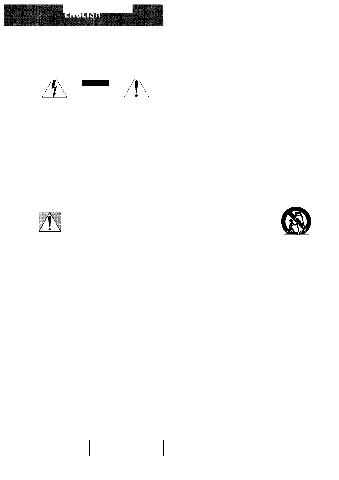
Outdoor Antenna
1 Power lines — When connecting an outdoor antenna, make
sure it is located away from power lines.
2 Outdoor antenna grounding — Be sure the antenna system
is properly grounded to provide protection against unexpected
voltage surges or static electricity build-up. Article 810 of the
National Electrical Code, ANSI/NFPA70, provides information
on proper grounding of the mast, supporting structure, and
the lead-in wire to the antenna discharge unit, as well as the
size of the grounding unit, connection to grounding terminals,
and requirements for grounding terminals themselves.
Antenna Grounding According to the National Electrical Code
TABLE OF CONTENTS
PRECAUTIONS
PREPARATIONS
CONNECTIONS.............................................................................3
BEFORE OPERATION.................................................................7
SOUND
______________________________________
CUSTOM AUDIO ADJUSTMENT
ELECTRONIC GRAPHIC EQUALIZER
DSP SURROUND........................................................................ 10
...
...........................................................................1
______________________________
...............................................
.....................................
8
9
Maintenance
Clean the unit only as recommended in the Operating
Instructions.
Damage Requiring Service
Have the unit serviced by a qualified service technician if:
- The AC power cord or plug has been damaged
- Foreign objects or liquid have gotten inside the unit
- The unit has been exposed to rain or water
- The unit does not seem to operate normally
- The unit exhibits a marked change in performance
- The unit has been dropped, or the cabinet has been damaged
DO NOT ATTEMPT TO SERVICE THE UNIT YOURSELF.
BASIC OPERATIONS
SELECTION OF AUDIO/VIDEO SOURCE
RECORDING AN AUDIO SOURCE
__________________________
..............................
........................................
.12
11
RADIO RECEPTION____________________________
MANUALTUNING
PRESETTING STATIONS.......................................................... 14
DOLBY SURROUND
SELECTING DOLBY SURROUND
ADJUSTING SPEAKER LEVEL BALANCE
ADJUSTING DOLBY DIGITAL SURROUND SOUND
......................................................................
___________________________
...........................................
..........................
............
13
IS
1£i
18
REMOTE CONTROL
OPERATING TV, CABLE TV, VCR AND CD PLAYER
TIMER
_______________________________________
SETTING THE CLOCK.......................................................... 2Cl
SETTING THE SLEEP TIMER
...............................................
..........
19
20
GENERAL____________________________________
SPECIFICATIONS...................................................................... 21
CARE AND MAINTENANCE.................................................. 22
TROUBLESHOOTING GUIDE
PARTS INDEX.......................................................................... 22
.................................................
22
APPENDIX
ID CODES FOR TV
ID CODES FOR CABLE TV.....................................................A-2
ID CODES FOR VCR................................................................ A-3
ID CODES FOR CD PLAYER
___________________________________
..................................................................
................................................
ENGLISH 2
A-1
A-4
'W
1
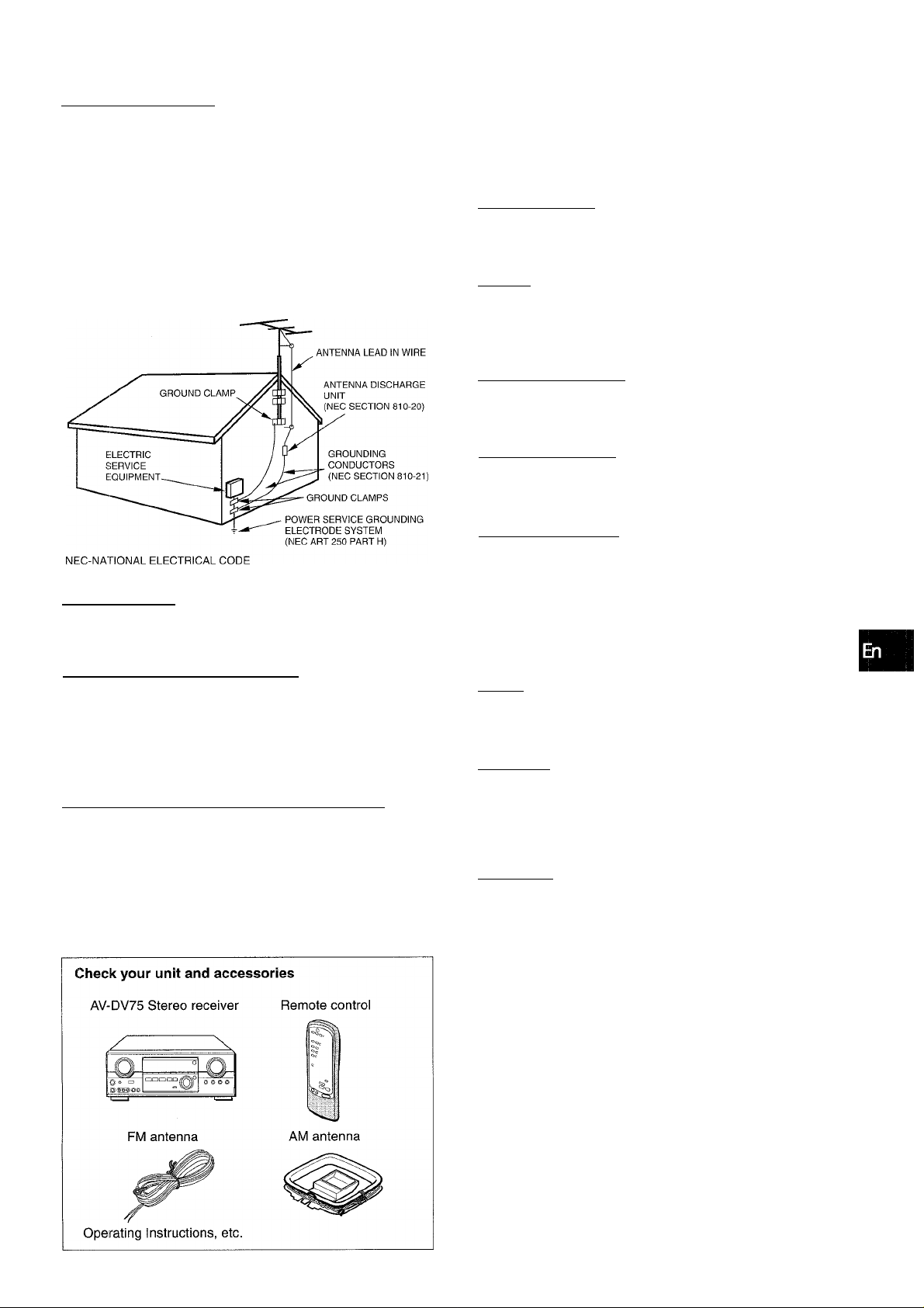
CONNECTIONS
Before connecting the AC cord
The rated voltage of your unit shown on the rear panel is 120 V
AC. Check that the rated voltage matches your local voltage.
IMPORTANT
Connect the speakers, antennas, and all other external
equipment first. Then connect the AC cord at the end.
*' Be sure to connect the VIDEO OUT terminal of a DVD player
directly to a TV set, not through this unit. Otherwise, the picture
noise may appear when playing copy protected DVDs.
Input sound through the DIGITAL IN terminals cannot be
recorded. When recording the sound from the DVD, CD, MD
or LD player, connect the analog AUDIO OUT terminals of the
player to the corresponding AUDIO IN terminals of the receiver.
When connecting a monaural video, use a stereo-mono
connecting cord (not supplied).
** When connecting an LD player equipped with the AC-3 RF
OUT terminal, use an RF demodulator unit. Also connect the
analog AUDIO OUT terminals of the LD player to the receiver
to play all the sources. For further information, refer to the
instructions of the LD player.
DVD or Video 1*^/MD player
CONNECTING EQUIPMENT
Jacks and plugs of the connecting cord are color-coded as
follows:
Red jacks and plugs: For the right channel of audio signals
White jacks and plugs: For the left channel of audio signals
Yellow jacks and plugs: For video signals
NOTE
Insert the plugs fully into the jacks. Loose connections may
produce a humming sound or other noise interference.
to OPTICAL
DIGITAL OUT
(DVD)
• Optical
connecting
cord
CD
to COAXIAL
DIGITAL OUT
RF demodulator*'’
Video 2*® or
LD*^/Cable TV
Coaxial
connecting
cord
Optical
connecting
cord
1 1
@ o
DVD or MD,CD Player
to AUDIO IN(Video l/MD)
to AUDIO OUT
to VIDEO OUT(Video 1)
to OPTICAL
DIGITAL OUT
FnF=fnFil
to AUDIO OUT
to VIDEO IN (Video 1)
WiiXiAi. fjy
IViDE0 2)
OPTICAL
ENGLISH
® and (D in the illustration correspond to the following details.
(Dam antenna (Dfm antenna
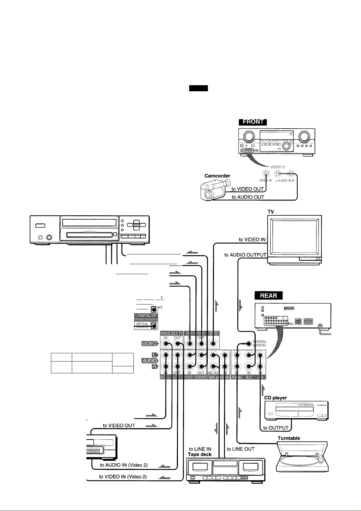
CONNECTING SPEAKERS®
Speaker terminals
Connect tront speakers (system A and/or B), a center speaker,
surround speakers and sub woofer to the corresponding speaker
terminals on the unit:
- the front speaker cords to the FRONT SPEAKERS terminals
- the center speaker cord to the CENTER SPEAKER terminals
- the surround speaker cords to the SURROUND SPEAKERS
terminals
- for more powerful bass, the sub woofer (with a built-in amplifier)
cord to the SUPER WOOFER 0 jack
When not connecting the sub woofer, be sure to select the
“SUBW OFF” (sub woofer off) mode (see page 7).
©Speaker system A ©Speaker system B
Front speakers
(/}
Z
o
2
UI
tr
a.
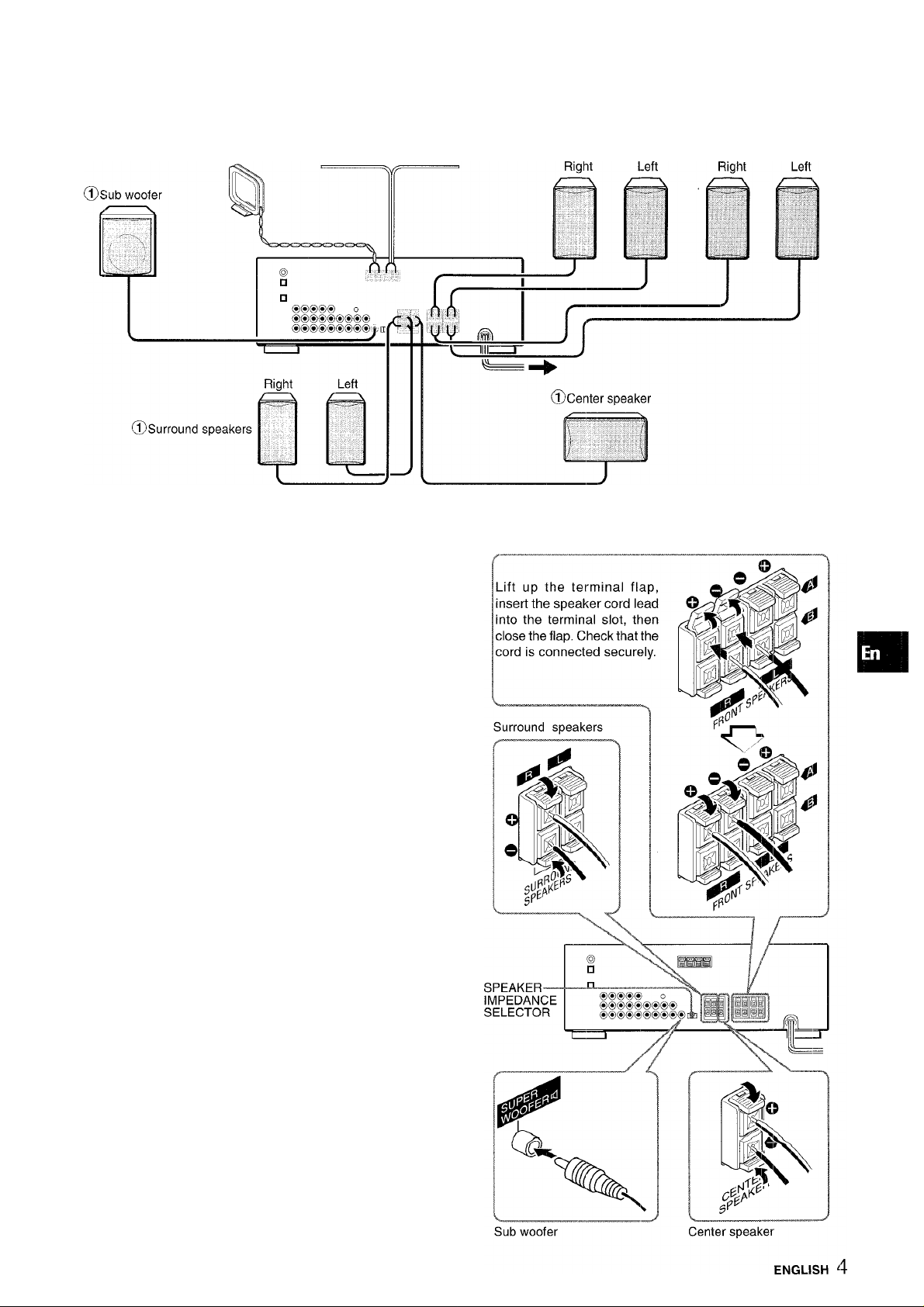
Speaker impedance
• Front and center speakers
Use the same impedance for both the front and center speakers.
The SPEAKER IMPEDANCE SELECTOR on the rear should be
set to the position that matches the impedance value of the front
and center speakers.
When using 4 ohm speakers, set the selector to IMP: 40. When
using 8 ohm speakers, set the selector to IMP: 80. Please unplug
the AC cord before setting the selector.
• Surround speakers and super woofer
The SPEAKER IMPEDANCE SELECTOR has no effect on the
SURROUND SPEAKERS terminals and the SUPER WOOFER
K1 jack. For the surround speakers and sub woofer, use speakers
of 8 ohms or more.
Connecting -h to +, - to - terminals
To get the proper sound effect, the speaker terminals on the unit
and the speaker should be connected with proper polarity; the +
terminal on the unit should be connected to the + terminal on
the speaker (and - to -).
• Be sure to connect the speaker cords correctly as shewn in
the illustration on the right column. Improper connections can
cause short circuits in the SPEAKER(S) terminals.
• Do not leave objects generating magnetism near the speakers.
•
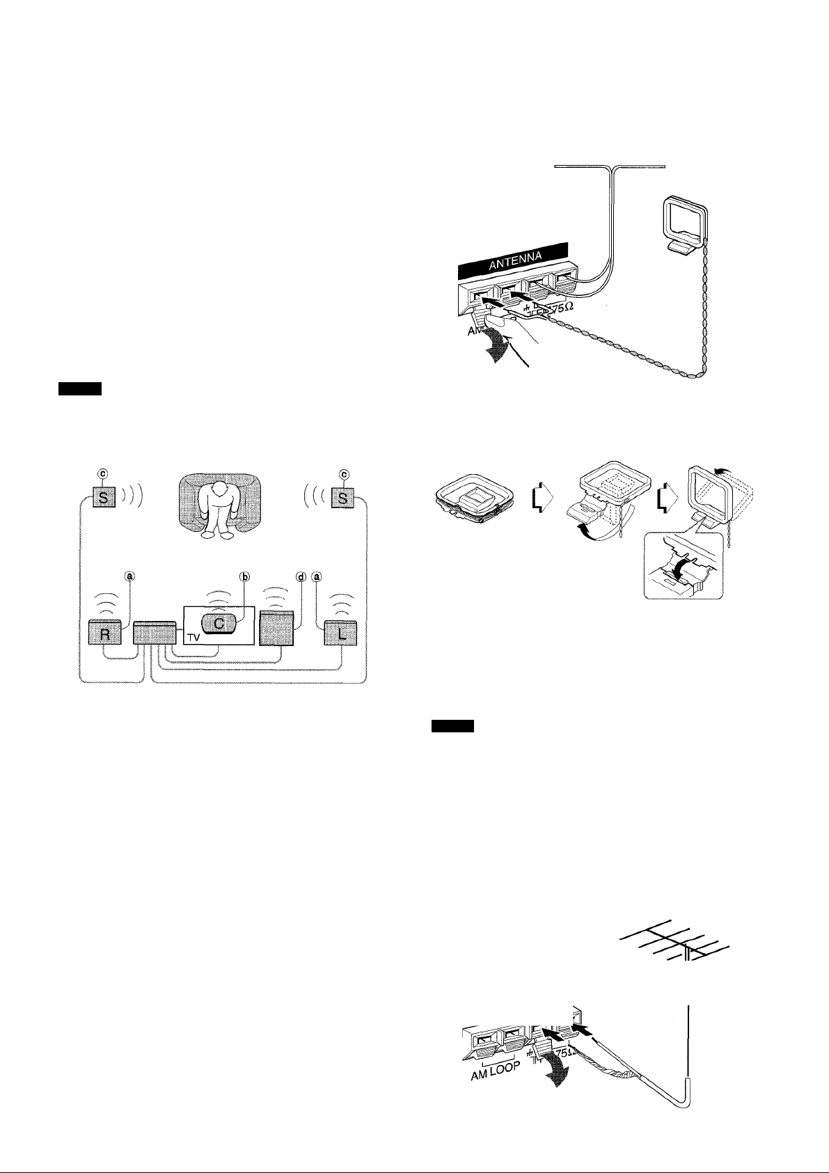
POSITIONING THE SPEAKERS
Position the speakers to make the most of the Dolby Digital
Surround, Dolby Pro Logic or DSP effect.
CONNECTING THE SUPPLIED ANTENNAS (D
Connect the FM antenna to the FM 750 terminals and the AM
antenna to the AM LOOP terminals.
d) Front speakers (B) Center speaker
Position in the center of the two front speakers, in addition,
position on or below the TV set, if connecting a TV set to the
unit.
© Surround speakers
Place the surround speakers directly to the side of or slightly
behind the listening area. Align them horizontally, about 1
meter (3.2 feet) above ear height.
@ Sub woofer
Place the sub woofer in any place between the two front
speakers.
When not connecting the sub woofer, be sure to select the
“SUBW OFF” (sub woofer off) mode (see page 7).
NOTE
Sound from the surround speakers or center speaker depends
on the setting of the DSP, Dolby Pro Logic and Dolby Digital
Surround.
FM antenna
AM antenna
To stand the AM loop antenna on a surface
Fix the claw to the slot as shown in the illustration.
To position the antennas FM feeder antenna:
Extend this antenna horizontally in a T shape and fix its ends to
the wall.
AM loop antenna:
Position for the best reception.
NOTE
• Do not bring the FM antenna near metal objects or curtain rails.
• Do not bring the AM antenna near other external equipment,
the unit itself, the AC power cord or speaker cords, as noise
will be picked up.
• Do not unwind the AM loop antenna wire.
CONNECTING AN OUTDOOR ANTENNA
For better FM reception, use of an outdoor antenna is
recommended. Connect the outdoor antenna to the FM 75Ì2
terminals.
ENGLISH
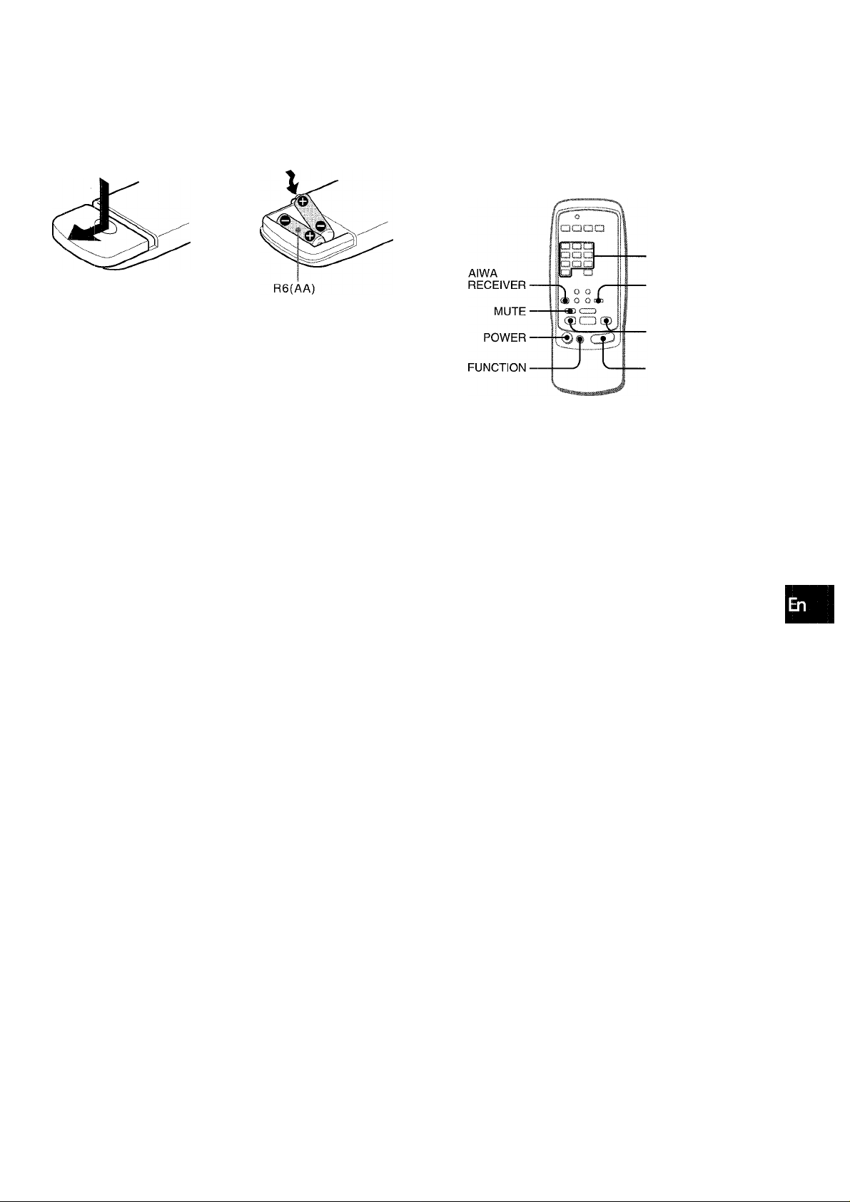
ABOUT THE REMOTE CONTROL
Inserting batteries
Detach the battery cover on the rear of the remote control and
insert two R6 (size AA) batteries.
c>
Remote control operation
This remote control system allows you to operate other external
equipment besides the AIWA receiver. For details of the remote
control operation for other external equipment, see “REMOTE
CONTROL" on page 19.
The following is an explanation on how to operate the Aiwa
receiver.
■ RECEIVER/DIGIT
■ SET UP
(/}
Z
o
g
;?
LU
tc
(Ì.
When to replace the batteries
The maximum operational distance between the remote control
and the sensor on the unit shouid be approximately 5 meters
(16 feet). When this distance decreases, replace the batteries
with new ones.
Using the remote control
The instructions in this manual refer mainly to the buttons on the
main unit, in principle buttons on the remote control with the
same names as those on the main unit can be used as weli.
• if the unit is not going to be used for an extended period of
time, remove the batteries to prevent possible electrolyte
leakage.
' The remote control may not operate correctly when:
- The line of sight between the remote control and the remote
sensor in the display window is exposed to intense light, such
as direct sunlight.
- Other remote controls are used nearby (those of a television,
etc.)
■ TUNER PRESET/
SURROUND
■VOLUME
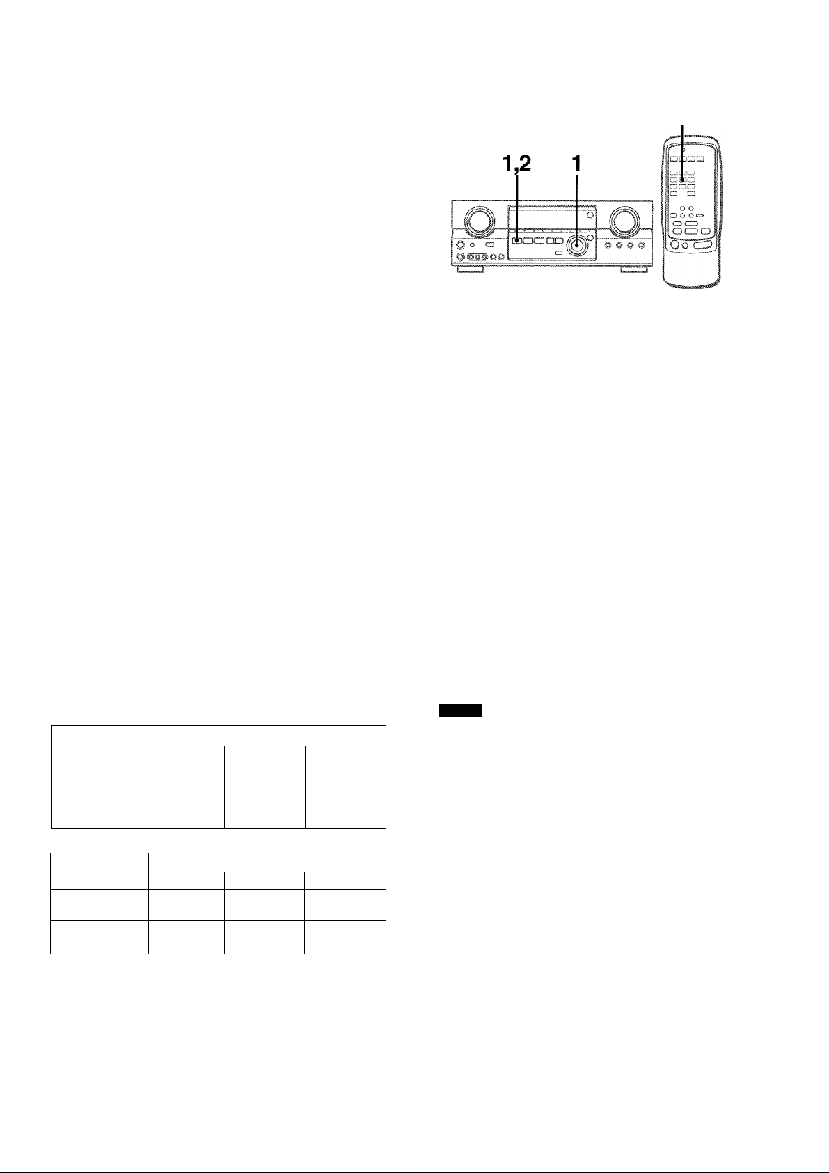
1 Press the AIWA RECEIVER button to set the
remote control to the Aiwa receiver mode.
2 Press one of the buttons indicated above.
FUNCTION button
Each time this button is pressed, the sound source changes
cyclically.
TUNER PRESET/SURROUND buttons
Tune in the station which has been preset on the receiver.
To go to a higher preset number, press the UP^W button. To
go to a lower preset number, press the DOWNM-^ button.
This button is also used when adjusting the speaker level
balance of the DSP, Dolby Pro Logic or Dolby Digital Surround
mode.
It is not necessary to press the AIWA RECEIVER button each
time you operate the Aiwa receiver unless another mode has
already been set. (See “REMOTE CONTROL” on page 19.)
If the receiver cannot be operated with the remote» controi
Follow the steps below using the remote control.
1 Press the AiWA RECEiVER button. 2 Press and hold the SET UP button for about 2.5
seconds.
The indicator on the top of the remote control blinks twice
while pressing the button.
3 Press the DIGIT buttons in the order of “4,” “0”
and “6.”
ENGLISH 6
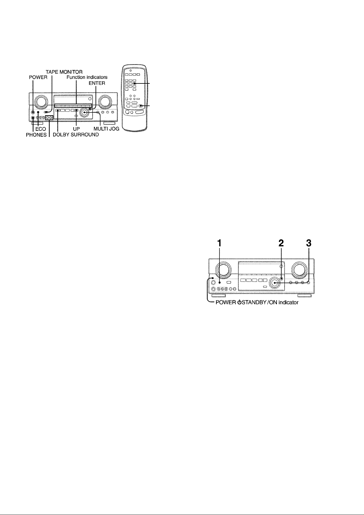
BEFORE OPERATION
MANUAL
SELECT
UP
FRONT SPEAKERS A,B
To turn the unit on
Press the POWER button.
Operation is possibie after four seconds. The VOL (volume) level
or function name is displayed one after the other for the first four
seconds.
The selected function indicator lights up in red and the others in
green.
To change the brightness ievel of the display
1 Press ECO so that “ECO MODE” is displayed.
2 Within 4 seconds, turn the MULTI JOG to display DIM MODE,
and then press the ENTER button within 4 seconds.
3 Within 4 seconds, turn the MULTI JOG to select the dimmer
mode as below.
The mode will be automatically set after 4 seconds. It will
also be set if the ENTER button is pressed within 4 seconds
after step 3.
■ DIM OFF ◄-►DIMMER 1-«-^ DIMMER 2 ◄-► DIMMER 3^
To select the front speaker system
To use speaker system A: Set the FRONT SPEAKERS A button
to -.ON.
To use speaker system B: Set the FRONT SPEAKERS B button
to -.ON.
To use both speaker systems: Set both the buttons to —.ON.
Set the button(s) to J.OFF to turn off the speaker system(s).
As the front speaker systems A and B are connected in series:
- The sound will decrease slightly when using both speaker
systems
- No sound can be heard if the FRONT SPEAKERS A and B
buttons are set to —.ON when only one speaker system is
connected
When not connecting a sub woofer
Be sure to select the “SUBW OFF” mode.
After pressing the DOLBY SURROUND button to turn on the
Dolby Pro Logic, press the MANUAL SELECT button on the
remote control once so that “SUBW ON” appears on the
display. Then press the UP button or turn the MULTI JOG
within four seconds to display “SUBW OFF.”
To turn the unit off, press the POWER button.
POWER ECONOMIZING (ECO) MODE
DIM-OFF: The normal display.
DIMMER 1: The illumination of the display is dimmer than
usual.
DIMMER 2: The illumination of the display is dimmer than
DIMMER 1.
DIMMER 3: The illumination of the display is dimmer than
DiMMER 2. The function indicators turn off.
Using the headphones
Connect headphones to the PFIONES jack with a standard stereo
plug (06.3 mm, 1/4 inch). Be sure to set the FRONT SPEAKERS
A and B buttons to JLOFF. Otherwise sound is output from the
speakers.
When the headphones are plugged in:
- The Dolby Pro Logic or DSP system is automatically canceled
-The Dolby Digital Surround mode is changed to the
“2chSTEREO (2CH DOWNMIX)” mode
Setting this unit to the ECO mode reduces power consumption
as below.
Initial setting of the ECO mode is ON.
• When the current time is set, the clock display disappears
immediately.
• While the power is off, all the display lights turn off, and only
the POWEROSTANDBY/ON indicator lights in red.
To cancei the ECO mode
1 Press the ECO button to display ECO MODE while the unit is
turned on.
2 Within 4 seconds, press the ENTER button.
3 Within 4 seconds, turn the MULTI JOG to select ECO OFF.
The mode will be automatically set after 4 seconds. It will
also be set if the ENTER button is pressed within 4 seconds
after step 3.
7 ENGLISH

CUSTOM AUDIO ADJUSTMENT
DOWN,UP VOLUME
MUTING
BALANCE T-BASS
•>1
BBE
- T-BASS
-BBE
-VOLUME
BBE SYSTEM
The BBE system enhances the clarity of high-frequency sound.
Press the BBE button.
Each time it is pressed, the level changes. Select one of th(3
three levels, or the off position to suit your preference.
T]
(cancel)
CO
'Z.
o
flQ
<o
£>. (0
LU
a
CL
VOLUME CONTROL
Turn the VOLUME control on the unit, or press the VOLUME
buttons on the remote control.
The volume level is shown on the display for four seconds. It can
be adjusted between 0 and MAX (31). It flashes when set over
the level of 21.
The volume level remains memorized even after the power is
turned off. However, if the power is turned off when the volume
is set to more than 17, it is automatically set to 16 the next time
the power is turned on.
To adjust the left/right balance of the front speakers
Press the BALANCE button to display ‘‘L/R OdB”. Then press
the DOWN or UP button repeatedly or turn the MULTI JOG within
four seconds.
Note that the front speaker balance for the Dolby Digital and
Dolby Pro Logic modes is also changed.
To mute the sound temporarily
Press the MUTING button (-20 dB).
“MUTE ON” appears on the display for four seconds. While muting
the sound, the selected function indicator flashes. Press the
MUTING button again to restore the sound.
’ The BBE system is automatically canceled;
- When the DIGITAL (Dolby Digital) mode is selected
- When the Dolby Pro Logic is turned on
' The BBE system cannot be turned on:
- While the DIGITAL (Dolby Digital) mode is selected
- While the Dolby Pro Logic is turned on
SUPER T-BASS SYSTEM
The T-BASS system enhances the realism of low-frequency
sound.
Press the T-BASS button.
Each time it is pressed, the level changes. Select one of the
three levels, or the off position to suit your preference.
I'.ill iie'.V.-:;:;:
C7
(cancel)
HBBB
Low-frequency sound may be distorted when the T-B ASS system
is used for a disc or tape in which low-frequency sound is
originally emphasized. In this case, cancel the T-BASS system.
SOUND ADJUSTMENT DURING RECORDING
The output volume and tone of the speakers or headphones may
be freely varied without affecting the level of the recording.
ENGLISH 8
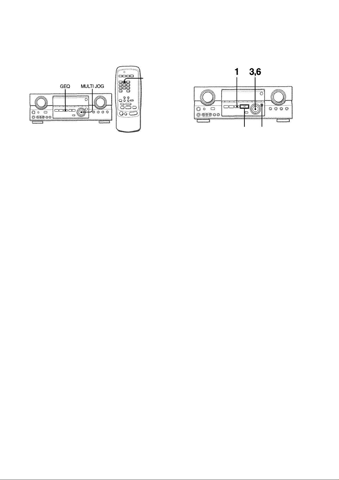
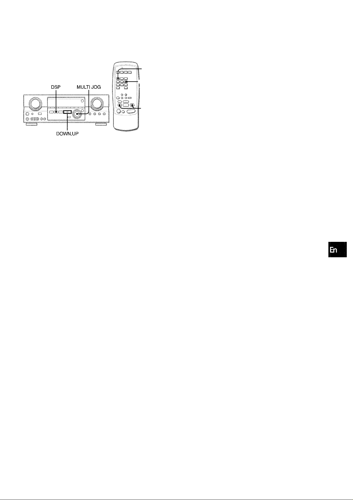
ELECTRONIC GRAPHIC EQUALIZER
SETTING NEW EQUALIZATION CURVES
Up to 4 equalization curves can be stored as the manual modes
Ml to M4.
■GEQ
2 1,5,7
This unit provides the following five different equalization modes.
ROCK: Powerful sound emphasizing treble and bass
POP: More presence in the vocals and midrange
JAZZ: Accented lower frequencies for jazz-type music
CLASSIC: Enriched sound with heavy bass and fine treble
BGM: Calm tone with suppressed bass and treble
Press the GEQ (Graphic Equalizer) button, and turn the MULTI JOG until the desired equalization mode is displayed.
The GEQ modes are displayed cyclically as follows.
M1
.
.....
-BGM-
.
ROCK-
The selected mode name is displayed for four seconds, and the
► indicator appears on the left side of the selected mode name.
POP-
M4 M3
JAZZ- CLASSIC
M2-
Manual mode
I : f -8 :
•'/ i'
A ■ ■ i*'.vl
f'iijCK
Selected mode
1 Press the GEQ button and press the ENTER
button within 4 seconds.
RocKirropir;
I
................
ii
2 Press the DOWN or UP button to seiect a
frequency.
The level indicator of the selected frequency flashes.
3 Turn the MULTI JOG to adjust the ievei of the
seiected frequency.
4 Repeat steps 2 and 3 to make the desired
equaiization curve.
In steps 2 and 3, the unit returns to normal mode when no
operation is made for about 8 seconds.
5 Within 8 seconds, press the ENTER button.
“GEQ M1” appears on the display.
6 Turn the MULTI JOG to select a preset number
from Ml to M4.
To cancel the selected mode
Press the GEQ button to display the GEQ mode name, and press
the button again within 4 seconds. “GEQ OFF” appears on the
display.
To select with the remote control
Press the GEQ button repeatedly until the desired equalization
mode is dispiayed.
Five preset modes, the manual modes GEQ Ml to GEQ M4 and
“GEQ OFF” can be selected.
ENGLISH
7 Press the ENTER button.
The equalization curve Is stored.
The selected preset number and the equalization curve are
displayed for a few seconds for each.
To adjust the GEQ curve temporarily
Follow the steps from 1 to 4 above. The adjusted GEQ curve
still remains before changing or canceling the GEQ mode.
To select the manual preset curve
Press the GEQ button, and turn the MULTI JOG until the desired
manual preset number is displayed.
DSP SURROUND
DSP
To adjust the volume and balance of the surround speakers
Press the MANUAL SELECT button on the remote control twice
to display “SUR OdB” while the DSP system is turned on. Then
press the DOWN or UP button repeatedly or turn the MULTI
JOG within four seconds.
i- MANUAL
■ SELECT
■ DOWN,UP
The DSP (Digital Signal Processor) surround circuits can recreate
the effect of sounds reflected from walls or ceilings, to obtain the
sound presence of real environments. There are four modes with
matching graphic equalization modes. Equalization modes are
selected automatically and can also be selected or turned off to
suit your preference.
Press the DSP button, and turn the MULTI JOG until the desired DSP mode is displayed.
The selected mode name is displayed for four seconds, and the
indicators ► appear on the left sides of the selected DSP name
and matching GEQ mode name.
Selected DSP mode
’ The DSP system is automatically canceled:
- When the Dolby Pro Logic is turned on
- When the DIGITAL (Dolby Digital) mode except “2ch STEREO”
is selected
’ The DSP system cannot be turned on:
- While the DIGITAL (Dolby Digital) mode except “2ch STEREO”
is selected
- While the Dolby Pro Logic is turned on
- While headphones are plugged in
13
o
C/)
Matching GEQ mode
When the music source is monaural
Select LIVE to obtain a simulated stereo effect. When DANCE,
HALL or ARENA is selected, no sound will be heard from the
surround speakers.
To cancel the selected mode
Press the DSP button to display the DSP mode name, and press
the button again within 4 seconds. “DSP OFF” appears on the
display. Even if canceling the selected DSP mode, the matching
or selected GEQ mode still remains.
To select with the remote control
Press the DSP button repeatedly until the desired DSP mode is
displayed.
Four DSP modes and “DSP OFF” can be selected.
ENGLISH 1 0
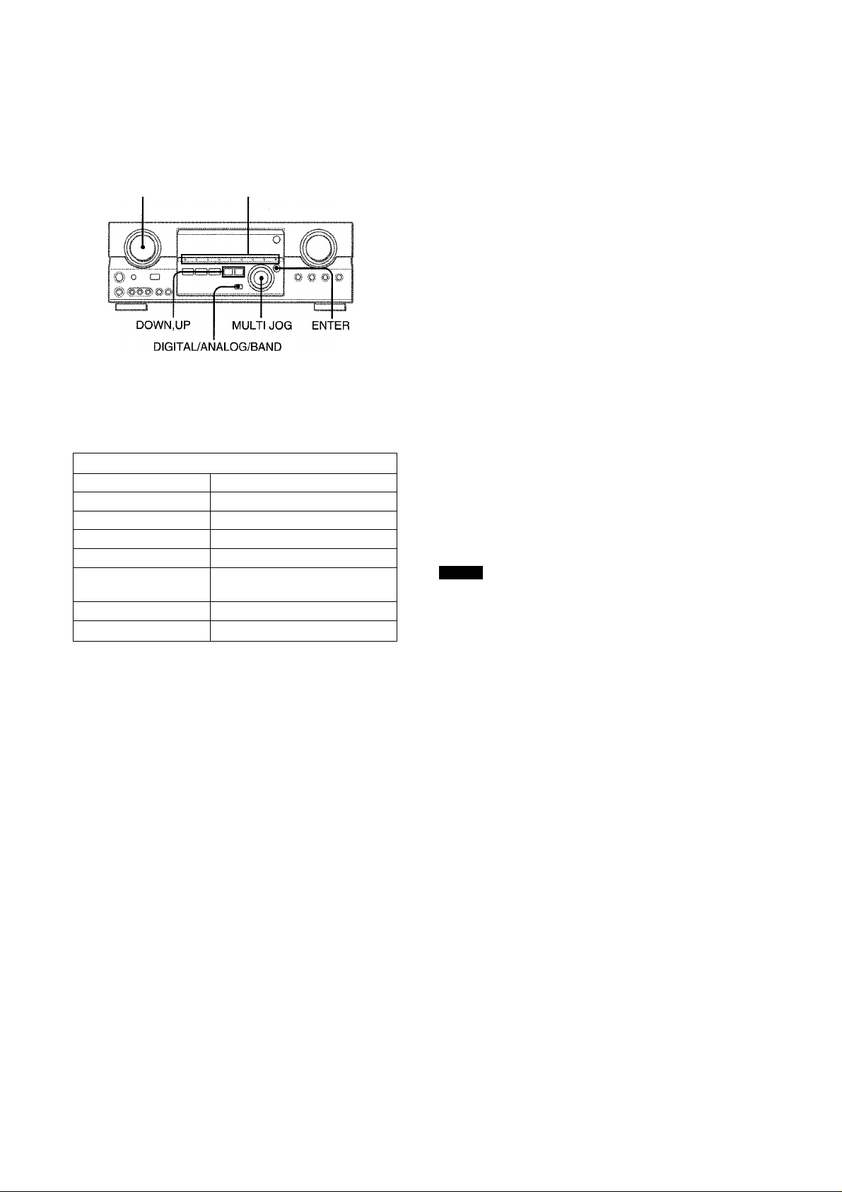
SELECTION OF AUDIO/VIDEO SOURCE
FUNCTION Function indicators
1 Select the program source.
Turn the FUNCTION selector or press the TAPE MONITOR
button. The selected function indicator iights in red.
To listen to or watch The indicator in red
Tape
Radio TUNER
Record
Compact disc CD
Television, etc. AUX
Video VIDEO 1/DVD/MD,
LD or Cable TV VIDEO 2/LD/TV
MD or DVD VIDEO 1/DVD/MD
The function to be seiected (except PHONO) depends on the
equipment connected to the input terminals on the rear panel
of the unit.
To select with the remote control
Press the TAPE MONITOR button or the FUNCTION button
repeatedly.
When using a turntable with a built-in equalizer amplifier, set
the switch of the equalizer amplifier to off. See the instructions
of the turntable for further information.
2 Start the selected program source.
3 Adjust the sound.
TAPE MONITOR
PHONO
VIDEO 2/LD/TV, VIDEO 3
]
To select the video source
1 Turn the FUNCTION to select PHONO, CD or AUX.
2 Press the ENTER button to display VIDEO 1.
3 Turn the MULTI JOG to select VIDEO 2 or VIDEO 3.
To change a displayed name for the VIDEO 1 and VIDEO 2
When the VIDEO 1 function is selected, VIDEO 1 is displayed
initially. It can be changed to DVD or MD.
Press the DIGITAL/ANALOG/BAND button while pressing the
ENTER button.
The displayed name for the VIDEO 2 function can be changed
to VIDEO 2, LD or TV; while the VIDEO 2 function is selected,
press the DIGITAL/ANALOG/BAND button while pressing the
ENTER button.
To select the “ANALOG” or “DIGITAL” (Dolby
Digital Surround) mode of the VIDE01, VIDEO
2 or VIDEO 3 function
Press the DIGITAL/ANALOG/BAND button when the VIDEO 1,
VIDEO 2 or VIDEO 3 is selected. The selected mode “ANALOG”
or “DIGITAL” appears on the display.
In the DIGITAL mode: Equipment connected to the OPTICAL
DIGITAL IN terminal is selected as a source for the VIDEO 1 or
VIDEO 3 function, and one connected to the COAXIAL DIGITAL
IN terminal for the VIDEO 2 function. The DIGITAL indicator
lights in red.
In the ANALOG mode: Equipment connected to the VIDEO 1/
DVD/MD IN or VIDEO 3 terminals is selected as a source for
the VIDEO 1 or VIDEO 3 function, and one connected to the
VIDEO 2/LD/TV terminals for the VIDEO 2 function.
NOTE
The “DIGITAL” mode changes to the “ANALOG,” when pressing
the TAPE MONITOR button.
When the “OVER LEVEL” indicator lights up
The unit is equipped with the OVER LEVEL indicator. When input
analog signals from the connected equipment are too high to
accept, the indicator lights on the right side of the display. In this
case, adjust the input level as mentioned below so that the
indicator disappears.
To adjust the sound level of the connected source
The input sensitivity level of each functioh can be adjusted
(except the TUNER, VIDEO 1 (DIGITAL), VIDEO 2 (DIGITAL)
and VIDEO 3 (DIGITAL) functions).
When the sound level of the connected source is higher or lower
than that of the TUNER, adjust it as follows.
1 Select the function to be adjusted.
Turn the FUNCTION or press the TAPE MONITOR button
and play the source.
About the video source to the monitor or TV
i'i"-:
V1: VIDEO 1, V2: VIDEO 2, V3: VIDEO 3
The selected video source is indicated on the display and the
video signal through the MONITOR VIDEO OUT jack is output
on the TV.
11
ENGLISH
I M
■■■
Selected video source
2 Press the UP or DOWN button repeatedly.
Adjust the level so that the “OVER LEVEL” indicator does
not light on the display.
• The level can be adjusted between -6dB (MIN) and +8dB
(MAX) in 2dB steps. Adjust the level so that the sound is
output at the same level as the TUNER.
• The input sensitivity level of the TAPE MONITOR can be
adjusted to OdB or -6dB.

TO PLAY A DVD OR LD RECORDED IN
DOLBY DIGITAL SURROUND
This receiver is equipped with the Doiby Digital decoder and
has the DIGITAL IN (both OPTICAL and COAXIAL) terminals.
When a DVD or LD player is connected to the DIGITAL IN terminal
of the receiver, you can enjoy theater-quality audio right in your
home Vi/hen playing discs recorded in Dolby Digital Surround.
Before operation
Check that the TAPE MONITOR is not selected. If the TAPE
MONITOR is selected, press the TAPE MONITOR button so that
“TAPE OFF” appears on the display.
1 Turn the FUNCTION to select the VIDEO 1 (VIDEO
2 or VIDEO 3) and press the DIGITAUANALOG/
BAND button repeatedly until “DIGITAL” is
dispiayed.
The DVD (LD) player connected to the OPTICAL (COAXIAL)
DIGITAL IN terminal is selected as a source.
Start piaying the DVD (LD) recorded in Doiby
Digitai Surround.
The “DOLBY DIGITAL” indicator will light on the display when
the bit stream of the Dolby Digital Surround comes in the
unit.
To select the Dolby Digital Surround mode according to your
speakers, see “SELECTING DOLBY SURROUND” on page
15.
NOT*
' While the TAPE MONITOR is selected and the TAPE MONITOR
indicator turns red, “DIGITAL” cannot be selected.
' When headphones are plugged in, the Dolby Digital Surround
mode is automatically changed to “2chSTEREO” and the “2CH
DOWNMIX” indicator lights on the display.
Even if the DOLBY SURROUND button is pressed while the
headphones are plugged in, the mode cannot be changed.
' This unit supperts input signals of the Dolby Digital Surround
bit stream and linear PCM whose sampling frequency is 32
kHz, 44.1 kHz and 48 kHz. The unit cannot play the DVDs whose
sampling frequency is 96 kHz.
' When connecting some DVD player to the receiver through the
DIGITAL IN terminals, noise may be heard in the DVD operation:
e.g. searching a disc, skipping a chapter.
RECORDiNG AN AUDiO SOURCE
ENTER
,)Y
Ì
ui:4.
0,0
j Liic:.cirr
...*r: *
MULTI JOG
' J - I
in,7:j
TAPE MONITOR
1 Select the pirogram source to be recorded.
Turn the FUNCTION.
2 Set the tape deck or MD recorder to the recording
mode.
3 Start the selected program source.
To monitor recorded sound during recording (when the
connected tape deck is a three-head system)
Press the TAPE MONITOR button. “TAPE ON” appears on the
display for four seconds, and then the source name selected in
step 1 comes back on. To cancel the tape monitor, press it again
so that “TAPE OFF” appears.
Any sound control system has no effect on recording (see
page 8).
Input sound through the DIGITAL IN terminals cannot be
recorded. When recording the sound from the DVD, CD, MD
or LD player, connect the analog AUDIO OUT terminals of
the player to the corresponding AUDIO IN terminals of the
receiver.
The sound will be recorded in 2 ch stereo.
When recording audio sources by the MD recorder connected
to the VIDEO 1/DVD/MD AUDIO OUT terminals, the selected
video source (see page 11) should be V2 or V3. Recording
cannot be done while the VI (VIDEO 1) is selected and
displayed on the window.
Input sound from the tape deck connected to the TAPE
MONITOR IN terminals cannot be recorded.
%,4H
.
......
’crJ
>U, O 'O. [
..
.1
(/}
z
g
CE
lU
Q.
O
g
CO
<
OQ
ENGLISH
12
t
I
MANUAL TUNING
MONO
TUNER
Turn the FUNCTION to select theTUNER function, and press the DIGITAUANALOG/BAND button repeatedly to select the desired band.
FM
-------
► AM ■
□
The display changes to frequency indications after indicating
band and video source (V1, V2 or V3) for two seconds.
Press the UP or DOWN button on the main unit to seiect a station.
Each time the button is pressed, the frequency changes.
When a station is received, “TUNE” is displayed for two
seconds. During FM stereo reception, (((®ill is displayed.
rPANCH ruvEl rHgn PahewaI_________
• •
To change the AM tuning interval
The default setting of the AM tuning interval is 10 kHz/step. If
you use this unit in an area where the frequency allocation
system is 9 kHz/step, change the tuning interval.
Hold down the DIGITAL/ANALOG/BAND button and press the
POWER button.
To reset the interval, repeat this procedure.
To search for a station quickly (Auto Search)
Keep the UP or DOWN button on the main unit pressed untii the
tuner starts searching for a station. After tuning in to a station,
the search stops.
To stop the Auto Search manually, press the UP or DOWN button.
• The Auto Search may not stop at stations with very weak
signals.
When an FM stereo broadcast contains noise
Press the MONO TUNER button on the remote control so that
“MONO” appears on the display.
Noise is reduced, although reception is monaural.
MONO
To restore stereo reception, press the button so that “STEREO”
appears.
When the reception contains noise interference
Move the unit away from other electrical appliances, especially
digital audio devices, or turn off the appliances that generate
noise signals.
1 3 ENGLISH
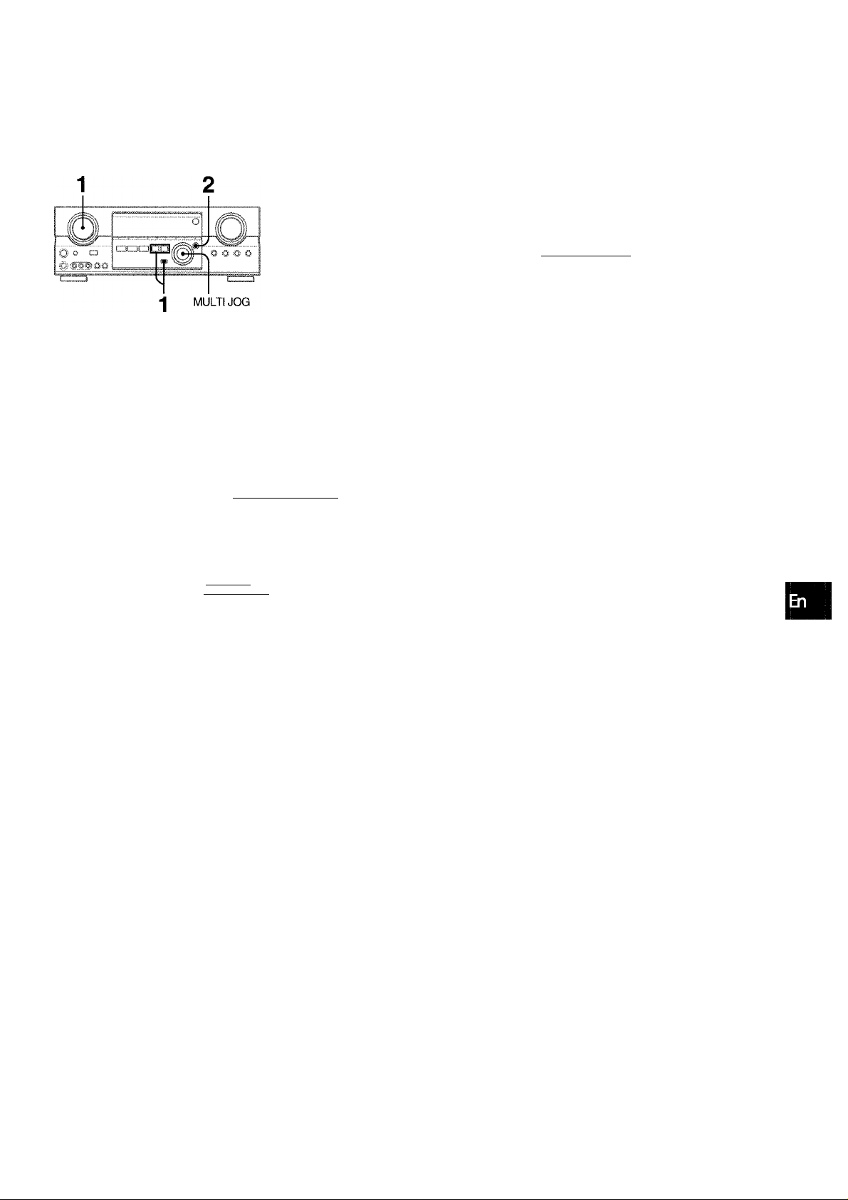
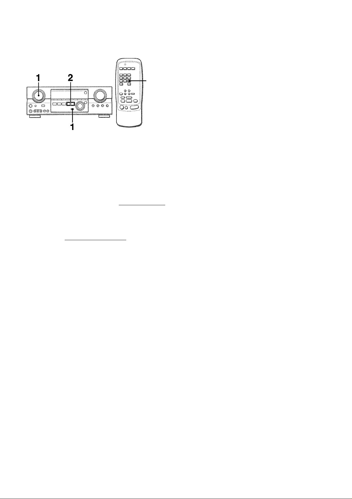
PRESEHING STATIONS
PRESET NUMBER TUNING
f - ^ ^
t2C3C
Q Q
i O O
OO Oc=a
1.1 f..- ?
1^0
Oo c,,„2
The unit can store a total of 32 preset stations. When a station is
stored, a preset number is assigned to the station. Use the preset
number to tune in to a preset station directly.
■DOWN.UP
1 Turn the FUNCTION to select theTUNER function,
and press the DIGITAL/ANALOG/BAND button
repeatedly to select the desired band. Then press
the UP or DOWN button to select a station.
2 Press the ENTER button on the main unit to store
the station.
A preset number assigned to the station, beginning from 1 in
consecutive order for each band, flashes in the display for
two seconds.
1 Turn the FUNCTION to select theTUNEFT functiom,
and press the DIGITAL/ANALOG/BAND button
repeatedly to select a band.
2 Turn the MULTI JOG to select a preset number.
To clear a preset station
Select the preset number of the station to be cleared. Then, press
the ENTER button on the main unit, and press it again within
four seconds.
The preset numbers of all other stations in the band with higher
numbers are decreased by one.
When using the remote control
Press UP^W or DOWNM< button to select a preset number.
Z
o
H
CL
LU
U
LU
QC
g
Q
!l! HALLI fAnÈNAl________________
il JAZZ! I CLASaiai BGMI
3 Repeat steps 1 and 2.
No more stations will be stored if a total of 32 stations have
already been stored for all the bands.
When the AM tuning interval is changed, all preset stations are
cleared. The preset stations have to be set again.
ENGLISH 14
I
This unit is equipped with not only the Dolby Pro Logic decoder
but also Dolby Digital decoder.
The unit and the center and surround speakers (standard) assure
full-scale home theater sound. When playing back discs or video
software that have been recorded in Dolby Pro Logic or Dolby
Digital Surround, astonishingly realistic sound surrounds the
listener to create a new level of audio/visual entertainment.
Independent control of the five channels allows the listener to
enjoy the same type of sound reproduction experienced in movie
theaters. Voices are reproduced in the front and center sound
field, while ambient sounds like cars and crowds are reproduced
on all sides of the listener for an incredibly lifelike audio/video
experience. Please read the following carefully to “tune” the
system’s output to match the characteristics of your listening
space.
TO SELECT A DOLBY SURROUND MODE
DOLBY SURROUND
Check the following:
• Before enjoying the DOLBY SURROUND sound, adjust the
speaker sound levels to the proper balance (see page 16).
• Make sure the speakers are properly connected and positioned
(see pages 4 and 5).
• Make sure the TV set and video unit are properly connected
(see page 3).
• Make sure the disc and video tape, etc., support Dolby Pro
Logic or Dolby Digital Surround.
SELECTING DOLBY SURROUND
The optimal Dolby Digital Surround and Dolby Pro Logic modes
and settings depend on the type and placement of the speakers.
It is recommended that the optional Aiwa speakers should be
used for all channels, for example, the SX-AVR2700 speaker
system.
Check the current type and placement of your speakers and select
the recommended mode accordingly.
The recommended mode
[Dolby Digital Surround]
Center speaker
Surround speaker
(Rear speaker)
No surround
speaker
[Dolby Pro Logic]
Surround speaker
(Rear speaker)
No surround
speaker
Larger-size
DOLBY
D-WIDE
3 STEREO
WIDE
Larger-size
PRO LOGIC
WIDE
3 STEREO
WIDE
Smaller-size No speaker
DOLBY
D-NORMAL
3 STEREO
NORMAL
Center speaker
Smaller-size
PRO LOGIC-
NORMAL
3 STEREO
NORMAL
PHANTOM
2chSTEREO
No speaker
PHANTOM
-
Preparations
• When selecting a Dolby Digital Surround mode, select the
VIDEO 1 (DIGITAL), VIDEO 2 (DIGITAL) or VIDEO 3 (DIGITAL)
function (see page 12)
Digital Surround before selecting the mode.
• When selecting a Dolby Pro Logic mode, select the function
except VIDEO 1 (DIGITAL), VIDEO 2 (DIGITAL) and VIDEO 3
(DIGITAL).
and play a disc recorded in Dolby
1 Press the DOLBY SURROUND button and turn
the MULTI JOG to select the appropriate mode.
The selected mode name appears on the display.
[Dolby Digital Surround]
DOLBY D
To select the 2chSTEREO mode, press the DOLBY
SURROUND button repeatedly until “2chSTEREO” appears.
PHANTOM 3 STEREO-
NOTE
Select the Dolby Digital Surround mode after playing a source
recorded in Dolby Digital Surround.
The Dolby Digital Surround mode cannot be selected:
• When using the unit for the first time
• After playing discs not recorded in Dolby Digital Surround
[Dolby Pro Logic]
PRO LOGIC -
PHANTOM 3 STEREO
[1
PHANTOM mode: Select this mode when the center speaker is
not connected. All center channel signals are redistributed to
the left and right channel speakers.
3 STEREO mode: Select this mode when the surround speakers
are not connected.
15 ENGLISH

Press the DOLBY SURROUND button again and
hold it down until the center speaker mode to be
selected appears. (Except the 2chSTEREO and
PHANTOM modes.)
“NORMAL” and “WIDE” appear one after the other.
When operating with the remote control
Press the DOLBY SURROUND button repeatedly to select the
mode, and hold it down to select the center speaker mode.
• Depending on the sound source or listening condition, surround
effect may not be obtained even when the Dolby Digital
Surround or Dolby Pro Logic is selected.
• The full Dolby Digital Surround or Dolby Pro Logic effect cannot
be obtained when using software not recorded in the Dolby
Digital Surround or Dolby Pro Logic system. In this case, use
the DSP surround system instead (see page 10).
• When headphones are plugged in:
- The Dolby Pro Logic system is automatically canceled.
- The Dolby Digital Surround mode is automatically changed
to “2chSTEREO.”
• While headphones are plugged in:
- The Dolby Pro Logic cannot be turned on.
- The Dolby Digital Surround mode cannot be changed.
ADJUSTING SPEAKER LEVEL
BALANCE
1
f.
The unit is equipped with a built-in test signal generator called a
noise sequencer for easy balance adjustment of all five channels.
The sequencer outputs a noise signal that “travels” from channel
to channel, enabling the simple adjustment of sound level to
achieve the same apparent loudness, at your listening position,
from each channel.
1 Select the Dolby Digital Surround (excepit
“2chSTEREO”) or Dolby Pro Logic mode
according to the current type and placement of
your speakers.
(See page 15.)
2 Press the MANUAL SELECT button on the remote
control and hold it down for about two seconds
until “L” of “L/R OdB” starts to flash.
2,4
Q
Z
3
o
cc
QC
zt
V)
>
m
A noise signal is sent to each channel in turn as follows:
DOLBY D (PRO LOGIC) NORMAL or WIDE mode
L/R OdB (Left front speaker)*
CEN OdB (Center speaker)
L/R OdB (Right front speaker)*
S-R OdB (Right surround speaker)
S-L OdB (Left surround speaker)
To be continued
ENGLISH
16

PHANTOM mode
L/R OdB*—► UR OdB'
I—► UR (
3-L OdB-<
I
-----
S-L(
3 STEREO NORMAL or WIDE mode
UR OdB* —► CEN OdB —► UR OdB’
----
S-R OdB
a
c;
□
To change the delay time of the surround speakers or
center speaker when using the Dolby Digital Surround
or Dolby Pro Logic mode
While the Dolby Digital Surround (except “2chSTEREO”) or Dolby
Pro Logic is activated, press the MANUAL SELECT button on
the remote control repeatedly so that “CEN OmS”or“SUR 5mS”
(SUR 20mS) is displayed. Then, within 4 seconds, press the UP
or DOWN button or turn the MULTI JOG. The delay time changes
as shown below.
* “L” or “R” flashes to indicate one of the front speakers from
which the noise signal is output.
3 Adjust the sound level of the center and surround
speakers.
While “CEN,” “S-L” or “S-R” flashes in the display, press the
UP or DOWN button on the remote control so that the sound
level of the center or surround speakers matches that of the
front speakers.
n
r.ill.'.sie.'.'.ii::!
The balance of the front speakers can be adjusted as well
while “UR” is displayed.
The UP or DOWN button on the main unit cannot be used.
4 Press the MANUAL SELECT button again to stop
the noise signal.
When adjusting the speaker level balance of the Dolby Digital
Surround, that of the Dolby Pro Logic is also changed and vice
versa.
About the channels
The left and right speakers create the stereo effect.
The center speaker helps precise sound positioning over a broad
sound field.
The rear-mounted surround speakers enhance the “depth” of
the sound field.
[Center speaker]
Adjust the delay time so that lines (voice in a movie) are heard
clearly and naturally.
The center speaker delay time is initially set to 0 ms
(milliseconds). It can be adjusted between 0 and 5 ms in 1 ms
step.
^
r'Ro'dk'irpoarjAgl-
O
0ms-«^1 ms-»2ms -»Sms -»4ms -»5ms
[Surround speakers]
Adjust the delay time to suite your preference.
Dolby Digital Surround
The speakers delay time is initially set to 5 ms. It can be adjusted
between 0 and 15 ms in 5 ms steps.
Dolby Pro Logic
The speakers delay time is initially set to 20 ms. It can be adjusted
between 15 and 30 ms in 5 ms steps.
NOTE
• When adjusting the delay time of the surround speakers or
center speaker for the Dolby Digital Surround, that of the Dolby
Pro Logic is changed and vice versa.
• When the surround speakers delay time of the Dolby Digital
Surround is set to 0 ms (5 ms, 10 ms , or 15 ms), that of the
Dolby Pro Logic is set to 15 ms (20 ms, 25 ms or 30 ms), and
vice versa.
To adjust the speaker level balance while listening to the source
The speaker level balance can be changed after adjusting it with
the noise sequencer. The balance can be changed whenever
the Dolby Digital Surround or Dolby Pro Logic system is activated.
17
1 Play a disc or video software recorded in Dolby Pro Logic or
Dolby Digital Surround.
2 Press the MANUAL SELECT button on the remote control
repeatedly so that “L/R,” “CEN,” “S-L” or “S-R” appears on the
display.
3 Press the UP or DOWN button or turn the MULTI JOG while
the speaker name to be adjusted is displayed.
ENGLISH

ADJUSTING DOLBY DIGITAL SURROUND SOUND
I CJ'J.U5
l J i
i i
aaaa
L laa
,aa»-
In- c
c- o
oo •>—
(!g ciL'
C
r-1
I ..«t.........ri.
5IE]l,
DOWN,UP
ENTER
ol
.............
J
-MANUAL
SELECT
■DOWN,UP
ADJUSTING DYNAMIC RANGE
Dynamic range of the Dolby Digital Surround sound can be
adjusted. The unit is initiaiiy set to the “STD” (standard) mode
1 While the Dolby Digital Surround is activated,
press the ENTER button on the main unit and hoLd
it down until “MID NIGHTTHEATER” runs through
on the display.
□
z
=)
o
cc
a:
3
(/)
>“
m
-I
o
Q
MULTI JOG
ADJUSTING LOW FREQUENCY SOUND
EFFECT(LFE)
The disc recorded in Dolby Digital Surround contains speciai
signals called LEE to enhance low frequency sound effect. The
LEE signals are recorded in some particuiar parts on the disc
and output from the connected sub-woofer to reproduce
astonishingiy powerfui low sound.
The sound level of the LEE signals can be adjusted according to
your speakers connected while the Dolby Digital Surround is
activated.
1 Press the UP or DOWN button and hold it down
until “LFE” is displayed.
2 Press the UP or DOWN button repeatedly or turn
the MULTI JOG to adjust the LFE level.
The unit is initially set to 0 dB (maximum) and can be adjusted
as shown below.
2 Press the UP or DOWN button or turn the MULTI
JOG to select the “MAX,” “STD” or “MIN” mode.
..............
[MIN]
You can enjoy the full dynamic range sound like in the movie
theater.
[STD]
Original position, when playing back in home, that is
recommended by the software producers.
[MAX]
Select this mode when playing back at low volume. This is
the mode when playing back in the mid night.
'^1
......
MIN** STD-«-MAX
...................................
.................
OEE**-20dB-
When not using a sub-woofer
While the Dolby Digital Surround (except “2chSTEREO”) is
activated, press the MANUAL SELECT button on the remote
control once so that “SUBW ON” is displayed. Then, press the
UP button or turn the MULTI JOG within 4 seconds to display
“SUBW OEE.” The LEE signals are redistributed to the other
speakers.
To restore, press the MANUAL SELECT button once so that
“SUBW' OEE” is displayed, then press the DOWN button or turn
the MULTI JOG to display “SUBW ON.”
NOTE
When setting the sub-woofer mode of the Dolby Digital Surround
to “SUBW OEE,” that of the Dolby Pro Logic is also set to “SUBW
OEE,” and vice versa. In this case, the sub-woofer signals are
redistributed to the other speakers.
-10dB**0dB
ENGLISH 18
I
OPERATING TV, CABLE TV, VCR
AND CD PLAYER
You can control basic functions of a TV, CABLE TV, VCR and CD
player with this remote control.
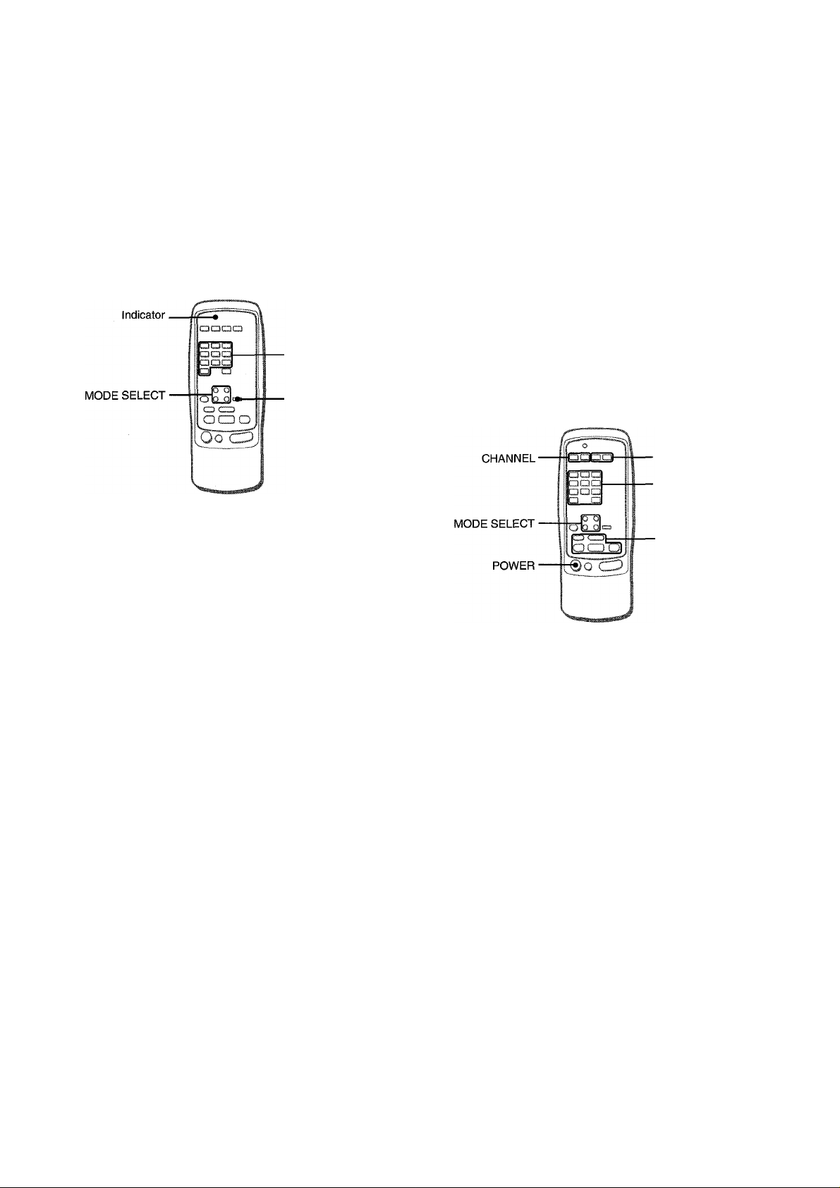
TO ENTER THE ID CODE OF THE EXTERNAL EQUIPMENT
. DIGIT buttons
(0~9)
■ SET UP
To confirm the stored ID code
You can check the stored ID code by counting the indicator blinking.
1 Press either the TV, CABLE, VCR or CD button.
For example, to check the stored code for CD player, press
CD.
2 Press and hold the SET UP button for about 2.5 seconds. 3 Press “9,” “9” and “0.” 4 Press “1,” and count the indicator blinks.
For example, in the case that the stored ID is “157.”
The indicator blinks once.
5 Press “2,” and count the indicator blinks.
The indicator blinks five times.
6 Press “3,” and count the indicator blinks.
The indicator blinks seven times.
TO CONTROL TV, CABLE TV, VCR AND CD PLAYER
■ VOLUME
■ DIGIT buttons
(0~9) and ENTER
Before attempting to control them, be sure to enter the ID code
of the external equipment to the remote control as follows.
1 Confirm the code number of the external
equipment.
See the ID code list in the “APPENDIX” at the end of this
manual.
2 Press either the TV, CABLE, VCR or CD button in
the MODE SELECT area.
3 Press and hold the SET UP button for about 2.5
seconds.
Confirm that the indicator blinks twice while pressing the SET
UP button.
4 Press three DIGIT buttons which correspond to
the ID code of the external equipment.
For example, if your CD player is an AIWA unit, the required
ID code is 124 or 157. In this case, press the DIGIT buttons in
the order of “1,” “2” and “4” (or “1,” “5” and “7”),
After the third DIGIT button is pressed, the indicator blinks
twice indicating that the ID code is correct and is stored on
the remote control.
VCR/CD
ll:Pause,B:Stop,
¡◄◄iRewind,
►'.Play,
►W: Fast forward
1 Press any button in the MODE SELECT area (TV,
CABLE, VCR or CD).
The remote control is ready to operate the selected mode
equipment.
2 Press one of the buttons indicated above.
For the use of the 0 - 9 and the ENTER buttons, see the
instruction manual supplied with the unit to be controlled.
Other buttons Indicated above have the same function which
you will find on the unit to be controlled.
■ Reenter the ID CODE of the external equipment after replacing
the batteries of the remote control.
' If there are plural ID codes for external equipment in the
“APPENDIX," try each number listed until you can control the
external equipment.
19
ENGLISH

SEHING THE CLOCK
SEHING THE SLEEP TIMER
o
cc
2 1,3
i I3CJQ
a
(
Q a
i-'i: r
U i<' Q
DIGITAL/ANALOG/BAND
When the AC cord is connected for the first time, the ciock on
the dispiay flashes.
Set the time as follows while the power is off.
ud Q O
iii
Jf-JQ
1 Press the ENTER button on the main unit.
The display becomes a little brighter.
2 Turn the MULTI JOG to designate the hour and
the minute.
The time advances by turning it to right, and decreases by
turning it to left.
The DOWN or UP button on the main unit is also available.
Press the button repeatedly. To change the time rapidly in
10-minute steps, hold it down.
•CLOCK
aS§
o o
® a i
UP,
DOWN
The receiver can be automatically turned off at a specified time.
1 Press the AIWA RECEIVER button. 2 Press the SL.EEP button.
The unit will be turned off after about 60 minutes.
To specify the time until the power is turned off
Press the UP or DOWN button repeatedly within four seconds
after step 2.
Each time the button is pressed, the time changes between 5
and 240 minutes in 5-minute steps.
Ie
oSs
LU
IT
3 Press the ENTER button on the main unit.
The clock starts from 00 seconds.
When the clock is set for the first time after purchase
Everything on the display will clear.
This is because the power economizing mode of the unit is
activated, and is not a malfunction.
The power economizing mode can be canceled. See page 7 for
details.
To correct the current time
Press the POWER button to turn the unit off. Carry out steps 1
to 3 above.
To display the current time
Press the CLOCK button on the remote control. The clock is
displayed for 4 seconds.
To switch to the 24-hour standard
While the power is on, press the CLOCK button on the remote
control to display the clock. Then press the DIGITAL/ANALOG/
BAND button while the clock is displayed.
Repeat the same procedure to restore the 12-hour standard.
If the clock display flashes while the power Is off
This is caused by a power interruption. The current time needs
to be reset.
If power is interrupted for more than approximately 24 hours, all
settings stored in memory after purchase need to be reset.
Specified time
To check the time remaining until the power is turned off
Press the SLEEP button once. The remaining time is displayed
for four seconds.
To cancel the sleep timer
Press the SLEEP button twice so that “SLEEP” on the display
disappears.
ENGLISH
20

SPECIFICATIONS
FM tuner section
Tuning range 87.5 MHz to 108 MHz
Usable sensitivity 13.2 dBf
(IHF)
Antenna terminals 75 ohms (unbalanced)
AM tuner section
Tuning range 530 kHz to 1710 kHz (10 kHz step),
531 kHz to 1602 kHz (9 kHz step)
Usable sensitivity 350 pV/m
Antenna Loop antenna
Amplifier section
Power output [Stereo Mode]
Front
170 watts per channel, Min. RMS at 8
ohms, from 40 Hz to 20 kHz, with no
more than 0.9% Total Harmonic
Distortion
[Dolby Digital Surround or Dolby
Pro Logic Mode]
Front
120 watts per channel, Min. RMS at 8
ohms, from 40 Hz to 20 kHz, with no
more than 0.9% Total Harmonic
Distortion
Rear (Surround)
120 watts per channel, Min. RMS at 8
ohms, 1 kHz, with no more than 0.9%
Total Harmonic Distortion
Center
120 watts, Min. RMS at 8 ohms, 1
kHz, with no more than 0.9% Total
Harmonic Distortion
Total harmonic
distortion
Inputs
0.15 % (85 W, 1 kHz, 8 ohms. Front)
AUDIO IN
PHONO: 2.5 mV, adjustable (47
kohms)
CD: 250 mV, adjustable (47
kohms)
TAPE MONITOR: 350 mV,
adjustable (47 kohms)
VIDEO 1/DVD/MD, VIDEO 2/LD/
TV, VIDEO 3,AUX: 250 mV,
adjustable (47 kohms)
DIGITAL IN
COAXIAL (VIDEO 2):
OPTICAL (VIDEO 1):
OPTICAL (VIDEO 3):
accept linear PCM (32 kHz, 44.1
kHz and 48 kHz) signals and bit
stream of Dolby Digital Surround
VIDEO IN: 1 Vp-p (75 Ohms)
Outputs
Muting
AUDIO OUT (REC OUT): 200 mV (1
kohm)
VIDEO OUT (MONITOR): 1 Vp-p (75
ohms)
SUPER WOOFER: 5.0 V
FRONT SPEAKERS IMP: 80/40
selectable (front speakers A and B):
with the SPEAKER IMPEDANCE
SELECTOR set to 40, accepts
speakers of 4 ohms,
with the SPEAKER IMPEDANCE
SELECTOR set to 80, accepts
speakers of 8 ohms or more.
SURROUND SPEAKERS IMP: 80
(surround speakers): accepts
speakers of 8 ohms or more
CENTER SPEAKER IMP: 80/40
selectable
with the SPEAKER IMPEDANCE
SELECTOR set to 40, accepts
speaker of 4 ohms,
with the SPEAKER IMPEDANCE
SELECTOR set to 80, accepts
speaker of 8 ohms or more.
PHONES (stereo jack): accepts
headphones of 32 ohms or more
-20 dB
General
Power requirements
Power consumption
Dimensions
(W X H X D)
Weight
Specifications and external appearance are subject to change
without notice.
HUE SYSTEM
The word “BBE” and the “BBE symbol” are trademarks of BBE
Sound, Inc.
Under license from BBE sound, Inc.
Manufactured under license from Dolby Laboratories.
“Dolby”, “Pro Logic” and the double-D symbol are trademarks of
Dolby Laboratories. Confidential Unpublished Works. ©1992
1997 Dolby Laboratories, Inc. All rights reserved.
120 VAC, 60 Hz
230 W
430 X 155 X 385 mm
(17x6 Vs x15 V4 in.)
12 kg (26 lb7oz.)
21
ENGLISH
 Loading...