

Page 1
I
For assistance and information
\8-ARl-903-01
180401 CCK-Y-9
I
call toll free I-800-BUY4WA
(United States and Puerto Rico)
Page 2
“CAUTION:TO REDUCE THE RISK OF
ELECTRIC SHOCK,
DO NOT REMOVE COVER (OR BACK).
NO USER-SERVICEABLE PARTS INSIDE.
REFER SERVICING TO QUALIFIED
SERVICE PERSONNEL.”
PRECAUTIONS
Read the Operating Instructions carefully and completely before
operating the unit. Be sure to keep the Operating Instructions
for future reference. All warnings and cautions in the Operating
Instructions and on the unit should be strictly followed, as well
as the safety suggestions below.
Installation
Water and moisture — Do not use this unit near water, such
1
as near a bathtub, washbowl, swimming pool, or the like.
2
Heat — Do not use this unit near heat sources, including
heating vents, stoves, or other appliances that generate heat.
It also should not be placed in temperatures less than 5°C
(41”F) or higher than 35°C (95”F).
3
Mounting surface — Place the unit on a flat, even surface.
Ventilation — The unit should be situated with adequate
4
space around it so that proper heat ventilation is assured.
Allow 10 cm (4 in.) clearance from the rear and the top of the
unit, and 5 cm (2 in.) from each side.
- Do not place the unit on a bed, rug, or similar surface that
may block the ventilation openings.
- Do not install the unit in a bookcase, cabinet, or airtight
rack where ventilation may be impeded.
Objects and liquid entry — Take care that objects or liquids
5
do not get inside the unit through the ventilation openings.
Carts and stands — When placed or
6
mounted on a stand or cart, the unit
should be moved with care.
Quick stops, excessive force, and
uneven surfaces may cause the unit or
cart to overturn or fall.
7
Wall or ceiling mounting —The unit should not be mounted
on a wall or-ceiling, u;less specified in the Operating
Instructions.
●3
m
AA*
Owner’s record
For your convenience, record the model number and serial
number (you will find them on the rear of your unit) in the space
provided below. Please refer to them when you contact your
Aiwa dealer in case of difficulty.
Model No. Serial No. (Lot No.)
AV-DV70
Power sources — Connect this unit only to power sources
1
specified in the Operating Instructions, and as marked on
the unit.
2
Polarization — As a safety feature, some units are equipped
with polarized AC power plugs which can only be inserted
one way into a power outlet. If it is difficult or impossible to
insert the AC power plug into an outlet, turn the plug over
and try again. If it is not still inserted easily into the outlet,
pIease call a qualified service technician to service or replace
the outlet. To avoid defeating the safety feature of the
polarized plug, do not force it into a power outlet.
3
AC power cord
- When disconnecting the AC power cord, pull it out by the
AC power plug. Do not pull the cord itself.
- Never handle the AC power plug with wet hands, as this
could result in fire or shock.
- Power cords should be firmly secured to avoid being
severely bent, pinched, or walked upon. Pay particular
attention to the cord from the unit to the power socket.
- Avoid overloading AC power plugs and extension cords
beyond their capacity, as this could result in fire or shock.
4
Extension cord — To help prevent electric shock, do not
use a polarized AC power plug with an extension cord,
receptacle, or other outlet unless the polarized plug can be
completely inserted to prevent exposure of the blades of the
plug.
When
5
not in use — Unplug the AC power cord from the AC
power outlet if the unit will not be used for several months or
more. When the cord is plugged in, a small amount of current
continues to flow to the unit, even when the power is turned
off.
1 ENGLISH
Page 3
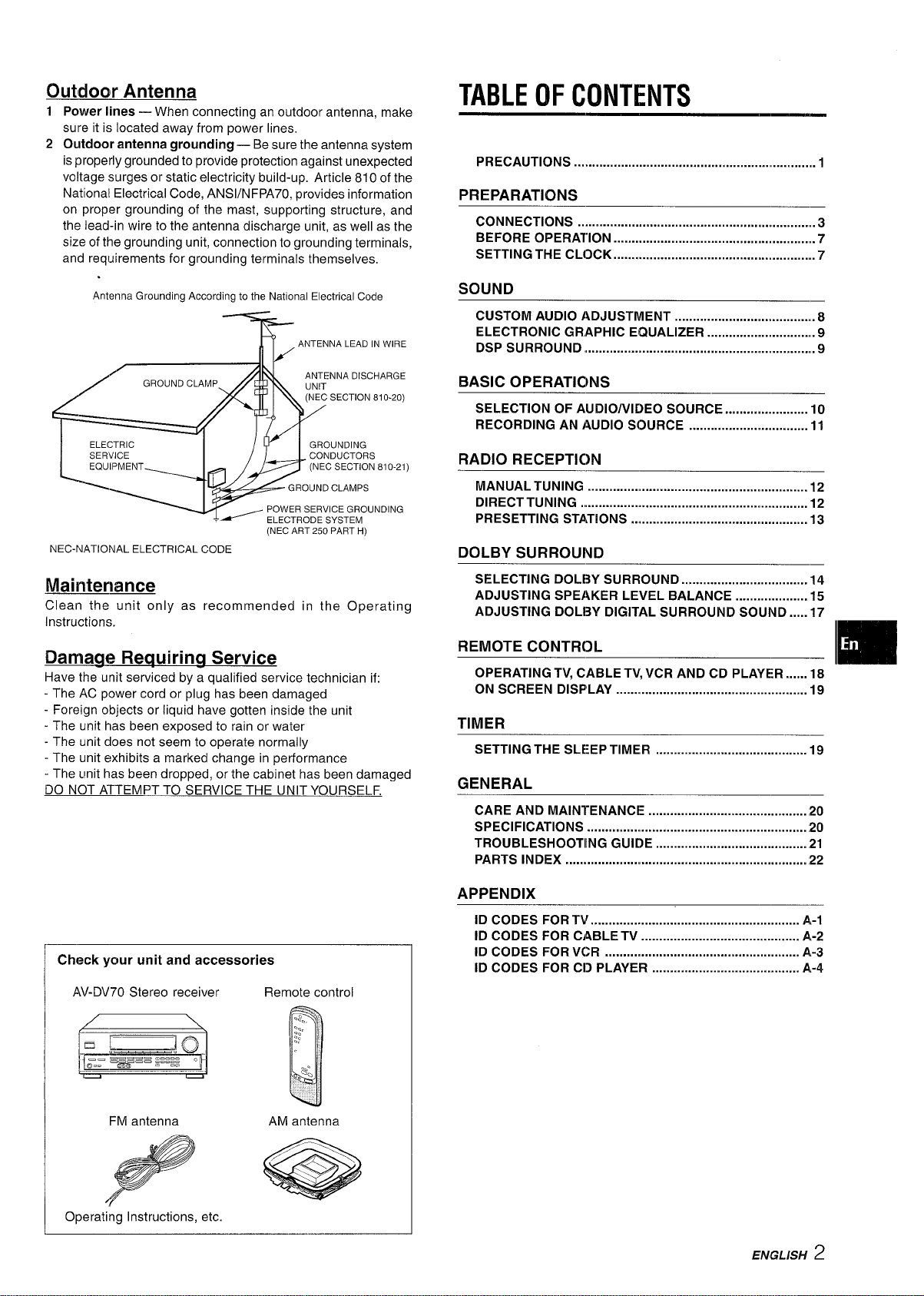
Outdoor Antenna
1 Power lines — When connecting an outdoor antenna, make
sure it is located away from power lines,
2 Outdoor antenna grounding — Be sure the antenna system
is properly grounded to provide protection against unexpected
voltage surges or static electricity build-up. Article 810 of the
National Electrical Code, ANS1/NFPA70, provides information
on proper grounding of the mast, supporting structure, and
the lead-in wire to the antenna discharge unit, as well as the
size of the grounding unit, connection to grounding terminals,
and requirements for grounding terminals themselves,
TABLE (IF CONTENTS
PRECAUTIONS . . . . . . . . . . . . . . . . . . . . . . . . . . . . ..m . . . . . . . . . . . . . . . . . . . . . . . . . . . . . . . . . . . . I
PREPARATIONS
CONNECTIONS .................................................................. 3
BEFORE OPERATION ........................................................ 7
SETTING THE CL[3CK .........................................................7
Antenna Grounding According to the National Electrical Code
(NECART250PARTH)
NEC-NATIONAL ELECTRICALCODE
Maintenance
Clean the unit only as recommended in the Operating
Instructions.
Damaae Reauirina Service
Have the unit serviced by a qualified service technician if:
- The AC power cord or plug has been damaged
- Foreign objects or liquid have gotten inside the unit
- The unit has been exposed to rain or water
- The unit does not seem to operate normally
- The unit exhibits a marked change in performance
- The unit has been dropped, or the cabinet has been damaged
DO NOT ATTEMPT TO SERVICE THE UNIT YOURSELF.
SOUND
CUSTOM AUDIO ADJUSTMENT ..................................... . 8
ELECTRONIC GRAPHIC EQUALIZER ............................ . 9
DsPsuRRouND .............................................................m....9
BASIC OPERATICINS
SELECTION OF AUDIO/VIDEO SOURCE ....................... 10
RECORDING AN AUDIO SOURCE ................................. 11
)
RADIO RECEPTIC)N
MANUAL TUNING .............. .............................................. 12
DIRECT TUNING ............................................................... 12
PRESETTING STATIONS ................................................. 13
DOLBY SURROUND
SELECTING DOLE3Y SURROUND ................................... 14
ADJUSTING SPEAKER LEVEL BALANCE .................... 15
ADJUSTING DOL13Y DIGITAL SURROUND SOUND .....17
REMOTE CONTROL
OPERATING TV, CABLE TV, VCR AND CD PLAYER ......18
ON SCREEN DISPLAY ..................................................... 19
.
m
TIMER
SETTING THE SLEEP TIMER . . . . . . . . . . . . . . . . . . . . . . . . . . . . . . . . . . . . . . . . . . 19
GENERAL
CARE AND MAINTENANCE ............................................ 20
SPECIFICATIONS ............................................................. 20
TROUBLESHOOTIING GUIDE
PARTS INDEX ...............m..................................................m22
. . . . . . . . . . . . . . . . . . . . . . . . . . . . . . . . . . . . . . . . . . 21
Check
your unit and accessories
AV-DV70 Stereo receiver Remote control
FM antenna
Operating Instructions, etc.
AM antenna
APPENDIX
ID CODES FOR Tir .......................................................... A-1
ID CODES FOR CABLE TV ............................................ A-2
ID CODES FOR VCR ...................................................... A-3
ID CODES FOR CD PLAYER ......................................... A,-4
EMGLBH
2
Page 4
CONNECTIONS
Before connecting the AC cord
The rated voltage of your unit shown on the rear panel is 120 V
AC. Check that the rated voltage matches your local voltage.
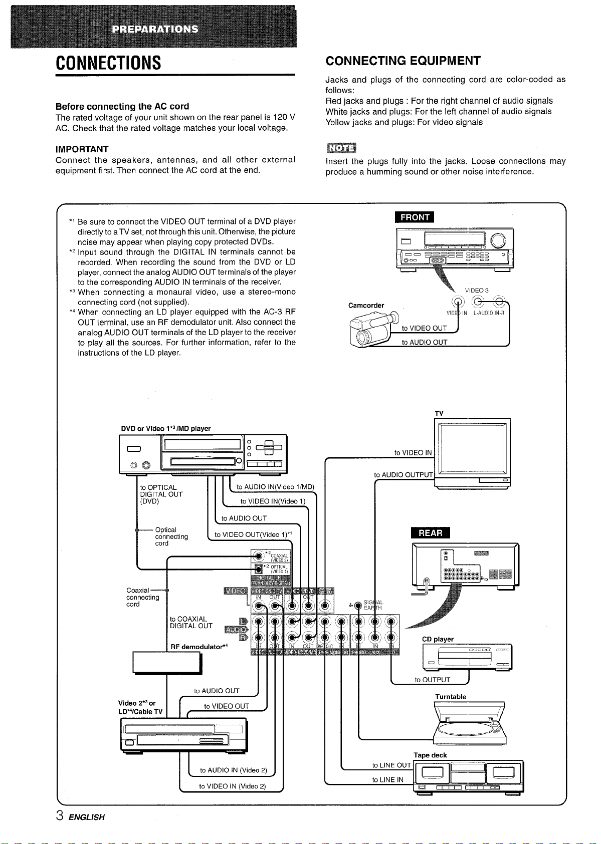
CONNECTING EQUIPMENT
Jacks and plugs of the connecting cord are color-coded as
follows:
Red jacks and plugs : For the right channel of audio signals
White jacks and plugs: For the left channel of audio signals
Yellow jacks and plugs: For video signals
IMPORTANT
Connect the speakers, antennas, and all other external
equipment first. Then connect the AC cord at the end.
*’ Be sure to connect the VIDEO OUT terminal of a DVD player
directly to aTV set, not through this unit. Otherwise, the picture
noise may appear when playing copy protected DVDS.
‘2 Input sound through the DIGITAL IN terminals cannot be
recorded, When recording the sound from the DVD or LD
player, connect the analog AUDIO OUT terminals of the player
to the corresponding AUDIO IN terminals of the receiver.
‘3 When connecting a monaural video, use a stereo-mono
connecting cord (not supplied).
‘4 When connecting an LD player equipped with the AC-3 RF
OUT terminal, use an RF demodulator unit. Also connect the
analog AUDIO OUT terminals of the LD player to the receiver
to play all the sources. For further information, refer to the
instructions of the LD player.
DVD or Video 1*3IMD
I
1(—1 o . 1
player
m
Insert the plugs fully into the jacks. Loose connections may
produce a humming sound or other noise interference.
= ~~
mm ~Rmuu .—=... o
Q“” C@l===
+
c=
to VIDEO IN
V;DZQ3
TV
Optical
connecting 1cord “
I
(
Coaxial---4
connecting
I
I
Video 2*3or
LDWCable TV G=J
I
to COAXIAL
“G’TAL ‘UT +
RF demodulator*4
I Ill
IL
to VIDEO OUT(Video
I .- ..” )11
7 mF
L
.
I
!
to AUDIO IN (Video 2)
to VIDEO IN (Video2)
1)“
1111
Ill
I
c
w I
to AUDIO OUTPUT
d
CD player
-
A
Turntable
3 ENGLISH
Page 5
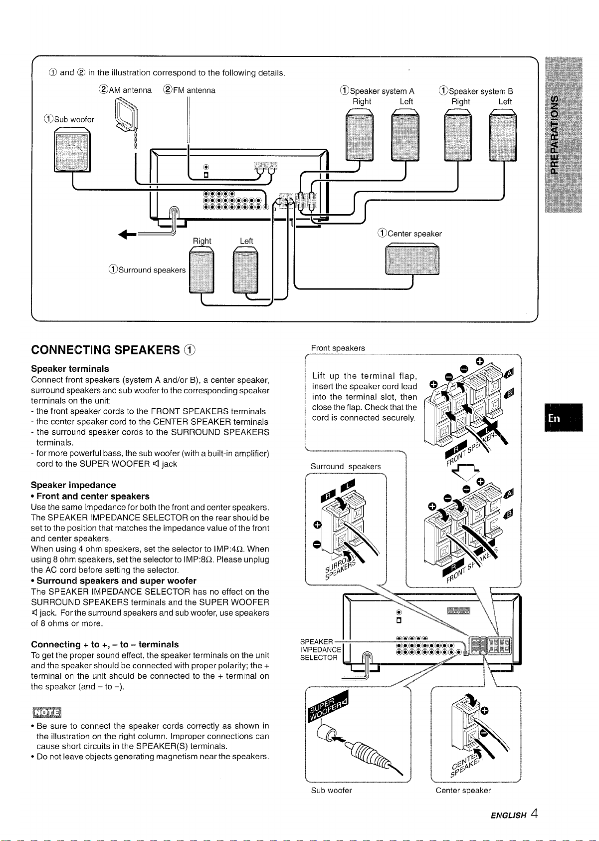
CONNECTING SPEAKERS @
Front sneakers
Speaker terminals
Connect front speakers (system A and/or B), a center speaker,
surround speakers and sub woofer to the corresponding speaker
terminals on the unit:
- the front speaker cords to the FRONT SPEAKERS terminals
- the center speaker cord to the CENTER SPEAKER terminals
- the surround speaker cords to the SURROUND SPEAKERS
terminals,
- for more powerful bass, the sub woofer (with a built-in amplifier)
cord to the SUPER WOOFER d jack
Speaker impedance
* Front and center speakers
Use the same impedance for both the front and center speakers.
The SPEAKER IMPEDANCE SELECTOR on the rear should be
set to the position that matches the impedance value of the front
and center speakers.
When using 4 ohm speakers, set the selector to IMP:4L2. When
using 8 ohm speakers, set the selector to IMP:8Q, Please unplug
the AC cord before setting the selector,
* Surround speakers and super woofer
The SPEAKER IMPEDANCE SELECTOR has no effect on the
SURROUND SPEAKERS terminals and the SUPER WOOFER
4 jack. For the surround speakers and sub woofer, use speakers
of 8 ohms or more.
Connecting + to +, – to – terminals
To get the proper sound effect, the speaker terminals on the unit
and the speaker should be connected with proper polarity; the +
terminal on the unit should be connected to the + terminal on
the speaker (and – to –).
Lift up the terminal flap,
insert the speaker cord lead
into the terminal slot, then
close the flap. Check that the
cord is connected securely.
Surround speakers
SELECTOR
.
.—
—r——————
“e
m
* Be sure to connect the speaker cords correctly as shown in
the illustration on the right column. Improper connections can
cause short circuits in the SPEAKER(S) terminals.
● Do not leave objects generating magnetism near the speakers.
ENGLISH’4
Page 6
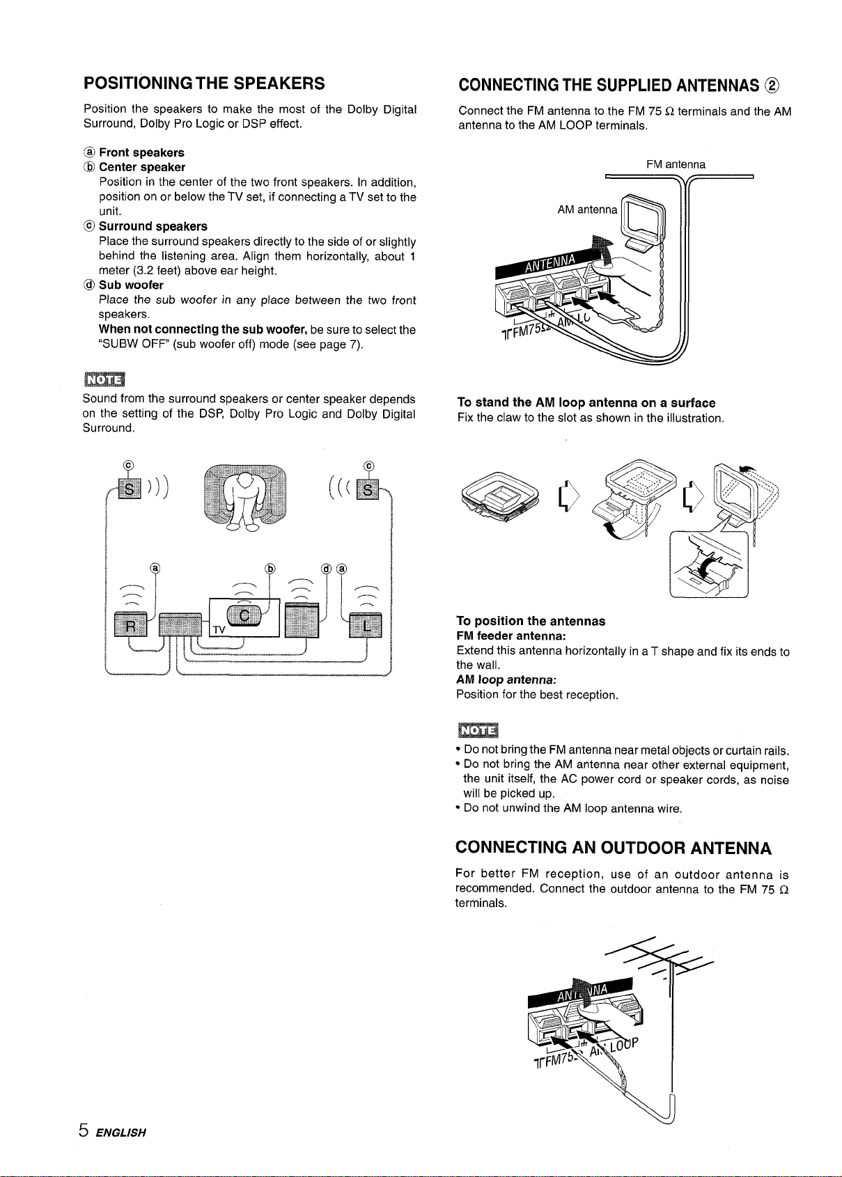
POSITIONING THE SPEAKERS
Position the speakers to make the most of the Dolby Digital
Surround, Dolby Pro Logic or DSP effect.
CONNECTING THE SUPPLIED ANTENNAS @
Connect the FM antenna to the FM 75 Q terminals and the AM
antenna to the AM LOOP terminals.
@ Front speakers
@ Center speaker
Position in the center of the two front speakers. In addition,
position on or below the TV set, if connecting a TV set to the
unit.
@ Surround speakers
Place the surround speakers directly to the side of or slightly
behind the listening area. Align them horizontally, about 1
meter (3.2 feet) above ear height.
@
Sub woofer
Place the sub woofer in any place between the two front
speakers.
When not connecting the sub
“SUBW OFF (sub woofer off) mode (see page 7).
m
Sound from the surround speakers or center speaker depends
on the setting of the DSP, Dolby Pro Logic and Dolby Digital
Surround,
woofer, be sure to select the
FM antenna
)
\v
To stand the AM loop antenna on a surface
Fix the claw to the slot as shown in the illustration.
(
@ @
69(9
To position the antennas
FM feeder antenna:
Extend this antenna horizontally in a T shape and fix its ends to
the wall.
AM loop antenna:
Position for the best reception.
● Do not bring the FM antenna near metal objects or curtain rails.
● Do not bring the AM antenna near other external equipment,
the unit itself, the AC power cord or speaker cords, as noise
will be picked up.
● Do not unwind the AM loop antenna wire.
CONNECTING AN OUTDOOR ANTENNA
For better FM reception, use of an outdoor antenna is
recommended. Connect the outdoor antenna to the FM 75 Q
terminals.
5 ENGLISH
Page 7
USINGI WITH TV
‘uNcT’ON-evOLuM
When you operate the receiver, you can check the receiver
settings on the TV screen, if the connected TV is turned on (On
Screen Display function). The following screen shows the sound
effect settings of the Dolby Digital Surround.
For the further details, see “ON SCREEN DISPLAY” on page
DOLBY DGTL SU~N NORMAL
SUBW
L LVL MAX
CEN LVL
~R ~!k OdB
SL LVL OdB
OdE
MAX
CEN DELAY Orns
SUR DELAY 5ms
LFE LVL
MIDNIGHT STD
● The TV screen turns to blue if the TV signal or video signal
sent from the VCR/camcorder is weak or unlocked to the sync
signal. The screen restores the proper indication when the TV/
video signal turns to good condition.
● The video recording (connected to the VIDEO OUT jack of the
unit) is not affected by the screen indication, even if the screen
has changed to blue.
OdB
AB3UTTHE REMOTE CONTROL
Inserting batteries
Detach the battery cover on the rear of the remote control and
insert two R6 (size AA) batteries.
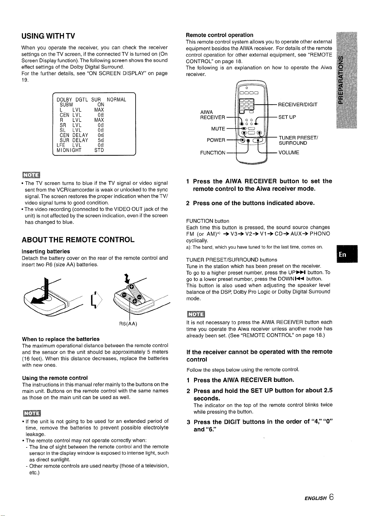
Remote control operation
This remote control system allows you to operate other external
equipment besides the AIWA receiver. For details of the rennote
control operation for other external equipment, see “REMOTE
CONTROL” on page 18.
The following is an explanation on how to operate the Aiwa
receiver.
C=l
RECEIVER/DIGIT
AIWA
RECEIVER —
MUTE —
POWER —
SET UP
TUNER PRESET/
SURROUND
1
Press the AIWA RECEIVER button ta set the
remote controll to the
Press one of the buttons indicated above.
2
FUNCTION button
Each time this button is pressed, the sound source changes
FM (or AM)’) +V3+V2+V1+CD+AUX+ PHOIVO
cyclically.
a): The band, which you have tuned to for the last time, cotmes on.
TUNER PRESET/S~JRROUND buttons
Tune in the station which has been preset on the receiver.
To go to a higher preset number, press the UP~ button. To
go to a lower preset number, press the DOWN 1+1 button.
This button is also used when adjusting the speaker level
balance of the DSP, Dolby Pro Logic or Dolby Digital Surround
mode.
Aiwa receiver mode.
❑
R6(AA)
When to replace the batteries
The maximum operational distance between the remote control
and the sensor on the unit should be approximately 5 meters
(16 feet). When this distance decreases, replace the batteries
with new ones.
Using the remote control
The instructions in this manual refer mainly to the buttons on the
main unit. Buttons on the remote control with the same names
as those on the main unit can be used as well.
c If the unit is not going to be used for an extended period of
time, remove the batteries to prevent possible electrolyte
leakage.
● The remote control may not operate correctly when:
- The line of sight between the remote control and the remote
sensor in the display window is exposed to intense light, such
as direct sunlight.
- Other remote controls are used nearby (those of a television,
etc.)
It is not necessary to press the AIWA RECEIVER button each
time you operate the Aiwa receiver unless another mode has
already been set. (See “REMOTE CONTROL” on page 18.)
If the receiver cannot be operated with the remote
control
Follow the steps below using the remote control.
1
Press the AIWA RECEIVER button.
Press and hold the SET UP button for -about 2.5
2
seconds.
The indicator on the top of the remote control blinks twice
while pressing this button.
Press the DIGIT buttons in the order of “4;’ “O”
3
and “6.”
ENGLISH 6
Page 8
BEFORE OPERATION
SETTING THE CLOCK
DOLBY SURROUND
IER MANUAL SELECT
Po
II Function indicators
I
PHONES
TAPE MONITOR
I
FRONT SPEAKERS A, B
VOLUME
I
Function
buttons
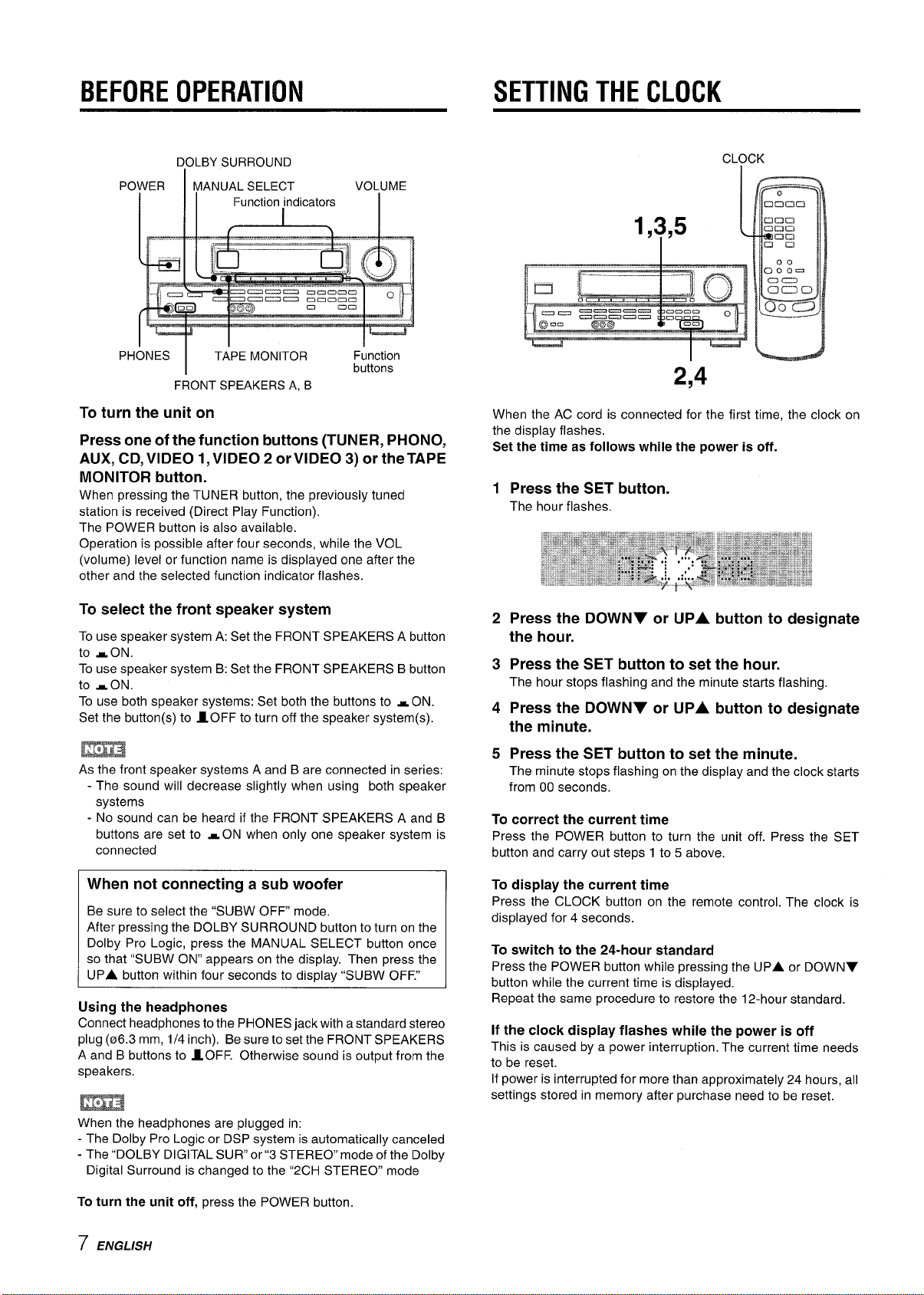
To turn the unit on
Press one of the function buttons (TUNER, PHONO,
AUX, CD, VIDEO I, VIDEO 2 or VIDEO 3) or the TAPE
MONITOR button.
When pressing the TUNER button, the previously tuned
station is received (Direct Play Function).
The POWER button is also available,
Operation is possible after four seconds, while the VOL
(volume) level or function name is displayed one after the
other and the selected function indicator flashes.
CLOCK
,y,5
1
2,4
When the AC cord is connected for the first time, the clock on
the display flashes.
Set the time as follows while the power is off.
1
Press the SET button.
The hour flashes.
To select the front speaker system
To use speaker system A: Set the FRONT SPEAKERS A button
to -ON.
To use speaker system B: Set the FRONT SPEAKERS B button
to sON.
To use both speaker systems: Set both the buttons to ~ ON.
Set the button(s) to 10FF to turn off the speaker system(s).
m
As the front s~eaker svstems A and B are connected in series:
- The sound will dec;ease slightly when using both speaker
systems
- No sound can be heard if the FRONT SPEAKERS A and B
buttons are set to -ON when only one speaker system is
connected
When not connecting a sub woofer
Be sure to select the “SUBW OFF mode.
After pressing the DOLBY SURROUND button to turn on the
Dolby Pro Logic, press the MANUAL SELECT button once
so that “SUBW ON” appears on the display. Then press the
UPA button within four seconds to displav “SUBW OFF.”
Using the headphones
Connect headphones to the PHONES jack with a standard stereo
plug (06.3 mm, 1/4 inch). Be sure to set the FRONT SPEAKERS
A and B buttons to AOFF. Otherwise sound is output from the
speakers.
2
Press the DOWNY or UPA button to designate
the hour.
Press the SET button to set the hour.
3
The hour stops flashing and the minute starts flashing,
4
Press the DOWNV or UPA button to designate
the minute.
5 Press the SET button to set the minute.
The minute stops flashing on the display and the clock starts
from 00 seconds.
To correct the current time
Press the POWER button to turn the unit off. Press the SET
button and carry out steps 1 to 5 above.
To display the current time
Press the CLOCK button on the remote control. The clock is
displayed for 4 seconds.
To switch to the 24-hour standard
Press the POWER button while pressing the UPA or DOWNY
button while the current time is displayed.
Repeat the same procedure to restore the 12-hour standard.
If the clock display flashes while the power is off
This is caused by a power interruption. The current time needs
to be reset.
If power is interrupted for more than approximately 24 hours, all
settings stored in memory after purchase need to be reset.
When the headphones are plugged in:
- The Dolby Pro Logic or DSP system is automatically canceled
- The “DOLBY DIGITAL SUR” or”3 STEREO” mode of the Dolby
Digital Surround is changed to the “2CH STEREO mode
To turn the unit off, press the POWER button.
7 ENGLISH
Page 9
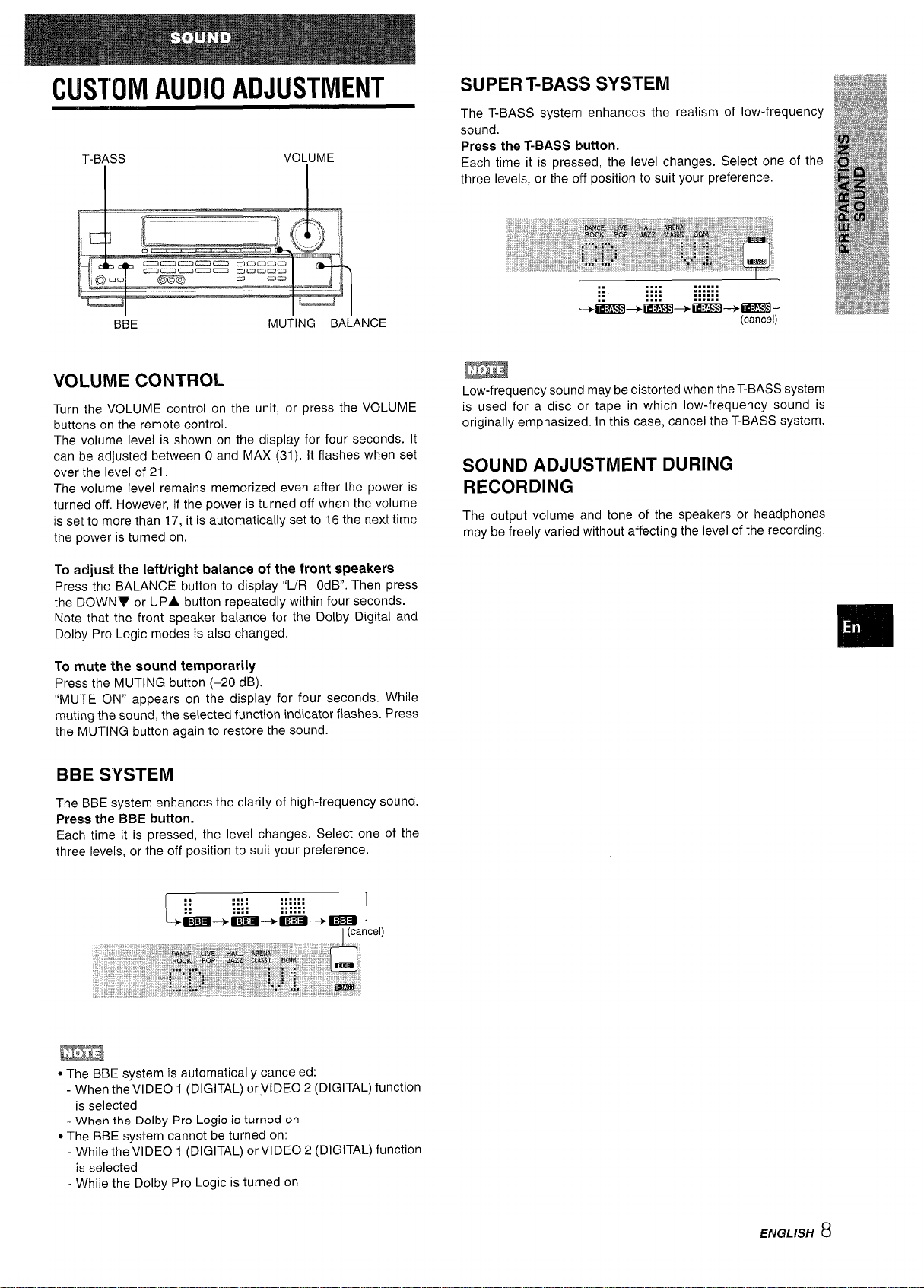
CUSTOM AUDIO ADJUSTMENT
BBE
MUTING BALANCE
SUPER T-BASS SYSTEM
The T-BASS system enhances the realism of low-frequency
sound.
Press the T-BASS button.
Each time it is pressed, the level changes. Select one of the
three levels, or the off position to suit your preference.
.... ......
::
::
I
+aj!m+tE?iE3+mm3 -+cams
.... ......
.... ......
.... ......
-1
(cancel)
VOLUME CONTROL
Turn the VOLUME control on the unit, or press the VOLUME
buttons on the remote control.
The volume level is shown on the display for four seconds. It
can be adjusted between O and MAX (31). It flashes when set
over the level of 21.
The volume level remains memorized even after the power is
turned off. However, if the power is turned off when the volume
is set to more than 17, it is automatically set to 16 the next time
the power is turned on.
To adjust the Ieft/right balance of the front speakers
Press the BALANCE button to display “L/R OdB. Then press
the DOWNV or UPA button repeatedly within four seconds.
Note that the front speaker balance for the Dolby Digital and
Dolby Pro Logic modes is also changed.
To mute the sound temporarily
Press the MUTING button (–20 dB).
“MUTE ON” appears on the display for four seconds. While
muting the sound, the selected function indicator flashes. Press
the MUTING button again to restore the sound.
BBE SYSTEM
The BBE system enhances the clarity of high-frequency sound.
Press the BBE button.
Each time it is pressed, the level changes. Select one of the
three levels, or the off position to suit your preference.
m
Low-frequency souncl maybe distorted when the T-BASS system
is used for a disc clr tape in which low-frequency sound is
originally emphasized. In this case, cancel the T-BASS system.
SOUND ADJUSTMENT DURING
RECORDING
The output volume and tone of the speakers or headphones
may be freely varied ‘without affecting the level of the recording.
.,,, ,,....
::
::
ma+i3El+EEl+ma
L
.... ......
.... ......
.... ......
J
I(cancel)
m
* The BBE system is automatically canceled:
- When the VIDEO 1 (DIGITAL) or VIDEO 2 (DIGITAL) function
is selected
- When the Dolby Pro Logic is turned on
~The BBE system cannot be turned on:
- While the VIDEO 1 (DIGITAL) or VIDEO 2 (DIGITAL) function
is selected
- While the Dolby Pro Logic is turned on
ENGLISH
8
Page 10
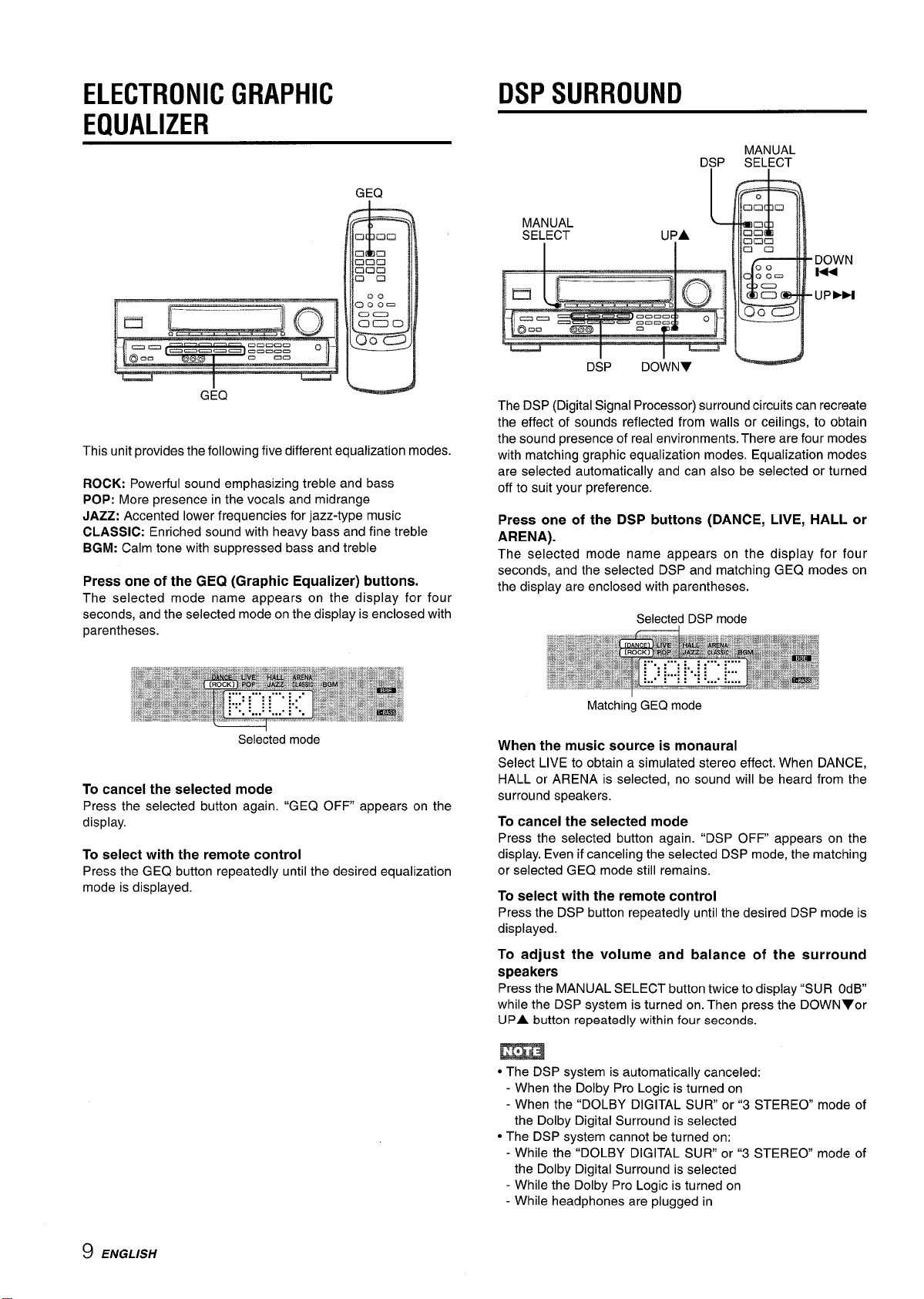
ELECTRONIC GRAPHIC
EQUALIZER
DSP SURROUND
GEQ
G:Q
This unit provides the following five different equalization modes.
ROCK: Powerful sound emphasizing treble and bass
POP: More presence in the vocals and midrange
JAZZ: Accented lower frequencies for jazz-type music
CLASSIC: Enriched sound with heavy bass and fine treble
BGM: Calm tone with suppressed bass and treble
Press one of the GEQ (Graphic Equalizer) buttons.
The selected mode name appears on the display for four
seconds, and the selected mode on the display is enclosed with
parentheses.
Selected mode
To cancel the selected mode
Press the selected button again. ‘iGEQ OFF appears on the
display.
To select with the remote control
Press the GEQ button repeatedly until the desired equalization
mode is displayed.
The DSP (Digital Signal Processor) surround circuits can recreate
the effect of sounds reflected from walls or ceilings, to obtain
the sound presence of real environments. There are four modes
with matching graphic equalization modes. Equalization modes
are selected automatically and can also be selected or turned
off to suit your preference.
Press one of the DSP buttons (DANCE, LIVE, HALL or
ARENA).
The selected mode name appears on the display for four
seconds, and the selected DSP and matching GEQ modes on
the display are enclosed with parentheses.
Selected DSP mode
Matching GEQ mode
When the music source is monaural
Select LIVE to obtain a simulated stereo effect. When DANCE,
HALL or ARENA is selected, no sound will be heard from the
surround speakers.
To cancel the selected mode
Press the selected button again. “DSP OFF appears on the
display. Even if canceling the selected DSP mode, the matching
or selected GEQ mode still remains.
To select with the remote control
Press the DSP button repeatedly until the desired DSP mode is
displayed.
9 ENGLISH
To adjust the volume and balance of the surround
speakers
Press the MANUAL SELECT button twice to display “SUR OdB
while the DSP system is turned on. Then press the DOWNYor
UPA button repeatedly within four seconds.
m
● The DSP system is automatically canceled:
- When the Dolby Pro Logic is turned on
- When the “DOLBY DIGITAL SUR or”3 STEREO mode of
the Dolby Digital Surround is selected
● The DSP system cannot be turned on:
- While the “DOLBY DIGITAL SLJR” or “3 STEREO” mode of
the Dolby Digital Surround is selected
- While the Dolby Pro Logic is turned on
- While headphones are plugged in
Page 11
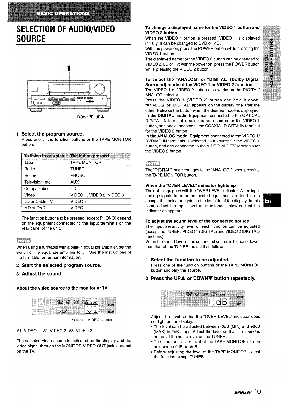
SELECTION OF AUDIO/VIDEO
SOURCE
1
DOWNY, UPA
1
Select the program source.
Press one of the function buttons or the TAPE MONITOR
button.
To change a displayed name for the VIDEO 1 button
and
VIDEO 2 button
When the VIDEO 1 button is pressed, VIDEO 1 is displayed
initially. It can be changed to DVD or MD.
With the power on, press the POWER button while pressing the
VIDEO 1 button.
The displayed name for the VIDEO 2 button can be changeld to
VIDEO 2, LD or TV; with the power on, press the POWER buitton
while pressing the VIDEO 2 button.
To select the “ANALOG” or “DIGITAL” (Dolby Digital
Surround) mode of the VIDEO 1 or VIDEO 2 function
The VIDEO 1 or VIDEO 2 button also works as the DIGITAU
ANALOG selector.
Press the VIDEO ‘1 (VIDEO 2) button and hold it down.
“ANALOG” or “DIGI1-AL” appears on the display one after the
other. Release the button when the desired mode is displayed.
In the DIGITAL modle: Equipment connected to the OPTICAL
DIGITAL IN terminal is selected as a source for the VIDEO 1
button, and one connected to the COAXIAL DIGITAL IN terminal
for the VIDEO 2 button.
In the ANALOG mode: Equipment connected to the VIDEO 1/
DVD/MD IN terminals is selected as a source for the VIDEO 1
button, and one connected to the VIDEO 2/LD/TV terminals for
the VIDEO 2 button.
Radio TUNER
Record PHONO
Television, etc. AUX
I Compact disc I CD
Video VIDEO 1, VIDEO 2, VIDEO 3
LD or Cable TV VIDEO 2
MD or DVD VIDEO 1
The function buttons to be pressed (except PHONO) depend
on the equipment connected to the input terminals on the
rear panel of the unit.
ma
When using a turntable with a built-in equalizer amplifier, set the
switch of the equalizer amplifier to off. See the instructions of
the turntable for further information.
2 Start the selected program source.
3 Adjust the sound.
About the
video source to the monitor or TV
m
The “DIGITAL” mode changes to the “ANALOG, ” when pressing
the TAPE MONITOR button.
When the “OVER L.EVEL” indicator lights up
I
The unit is equipped with the OVER LEVEL indicator. When input
analog signals from the connected equipment are too high to
accept, the indicator lights on the left side of the display. In this
case, adjust the input level as mentioned below so that the
indicator disappears,
To adjust the sound level of the connected source
The input sensitivity level of each function can be adjusted
(excepttheTUNER,
functions),
When the sound level of the connected source is higher or lower
than that of the TUNIER, adjust it as follows.
1
Select the function to be adjusted.
Press one of the function buttons or the TAPE MONITOR
button and play the source.
2
Press the UPA or DOWNY button repeatedly
VIDEO 1 (DIGITAL) and VIDEO 2 (DIGITAL)
Selected VIDEO source
Vi: VIDEO 1, V2: VIDEO 2, V3: VIDEO 3
The selected video source is indicated on the display and the
video signal through the MONITOR VIDEO OUT jack is output
on the TV.
Adjust the level so that the “OVER LEVEL” indicator does
not light on the display.
● The level can be adjusted between -6d B (M IN) and +i8dB
(MAX) in 2dB steps. Adjust the level so that the sound is
output at the same level as the TUNER.
● The input sensitivity level of the TAPE MONITOR can be
adjusted to OdB or -6dB.
* Before adjusting the level of the TAPE MONITOR, select
the function except TUNER.
ENGL/SH
10
Page 12
TO PLAY A DVD OR LD RECORDED IN
DOLBY DIGITAL SURROUND
This receiver is equipped with the Dolby Digital decoder and
has the DIGITAL IN (both OPTICAL and COAXIAL) terminals.
When a DVD or LD player is connected to the DIGITAL IN terminal
of the receiver, you can enjoy theater-quality audio right in your
home when playing discs recorded in Dolby Digital Surround.
Before operation
Check that the TAPE MONITOR is not selected. If the TAPE
MONITOR is selected, press the TAPE MONITOR button so that
“TAPE OFF appears on the display.
12Press the VIDEO 1 (VIDEO 2) button and hold it
down until “DIGITAL” is displayed.
The DVD (LD) player connected to the OPTICAL (COAXIAL)
DIGITAL IN terminal is selected as a source.
Start playing the DVD (LD) recorded in Dolby
Digital Surround.
The “DOLBY DIGITAL” indicator will light on the left side of
the display when the bit stream of the Dolby Digital Surround
comes in the unit.
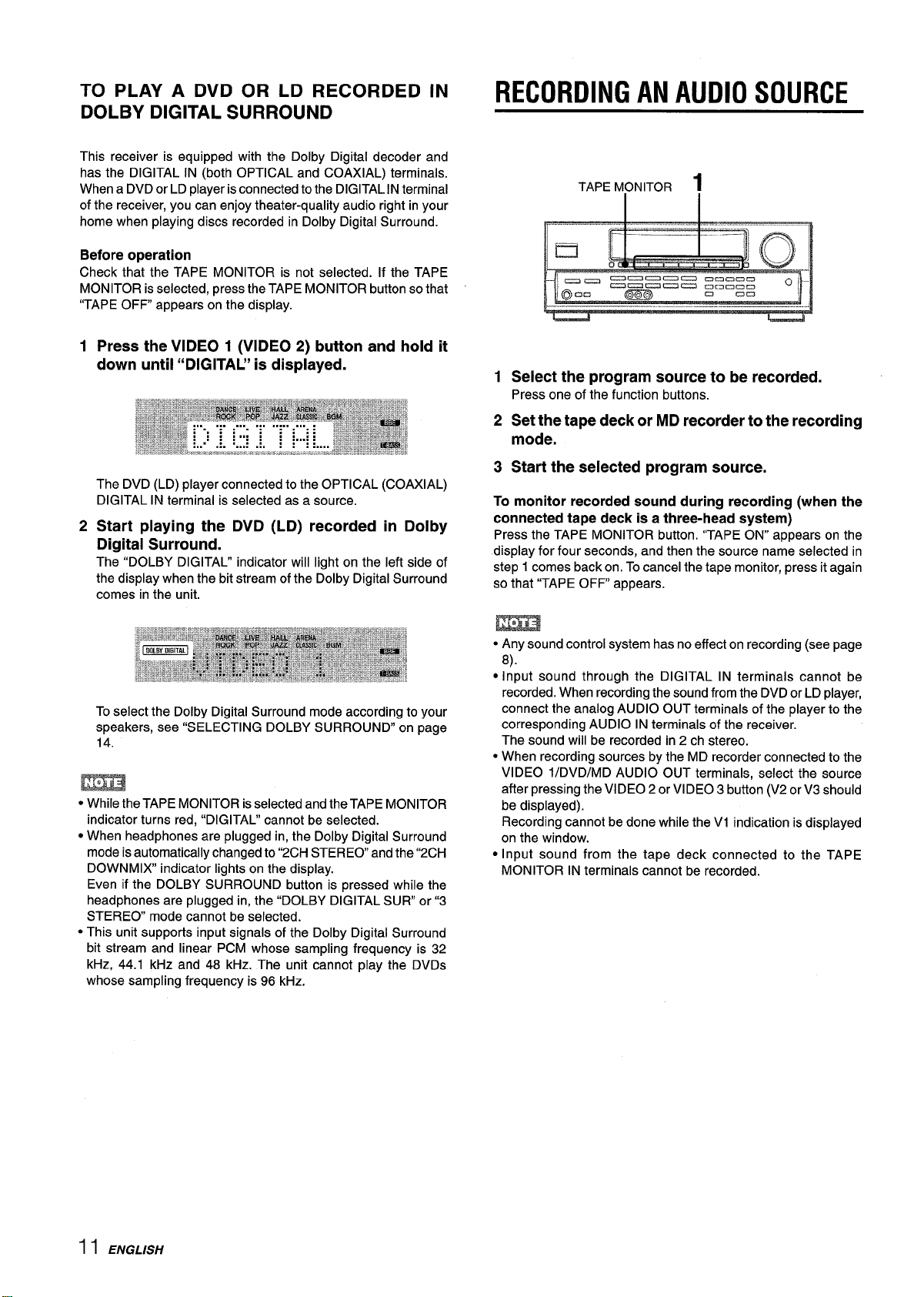
RECORDING AN AUDIO SOURCE
TAPE MONITOR
1
Select the program source to be recorded.
Press one of the function buttons.
2
Set the tape deck or MD recorder to the recording
mode.
3
Start the selected program source.
To monitor recorded sound during recording
connected tape
Press the TAPE MONITOR button. “TAPE ON” appears on the
display for four seconds, and then the source name selected in
step 1 comes back on. To cancel the tape monitor, press it again
so that “TAPE OFF appears.
deck is a three-head system)
1
(when the
To select the Dolby Digital Surround mode according to your
speakers, see “SELECTING DOLBY SURROUND” on page
14.
m
● While the TAPE MONITOR is selected and the TAPE MONITOR
indicator turns red, “DIGITAL” cannot be selected.
● When headphones are plugged in, the Dolby Digital Surround
mode is automatically changed to “2CH STEREO and the “2CH
DOWNMIX indicator lights on the display.
Even if the DOLBY SURROUND button is pressed while the
headphones are plugged in, the “DOLBY DIGITAL SUR” or”3
STEREO mode cannot be selected.
● This unit supports input signals of the Dolby Digital Surround
bit stream and linear PCM whose sampling frequency is 32
kHz, 44.1 kHz and 48 kHz. The unit cannot play the DVDS
whose sampling frequency is 96 kHz.
● Any sound control system has no effect on recording (see page
8).
● Input sound through the DIGITAL IN terminals cannot be
recorded. When recording the sound from the DVD or LD player,
connect the analog AUDIO OUT terminals of the player to the
corresponding AUDIO IN terminals of the receiver.
The sound will be recorded in 2 ch stereo.
● When recording sources by the MD recorder connected to the
VIDEO l/DVD/MD AUDIO OUT terminals, select the source
after pressing the VIDEO 2 or VIDEO 3 button (V2 or V3 should
be displayed).
Recording cannot be done while the VI indication is displayed
on the window.
● Input sound from the tape deck connected to the TAPE
MONITOR IN terminals cannot be recorded.
11 ENGLISH
Page 13
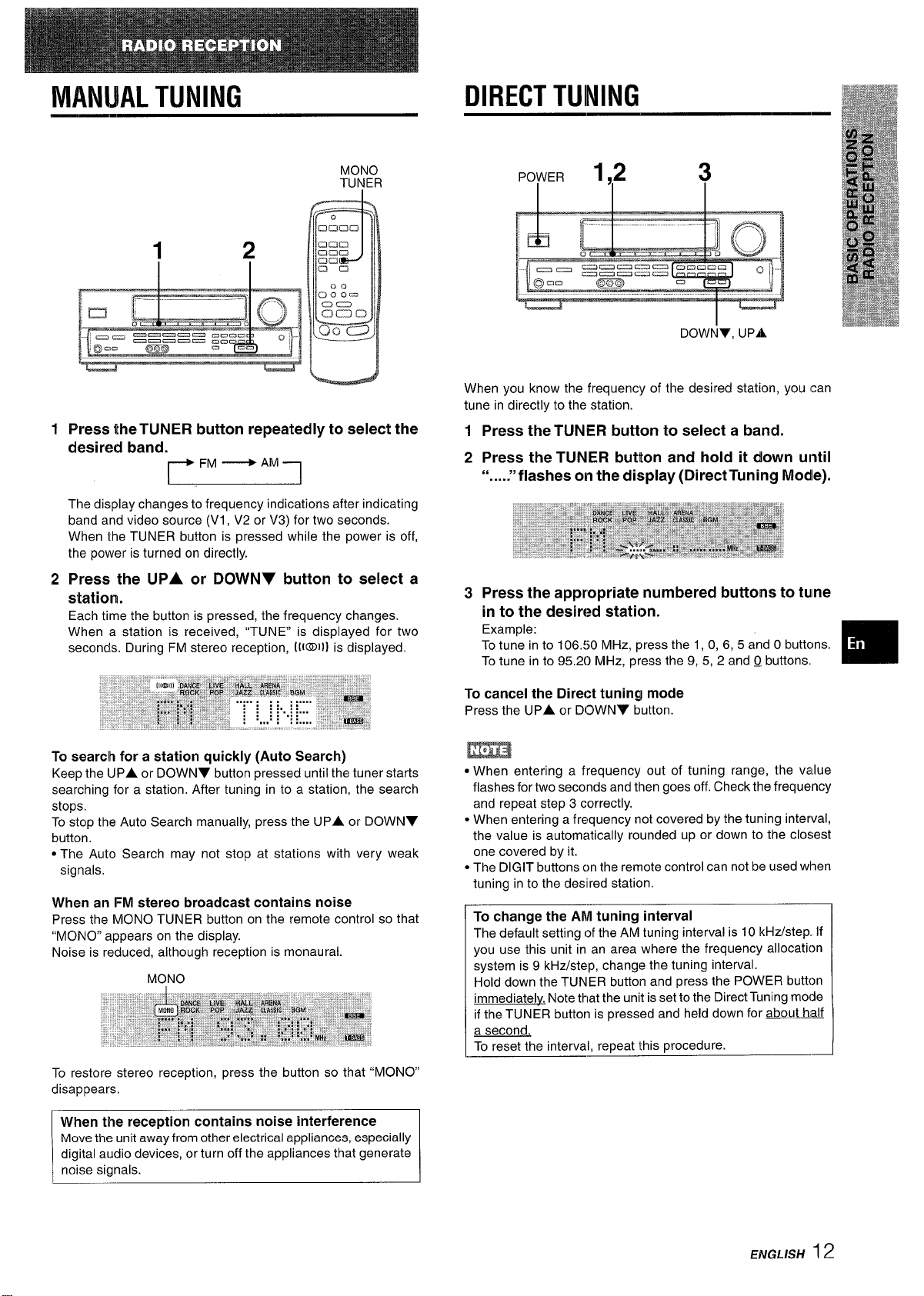
MANUAL TUNING
DIRECT TUNING
MONO
TUNER
1
Press the TUNER button repeatedly to select the
desired band.
~FM~AM-1
I
The display changes to frequency indications after indicating
band and video source (VI, V2 or V3) for two seconds.
When the TUNER button is pressed while the power is off,
the power is turned on directly.
2
Press the UPA or DOWNY button to select a
I
station.
Each time the button is pressed, the frequency changes.
When a station is received, “TUNE” is displayed for two
seconds. During FM stereo reception, [i@Ill is displayed.
POWER
1,2
3
DOWNY, UPA
When you know the frequency of the desired station, you can
tune in directly to the station.
1 Press the TUNER button to select a band.
2 Press the TUNER button and hold it down until
“
“flashes
011 the display (Direct Tuning Modle)......
3 Press the appropriate numbered buttons to tume
in to the desired station.
Example:
To tune in to 106,50 MHz, press the 1, 0, 6, 5 and O buttcms.
To tune in to 95.20 MHz, press the 9, 5, 2 and Q buttons.
m
To search for a station quickly (Auto Search)
Keep the UPA or DOWNY button pressed until the tuner starts
searching for a station. After tuning in to a station, the search
stops.
To stop the Auto Search manually, press the
button.
● The Auto Search may not stop at stations with very weak
signals.
UPA or DOWNY
When an FM stereo broadcast contains noise
Press the MONO TUNER button on the remote control so that
“MONO” appears on the display.
Noise is reduced, although reception is monaural.
MONO
To restore stereo reception, press the button so that “MONO”
disappears.
When the reception contains noise interference
Move the unit away from other electrical appliances, especially
digital audio devices, or turn off the appliances that generate
noise signals.
To cancel the Direct tuning mode
Press the UPA or DOWNV button.
● When entering a frequency out of tuning range, the value
flashes for two seconds and then goes off. Check the frequency
and repeat step 3 correctly.
● When entering a frequency not covered by the tuning interval,
the value is automatically rounded up or down to the closest
one covered by it.
● The DIGIT buttons cm the remote control can not be l~sed when
tuning in to the desllred station.
To change the AM tuning interval
The default setting of the AM tuning interval is
you use this unit in an area where the frequency allocation
system is 9 kHz/step, change the tuning interval.
Hold down the TUNER button and press the POWER button
immediately. Note that the unit is set to the Direct Tuning mode
if the TUNER button is pressed and held down for about haLf
a second.
To reset the interval, repeat this procedure.
10 kHz/step If
ENGLISH 12
Page 14
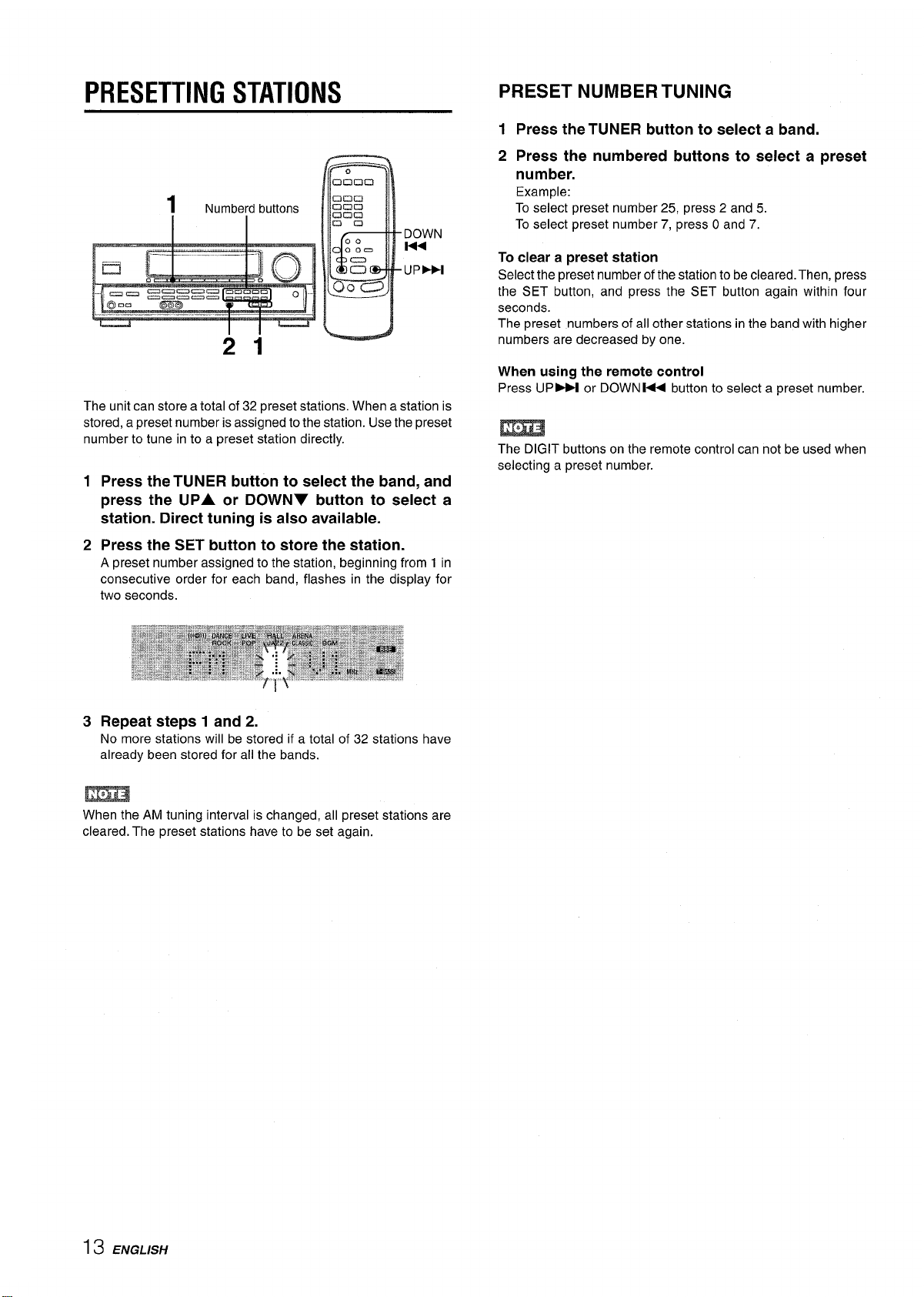
PRESETTING STATIONS
)
21
The unit can store a total of 32 preset stations. When a station is
stored, a preset number is assigned to the station. Use the preset
number to tune in to a preset station directly.
1
Press the TUNER button to select the band, and
press the UPA or DOWN7 button to select a
station. Direct tuning is also available.
PRESET NUMBER TUNING
1 Press the TUNER button to select a band.
2 Press the numbered buttons to select a preset
number.
Example:
To select preset number 25, press 2 and 5.
To select preset number 7, press O and 7.
To clear a preset station
Select the preset number of
the SET button, and press the
seconds.
The preset numbers of all other stations in the band with higher
numbers are decreased by one.
When using the remote control
Press UP M or DOWN W button to select a preset number.
The DIGIT buttons on the remote control can not be used when
selecting a preset number.
the stationto be cleared. Then, press
SET button again within four
Press the SET button to store the station.
2
A preset number assigned to the station, beginning from 1 in
consecutive order for each band, flashes in the display for
two seconds.
Repeat steps 1 and 2.
3
No more stations will be stored if a total of 32 stations have
already been stored for all the bands.
m
When the AM tuning interval is changed, all preset stations are
cleared. The preset stations have to be set again.
13 ENGLISH
Page 15
This unit is equipped with not only the Dolby Pro Logic decoder
but also Dolby Digital decoder.
The unit and the center and surround speakers (standard) assure
full-scale home theater sound. When playing back discs or video
software that have been recorded in Dolby Pro Logic or Dolby
Digital Surround, astonishingly realistic sound surrounds the
listener to create a new level of audio/visual entertainment.
Independent control of the five channels allows the listener to
enjoy the same type of sound reproduction experienced in movie
theaters. Voices are reproduced in the front and center sound
field, while ambient sounds like cars and crowds are reproduced
on all sides of the listener for an incredibly lifelike audio/video
experience. Please read the following carefully to “tune” the
system’s output to match the characteristics of your listening
space.
Check the following:
● Before enjoying the DOLBY SURROUND sound, adjust the
speaker sound levels to the proper balance (see page 15).
● Make sure the speakers are properly connected and positioned
(see pages 4 and 5).
● Make sure the TV set and video unit are properly connected
(see page 3).
● Make sure the disc and video tape, etc., support Dolby Pro
Logic or Dolby Digital Surround.
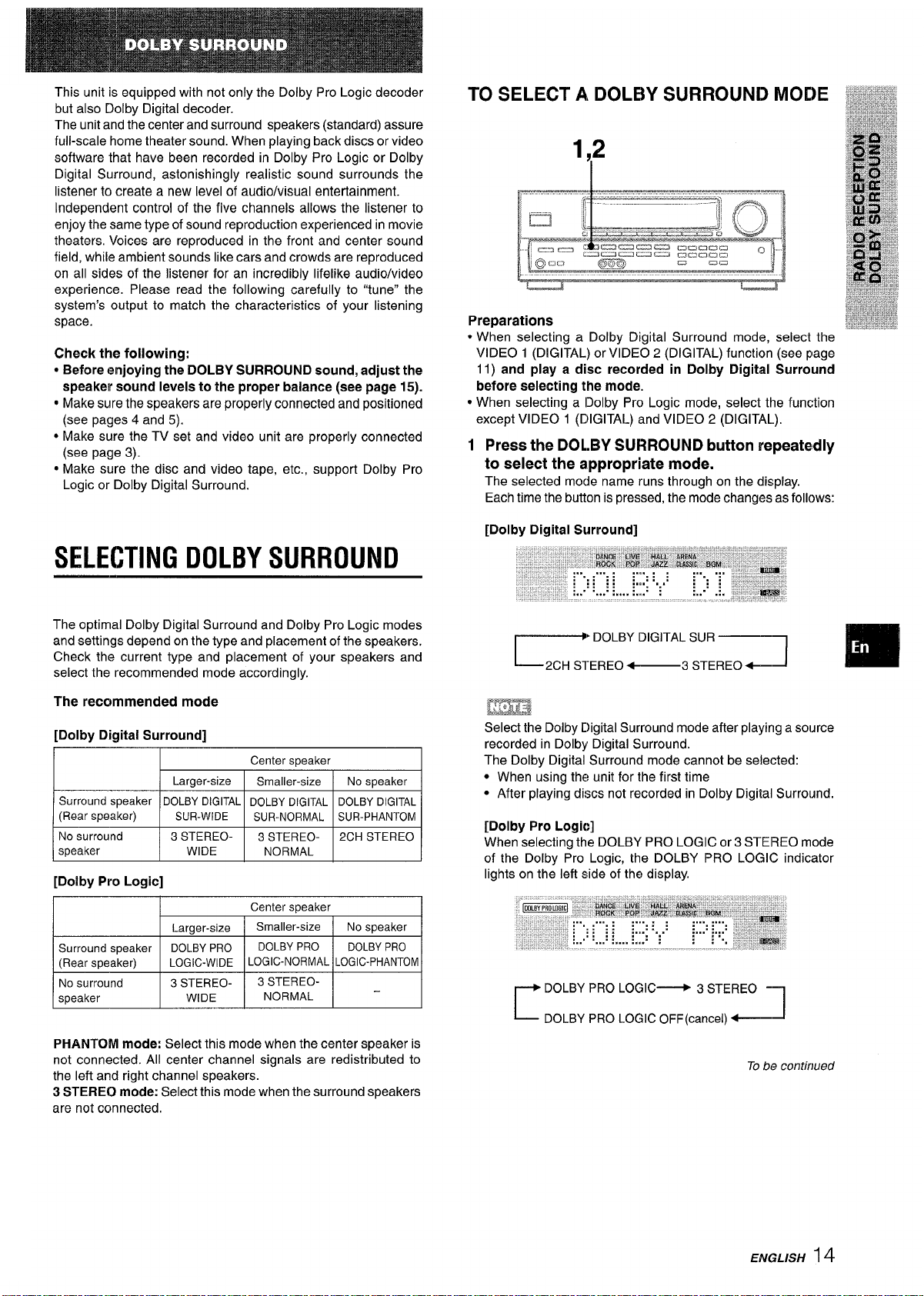
TO SELECT A, DOLBY SURROUND MODE
1,2
Preparations
*
When selecting a Dolby Digital Surround mode, select the
VIDEO 1 (DIGITAL) or VIDEO 2 (DIGITAL) function (see page
11) and play
before selecting the mode.
● When selecting a lDolby Pro Logic mode, select the function
except VIDEO 1 (DIGITAL) and VIDEO 2 (DIGITAL).
1 Press the DOLBY SURROUND button repeatedly
to select the appropriate mode.
The selected mode name runs through on the display.
Each time the button is pressed, the mode changes as follows:
[Dolby Digital Surround]
a disc recorded in Dolby Digital Surround
SELECTING DOLBY SURROUND
The optimal Dolby Digital Surround and Dolby Pro Logic modes
and settings depend on the type and placement of the speakers.
Check the current type and placement of your speakers and
select the recommended mode accordingly.
The recommended mode
[Dolby Digital Surround]
I
/ Lamer-size I Srnalier-size I NOs~eaker I
Surround speaker DOLBY DIGITAL DOLBY DIGITAL DOLBYDIGITAL
(Rear speaker)
No surround
speaker WIDE
SUR-WIDE
I
3 STEREO- 3 STEREO-
[Dolby Pro Logic]
I
LOGIC-WIDE LOGIC-NORMAL LOGIC-PHANTOM
~
Center s~eaker
SUR-NORMAL SUR-PHANTOM
I I
NORMAL
Center speaker
2CH STEREO
* DOLBY DIGITAL SUR
2CH STEREO ~
,STEREO+-]
❑
Lmm
Select the Dolby Digital Surround mode after playing a source
recorded in Dolby Digital Surround.
I
I
The Dolby Digital Surround mode cannot be selected:
● When using the unit for the first time
● After playing discs not recorded in Dolby Digital Surround.
[Dolby Pro Logic]
When selecting the DOLBY PRO LOGIC or 3 STEREO mode
of the Dolby Pro Logic, the DOLBY PRO LOGIC indicator
lights on the left side of the display.
DOLBY PRO LOGIC~ 3 STEREO -
1-
~ DOLBY PRO LOGIC OFF(cancel) ~J
1
PHANTOM mode: Select this mode when the center speaker is
not connected. All center channel signals are redistributed to
the left and right channel speakers.
3 STEREO mode:
are not connected.
Select this mode when the surround speakers
To be contirwed
ENGLISH 14
Page 16
2 Press the DOLBY SURROUND button again and
hold it down until the center speaker mode to be
selected appears.
When selecting the DOLBY DIGITAL SUR or DOLBY PRO
LOGIC mode in step 1:
“NORMAL;
When selecting the 3 STEREO mode
“NORMAL’ and “WIDE appear one after the other.
● Depending on the sound source or listening condition, surround
effect may not be obtained even when the Dolby Digital
Surround or Dolby Pro Logic is selected.
● The full Dolby Digital Surround or Dolby Pro Logic effect cannot
be obtained when using software not recorded in the Dolby
Digital Surround or Dolby Pro Logic system. In this case, use
the DSP surround system instead (see page 9).
● When headphones are plugged in:
- The Dolby Pro Logic system is automatically canceled.
- The Dolby Digital Surround mode is automatically changed
to “2CH STEREO.”
● While headphones are plugged in:
- The Dolby Pro Logic cannot be turned on.
- The “DOLBY DIGITAL SUR” or “3 STEREO mode of the
Dolby Digital Surround cannot be selected.
“WIDE and “PHANTOM” appear in turn.
in step 1:
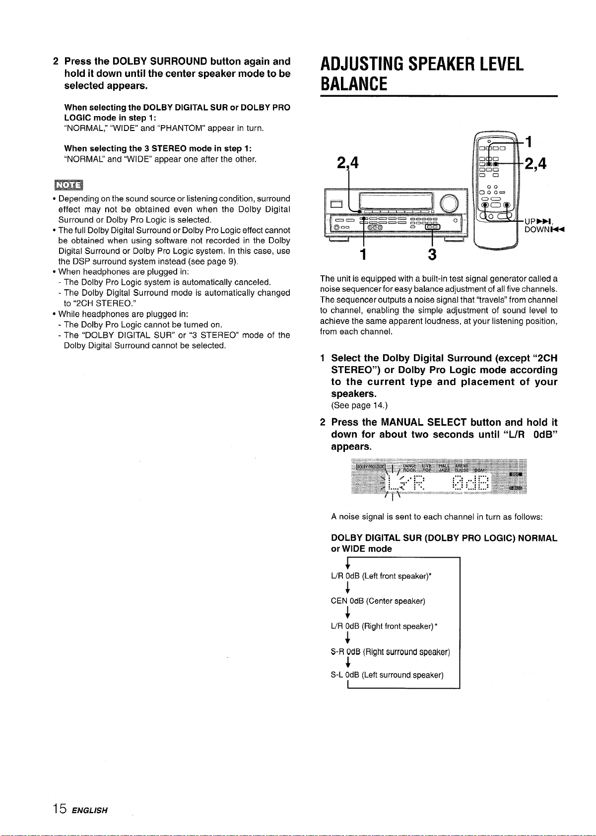
ADJUSTING SPEAKER LEVEL
BALANCE
1
214
1
The unit is equipped with a built-in test signal generator called a
noise sequencer for easy balance adjustment of all five channels.
The sequencer outputs a noise signal that “travels” from channel
to channel, enabling the simple adjustment of sound level to
achieve the same apparent loudness, at your listening position,
from each channel.
1
Select the Dolby Digital Surround (except “2CH
STEREO”) or Dolby Pro Logic mode according
to the current type and placement of your
speakers.
(See page 14.)
3
2,4
“UPPM,
DOWNM
2
Press the MANUAL SELECT button and hold it
down for about two seconds until “L/R OdB”
appears.
A noise signal is sent to each channel in turn as follows:
DOLBY DIGITAL SUR (DOLBY PRO LOGIC) NORMAL
or WIDE mode
+
L/R OdB (Left front speaker)*
CEN OdB(Center speaker)
UR ~dB (Right front speaker)*
*
S-R OdB (Right surround speaker)
$
S-L OdB (Left surround speaker)
I
15 ENGLISH
Page 17
—...—.-. —. —..—
——.
DOLBY DIGITAL SUR (DOLBY PRO LOGIC) PHANTOM
mode
L/R OdB*+ L/R OdB’
r
S-L OdB~S-R OdB
J
DOLBY DIGITAL SUR (DOLBY PRO LOGIC) 3 STEREO
NORMAL or WIDE mode
~ UR OdB’+CE
‘ “L” or “R” flashes to indicate one of the front speakers from
which the noise signal is output,
3
Adjust the sound level of the center and surround
N OdB+ UR OdB*
1
speakers.
While “CEN, ” ‘(S-P’ or “S-R flashes in the display, press the
UPA or DOWN7 button so that the sound level of the center
or surround speakers matches that of the front speakers,
The balance of the front speakers can be adjusted as well
while
“L/R is displayed.
4
Press the MANUAL SELECT button again to stop
the noise signal.
m
● The UPMM or DOWN 14< button on the remote control cannot
be used in step
noise signals.
* When adjusting the speaker level balance of the Dolby Digital
Surround, that of the Dolby Pro Logic is also changed and vice
versa.
About the channels
The left and right speakers create the stereo effect.
The center speaker helps achieve precise sound positioning
over a broad sound field,
The rear-mounted surround speakers enhance the “depth” of
the sound field,
3 when adjusting the speaker balance with the
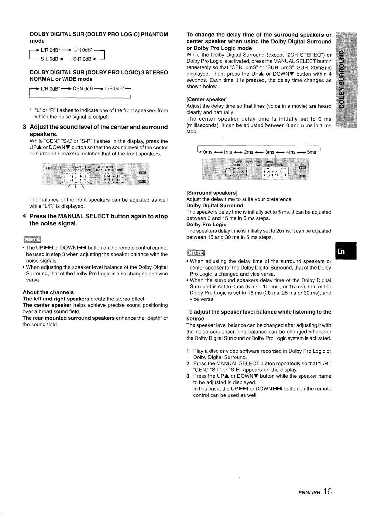
To change the delay time of the surround speakers or
center speaker when using the Dolby Digital Surround
or Dolby Pro Logic mode
While the Dolby Digital Surround (except “2CH STEREO”) or #
Dolby Pro Logic is activated, press the MANUAL SELE:CT button
repeatedly so that “CEN OmS” or “SUR 5mS” (SUR 20mS) is
displayed. Then, press the UPA or DOWN7 button withlln 4
seconds. Each time it is pressed, the delay time changes as
shown below.
[Center speaker]
Adjust the delay time so that lines
clearly and naturally,
The center speaker delay time is initially set to O ms
(milliseconds). It can be adjusted between Oand 5 rns in 1 ms
step.
LOms ++1 ms ++ 2ms _ 3ms _ 4ms _ 5ms J
(voice in a movie) are heard
[Surround speakers]
Adjust the delay time to suite your preference,
Dolby Digital Surround
The speakers delay time is initially set to 5 ms. It can be adjusted
between O and 15 ms in 5 ms steps.
Dolby Pro Logic
The speakers delay time is initially set to 20 ms. It can be adjusted
between 15 and 30 ms in 5 ms stetx.
m
● When adjusting the delay time of the surround speakers or
center speaker for Ihe Dolby Digital Surround, that of the Dolby
Pro Logic is changed and vice versa.
● When the surround speakers delay time of the Dolby Digital
Surround is set to (0 ms (5 ms, 10 ms , or 15 ins), that of the
Dolby Pro Logic is set to 15 ms (20 ms, 25 ms or 30 ins), and
vice versa,
To adjust the speaker level balance while listening to the
source
The speaker level balance can be changed after adjusting itwith
the noise sequencer. The balance can be changed whenever
the Dolby Digital Surround or Dolby Pro Logic system is activated,
D
,,,,
❑
1
Play a disc or video software recorded in Dolby Pro Logic or
Dolby Digital Surround.
Press the MANUAL SELECT button repeatedly so that “l./R,”
2
“CEN; “S-U or “S-R” appears on the display.
Press the UPA c)r DOWNY button while the speaker name
3
to be adjusted is displayed.
In this case, the lJP-I or DOWNW< button on the remote
control can be used as well.
ENGLISH 161
Page 18
ADJUSTING DOLBY DIGITAL
SURROUND SOUND
MANUAL
SEL/Z2T
ADJUSTING DYNAMIC RANGE
Dynamic range of the Dolby Digital Surround sound can be
adjusted. The unit is initially set to the “STD” (standard) mode.
1 While the Dolby Digital Surround is activated,
press the SET button and hold it down until “MID
NIGHT THEATER” runs through on the display.
DOWN
UP-
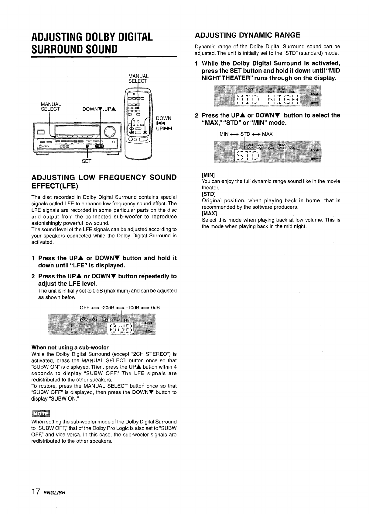
ADJUSTING LOW FREQUENCY SOUND
EFFECT(LFE)
The disc recorded in Dolby Digital Surround contains special
signals called LFE to enhance low frequency sound effect. The
LFE signals are recorded in some particular parts on the disc
and output from the connected sub-woofer to reproduce
astonishingly powerful low sound.
The sound level of the LFE signals can be adjusted according to
your speakers connected while the Dolby Digital Surround is
activated.
Press the
1
down until “LFE” is displayed.
Press the UPA or DOWNY button repeatedly to
2
adjust the LFE level.
The unit is initially set to OdB (maximum) and can be adjusted
as shown below.
UPA or DOWNT button and hold it
2 Press the UPA or DOWNY button to select the
“MAX;’ “STD” or “MIN” mode.
MIN _ STD ~ MAX
[MIN]
Youcan enjoy the full dynamic range sound like in the movie
theater,
[STD]
Original position, when playing back in home, that is
recommended by the software producers.
[MAX]
Select this mode when playing back at low volume. This is
the mode when playing back in the mid night.
OFF _ -20dB _ -lOdB _
When not using a sub-woofer
While the Dolby Digital Surround (except “2CH STEREO”) is
activated, press the MANUAL SELECT button once so that
“SUBW ON” is displayed. Then, press the
seconds to display “SUBW OF F.” The LFE signals are
redistributed to the other speakers.
To restore, press the MANUAL SELECT button once so that
“SUBW OFF is displayed, then press the DOWNV button to
display “SUBW ON.”
m
When setting the sub-woofer mode of the Dolby Digital Surround
to “SUBW OFF: that of the Dolby Pro Logic is also set to “SUBW
OFF: and vice versa. In this case, the sub-woofer signals are
redistributed to the other speakers.
UPA button within 4
OdB
17 ENGLISH
Page 19
OPERATING TV, CABLE TV, VCR
AND CD PLAYER
You can control basic functions of a TV, CABLE TV, VCR and
CD player with this remote control.
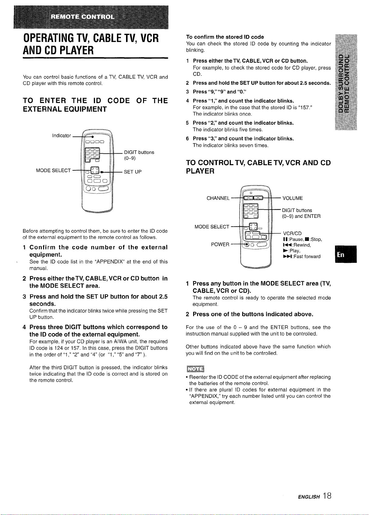
TO ENTER THE ID CODE OF THE
EXTERNAL EQUIPMENT
Indicator
DIGIT buttons
(o-9)
MODE SELECT
SET UP
To confirm the stored ID code
You can check the stored ID code by counting the indicator
blinking.
Press either thelW, CABLE, VCR or CD button.
1
For example, to check the stored code for CD player, press
CD.
Press and hold the SET UP button for about 2.5 seconds.
2
Press “9/’ “9” and “O.”
3
Press “1;’ and count the indicator blinks.
4
For example, in the case that the stored ID is “157.”
The indicator blinks once.
Press “2;’ and count the indicator blinks.
5
The indicator blinks five times,
Press “3;’ and count the indicator blinks.
6
The indicator blinks seven times,
TO CONTROL TV, CABLE TV, VCR AND CD
PLAYER
VOLUME
DIGIT buttons
(O-9) and ENTER
Before attempting to control them, be sure to enter the ID code
of the external equipment to the remote control as follows.
Confirm the code number of the external
1
equipment.
See
the ID code list in the “APPENDIX’ at the end of this
manual,
Press either the TV, CABLE, VCR or CD button in
2
the MODE SELECT area.
Press and hold the SET UP button for about 2.5
3
seconds.
Confirm that the indicator blinks twice while pressing the SET
UP button.
4
Press three DIGIT buttons which correspond to
the ID code of the external equipment.
For example, if your CD player is an AIWA unit, the required
ID code is 124 or 157. In this case, press the DIGIT buttons
in the order of”1 ,“ “2 and “4” (or “1 ,“ “5” and “7” ).
After the third DIGIT button is pressed, the indicator blinks
twice indicating that the ID code is correct and is stored on
the remote control.
MODE SELECT -
VCRICD
POWER -
Press any button in the MODE SELECT area (TV,
1
lfl:Pause, U: Stop,
M: Rewind,
-: Play,
W :Fast forward
CABLE, VCR or CD).
The remote control is ready to operate the selected mode
equipment.
2
Press one of the buttons indicated above.
For the use of the O – 9 and the ENTER buttons, see the
instruction manual supplied with the unit to be controlled.
Other buttons indicated above have the same function which
you will find on the unit to be controlled.
● Reenter the ID CODE of the external equipment after replacing
the batteries of the remote control.
● [f there are plural ID codes for external equipment in the
“APPENDIX,” try each number listed until you can control the
external equipment.
❑
ENGLISH 18
Page 20
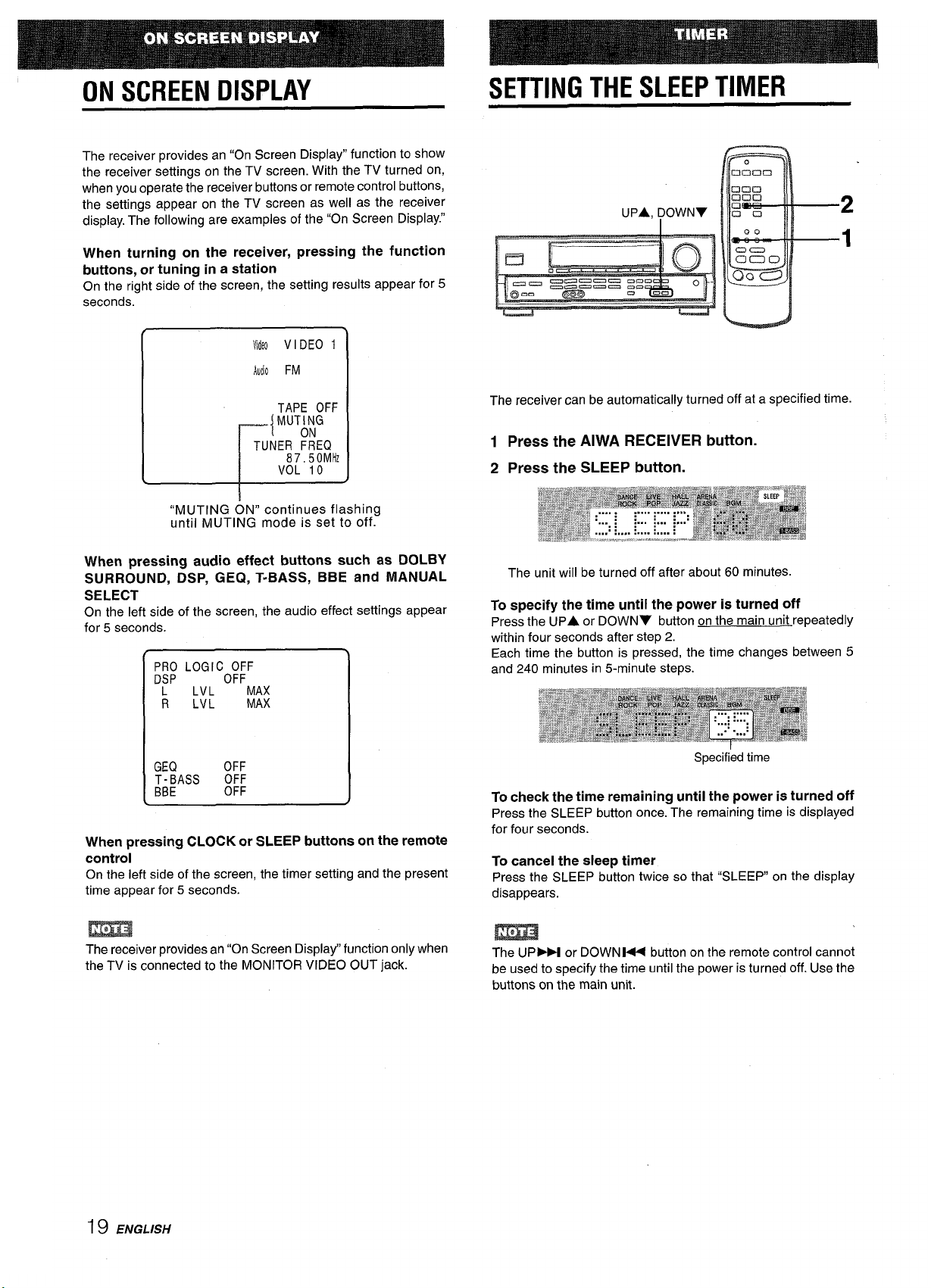
ON SCREEN DISPLAY
SETTING THE SLEEP TIMER
The receiver provides an “On
the receiver settings on the TV screen. With the TV turned on,
when you operate the receiver buttons or remote control buttons,
the settings appear on the TV screen as well as the receiver
display. The following are examples of the “On Screen Display.”
Screen Display” function to show
When turning on the receiver, pressing the function
buttons, or tuning in a station
On the right side of the screen, the setting results appear for 5
MdN VIDEO 1
AUJOFM
TAPE OFF
MUT;;G
{
TUNER FREQ
87,50 MHz
VOL 10
L
“MUTING ON” continues flashing
until MUTING mode is set to off.
When m’essina audio effect buttons such as DOLBY
SURROUND, &P, GEQ, T-BASS, BBE and MANUAL
SELECT
On the left side of the screen, the audio effect settings appear
for 5 seconds.
PRO LOGICO:;F
DSP
L
LVL
R
LVL
MAX
MAX
UPA, ~OWN7
The receiver can be automatically turned off at a specified time.
1 Press the AIWA RECEIVER button.
2 Press the SLEEP button.
The unit will be turned off after about 60 minutes.
specify the time until the power is turned off
To
Press the UPA
within four seconds after step 2.
Each time the button is pressed, the time changes between 5
and 240 minutes in 5-minute steps.
or DOWNV button on the main unit repeatedly
2
1
GEQ OFF
T-BASS
BBE
When pressing CLOCK or SLEEP buttons on the remote
OFF
OFF
controi
On the left side of the screen, the timer setting and the present
time appear for 5 seconds.
The receiver provides an “On Screen Display” function only when
the TV is connected to the MONITOR VIDEO OUT jack.
Specified time
To check the time remaining until the power is turned off
Press the SLEEP button once. The remaining time is displayed
for four seconds.
To cancei the sleep timer
Press the SLEEP button twice so that “SLEEP on the display
disappears.
m
The UP- or DOWNW button on the remote control cannot
be used to specify the time until the power is turned off. Use the
buttons on the main unit.
19 ENGLISH
Page 21
CARE AND MAINTENANCE SPECIFICATIONS
Occasional care and maintenance of the unit is needed to
optimize the performance of your unit.
To clean the cabinet
Use a soft dry cloth.
If the surfaces are extremely dirty, use a soft cloth lightly
moistened with mild detergent solution. Do not use strong
solvents, such as alcohol, benzine or thinner as these could
damage the finish of the unit.
FM tuner section
Tuning range 87.5 MHz to 108 MHz
dBf
Usable sensitivity
13,2
(IHF)
ohms (unbalanced)
Antenna terminale
75
AM tuner section
kHz to 1710 kHz (1O kHz step),
Tuning range
Usable sensitivity
Antenna
530
531 kHz to 1602 kHz (9 kHz step)
pVlm
350
Loop antenna
Amplifier secltion
Power output
[Stereo
Front
130 watts per channel, Min. RMS
ohms, from 40 Hz to 20 kHz, with no
more than 0.97. Total Harmonic
Distortion
[Dolby Digital Surround olr Dolby
Pro Logic Mode]
Front
120 watts
ohms, from 40 Hz to 20 kHz, with no
more than 0.9°A Total Harmonic
Distortion
Rear (Surround)
60 watts per channel, Min. RMS at 8
ohms, 1 kHz, with no more than 0.9’%.
Total Harmonic Distortion
Center
120 watts, Min. RMS at 8 olhms, 1
kHz, with no more than 0.97. Total
Harmonic Distortion
Total harmonic 0.08 % (85 W, 1 kHz, 8 ohms, Front)
distortion
Inputs
AUDIO IN
DIGITAL IN
VIDEO IN: 1 Vp-p (75 ohms)
Mode]
per channel, Min. RMS at 8
PHONO: 2.5 mV, adjustable (47
kohms)
CD: 250 mV, adjustable (47
kohms)
TAPE MONITOR: 350 mV,
adjustable (47 kohms)
VIDEO l/DVD/MD, VIDEO 2/LD/
TV, VIDEO 3, AUX: 250 mV,
adjustable (47 kohms)
COAXIAL (VIDEO 2):
OPTICAL (VIDEO 1):
accept linear PCM (32 I(Hz, 44.1
kHz and 48 kHz) signals and bit
stream of Dolby Digital Surround
id 8
❑
To be continued
EldGrX/+20
Page 22
outputs
AUDIO OUT (REC OUT): 200 mV (1
kohm)
VIDEO OUT (MONITOR): 1 Vp-p (75
ohms)
SUPER WOOFER: 5.0 V
FRONT SPEAKERS IMP: 8Q/4Q
selectable (front speakers A and B):
with the SPEAKER IMPEDANCE
SELECTOR set to 4s2, accepts
speakers of 4 ohms.
with the SPEAKER IMPEDANCE
SELECTOR set to 8Q, accepts
speakers of 8 ohms or more.
SURROUND SPEAKERS IMP: 8Q
(surround speakers): accepts
speakers of 8 ohms or more
CENTER SPEAKER IMP: 8Q/4Q
selectable
with the SPEAKER IMPEDANCE
SELECTOR set to 4Q, accepts
speaker of 4 ohms.
with the SPEAKER IMPEDANCE
SELECTOR set to 8Q accepts
speaker of 8 ohms or more.
PHONES (stereo jack): accepts
headphones of 32 ohms or more
Muting
-20 dB
General
Power requirements 120 V AC, 60 Hz
Power consumption 230 W
Dimensions
(W XHXD)
Weight
430 x 155 x 351
(17 X6’/8 X137/8 in.)
11.2 kg (24 lb 11 OZ.)
Specifications and external appearance are subject to change
without notice.
mm
TROUBLESHOOTING GUIDE
If the unit fails to perform as described in these Operating
Instructions, check the following guide.
GENERAL
There is no sound.
● Is the AC cord connected properly?
● Is there an incorrect connection? (+ page 3, 4)
● There may be a short circuit in the speaker terminals.
+ Disconnect the AC cord, then correct the speaker
connections.
● Was an incorrect function button pressed?
● Are the FRONT SPEAKERS A and B buttons set correctly?
(+ page 7)
Sound is emitted from one speaker only.
● Is the BALANCE set appropriately?
● Is the other speaker disconnected?
Sound is heard at a very low volume.
● Has the MUTING button been pressed?
An erroneous display or a malfunction occurs.
Reset the unit as stated below.
+
TUNER SECTION
There is constant, wave-like static.
● Is the antenna connected properly? (+ page 5)
c Is the FM signal weak?
+ Connect an outdoor antenna.
The reception contains noise interference or the sound is
distorted.
● Is the system picking up external noise or multipath distortion?
+ Change the orientation of the antenna.
+ Move the unit away from other electrical appliances.
MESYSTEM
The word ‘iBBE and the “BBE symbol” are trademarks of BBE
Sound, Inc.
Under license from BBE sound, Inc.
Manufactured under license from Dolby Laboratories.
“Dolby”, “Pro Logic” and the double-D symbol are trademarks of
Dolby Laboratories. Confidential Unpublished Works. 019921997 Dolby Laboratories, Inc. All rights reserved.
To reset
If an unusual condition in the display window or malfunction
occurs, reset the unit as follows.
1 Press the POWER button to turn off the power.
2 Press the POWER button while pressing the SET button.
Everything stored in memory after purchase is canceled.
If the power cannot be turned off in step 1 because of a
malfunction, reset by disconnecting the AC cord and carry out
step 2,
21 ENGLISH
Page 23

PARTS INDEX
Instructions about each part ontheunit orremote control are
indicated on the pages listed below.
~a$habetical order)
Pages
AIWA RECEIVER
AUX
BALANCE
BBE
CD
CLOCK
DOLBY SURROUND
DOWN
V (1++)
DSP
FRONT SPEAKERS A, B
FUNCTION
GEQ
MANUAL SELECT (TEST)
MONO TUNER
MUTING, MUTE
PHONES
PHONO
POWER
RECEIVER/DIGIT
SET
SET UP
SLEEP
SPEAKER IMPEDANCE
SELECTOR
TAPE MONITOR
T-BASS
TUNER, BAND DIRECT
TUNER PRESET/SURROUND
uPA(PDi)
VIDEO 1
VIDEO 2
VIDEO 3
VOLUME (V,
A)
6,19
7,10
8
8
7,10
7
7114, 15
6,7,8,9, 10, 12, 13, 16, 17,
19
9
7
6
9
7,9,15,16
12
8
7
7,10
7,12
6
7,13,17
6,18
19
4
7,10,11
8
7, 10, 12, 13
6
6,7,8,9,10,12,13,16,17,
19
7,10,11
7,10,11
7, 10
8
ENGLISH
22!
Page 24

“PRECAUCION:PARA REDUCIR EL RIESGO
DE QUE SE PRODUZCAN SACUDIDAS
ELECTRICAS, NO QUITE LA CUBIERTA
(O PANEL POSTERIOR).
EN EL INTERIOR NO HAY PIEZAS QUE
DEBA REPARAR EL USUARIO.
SOLICITE LAS REPARACIONES
AL
PERSONAL DE SERVICIO CAPACITADO.”
PRECAUCIONES
Antes de utilizar la unidad, lea cuidadosa y completamente este
manual instrucciones. Guarde el manual de instrucciones para
futuras referencias. Todos Ios avisos y precauciones del manual
de instrucciones y de la unidad deberan seguirse estrictamente,
as[ como Ias sugerencias de seguridad indicadas a continuation.
Instalacion
1
Agua y humedad — No utilice esta unidad cerca del agua,
como al Iado de una bafiera, un Iavabo, una piscina, etc.
2
Calor — No utilice esta unidad cerca de fuentes termicas,
como salidas de calefaccion, estufas, ni demas aparatos que
generen calor.
Tampoco debera someterse a temperatures inferiors a 5°C
(41 ‘F) ni superiors a 35°C (95”F).
3
Superficie de montaje — Coloque la unidad sobre una
superficie plana y nivelada.
4
Ventilation — La unidad debera colocarse donde tenga
espacio suficiente a su alrededor para asegurar su ventilation
adecuada. Deje un espacio Iibre de 10 cm en la parte posterior
y superior de la unidad, y de 5 cm a cada Iado.
- No la coloque sobre unacama, una alfombra, ni nada similar
que pueda bloquear Ias aberturas de ventilation.
- No la instale en una Iibreria, un armario, ni un bastidor
cerrado, donde la ventilation podria ser deficient.
5
Entrada de objetos y Iiquidos —Tenga cuidado de que en
el interior de la unidad no entren objetos pequeiios ni Iiquidos
a traves de Ias aberturas de ventilation.
6
Carritos y estantes — Cuando haya colocado o montado la
unidad sobre un estante o un carrito,
debera moverla con cuidado.
Las paradas repentinas, la fuerza
excesiva, o Ias superficies desiguales
podr[an causar el vuelco o la cafda de la
combination de la unidad y el carrito.
7
Montaje en una pared o en el techo — La unidad no debera
montarse en una pared ni en el techo, a menos que se
especifique en el manual de instrucciones.
.L
A&*
3
m
Anotacion de[ propietario
Para su conveniencia, anote el ntimero de modelo y el numero
de serie (Ios encontrara en el panel trasero de su aparato) en el
espacio suministrado mas abajo. Mencionelos cuando se ponga
en contacto con su concesionario Aiwa en caso de tener
dificultades.
N,” de modelo
I AV-DV70
N.o de serie (N.O de Iote)
I
Eneraia electrica
1
Fuentes de alimentacion — Conecte esta unidad solamente
a Ias fuentes de alimentacion especificadas en Ias
instrucciones de manejo, y como esta marcado en la unidad.
2
Polarization — Como medida de seguridad, algunas
unidades disponen de enchufes de alimentacion de CA
polarizados que solamente podran insertarse de una forma
en el tomacorriente de la red. Si es dificil o imposible insertar
el enchufe de alimentacion de CA en un tomacorriente de la
red, dele la vuelta e intentelo de nuevo. Si sigue sin poder
inserlarse bien, Ilame a un tecnico de servicio cualificado para
que reemplace el tomacorriente. para evitar anular la funcion
de seguridad del enchufe polarizado, no 10inserte a la fuerza
en un tomacorriente.
3
Cable de alimentacion de CA
- Para desconectar el cable de alimentacion, tire del enchufe
de CA. No tire del propio cable.
- No tome nunca el cable de alimentacion de CA con Ias
manes humedas, ya que esto podria resultar en incendios
o descargas electrical.
- No pise el cable de alimentacion ni 10 pine con objetos
colocados encima o contra el, ya que podrian producirse
incendios o descargas electrical.
- Evite sobrecargar Ios tomacorrientes y Ios cables
prolongadores por encima de su capacidad, ya que esto
podria resultar en incendios o descargas electrical.
I
1 ESPANOL
Page 25

4
Cable prolongadot’ — Para evitar descargas electrical, no
utilice el enchufe de alimentacion de CA polarizado con un
cable prolongador ni tomacorriente a menos que el enchufe
pueda insertarse completamente a fin de evitar que sus
cuchillas queden al descubierto.
Periocfos
5
unidad durante varies meses, desenchufe el cable de
alimentacion de CA del tomacorriente de la red. Cuando el
cable de alimentacion estas enchufado, circulara una
pequeiia corriente por la unidad, incluso aunque la
alimentacion este desconectada.
sin utilization —
Cuando no vaya a utilizar la
Antena exterior
1
Lineas electrical — Cuando conecte una antena exterior,
cerciorese de que este alejada de Ias Iineas electrical,
2
Puesta a tierra de la antena exterior — Cerciorese de aue
el sistema de antena este adecuadamente puesto a tie’rra
como medida de protection contra so bretensiones
inesperadas o la generation de electrostatic. El art[culo
810 del codigo National Electric Code, ANS1/NFPA70
proporciona information sobre la puesta a tierra adecuada
del mastil, la estructura de soporte, y la acometida a la unidad
de descarga de la entena, asf como sobre el tamafio de la
unidad de puesta a tierra, la conexion de Ios terminals de
puesta a tierra, y [OS requisites de puesta a tierra de Ios
propios terminals,
Puesta a tierra
de la antena segun el Codigo Electrico Naclonal
lNDICE
PRECAUCIONE!5 ................................................ ............... 1
PREPARAT’IVO!3
CONEXIONES ......................................................................3
ANTES DE LA C~PERACION.............................. ...............7
PUESTA EN HORA DEL RELOJ ........................................7
SONIDO
AJUSTE DEL SONIDO A SU GUSTO .................................8
ECUALIZADOR GRAFICO ELECTRONIC ......................9
SONIDO PERIMETRICO DEL PROCESADOR DE
SENAL DIGITAL .............................................................9
OPERACIONES BASICAS
SELECCION DE UNA FUENTE DE AUDIO/VIDEO ........10
GRABACION DESUNA FUENTE DE AUDIO ....................11
ESCUCHA DE LA RADIO
SINTONIA MANUAL ......................................................... 12
SINTONIA DIRECTA ......................................................... 12
MEMORIZATION DE EMKORAS ....................................13
NEC(CODIGO ELECTRICO NACIONAL)
(NEC,ARTICULO250,PARTEH)
Mantenimiento
Limpie la unidad so[amente como se recomienda en el manual
de instrucciones.
Dafios que reuuieren reparation
Haga que la unidad sea revisada por un tecnico de servicio
cualificado si:
- se ha dahado el cable de alimentacion o @lenchufe de CA,
- en el interior de la unidad han entrado objetos o l[quidos.
- la unidad ha estado expuesta a la Iluvia o al agua.
- la unidad parece no funcionar normalmente.
- la unidad presenta un cambio notable en su rendimiento,
- la unidad ha cafdo, o se ha daiiado su caia,
NO INTENTE REPARAR USTED MISMO LA UNIDAD.
Compruebe su unidad y accesorios
Receptor estereo AV-DV70
Controlador remoto
DOLBY SURROUND
SELECCION DE DOLBY SURROUND ............................ 14
AJUSTE DEL EQUILIBRIA DEL NWEL
ENTRE ALTAVOCES ...............m.................................... 151
AJUSTE DEL SCINIDO DOLBY DIGITAL SUR130LINDI ..17
CONTROLADOR RENN3T0
OPERACION DE:UN TELEVISOR, SISTEMA DIE
CABLEVISIOIN, VIDEOGRABADORA, Y “m
REPRODUCTOR DE DISCOS COMPACTC)S ..............18
VISUALIZATION EN PANTALLA
. . . . . . . . . . . . . . . . . . . . . . . . . . . . . . . . . . . . 19
TEMPORIZADOR
PROGRAMACIC)N DEL TEMPORIZADOR
CRONODESCONECTADOR ....................................<...
GENERALIDADES
CUIDADOSY MANTENIMIENTO .....................................2CI
EsPEclFlcAcl(3NEs ........................................................2c)
GUIA PARA LA SOLUCION DE PROBLEMAS .............21
INDICE DE LASI PARTES ................................................2l!
APENDICE
CODIGOS DE IDENTIFICATION PARATELEVISION ....A-II
CODIGOS DE IDENTIFICACIQN PARA
CABLEVISIC)N ........................................................... A-:!
CODIGOS DE IDENTIFICATION PARA
VlDEOGRAt3ADORAS ............................................... A-3
CODIGOS DE IDENTIFICATION PARA
REPRODUCTORES DE DISCOS COMPACTOS ...... A-4
lSI
Antena de FM
Manual de instrucciones, etc.
Antena de AM
ESPAfiOL 2
Page 26

CONEXIONES
Antes de conectar el cable de alimentacion de CA
La tension nominal de su unidad indicada en el panel posterior
de su unidad es de 120 V CA. Compruebe si esta tension
coincide con la de la red local.
IMPORTANTE
Conecte primero Ios altavoces, Ias antenas, y todos Ios demas
equipos externos. Despues conecte el cable de alimentacion
de CA.
‘i Cerciorese de conectar el terminal VIDEO OUT de un reproductor
de discos DVD directamente a un televisor, no a traves de esta
unidad. De 10 contrario, es posible que aparezca ruido en Ias
imageries cuando reproduzca discos DVD protegidos contra copia.
“2 El sonido de entrada a traves de Ios terminals DIGITAL IN no podra
grabarse. Para grabar sonido un procedente de un reproductor de
discos DVD o LD, conecte Ios terminals AUDIO OUT del reproductor
a Ios terminals AUDIO IN correspondientes del receptor,
“3 Para conectar a un equipo de v[deo monoaural, utilice un cable
conector de estereo-monoaural (no suministrado).
‘4 Cuando haya conectado un reproductor de discos LD provisto de
terminal AC-3 RF OUT, utilice un demodulator de RF. Conecte
tambien Ios terminals AUDIO OUT del reproductor de discos LD al
reproductor para reproducer todas Ias fuentes. Para mas information,
consulte et manual de instrucciones del reproductor de discos LD,
CONEXION DE EQUIPOS
Las clavijas de Ios cables conectores y Ias tomas estan
codificadas en color de la forma siguiente:
Clavijas y tomas rojas: Para el canal derecho de sefiales de
audio
Clavijas y tomas blancas: Para el canal izquierdo de sefiales de
audio
Clavijas y tomas amarillas: Para serlales de v(deo
m
Inserte Ias clavijas de Ios cables conectores firmemente en Ias
tomas. Las conexiones flojas podr(an producir zumbidos u otras
interferencias de ruido.
o—m
‘-
3 ESPANOL
Page 27

@ y @ de la ilustracion corresponded a Ios detalles siguientes,
@)Alavoz de
@Antena de AM
R
@Antena de FM @)Sistetma de altavoces A @)Sistema de altavoces B
(
;&: ki?h-!j
Derecho
@Atavoz perimetricos
~~ ‘m-’= @
i
E
Derecho Izauierdo
qy---J -
.!
Derecho Izcmierdo
CONEXION DE LOS ALTAVOCES (j)
Terminals para altavoces
Conecte Ios altavoces delanteros (sistema A y/B), un altavoz
central, y altavoces perimetricos a Ios terminals para altavoces
correspondientes de la unidad.
- Ios cable de Ios altavoces delanteros a Ios terminals FRONT
SPEAKERS
- el cable del altavoz central a Ios terminals CENTER SPEAKER
- Ios cables de Ios altavoces perimetricos a Ios terminals
SURROUND SPEAKERS
- para obtener graves mas potentes, el cable del altavoz de
subgraves (con amplificador incorporado) a la toma SUPER
WOOFER ~.
lmpedancia de Ios altavoces
● Altavoces delanteros y central
Utilice altavoces de la misma impedancia para Ios delanteros y
el central,
El selector SPEAKER IMPEDANCE SELECTOR del panel
posterior debera ponerse en la position correspondiente al valor
de impedancia de Ios altavoces delanteros y central,
Cuando utilice altavoces de 4 ohmios, ponga el selector en
IMP:4Q. Cuando utilice altavoces de 8 ohmios, ponga el selector
en IMP:8Q. Antes de ajustar el selector, desenchufe el cable de
alimentacion de CA.
● Aitavoces perimetricos y altavoz de subgraves
El selector SPEAKER IMPEDANCE SELECTOR no afecta a Ios
terminals SURROUND SPEAKERS ni a la toma SUPER ._
WOOFER 4. Para Ios altavoces perimetricos y el altavoz de
subgraves, utilice altavoces de 8 ohmios o mas.
Altavoces delanteros
Levante la lengtieta del
terminal, inserte el
conductor del cable del
altavoz en el orificio del
terminal, y despues cierre
la Iengtieta. Compruebe si
el conductor ha quedado
conectado con seguridad.
Altavoz central
—.
“5-+
Ccmexi6n de Ios terminals + a +, y - a -
Para obtener el efecto actistico apropiado, Ios terminals de la
unidad y de Ios altavoces deberan conectarse con la polaridad
apropiada: Ios terminals + de la unidad deberan conectarse a
Ios terminals + de Ios altavoces (y – a –).
E’EEi!3
● Cerciorese de conectar correctamente Ios cables de Ios
altavoces como se muestra en la columns de la derecha, La
conexion inapropiada podr[a causar cortocircuitos en Ios
terminals SPEAKER(S).
● No coloque objetos que generen magnetism cerca de Ios
altavoces,
,,
L __.———J&——_—__
Altavoces perim6tricos
Altavoz de subgraves
—J
Page 28

UBICACION DE LOS ALTAVOCES
Coloque Ios altavoces de forma que obtenga el maximo efecto
del sistema Dolby Digital Surround, Dolby Pro Logic, o efecto
del DSP.
@
Altavoces clelanteros
@ Altavoz central
Coloquelo en el centro de Ios dos altavoces delanteros.
Ademas, si ha conectado un televisor a la unidad, coloque el
altavoz sobre o debajo del mismo.
@ Altavoces perimetricos
Coloquelos directamente a Ios Iados del area de escucha o
Iigeramente detras de ells. Alineelos horizontalmente, a
aproximadamente 1 metro sobre la altura de Ios oidos.
@
Altavoz de subgraves
Coloque el altavoz de subgraves entre Ios dos aaltavoces
delanteros.
Cuando no haya conectado un altavoz de subgraves,
cerciorese de seleccionar el modo “SUBW OFF (altavoz de
subgraves desactivado) (consulte la pagina 7).
El sonido procedente de Ios altavoces perimetricos o del altavoz
central de~endera del aiuste del DSP, de Dolbv Pro Logic,
Dolby Digital Surround. “
CONEXION DE LAS ANTENAS
SUMINISTRADAS @
Conecte la antena de FM a Ios terminals FM 75 Q y la antena
de AM a Ios terminals AM LOOP.
Para colocar la antena de cuadro de AM sobre una
superficie
Y
Fije la ufia en la ranura como se muestra en la ilustracion.
.---__J CL_____
/-’----
—
@@
11–
,-----
,
Ubicacion de Ias antenas
Antena en T de FM:
Extienda horizontalmente esta antena en forma de T y fije sus
extremes a una pared.
Antena de cuadro de AM:
Coloquela con la orientation optima.
m
● No acerque la antena de FM a objetos metalicos ni a rieles de
cortinas.
● No acerque la antena de AM a otros equipos externos, la propia
unidad, el cable de alimentacion de CA, ni Ios cables de Ios
altavoces, porque podria captar ruido.
● No desbobine la antena de cuadro de AM.
CONEXION DE UNA ANTENA EXTERIOR
Para mejorar la recepcion de FM, se recomienda utilizar una
antena exterior. Conecte la antena exterior a Ios terminals FM
75 Q.
5 ESPAfiOL
Page 29

UT’ILIZACION CON UN TELEVISOR
Cuando utilice el receptor, podra comprobar sus ajustes en la
pantalla de un televisor, si su alimentacion esta conectada
(funcion de visualization en pantalla). La pantalla siguiente
muestra Ios ajustes de efectos acusticos.
Para mas detalles, consulte “VISUALIZATION EN PANTALLA
de la pagina 19.
DOLBY DGTL SUR NORMAL
SUBW
\EN ~1~
R LVL MAX
SR LVL
SL LVL
CEN DELAY Om$
SUR DELAY 5m$
LFE LVL
MIDNIGHT
* Si no hay sehal de television, o si la sehal de video de la
videograbadora/videocamara es debil o no esta sincronizada,
la pantalla del televisor se volvera azul, La pantalla volvera a
la indication adecuada cuando la ser?al de television/vfdeo sea
normal.
* La grabacion de v(deo (mediante la conexion a la toma VIDEO
OUT de la unidad) nose vera afectada por Ias indicaciones en
pantalla, incluso aunque dicha pantalla cambie a azul.
M?!
odB
OiB
odB
odB
STD
Operation del controlador remoto
Este sistema de cotrol remoto Ie permitira gobernar equipos
externos ademas del receptor Aiwa. Con respecto a Iosdetalles
sobre la operation de control remoto de gobernar equipos
externos, consulte “CONTROLADOR REMOTO” de la pagina
18.
A continuation se e,~plica como controlar el receptor Aiwa.
RECEIVER/[)lGIT
AIWA
RECEIVER —
MUTE —
POWER —
SET UP
TUNER PRESET/
SURROUND
‘UNCTION-F+’OLU”’
1 Presione el boton AIWA RECEIVER para pcmer
el controlador remotio en el modo de receptor
Aiwa.
2 Presione uno de Ios botones indicados arriba.
SOBRE EL CONTROLADOR REMOTO
Insercihn de Ias pilas
Quite Iatapa del compartimientode Ias pilasde la parte posterior
del controlador remoto e inserte dos pilas R6
Cu5ndo reemplazar Ias pilas
La distancia maxima de operation entre el controlador remoto y
el sensor de la unidaddebera ser de aproximadamente 5 metros.
Cuando esta distancia se reduzca, reemplace Ias pilas porotras
nuevas,
LJtilizacion del controlador remoto
Las instrucciones de este manual se refieren principalmente a
Ios botones de la unidad principal. Los botones del controlador
remoto con Ios mismos nombres
tambien podran utilizarse.
o Cuando no vaya a utilizar la unidad durante mucho tiempo,
extraigale Ias pilas para evitar la posible fuga de su electrolito.
* Es posible que el controlador remoto no funcione correctamente
cuando:
- La Ifnea de vision entre el controlador remoto y el sensor de
control remoto del interior del visualizador este expuesta a
una Iuz intensa como, por ejemplo, la Iuz solar directs.
- Esten utilizandose cerca otros controladores remotos (de un
televisor, etc.).
que Ios de la unidad principal
(AA).
R6(AA)
Boton FUNCTION
Cada vez que presicme este boton, la fuente de sonido cambiara
ciclicamente en la fc]rma siguiente: FM (o AM)’) ~ V3 + V2 +
VI + CD + AUX + PHONO.
a):
Aparecera la banda que haya sintonizado por (dtima vez.
Botones TUNER PF{ESET/SURROUND
Sintonizan Ias emisoras memorizadas en el receptor.
Para pasar a un numero de memorization mas alto, presione el
boton UP>H. Para pasar a un ntimero de memorization mas
bajo, presione el boton DOWNH.
Este boton se utiliza tambien para ajustar el equilibria del nivel
de Ios altavoces del modo DSP, Dolby Pro Logic, o Dolby Digital
Surround.
No es necesario que presione el boton AIWA RECEIVER cada
vez que controle su receptor Aiwa a menos que haya ajustado
otro modo. (Consulte “UTILIZATION DEL CONTROLA130R
REMOTO” de la pagina 18.)
Si el receptor no puede gobernarse con el
controlador remoto
Realice Ios pasos siguientes con el controlador remoto.
1 Presione el boton AIWA RECEIVER.
2 Mantenga presionado el boton SET UP durante
unos 2,5 segundos.
El indicador de la parte superior del controlador relmoto
parpadeara dos veces mientras presione el boton.
3 Presione Ios botones DIGIT en el orden de “4”,
“O”, y “6”.
❑
ESPANOL 6
Page 30

ANTES DE LA OPERACION
DOLBY SURROUND
POWER
MANUAL SELECT
Indicadores de funcion
r \
VOLUME
PUESTA EN HORA DEL RELOJ
PHONES
TAPE MONITOR
Botones de funcion
I
FRONT SPEAKERS A, B
Para conectar la alimentaci6n de la unidad
Presione uno de Ios botones de funcion (TUNER, PHONO,
AUX, CD, VIDEO 1, VIDEO 20 VIDEO 3) o el boton TAPE
MONITOR.
Cuando presione el boton TUNER, se recibira la emisora
previamente sintonizada (funcion de reproduction directs),
Tambion podra utilizarse el boton POWER.
La operation sera posibledespues de cuatrosegundos, mientras
este visualizandose el nivel de
la funcion, uno tras otro, y el indicadorde la funcion seleccionada
este parpadeando.
Seleccion del sistema de altavoces delanteros
Para utilizar el sistema de altavoces A: Ponga el boton FRONT
SPEAKERS A en sON.
Para utilizar el sistema de altavoces B: Ponga el boton FRONT
SPEAKERS B en sON.
Para utilizar ambos sistemas de altavoces: Ponga ambos
botones en sON.
Para desconectar uno de [OS sistemas (o ambos sistemas) de
altavoces, ponga el boton (o Ios botones) en 10FF.
Como Ios sistemas de altavoces delanteros A y B estan
conectados en serie:
- El sonido se reducira Iigeramente cuando utilice ambos
sistemas de altavoces.
- No se oira sonido si Ios botones FRONT SPEAKERS A y B
estan en ~ ON cuando solamente haya conectado un
sistema de altavoces.
Cuando no haya conectado un altavoz de
subgraves
Cerciorese de seleccionar el modo “SUBW OFF.
Despues de haber presionado el boton DOLBY SURROUND
para activar Dolby Pro Logic, presione una vez el boton
MANUAL SELECT de forma que en el visualizador aparezca
“SUBW ON”. Despues presione el boton
cuatro segundos para que se visualice “SUBW OFF.
Utilization de auriculares
Conecte Ios auriculares con clavija estereo estandar (6,3 mm
de dia.) en la toma PHONES. Cerciorese de que Ios botones
FRONT SPEAKERS A y B no esten en 10FF. De 10contrario,
el sonido saldrfa a traves de Ios altavoces.
Cuando enchufe Ios auriculares:
- Se cancelara automaticamente el sistema Pro Logic o DSP
- El modo “DOLBY DIGITAL SUR” o “3 STEREO de Dolby
Digital Surround cambiara a “2CH STEREO”,
Para desconectar la alimentacion de la unidad, presione
el boton POWER.
VOL (volumen) o el nombre de
UPA antes de
2,4
Cuando conecte por primers vez el cable de alimentacion de
CA, la indication del reloj parpadeara,
Ajuste la hors de la forma siguiente con la alimentacion
desconectada.
1 Presione el boton SET.
La hors parpadeara.
23Presione el boton DOWNY o UPA para designar
la hors.
Presione el boton SET para introducer la hors.
La hors dejara de parpadear y comenzaran a hacerlo Ios
minutes.
Presione el boton DOWNV o UPA para designar
4
10s minutes.
Presione el boton SET para introducer Ios
5
minutes.
Los minutes dejaran de parpadear y el reloj comenzara a
funcionar a partir de 00 segundos,
Para corregir la hors actual
Presione el boton POWER para desconectar la alimentacion de
la unidad. Presione el boton SET y realice Ios pasos 1 a 5
anteriores.
Para hater que se visualice la hors actual
Presione el boton CLOCK del controlador remoto. El reloj se
visualizara durante 4 segundos.
Para cambiar al modo de 24 horas
Presione el boton POWER manteniendo pulsado el boton UPA
o DOWNT mientras este visualizandose la hors actual.
Para volver al modo de 12 horas, repita el mismo procedimiento.
Si la indication del reloj parpadea mientras la
alimentacion este desconectada
Esto se debera a una interruption del suministro electrico. Usted
tendra que volver a poner en hors el reloj.
Si el suministro electrico se interrumpe durante mas de 24 horas,
todos Ios ajustes almacenados en la memoria despues de haber
adquirido la unidad tendran que volver a memorizarse,
7 ESPAMOL
Page 31

AJIJSTE DEL SONIDO A SU
GUSTO
T-BASS VOLUME
SISTEMA SUPER T-BASS
El sistema T-BASS realza el realismo del sonido de baja
frecuencia.
Presione el botonl T-BASS.
Cada vez que presione el boton, el nivel cambiara.
Seleccione a su gusto uno de 10s tres niveles o la posici5n de
cancelacion.
BBE
MU~lNG BALANCE
CONTROL DEL VOLUMEN
Gire el control VOLUME de la unidad o presione Ios botones
VOLUME del controlador remoto.
El nivel del volumen se mostrara en el visual izador durante cuatro
segundos. Este nivel podra ajustarse entre O y MAX (31), La
indication parpadeara cuando el nivel se haya ajustado a mas
de 21,
El nivel del volumen permanecera memorizado incluso despues
de haber desconectado la alimentacion, Sin embargo, si
desconecta la alimentacion cuando el nivel del volumen este
ajustado a mas de 17, la proxima vez que vuelva a conectarla
se ajustara automaticamente a 16.
Para ajustar el equilibria entre Ios altavoces delanteros
izqLrierdo/derecho
Presione el boton BALANCE para hater que se visualice “L/R
OdB”. Despues presione repetidamente el boton DOWNY o
antes de cuatro segundos. Tenga en cuenta que tambien
UPA
carnbiara el equilibria de Ios altavoces delanteros de Ios modos
Dolby Digital y Dolby Pro Logic,
:: .... ......
::
[
+E?iE+m+mm+imm
.... ......
.... ......
.... ......
1
(cancelacion)
m
El sonido de baja frecuencia puede distorsionarse cuando Iutilice
el sistema T-BASS con un disco o un casete cuyo sonido de
baja frecuencia haya sido acentuado originalmente. En este
case, cancele el si!stema T-BASS.
AJUSTE DEL SONIDO D(JRANTE LA
GRABACION
El volumen y el tono de salida de Ios altavoces o de Ios
auriculares podran variarse Iibremente sin que se vea afectado
el nivel de grabacicm.
Para silenciar temporalmente el sonido
Presione el boton MUTING (-20 dB).
En el visual izador aparecera “MUTE ON” durante cuatro
segundos. Mientras el sonido este silenciado, el indicador de
funcion seleccionado parpadeara. Para restablecer el sonido,
vuelva a presionar el boton MUTING.
SISTENIA BBE
El sistema BBE realza la claridad del sonido de alta frecuencia.
Presione el boton BBE.
Cada vez
a su gusto uno de Ios tres niveles o la position de cancelacion.
que presione el boton, el nivel cambiara, Seleccione
::
::
L
mH+Em+EEEm+EEE3
.... ......
,,!, ., ..,,
. . . . . . . . . .
. . . . . . . . . .
J
I (cancelacion)
m
● El sistema BBE se cancelara automaticamente:
- Cuando haya seleccionado la funcion VIDEO 1 (DIGITAL) o
VIDEO 2 (DIGITAL)
- Cuando haya activado Dolby Pro Logic
● El sistema BBE no podra activarse:
- Cuando haya seleccionado la funcion VIDEO 1 (DIGITAL) o
VIDEO 2 (DIGITAL)
- Cuando haya activado Dolby Pro Logic
Page 32

ECUALIZADOR GRAFICO
SONIDO PERIMETRICO DEL
ELECTRONIC
GEQ
GiQ
Esta unidad dispone de Ios cinco modos de
siguientes.
ROCK: Acenttia el sonido de graves y agudos.
POP: Ofrece mas presencia a Ias votes y a la gama media.
JAZZ: Acentua Ias frecuencias bajas para musics de tipo jazz.
CLASSIC:
delicados.
BGM: Ofrece tono calmado con graves y agudos suprimidos.
Ofrece sonido rico con graves profundos y agudos
Presione uno de Ios botones GEQ (ecualizador grafico).
El nombre del modo seleccionado aparecera en el visualizador
durante cuatro segundos, yen se encerrara entre parenthesis en
el visualizador.
ecualizacion
PROCESADOR DE SENAL DIGITAL
MANUAL
DSP
SELECT
1A
Los circuitos de sonido perimetrico del procesador de sefial
digital (DSP) pueden recrear el efecto de sonidos reflejados en
paredes o techos, para ofrecer la presencia de sonido de
ambientes reales. Existen cuatro modos correspondientes a Ios
modos de ecualizacion grafica. Los modos de ecualizacion se
seleccionaran automaticamente, y tambien podra seleccionar o
desactivarlos a su gusto.
Presione uno de Ios botones DSP (procesador de
serial digital) (DANCE, LIVE, HALL o ARENA).
El nombre del modo seleccionado aparecera en el visualizador
durante cuatro segundos, y tambien se visualizaran Ios modos
del DSP y del GEQ adecuados.
Mdo del DSP seleccionado
Modo seleccionado
Para cancelar el modo seleccicmado
Vuelva a presionar el boton seleccionado. En el visualizador
aparecera “GEQ OFF.
Para seleccionar con el controlador remoto
Presione repetidamente el boton GEQ hasta que se visualice el
modo de ecualizacion deseado.
Modo de GEQ correspondiente
Cuando la fuente de musics sea monoaural
Seleccione LIVE para obtener un efecto estereo simulado. Si
selecciona DANCE, HALL o ARENA no oira sonido a traves de
10s altavoces perimetricos.
Para cancelar el modo seleccionado
Vuelva a presionar el boton seleccionado. En el visualizador
aparecera “DSP OFF”. Incluso aunque haya cancelado el modo
del DSP seleccionado, el modo del GEQ adecuado o
seleccionado permanecera en el visualizador.
Para seleccionar con el controlador remoto
Presione repetidamente el boton DSP hasta que se visualice el
modo de ecualizacion deseado.
Para ajustar el volumen y el equilibria de Ios altavoces
perimetricos
Presione dos veces el boton MANUAL SELECT para hater que
se visualice “SUR OdB” mientras el sistema DSP este activado.
Desp.& presione repetidamente SI bot6n DOWNY o UPA
antes de cuatro segundos.
● El sistema DSP se cancelara automat icamente:
- Cuando active Dolby Pro Logic
- Cuando haya seleccionado el modo “DOLBY DIGITAL SUR
o “3 STEREO” de Dolby Digital Surround
● El sistema DSP no podra activarse:
- Cuando haya seleccionado el modo “DOLBY DIGITAL SUR”
o “3 STEREO” de Dolby Digital Surround
- Cuando haya activado Dolby Pro Logic
- Mientras Dolby Pro Logic este activado
- Cuando Ios auriculares esten enchufados
9 ESPAfiOL
Page 33

SELECCION DE UNA IWENTE DE
~lti,,~%~,l~%
,~ti,,,,slm,%:
AIJDI(YWDEO
1
DOWNV, UPA
1 Seleccione la fuente de programas.
Presione uno de Ios botones de funcion o el boton TAPE
MONITOR.
I La radio I TUNER
I Discos analogicos I PHONO
I Television, etc.
I Discos compactos
Videocintas VIDEO 1, VIDEO 2,
Discos laser o programas de VIDEO 2
cablevision
Minidiscos o videodiscs
digitales
1
Los botones de funcion a presionarse (excepto PHONO)
parpadearan del equipo conectado a Ios terminals de
entrada del panel posterior de la unidad.
Cuando utilice un giradiscos con amplificador incorporado,
desconecte la alimentacion del amplificador ecualizador. Para
mas information, consulte el manual de instrucciones del
giradiscos.
2 Ponga en reproduction la fuente de programas
seleccionada.
I AUX
I CD
VIDEO 3
VIDEO 1
I
Para cambiar el nombre visualizado para el boton VIDECl ~~~fEA?P
1 y el boton VIDEO 2
Cuando presione el boton VIDEOI, inicialmente se visuallizara -w.
VIDEO 1. Usted podra cambiar la indication a
Para conectar la alimentacion, presione el botbn POWEFI ~~@< ~;
manteniendo pulsado el boton VI DEO1.
El nombre visual izado para el boton VIDEO 2 podr~ cambiarse ~ ~ -::
a VIDEO 2, LD, o TV. Con la alimentacion conectada, presione ‘~ ~~
el boton POWER manteniendo pulsado el boton VIDEO 2.
Para seleccionar el modo “ANALOG” o “DIGITAL” (Dolby ~~~. $a
Digital Surround) de la funcion VIDEO 10 VIDEO 2
El boton VIDEO 1 0 VIDEO 2 tambien trabaja como selector li=k, !,~
DIGITAL/ANALOG.
Manterwa ~resiona.do el bot6n VIDEO 1 (VIDEO 2),
-.
En el visualizador apareceran “ANALOG” y “DIGTAL” uno cletras
de otro, Suelte el boton cuando este visualizandose et lrnodo
deseado.
En el modo DIGITAL: El equipo conectado a 10:>terminalee
OPTICAL DIGITAL IN se seleccionara como fuente para el boton
VIDEO 1, y el conectado a Ios terminals COAXIAL DIGITAL
para el boton VIDEO 2,
En el
modo ANAL.OG: El equipo conectado a Ios terminals
VIDEO l/DVD/MD IN se seleccionara como fuente para el
I
I
I
I
I
VIDEO 1, y el conectado a Ios terminals VIDEO 2/LD/TV para
el boton VIDEO 2,
m
El modo “DIGITAL’ cambiara a “ANALOG” cuando presicme el
boton TAPE MONl”rOR.
Cuando se encienda el indicador “OVER LEVEL”
Esta unidad dispone de un indicador OVER LEVEL, Cuando
Ias sefiales analogical de entrada procedentes del equipo
conectado tengan un nivel demasiado alto como para poder
aceptarse, el indicador se encendera en la parte izquierda del
visual izador, En este case, ajuste el nivel de entrada corno se
indica a continuaci5n de forma que desaparezca el indicador,
Para ajustar el nivel del sonido de la fuente cornectada
El nivel de sensibilidad de entrada de cada funcion lpodr~
ajustarse (excepto Ias funciones TUNER, VIDEO (DIGITAL), y
VIDEO 2 (DIGITAL).
Cuando el nivel del sonido de la fuente conectada sea superior
o inferior al de TUNER, ajtistelo de la forma siguiente.
DV13 o M[). ~ ,,, ~1
boton
.
,!;:,~~%*!=#
;:$q&g
~apg+
s
~%y%~$
.@
.,!,,:s
I*,,,
,. t-
i
&
iisui:
Jgfil -)*$;
~~,,&3
8
,,,,,%,,,
,*qm,
!!g,lJ**V
s,,lg(ggd~
,:,;,,.*-,,:.-=
;i#g”g~E5
-,,;$
1 Seleccione la funcit5n que desee ajustar.
Presione uno de Ios botones de funcion o el boton TAPE
MONITOR y polnga en reproduction la fuente.
3 Ajuste el sonido.
Sobre k fuente de video para ei monitor o el televisor
Fuente de vide~ seleccionada
Vl: VIDEO 1, V2: VIDEO 2, V3: VIDEO 3
La fuente de v[deo seleccionada se indicara en el visualizador,
y la seiial de video aplicada a la toma MONITOR VIDEO OUT
saldra al televisor.
2 Presione repetidamente el boton UP h o DOWN
v.
Ajuste el nivel de forma que el indicador “OVER LEVEL” no se
encienda en el visualizador.
* El nivel podra ajustarse entre –6 dB (M IN) y +8 dB (MAX) en
pasos de 2 dB, Ajuste el nivel de forma que el sonido salga
con el mismo nivel que el de TUNER.
● El nivel de sensibilidad de entrada de TAPE MONITOR podra
ajustarse a OdB o –6dB.
* Antes de ajustar el nivel de TAPE MONITOR, seleccione la
funcion, excepto TUNER,
Page 34

PARA REPRODUCER UN DISCO DVD O LD
GRBADO CON
DOLBY DIGITAL
SURROUND
Este receptor dispone de un decodificador Dolby Digital y
terminals DIGITAL (OPTICAL COAXIAL).
Cuando haya conectado un reproductor
Ios terminals DIGITAL IN dei receptor, podra disfrutar en su
hogar de sonido con calidad semejante al de una sala de tine
cuando reproduzca discos grabados con Dolby Digital Surround.
Antes de la operation
Compruebe
habfa seleccionado TAPE MONITOR, presione el boton TAPE
MONITOR de forma que en el visualizador aparezca “TAPE
OFF.
1
Mantenga presionado el boton VIDEO 1 (VIDEO
que no haya seleccionado TAPE MONITOR. Si
2) hasta que se visualice “DIGITAL”.
El reproductor de discos DVD (LD) conectado a Ios terminals
OPTICAL (COAXIAL) DIGITAL IN se seleccionara como
fuente.
2
lrticie
la reproduction del disco DVD (LD) arabado
con Dolby Digital Surround. ‘ ‘ -
El indicador “DOLBY DIGITAL” se encender~ en la pafle
izquierda del visualizador cuando en la unidad entre el tren
de bitios de Dolby Digital Surround.
de discos DVD o LD a
GRABACION DE UNA FUENTE DE
AUDIO
TAPE MONITOR
1
Seleccione la fuente de programas que desee
grabar.
Presione uno de Ios botones de funcion.
2
Ponga el deck de casetes o el grabador de
minidiscos en el
3
Ponga en reproduction la fuente de programas
seleccionada.
Para escuchar el sonido grabado durante la grabacion
(cuando el deck de casetes conectado posee un sistema
de tres cabezas)
Presione el boton TAPE MONITOR. En el visualizador aparecera
“TAPE ON” durante cuatro segundos, y despues volvera a
aparecer el nombre de la fuente seleccionada en el paso 1. Para
cancelar la escucha, vuelva a presionar el boton para que
aparezca “TAPE OFF.
modo de grabacion.
1
Para seleccionar el modo Dolby Digital Surround de acuerdo
con sus altavoces, consulte “SELECCION DE DOLBY
SURROUND de la pagina 14.
m
● Cuando haya seleccionado TAPE MONITOR y el indicador
TAPE MONITOR se haya encendido en rojo, no podra
seleccionar “DIGITAL”.
● Cuando conecte unos auriculares, el modo Dolby Digital
Surround cambiara automaticamente a “2CH STEREO y en
el visualizador se encendera el indicador “2CH DOWNMIX.
Aunque presione el boton DOLBY SURROUND cuando Ios
auriculares esten enchufados, no podra seleccionar el modo
“DOLBY DIGITAL SUR” ni “3 STEREO.
● Esta unidad soporta ser’lales de entrada del tren de bitios de
Dolby Digital Surround y de PCM lineal cuya frecuencia de
muestreo sea de 32 kHz, 44,1 kHz, y 48 kHz. la unidad no
podra reproducerdiscos DVD cuya frecuencia de muestreo sea
de 96 kHz.
m
● Ningtin sistema de control del sonido tendra efecto en la
grabacion (consulte la pagina 8).
● El sonido de entrada a traves de Ios terminals DIGITAL IN no
podra grabarse. Para grabar el sonido procedente de un
reproductor de discos DVD o LD, conecte Ios terminals AUDIO
OUT a Ios terminals AUDIO IN correspondientes del receptor.
El sonido se grabara en el formato de 2 canales estereo.
● Para grabar fuentes mediante el grabador de minidiscos
conectado a Ios terminals VIDEO 1/DVD/MD AUDIO OUT,
seleccione la fuente despues de haber presionado el bot6n
VIDEO 20 VIDEO 3 (debera visualizarse V2 o V3).
La grabacion no podra realizarse mientras este visualizandose
la indication VI.
● El sonido procedente de la grabadora de casetes conectada a
Ios terminals TAPE MONITOR IN no podra grabarse,
1 I ESPAiiOL
Page 35

SM+ITONIA MANUAL
SINTONIA DIFIECTA
Presione repetidamente el bot6n TUNER para
1
seleccionar la banda deseada.
I
La visualization cambiara a la indication de la frecuencia
despues de haber mostrado la banda y la fuente de video
(V1, V2, o V3) durante dos segundos.
Cuando presione el boton TUNER con la alimentacion
desconectada, la alimentacion se conectara directamente.
Presione el boton UPA o DOWNV para
2
I
seleccionar una emisora.
cada Vez
Cuando se reciba una emisora, se visualizara “TUNE” durante
dos segundos. Durante la recepcion de FM estereo, se
visualizara (l{@lI).
que presione el boton, la frecuencia cambiara.
POWER
I
Cuando conozca la frecuencia de la emisora des[?ada, podr:
sintonizarla directamente.
Presione el boton TUNER para seleccionar unal
1
1,? :
DOWNV, UPA
banda.
Mantenga presionado el boton TUNER hasta que
2
en e! visual izador parpadee “..... ” (modo de
sintorria directs).
3
Presione Ios botones numericos apropiados
lparal
sintonizar la emisora deseada.
Ejemplo:
Para sintonizar 106,50 MHz, presione Ios botones “1,O, 6, 5,
y o.
Para sintonizar 95,20 MHz, presione Ios botones 9, 5, 2!,y O
Para buscar rapidamente una emisora (busqueda
automatic)
Mantenga presionado el boton UPAA o DOWNY hasta que el
sintonizador comience a buscar una emisora. Despues de
haberse sintonizado una emisora, la busqueda se parara.
Para parar manualmente la btisqueda automatic, presione el
boton UPA o
La busqueda automatic es posible que no se pare en emisoras
c
de sefial muy debil.
Cuando un programa de radiodifusion de FM estereo
contenga ruido
Presione el boton MONO TUNER del controlador remoto para
que en el visualizador aparezca “MONO”.
El ruido se reducira, pero la recepcion sera monoaural.
Para restablecer la recepcion estereo, presione el boton para
que desaparezca “MONO”.
Cuando la recepcion contenga ruido de interferencia
Aleje la unidad de otros aparatos electricos, especialmente
dispositivos de audio dlgltales, o desconecte la allmentaclon
de! aparato que este generando Ias sehales de ruido.
~
DOWNV.
MONO
Para cancelar el modo de sintonia ctirecta
Presione el boton uPA o DOWNV.
Im
● Si introduce una frecuencia fuera de la gama de sinton~a, esta
parpadeara durarlte dos segundos y despues desaparecera
Compruebe la frecuencia y repita correctamente el past 3.
* Si introduce una frecuencia no cubierta por el intervalo de
sinton(a, esta se redondeara automaticamente par defecto c)
exceso a la mas cercana cubierta por el intervalo de sinton~a.
~ Los botones DIG1-r del controlador remoto no podran utilizarse
para sintonizar emisoras
Para cambiar el intervalo de sintonia de AM
El ajuste initial del intervalo de sinton[a de AM es de 10 k.Hz/
paso. Para utilizar esta unidad donde el sistema de
asignacion de frecuencias sea de 9 kHz/paso, cambie el
intervalo de sintonia.
Mantenga presionado el boton TUNER y presione
inmediatamente el boton POWER. Tenga en cuenta que si
mantiene presionado el boton TUNER durante
a~roximadamente medio seaundo, la unidad enirara en el
modo de sintonia directs.
Para volver al intervalo anterior, repita este procedimiento.
m
Page 36

MEMORIZATION DE EMISORAS
SINTONIA DE EMISORAS POR SU
NUMERO DE MEMORIZATION
12Presione el boton TUNER para seleccionar una
banda.
1 Botcmes nwnericos
DOWN
uPPEr
La unidad podra almacenar un total de 32 emisoras. Cuando
almacene una emisora, se Ie asignara un ntimero de
memorization. Utilice el numero de memorization para sintonizar
directamente la emisora almacenada.
1
Presione el boton TUNER para seleccionar la
banda, y presione el boton UPA o DOWN7 para
seleccionar la emisora. Usted tambien podra
utilizar la sintonia directs.
2
Presione el boton SET para almacenar Ie emisora.
En el visualizador parpadeara durante dos segundos un
ntimero de memorization asignado a la emisora, en orden
consecutive, comenzando por 1, para cada banda.
Presione Ios botones numericos para introducer
el ntimero de memorization.
Ejemplo:
Para introducer el numero de memorization 25, presione 2 y
5.
Para introducer el ntimero de memorization 7, presione Oy 7.
Para borrar una emisora memorizada
Introduzca el ntimero de memorization de la emisora que desee
borrar. Despues presione el boton SET, y antes de cuatro
segundos vuelva a presionar el boton SET.
Los numeros de memorization de todas Ias demas emisoras de
la banda de numero superior se reduciran una unidad.
Cuando utilice el controlador remoto
Presione Ios botones UP- o DOWNH< para seleccionar
un ntimero de memorization.
Los botones DIGIT del controlador remoto no podran utilizarse
para seleccionar un numero de memorization.
Repita Ios pasos 1 y 2.
3
La emisora siguiente no _sealmacenara si ya ha almacenado
un total de 32 emisoras para todas Ias bandas.
Cuando cambie el intervalo de sintonia de AM, se borraran todas
Ias emisoras memorizadas. En este caso tendra que volver a
memorizar Ias emisoras.
I 3 ES/?AfiOL
Page 37

Esta unidad no solamente dispone de un decodificador Dolby
Pro Logic, sino tambien de un decodificador Dolby Digital.
Los altavoces central y perimetricos (estandar) aseguran sonido
de tine a plena escala para el hogar. Cuando reproduzca discos
o software de video grabados con Dolby Pro Logic o Dolby Digital
Surround, un sonido sorprendentemente realista rodeara al
oyente para crear un nuevo nivel de entretenimiento audiovisual.
El control independiente de Ios cinco canales permitira al oyente
disfrutar del mismo tipo de reproduction de sonido que el
experimentado en salas de tine. Las votes se reproduciran en
el campo acustico delantero y central, mientras que Ios sonidos
ambientales como el de automobiles o multitudes se reproducira
por todos Ios Iados del oyente y Ie ofrecen una experiencia
audiovisual increiblemente realista. Lea cuidadosamente 10
siguiente para “sintonizar” la salida del sistema de acuerdo con
Ias caracterfsticas de su espacio de escucha.
Compruebe 10siguiente:
● Antes de disfrutar de sonido DOLBY SURROUND, ajuste
Ios nhreles de sonido de Ios altavoces al equilibria
apropiado (consulte la pagina 15).
● Cerciorese de que Ios altavoces esten adecuadamente
conectados y ubicados (consulte Ias paginas 4 y 5).
● Cerciorese de que el televisor y la unidad de video esten
adecuadarnente conectados (consulte la pagina 3),
● Cerciorese de que el disco, la videocinata, etc., scan del
sistema Dolby Pro Logic o Dolby Digital Surround,
PARA SELECCK)NAR UN MOD(3 DOLBY
SURROUNDI
1,2
● Cuando seleccione un modo Dolby Digital Surround, elija la
funcion VIDEO 1 (DIGITAL) o VIDEO 2 (DIGITAL) (consulte la
pagina 11) y
Dolby Digital Surround antes de seleccionar el modo.
● Cuando haya seleccionado el modo Dolby Pro Logic, elija
cualquire funcitin excepto VIDEO 1 (DIGITAL) y VIDEO 2
(DIGITAL).
Cada vez que presione el boton, el modo cambiara de la forma
siguiente:
1 Presione rt?petidamente el boton DOLBY
SURROUNDI para seleccionar el modo apropiadm
El nombre del modo seleccionado se desplazara por la
pantalla.
ponga en reproduction un disco grabado dcon
SELECCION DE DOLBY PRO
LOCdC
Los modos y ajustes optimos de Dolby Digital Surround y Dolby
Pro Logic dependen del tipo y la ubicacion de Ios altavoces.
Compruebe su tipo y ubicacion actual de Ios altavoces y
seleccione el modo recomendado para su case.
IVlodo recomendado
[Dolby Digital Surround]
Altavoz central
I
Altavoces perimetticos DOLBY DIGITAL
(altavoces traseros)
Sin altavoces
perimetricos
}
Mas arande
SUR-WIDE
3 STEREO-
WIDE
[Dolby Pro logic]
I
Altavoces petimetricos DOLBY wio
(altavoces traseros)
Sin altavoces
perimetricos
Mas arande
LOGIC-WIDE LOGIC-NORMAL LOGIC-PHANTOM
3 STEREO-
WIDE
I
Mas ~eaueiio Sin altavoz
DOLBY DIGITAL DOLBY DIGITAL
SUR-NORMAL SUR-PHANTOM
3 STEREO-
NORMAL
Altavoz central
Mas peque?ro
DOLBY PRO
3 STEREO-
NORMAL
1
2CH STEREO
Sin altavoz
DOLBY PRO
—
I
[Dolby Digital Surround]
~
DOLBY DIGITAL SUR ——
E
2CH STEREO ~ 3 STEREO ~
Seleccione el modo Dolby Digital Surround despues de haber
puesto en reproduction una fuente grabada con Dolby Digilal
Surround.
El modo Dolby Digital Surround no podra seleccionarse:
* Cuando utilice la unidad por primers vez.
c Despues de haber reproducido discos no grabados con
Dolby Digital Surround.
[Dolby Pro Logic]
Cuando seleccione el modo DOLBY PRO LOGIC 03
STEREO de Dolby Pro Logic, el indicador IDOLBY PRO
LOGIC se encendera en la parte izquierda del visualizador.
~ DOL13Y PRO LOGIC~ 3 STEREO -1
I
L-
DoL13Y Pflo LOGIC ot=F(cmelacth )
1
4-J
Modo PHANTOM: Seleccione este modo cuando no haya
conectado
se redistribuiran a Ios altavoces de Ios canales izquierdo y
derecho.
Modo 3 STEREO: Seleccione este modo cuando no haya
conectado altavoces perimetricos.
un altavoz central. Todas Ias sehales del canal central
contirx~a
Page 38

Mantenga presionado el boton DOLBY
SURROUND hasta que aparezca el modo de
altavoz central deseado.
Cuando haya seleccionado el modo DOLBY PRO LOGIC
en el paso 1:
Apareceran “NORMAL’, “WIDE”, y “PHANTOM”, uno tras otro.
AJUSTE DEL EQUILIBRIA DEL
NIVEL ENTRE ALTAVOCES
1
Cuando haya seleccionado 3 STEREO en el paso 1:
Apareceran “NORMAL” y “WIDE”, uno tras otro.
● Dependiendo de la fuente de sonido, o de Ias condiciones de
escucha, es posible que no obtenga el efecto perimetrico
incluso aun2que haya seleccionado Dolby Digital Surround o
Dolby Pro Logic.
● El efecto completo de Dolby Digital Surround o Dolby Pro Logic
no podra obtenerlo cuando utilice software grabado sin el
sistema Dolby Digital Surround o Dolby Pro Logic. En este
case, utilice el sistema perimetrico del DSP en su Iugar (consulte
la pagina 9).
● Cuando enchufe Ios auriculares:
- El sistema Dolby Pro Logic se cancelara automaticamente.
- El modo Dolby Digital Surround cambiara automaticamente
a “2CH STEREO”.
● Cuando enchufe Ios auriculares:
- No podra activar el modo Dolby Pro Logic.
- El modo “DOLBY DIGITAL SUR” o “3 STEREO” de Dolby
Digital Surround no podra seleccionarse.
214
0
0
1
Esta unidad dispone de un generador de sefial de prueba
incorporado denominado secuenciador de ruido para facilitar el
ajuste del equilibria de Ios cinco canales.
El secuenciador da salida a una sehal de ruido que “viaja” de
canal a canal para permitir el ajuste sencillo del nivel del sonido
a fin de obtener la misma sonoridad aparente desde cada canal
en su position de escucha.
3
2,4
UPW,
DOWNM
1 Seleccione el modo Dolby Digital Surround
(excepto “2CH STEREO”) o Dolby Pro Logic de
acuerdo con el tipo y la ubicacion de sus
altavoces.
(Consulte la pagina 14.)
2 Mantenga presionado el boton MANUAL SELECT
durante unos dos segundos hasta que aparezca
“L/R OdB”.
A cada canal se enviara ana sehal de ruido de la forma
siguiente:
Modo DOLBY DIGITAL SUR (DOLBY PRO LOGIC)
NORMAL O WIDE
+
L/R OdB (Altavoz delantero izquierdo~
CEN OdB (Altavoz central )
L/R OdB (Altavoz delantero derecho )*
+
S-R OdB (Altavoz perimetrico derecho)
J
S-L OdB (Altavoz perimetrico izquierdo )
I 5 ESPANOL
Page 39

Moclo DOLBY DIGITAL SUR (DOLBY PRO LOGIC)
PHANTOM
L/R OdB* - !_lR OdB*
r
S-L OdB 4---- S-R OdB
a
Modo DOLBY DIGITAL SUR (DOLBY PRO LOGIC) 3
STEREO NORMAL
L/R OdB*-+ CEN OdB-+ L/R OdB*
O WIDE
r
4 “L” o “R” parpadeara para indicar uno de Ios altavoces
delanteros a traves del que sale setial de ruido.
.Ajuste el nivel del sonido de Ios altavoces dentral
3
y perirnetricos.
Mientras este parpadeando “CEN”, “S-L”, o “S-R” en el
visualizador, presione el boton UPA o DOWNY de forma
que el nivel del sonido de Ios altavoces central o perimetricos
coincida con el de Ios altavoces delanteros.
El equilibria de Ios altavoces delanteros tambien podra
ajustarse mientras este visualizandose “L/R”.
4
Para parar la seilal de ruido, vuelva a presionar
el bot6rt MANUAL SELECT.
Para cambiar el tiempo de retardo de Ios altavoces
perimetricos o
dlel central cuando utilice el modo Dolby
Digital Surrouncl o Dolby Pro Logic
Cuando haya activado Dolby Digital Surround (excepto ‘i2CH
STEREO”) o Dolby Pro Logic, presione repetidamente el boton
MANUAL SELECT de forma que se visualice ‘(CEN OmS” o “SUR
5mS” (SUR 20mS;). Despur% presione el boton UP -0 DOWN
antes de 4 segundos. Cada vez que presione el bolon, el tiempo
cambiara como se indica a continuation.
[Altavoz central]
Ajuste el tiempo de retardo de forma que Ias Iineas (VOZcle una
pelicula) se oigan claramente y de forma natural.
El tiempo de retardc del altavoz central esta inicialmente ajustado
a Oms (milisegundos). Podra ajustarse entre Oy 5 ms en pasos
de 1 ms.
kOms -Inns442ms ++ 3ms * 4ms ++ 5ms J
[Altavoces perimetricos]
Ajuste el tiempo de retardo a su gusto,
Dolby Digital Surlround
El tiempo de retardo de Ios altavoces esta inicialmente ajwstado
a 5 ms. Podran cambiarse entre Oy 15 ms en pasos de 5 ms.
Dolby
Pro Logic
El tiempo de retardo del altavoz central esta inicialmente ajustado
a 20 ms. Podra ajustarse entre 15 y 30 ms en pasos de 5 ms.
EEEl
● El bot6n UP* o DOWN 14-4 del controlador remoto no podra
utilizarse en el paso 3 cuando se ajuste el equilibria entre Ios
altavoces con sefiales de ruido.
● Cuancio ajuste el equilibria de nivel de Ios altavoces de Dolby
Digital Surround, tambien camblara el de Dolby Pro Logic, y
viceversa.
Information sobre Ios canales
Los altavoces izquierdo y derecho
El
altavoz central ayuctaa ubicar con precision el sotvdo en un
campo acktico amplio.
Los alttrvoces perimetricos montados atras realzan la
‘rprofunciidad”del campo actistico.
crean el efecto est&eo.
s Cuando ajuste el tiempo de retardo de Ios altavoces
perimetricos o del central para el modo Dolby Digital Surrounc~,
tambien cambiard el del modo Dolby Pro Logic, y viceversa.
* Cuando ajuste el tiempo de retardo de Ios altavoces
perimetricos en el modo Dolby Digital Surround a O ms (5 ms,
10 ms, 15 ins), el del modo Dolby Pro Logic se ajustarfi a 15
ms (20 ms, 25 ma, 030 ins), y viceversa.
Para ajuatar el equilibria del nivel de 16s altavoee:r$
mientras escuche una fuente
El equilibria del nivel de Ios altavoces podra cambiarse despues
de haberlo ajustado con el secuenciador de sonido. El equilibria
podra cambiarse cada vez que se active el sistema Dolby Digital
Surround o Dolby Pro Logic.
1
Ponga en reproduction un disco o software de vfdeo grabad~
con Dolby Pro Logic o Dolby Digital Surround.
2
Presione repetidarnente el boton MANUAL SELECT hasta
queen el visualizador aparezca “L/R”, “CEN”, “S-L”, o %-R”.
Presione el
3
visualizandose el nombre del altavoz que desee ajustar.
En este caso lambi6n podra utilizar el DoIon UPP+4 10
DOWN141 del
Iboton UPAO DOWNV mientras est~$
controlador remoto.
E!wmim16
Page 40

AJUSTE DEL SONIDO DOLBY
DIGITAL SURROUND
MANUAL
SEL~CT
MANUAL
SELECT DOWNT,UPA
“DOWN
H4
uPbM
AJUSTE DEL EFECTO DE SONIDO DE
BAJA FRECUENCIA (LFE)
Un disco grabado con Dolby Digital Surround contiene sefia[es
especiales denominadas LFE para reforzar el efecto del sonido
de baja frecuencia. Las sefiales LFE se graban en ciertas partes
particulars del disco y salen a traves del altavoz de subgraves
para reproducer un sonido bajo sorprendentemente potente,
El nivel del sonido de Ias sefiales LFE podra ajustarse de acuerdo
con Ios altavoces conectados mientras este activado el sistema
Dolby Digital Surround.
AJUSTE DE LA GAMA DINAMICA
La gama dinamica del sonido Dolby Digital Surround podra
ajustarse. La unidad esta inicialmente ajustada al modo “STD
(estandar).
1 Con el modo Dolby Digital Surround activado,
mantenga presionado el boton SET hasta que por
el visual izador se desplace “MID NIGHT
THEATER”.
2 Presione el boton UP -0 DOWN para seleccionar
el modo “MAX”, “STD”,
[MIN]
Usted podra disfrutar de sonido de gama dinamica completa al
igual que en una sala de tine.
[STD]
Position original, para reproduceren su hogar, recomendado
para productores de software.
[MAX]
Seleccione este modo cuando desee reproducer a bajo volumen.
Este es el modo recomendado para reproducer por la noche,
o “Ml N”.
1
Mantenga presionado el bot6n UPAQ
DOWNV
hasta que se visualice “LFE”,
Presione repetidamente et boton
2
UPAO DOWNT
par ajustar-el nivel de LFE.
La unidad esta inicialmente ajustada a OdB (maximo) y podra
reajustarse como se indica a continuation.
OFF e -20dB _ -lOdB _ OdB
Cuando no utilice un altavoz de subgraves
Cuando
“2GH
para que se visualice “SUBW ON”. Despues presione el boton
UPA antes de 4 segundos para hater que se visualice “SUBW
OFF’. Las setiales LFE se redistribuiran a Ios otros altavoces.
Para restablecer el estado anterior, presione una vez el boton
MANUAL SELECT para que se visualice “SUBW OFF”, y
despues presione el boton DOWNV para que se visualice
“SUBW ON”.
Cuando ajuste el modo de aitavoz de subgraves de Dolby Digital
Surround a “SUBW ON”, tambien se ajustara el de Dolby Pro
Logic a ‘{SUBW OFF, y viceversa. En este case, Ias sehales
del altavoz de subgraves se redistribuiran a Ios otros altavoces.
este activado el modo Dolby Digital Surround (excepto
STEREO”), preaione una vez el boton MANUAL SELECT
17 ESPANOL
Page 41

WERACIONDEUNTELEVISOR,SISTEMADE
CABLEVISION,VIDEOGRABADORA,Y
REPFKIDI.ICTORDEDISCOSCOMPACTOS
Con este controlador remoto, podra gobernar un televisor, un
sistema de cablevision, una videocamara, y un reproductor de
discos compactos.
PARA !NTRODLJCIR UN CODIGO DE
IDENIIIFICACION DE UN EQUIPO EXTERNO
Indicador
Botones DIGIT
(o-9)
Para confirmar el codigo de identification almacenado
Usted podra comprobar el codigo de identificacionl almacenado
contando el numero que parpadea el Indicador.
1
Presione el bc)h5n TV, CABLE, VCR, o CD.
Por ejemplo, para comprobar el codigo almacenado para un
reproductor de discos compactos, presione CD.
Mantenga presicmado el boton SET UP durante unos 2,5
2
seguncfos.
Presione”9
3
4
Presione”1”, ‘y cuente Ios parpadeos dei indicadcw.
Por ejemplo, en caso de que el codigo de identificacitin
almacenado sea”1 57’”.
El indicador parpadeara una vez.
Presione “2”, y cuente Ios parpadeos del indicadcm.
5
El indicador parpadeara cinco veces.
Presione “3”, y cuente Ios parpadeos del indicadcm.
6
El indicador parpadeara siete veces.
“, “’9”, y
“o”.
MODE SELECT
Antes de intentar controlar estos equipos, cerciorese de asignar
el codigo de identification de Ios mismos al controlador remoto
de la misma de la forma siguiente.
1
Confirme el numero de codigo del equipo
SET UP
externo.
Consulte la Iista de codigos de identification del “APENDICE”
de este manual.
2
FW&one el boton TV, CABLE, VCR, o CD del area
MODE SELECT.
3
Mantenga presionado el boton SET UP durante
unos 2,5 segundos.
Compruebe si el indicador parpadea dos veces manteniendo
presionado el boton SET UP.
4
Presione Ios botones DIGIT correspondientes
al codigo de identificaci6n del equipo externo.
Por ejemplo, si su reproductor de discos compactos es AlWA,
et c6digo de identification requerido es 1240 157. En este
case, presione Ios botones DIGIT en el orden de “l”, “2”, y
“4” (o “1“, “5”, y “7”).
Despues de haber presionado el tercer boton DIGIT, el
indicador parpadeara dos veces para indicar que el codigo
de identification es correcto y que se ha almacenado en el
con’trolador remoto.
PARA CONTFMJLARUN TELEVISOR, !WTEMA
DE CABLEVISION, VIDEOGRABA130RA, Y
REPRODUCTOR DE DISCOS COMPACT(3S
CHANNEL VOLUME
Botones DIGIT
(O-9) y ENTER
MODE SELECT
VCWCD
II
POWER
1
Presione cuialquier boton del area MODE SELECT
(TV, CABLE,, VCR,
El controlador remoto habra quedado Iisto para gobernar el
equipo del modo seleccionado.
2
Presione utno de Ios botones indicados arriba.
Con respecto a la utilizaci6n de Ios botones O -9 y ENTE13,
consulte el manual de instrucciones suministrado con la unidad
que desee controller,
Los demas botones indicados arriba poseen la misma funcibn
que lade Ios botones de la unidad que desea controlar.
● Despues de haber cambiado Ias pilas del controlador r,emoto,
vuelva a introducer el codigo de indentificacion del equipo
externo.
● Si hay muchos cf5digos de identification para un equipo extemo
en la Iista de “APEND ICE”, pruebe a introducer uno tras otro
hasta encontrar el que permits controlar tal equipo.
O CD).
:Pausa, ❑ :Parada,
H: Rebobinadc},
-: Reproducciorl,
E+l: Avarice rapido
m
EZWAihL
18
Page 42

VISUALIZATION EN PANTALLA
El receptor dispone de una funcion de “Visualization en pantalla”
para mostrar Ios ajustes del mismo en la pantalla de un televisor.
Con la alimentacion del televisor conectada, cuando accione
Ios botones del receptor, Ios ajustes apareceran en la pantalla
del televisor y en Ie visualizador del receptor. A continuation se
ofrecen ejemplos de la “Visualization en pantalla”.
Cuando conecte la alimentacion del receptor, presione
Ios botones de funcion, o sintonice una emisora
En la parte derecha de la pantalla apareceran Ios resultados de
[OSajustes durante 5 segundos,
Udeo VIDEO 1
Audio FM
TAPE OFF
MUTING
{
TUNER %EQ
87.50 MHz
VOL 10
T
PROGRAMACIONDELTEMPORIZADOR
CRONODESCONECTADOR
Usted podra hater que la alimentacion de la unidad se
desconecte automaticamente despues del tiempo especificado.
1 Presione el boton AIWA RECEIVER.
“MUTING ON” continuara parpadeando
hasta que ponga en OFF MUTING,
Cuando presione botones de efectos acusticos, tales
como botones DOLBY SURROUND, DSP, GEQ, T-BASS,
BBE Y MANUAL SELECT
En la parte izquierda de la pantalla apareceran Ios ajustes de
Ios efectos acusticos durante 5 segundos,
PRO LOGIC OFF
DSP OFF
L LVL
R LVL
GEQ OFF
T-BASS
BBE
Cuando presione el boton CLOCK o SLEEP del
controlador remoto
En la parte izquierda de la pantalla apareceran Ios ajustes del
temporizador y la hors actual durante 5 segundos.
MAX
MAX
OFF
OFF
m
El receptor una funcion de “Visualization en pantalla” cuando et
televisor este conectado a la toma MONITOR VIDEO OUT.
2 Presione el boton SLEEP.
La alimentacion de la unidad se desconectara despues de
unos 60 minutes.
Para especificar el tiempo hasta que se desconecte la
alimentacion
Presione repetidamente el boton UPA or DOWNY de la unidad
_ antes de cuatro segundos de haber realizado eI paso
.
d.
Cada vez que presione el boton, el tiempo cambiara entre 5 y
240 minutes en pasos de 5 minutes,
1
Tiempo especificado
Para
com~robar el tiem~o restante hasta que se
desconecte la alimentacion
Presione una vez el boton SLEEP. El tiempo restante se
visualizara durante cuatro segundos.
Para cancelar e! temporizador cronodesconectador
Presione dos veces el boton SLEEP para que “SLEEP”
desaparezca
del visualizador.
19 ESi=Aik)L
m
El boton UPbbt o DOWNK del controlador remoto no podra
utilizarse para especificar el tiempo hasta que se desconecte la
alimentacion. Utilice Ios botones de la unidad principal.
Page 43

CUIDADOS Y MANTENIMIENTO
ESPECIFICACIONES
El mantenimiento y el cuidado ocasionales de la unidad seran
necesarios para sacar el maximo partido de ells.
F%raIimpiar el exterior
Utilice un pafio suave y seco.
Si la superficie esta extremadamente sucia, utilice un paiio
Iigeramente humedecido en una solution poco concentrada de
detergence. No utilice disolventes fuertes, como alcohol, bencina,
o diluidorde pintura ya que podria daharel acabado de la unidad.
Seccion del sint,onizador de FM
Gama de sintonia
Sensibilidad util
Terminals de anh?na 75 ohmios (desequilibraclos)
87,5 a 108 MHz
13,2dBf
Seccion del sintonizador de AM
Gama de sintonia
Sensibilidad util 350 ~V/m
Antena Antena de cuadro
530 a 1710 kHz (intervalo de 1() kHz),
531 a 1602 kHz (intervalo de 9 kHz)
Seccion del amplificador
Salida de potencia
Distortion armonica
total
Entradas
[Modo estereo]
Aitavoces delanteros
130vatios por canal como min., valcjr
eficaz, a 8 ohmios, de 40 Hz a 20
kl+z, con no mas del 0,9cY&de
distortion armonica total
[Modo Dolby Digital Surround o
Dolby Pro Logic]
Altavoces delanteros
120 vatios por canal como min., valcw
eficaz, a 8 ohmios, de 40 Hz a 20
kl-lz, con no mas del 0,97. de
distortion armonica total
Altavoces traseros (perimetricos)
60 vatios por canal como mfn., valor
eficaz, a 8 ohmios, 1 kHz, con no mik
del 0,9% de distortion armonica total
Altavoz central
120 vatios como min., valor eficaz,
8 ohmios, 1 kHz, con no mas del
0,97. de distortion armonica total
0,08 % (85 W, 1 kHz, 8ohms,
Altavoces delanteros)
AUDIO IN
PHONO: 2,5 mV, ajustable (47
kiloohmios)
CD: 250 mV, ajustable (47
kiloohmios)
TAPE MONITOR: 350 mV,
ajustable (47 kiloohmios)
VIDEO l/DVD/MD, VIDEO 2/LD/
TV, VIDEO 3, AUX: 250 mV,
ajustable (47 kiloohmios)
DIGITAL IN
COAXIAL (VIDEO 2):
OPTICAL (VIDEO 1):
Aceptan sehales de IPCM Iineales
(32 kHz, 44,1 kHz, y 48 kHz) y tren
de bitios de Dolby Digital Surround
VIDEO IN: 1 Vp-p (75 ohmios)
al
ccmfiruja
ESPAi@L
20
Page 44

Salidas AUDIO OUT (REC OUT): 200 mV
(1 Idloohmio)
VIDEO OUT (MONITOR): 1 VP-p (75
ohmios)
SUPER WOOFER: 5,0 V
FRONT SPEAKERS IMP: 8QJ4Q
seleccionable (altavoces delanteros A
y B):
Con el selector SPEAKER
IMPEDANCE SELECTOR en 4Q
aceptara altavoces de 4 ohmios.
Con el selector SPEAKER
IMPEDANCE SELECTOR en 8Q,
aceptara altavoces de 8 ohmios o
mas.
SURROUND SPEAKERS IMP: 8f2
(altavoces perimetricos): acepta
altavoces de 8 ohmios o mas
CENTER SPEAKER IMP: 8Q/4Q
seleccionable
Con el selector SPEAKER
IMPEDANCE SELECTOR en 4!2,
aceptara altavoces de 4 ohmios.
Con el selector SPEAKER
IMPEDANCE SELECTOR en 8Q
aceptara altavoces de 8 ohmios o
mas.
PHONES (toma estereo): Acepta
altavoces de 32 ohmios o mas
Silenciamiento –20 dB
GUIA PARA LA SOLUCION DE
PROBLEMAS
Si la unidad no funciona como se describe en este Manual de
instrucciones, compruebe la guia siguiente.
SECCION GENERAL
No hay sonido.
s ~Est~ adecuadamente conectado el cable de alimentaci~n de
CA7
● LHay alguna conexion incorrect? (+ paginas 3 y 4)
● Es posible que Ios terminals de Ios altavoces esten
corlocircuitados.
+ Desconecte el cable de alimentacion de CA y corrija Ias
conexiones de Ios altavoces.
● LHa presionado un boton de funci6n incorrect?
● LHa ajustado correctamente IOSbotones FRONT SPEAKERS
A y B? (-+ pagina 7)
El sonido solamente sale a traves de un altavoz.
● LEsta adecuadamente ajustado BALANCE?
● LEsta desconectado el otro altavoz?
El sonido se oye con un volumen muy bajo.
. ~Ha presionado el boton MUTING?
La visualization es erronea o se produjo un mal
funcionamiento.
+ Reponga la unidad como se indica mas abajo.
Seccion general
Alimentacion 120 V CA, 60 Hz
Consumo 230 W
Dimensioned (AN x Al x Prf)
430 x 155 x 351 mm (17x 61/8x 137/8
pulgadas)
Peso
Las especificaciones y el aspecto externo estan sujetos a cambio
sin previo aviso.
BBESYSTEM
Las siglas “BBE y el %mbolo BBE son marcas comerciales de
BBE Sound Inc.
Con Iicencia de BBE Sound Inc.
Fabricados con Iicencia de Dolby Laboratories.
“Dolby”, “Pro Logic”, y el simbolo de la doble D son marcas
comerciales de Dolby Laboratories. Trabajos no publicados
confide nciales. 01992-1997 Dolby Laboratories, Inc.
Reservados todos Ios derechos.
11,2 kg (24 lb 11 OZ.)
SECCION DEL SINTONIZADOR
Hay estaticos constants en forma de onda.
● LEsta adecuadamente conectada la antena? (+ pagina 5)
● LEs debil la sefjal de FM7
+ Conecte una antena exterior.
La recepcion contiene interferencias de ruido o el sonido
se oye distorsionado.
● LEsta el sistema captando ruido externo o distortion de
multiples trayectorias?
+ Cambie la orientation de la antena.
+ Aleje la unidad de otros aparatos electricos.
Reposition
Si hay alguna visualization anormal o se produce un mal
funcionamiento, reponga la unidad de la forma siguiente.
1 Presione el boton POWER para desconectar la alimentacion.
2 Presione el boton POWER manteniendo pulsado el boton
SET. Todos Ios ajustes almacenados en la memoria despues
de haber adquirido la unidad se borraran.
Si no puede desconectar la alimentacion en el paso 1 debido a
algun mat funcionamiento, reponga la unidad desconectando el
cable de alimentacion de CA, y despues realice el paso 2.
2 I ESPANOL
Page 45

INDKE DE LAS PARTES
Las instrucciones sobre cada parte de la unidad o del controlador
remoto se indican en Ias paginas mostradas a continuaci6n.
(en orden alfabetico)
Partes
AIWA RECEIVER
AUX
BALANCE
BBE
CD
CLOCK
DOLBY SURROUND
DOWN V (144)
DSP
FRONT SPEAKERS A, B
FUNCTION
GEQ
MANUAL SELECT (TEST)
MONO TUNER
MUTING, MUTE
PHONES
PHONO
POWER
RECEIVER/DIGIT
SET
SET UP
SLEEP
SPEAKER IMPEDANCE
SELECTOR
TAPE MONITOR
T-BASS
TUNER, BAND DIRECT
TUNER PRESET/SURROUND
UP A(WI)
VIDEO 1
VIDEO 2
VIDEO 3
VOLUME (V, A)
Paginas
6,19
7,10
8
8
7,10
7
7, 14, 15
6,7,8,9, 10, 12,13, 16, 17,
19
9
7
6
9
7,9, 15, 16
12
8
7
7, 10
7, 12
6
7,13,17
6,18
19
4
7,10,11
8
7, 10, 12, 13
6
6,7,8,9,10,12,13,16,17,
19
7,10,11
7,10,11
7, 10
8
ESPAfiCIL
22
Page 46

.-,=,,,,
Ww
DE CHOCELECTRICNJE, NE PAS ENLEVER ,,.,,,~,.
~$!~
-,,,,,=!!!
~~~
,=,,,,“.,,
,=,=
-1
!@ “%,
&; PIECES REPARABLES’PAR L’UTILISATEUR. -E=
1!?’li~./
Iw1,,$,
,,,-,,,,,=
I
LE COUVERCLE (N1 LE DOS).
CETAPPAREIL NE CONTIENTPASDE ;=’~
POUR TOUTEREPARATION, S’ADRESSER !~~~l:
\#f*.
,,+,,,: ‘::.;
e,,,..,,,-
-.- ,-
.=,,Iaq,,,:
I
..,,
!I:,,i,;i,,,,r:
,,~,l~,,ix,;,,
I
PRECAUTIONS
Lisez attentivement et completement Ie mode d’emploi avant
d’utiliser I’ampli-tuner et conservez-le pour toute reference future.
Respectez tous Ies avertissements et consignes mentionnes
clans Ie mode d’emploi, ainsi que Ies conseils concernant la
Securite.
Installation
1
Eau et humidite — Ne pas utiliser I’ampli-tuner pres d’une
baignoire, d’un Iavabo, d’une piscine ou de tout autre endroit
similaire.
2
Chaleur — Ne pas utiliser I’ampli-tuner pres d’une source de
chaleur, comme une sortie d’airchaud, un chauffage, ou autre
appareil produisant de la chaleur. II ne doit pas non plus @tre
expose a des temperatures inferieures a 5°C (41 “F) ou
superieures a 35°C (95°F).
Installation — Installez I’ampli-tuner sur une surface plane,
3
de niveau.
4
Ventilation — Laissez un espace suffisant tout autour de
I’ampli-tuner pour garantir une bonne ventilation, soit environ
10 cm (4 PO.) a I’arriere et au-dessus de I’ampli-tuner et 5 cm
(2 po.) sur Ies deux c6tes.
- Ne pas poser I’ampli-tuner sur un lit, une couverture ou
toute autre surface similaire qui pourrait bloquer Ies orifices
de ventilation.
- Ne pas installer I’ampli-tuner clans une etagere, un placard
ou un meuble ou la ventilation est insuffisante.
5
Objets et Iiquide —Veillez a ce qu’aucun objet ni Iiquide ne
penetre clans Ies orifices de ventilation de I’ampli-tuner.
6
Chariots et supports —
sur un support ou un chariot,
deplacez-les Ientement.
A cause d’arr6ts subits, de
movements brusques et de surfaces
inegales, I’ampli-tuner ou Ie chariot
peuvent ~tre renverses.
Fixation au mur ou au plafond — L’ampli-tuner ne doit pas
7
etre installe au mur ou au plafond.
Cluand vous installez I’ampli-tuner
●L
A=.
Y
@
Releve du proprietaire
Pour plus de commodite, rioter Ie numero de modele et Ie numero
de serie (cas numeros se trouvent au dos de I’appareil) clans Ies
cases ci-dessous. Priere de mentioner ces numeros quand on
contacte un distributeur Aiwa en cas de difficult.
No de modele
AV-DV70
1 FRA/VQA/S
N“ de serie (N” de lot)
Electricity
1
Sources d’alimentation — Raccordez I’ampli-tuner
seulement a la source d’alimentation specifiee clans Ie mode
d’emploi et indiquee sur I’ampli-tuner proprement alit.
2
Polarisation
sent equipes d’une fiche secteur polarisee qui ne rentre clans
la prise murale que clans un seul sens. S’il n’est pas possible
d’inserer la fiche clans la prise, essayez clans I’autre sens.
S’il n’est toujours pas possible d’inserer la fiche clans la prise,
faites appel a un electrician pour remplacer la prise qui est
probablement trop vieille. Ne pas modifier la fiche polarisee,
elle ne remplirait plus son but.
3
Cordon d’alimentation secteur
- Quand vous debranchez Ie cordon d’alimentation secteur,
tirez Sur la TiChe et non pas sur Ie cordon.
- Ne jamais toucher la fiche secteur avec des mains humides
afin d’eviter Ies risques d’incendie ou d’electrocution.
- Les cordons d’alimentation doivent Gtre fixes correctement
pour eviter qu’ils ne soient plies, coinces ou pietines. Faites
particulierement attention au cordon reliant I’ampli-tuner a
la prise secteur.
- Evitez de surcharge Ies fiches et cordons de prolongation
au-dela de Ieur capacite afin d’eviter tout risque d’incendie
ou d’electrocution.
4
Cordon de prolongation — Afin d’eviter tout risque
d’electrocution, ne pas utiliser de fiche secteur polarisee avec
un cordon de prolongation, douille ou autre type de prise a
moins que la fiche polarisee ne soit completement inseree
saris Iaisser Ies lames a decouvert.
— Par mesure de securite, certains appareils
Page 47

Quancl I’ampli-tuner n’est pas utilise — Debranchez l’ampli-
tuner de la prise murale si vous prevoyez de ne pas I’utiliser
pendant plusieurs mois. Quand Ie cordon est branche, une
petite quantite d’electricity s’ecoule vers m~me s’il est hors
tension,
TABLE DES MATIERES
PRECAUTIONS ................................................................... 1
Antenne exterieure
1 Lignes electriques — Quand vous raccordez une antenne
exterieure, assurez-vous qu’elle est suffisamment
des Iignes electriques.
2 Prise de terre de I’antenne exterieure — Assurez-vous que
l’antenne est raccordee correctement a la terre par mesure
de protection contre Ies pointes de tension et I’accumulation
de charges statiques. I_’article 810 du Code Electrique
National, ANS1/NFPA70, fournit des information pour une
mise a la terre correcte des mi%s et supports, la mise a la
terre du fil de connexion a un appareil de decharge, la
dimension de I’appareil de decharge, la connexion des
electrodes de terre et Ies exigences que doivent remplir Ies
electrodes de terre.
Mise a
la terre d’une antenne selon Ie code na.tlonal
d’electrlclte(NEC)
FIL DE DESCENTE C’ANTENNE
COLLIER DE MISE
ALA TERRE
APPAREILLAGE
D’AMENEE DE
COURANT
I!5$-Jk;‘:
w— ELECTRODE DE MISE A LA TERRE DE
NEC: CODE NATIONAL D’ELECTRICITY
LA LIGNE D’AMENEE DE COURANT
(NEC ARTICLE 250 PARTIE H)
UNITE DE DECHARGE
D’ANTENNE
(NEC SECTION 810-20)
CONDUCTEURS DE
MISE A LA TERRE
(NEC SECTION e10-21)
COLLIERS DE MISE A LA TERRE
eloignee
Entretien
Nettoyez I’ampli-tuner comme indique clans Ie mode d’emploi,
R6~arations exiqeant I’intervention d’un
professionnel
Faites r6parer I’ampli-tuner par un professionnel clans Ies cas
suivants:
- Le cordon ou la prise secteur a ete endommage
- Des objets ou Iiquides sent tombes clans I’ampli-tuner
- Ilampli-tuner a ete expose a la pluie ou a I’eau
- LampIi-tuner ne semble pas fonctionner correctement
- Les performances de I’ampli-tuner ne sent plus Ies m6mes
- L’ampli-tuner est tombe ou Ie coffret a ete endommage
NE PAS ESSAYER DE REPARER SOI-MEME LE RECEPTEUR.
Verifiez votre appareil et Ies accessoires
AmpIi-tuner stereo AV-DV70
Telecommande
PREPARATIFS
RACCORDEME:NTS ............................................................ 3
AVANT DE COIVfMENCER ................................ ................. 7
REGLAGE DE L’HORLC)GE ............................. ................. 7
SON
REGLAGE PEFU30NNEL DU SON ...................................... 6
EGALISEUR GRAPHIQUE ELECTRONIQUE . ................. 9
PROCESSEUR 13’AMBIANCE .......................... ................. 9
OPERATIONS DE BASE
SELECTION D’UNE SOURCE AUDIO OU VIDEO ..........110
ENREGISTREMENT D’UNE SOURCE AUDIO ................11
RECEPTION RADIO
ACCORD MANUEL ........................................................... 12
ACCORD DIRECT ............................................................. 1,2
PREREGLAGE DES STATIONS ....................................... 13
DOLBY SURRC)UND
SELECTION DIJ DOLBY SURROUND ............................ 14
REGLAGE DE ILA BALANCE DU NIVEAU DES
ENCEINTES ................................................................... 15
REGLAGE DU SON DU DOLBY DIGITAL
SURROUND ................................................................. 1’7
TELECOMMANDE
FONCTIONNEMENT D’UN TELEVISEUR ORDINAIRE,
TELEVISEUIR RACCORDE AU CABLE,
MAGNETOSCOPE OU LECTEUR CD .........................liB
AFFICHAGE SIJR ECRAN
...........................................!..... 1‘9
MINUTERIE
REGLAGE DE ILA MINUTERIE D’ARRET .................. .... 1“7
GENERALITIES
SOIN ET ENTRETIEN ....................................m...................2~l
SPECIFICATIONS ........................................................ .... 20
EN CAS DE PANNE ..........................................................2l
Nomenclature ........................................................l....2.2
ANNEXE
CODES ID DElrELEVISEURS ........................................ A-1
CODES ID DE DECODEURS ........................... ............ A-2
CODES ID DE NIAGNETOSCOPES ................. ............ A-3
CODES ID DE ILECTEURS CD ....................................... A-4
Antenne
Mode d’emploi, etc.
FM
Antenne AM
Page 48

RACCORDEMENTS
‘r
Avant de raccorder le cordon secteur
La tension nominalede I’ampli-tuner indiquee surlepanneau
arriere est de 120 V.Verifiez si elle correspond a la tension locale.
iMPORTANT
Raccordez Ies enceintes, [es antennes et Ies autres appareils
en ~remier. Raccordez Ie cordon secteur en dernier.
RACCORDEMENT DE TOUT
L’EQUIPEMENT
Les prises et Ies fiches des cordons de liaison sent codees
couleur de la fagon suivante:
Prises et fiches rouges: Canal droit des signaux audio
Prises et fiches blanches: Canal gauche des signaux audio
Ptises et fiches jaunes: Signaux video
~
Inserez Ies fiches a fond clans Ies prises. Des connexions
rel~chees peuvent produire un bourdonnement ou d’autres
interferences.
“ Veillez a raccorder la prise VIDEO OUT d’un Iecteur DVD
directement a un televiseur, et non pas a cet appareil, sinon
I’image presentera de la distortion a la lecture de DVD de copie
protegee.
‘2 Le son fourni par Ies prises DIGITAL IN ne peut pas &re
enregistre. Lors de I’enregistrement du son d’un Iecteur DVD
ou LD, raccordez Ies prises analogiques AUDIO OUT du Iecteur
aux prises correspondantes AUDIO IN de I’ampli-tuner.
“3 Pour Ie raccordement d’un appareil video monophonique,
utilisez un cordon de liaison stereo-mono (non fourni).
‘4 Lors du raccordement d’un Iecteur LD equipe d’une prise AC-3
RF OUT, utilisez un demodulateur RF. Raccordez aussi Ies
prises analogiques AUDIO OUT du Iecteur LD a I’ampli-tuner
pour I’ecoute des differences sources. Pour de plus amples
information, consultez Ies instructions du Iecteur LD.
Lecteur DVDou magnetosco~e1*3/LecteurMD
-
,~ ~;~~
mm =UOO= . . . . . o
‘~
VIKXZO
+
C-
Televiseur
c
a VIDEO IN
/ ~
AUDIOOUTPUT
a
3
0
d FRAN~AIS
I I
.OF
de liaison
coxial
!.. ., ,---,
a COAXIAL
DIGITAL OUT
Demodulsteur RF*4 — ‘~ ‘o + ‘z
Magnetoscope 2*3ou Tourne-disque
iecteur LD/Television
c~blee
~
2.’ ;
a AUDIO OUT
+
a VIDEO OUT
8
a
07&
B6%&!.#@~~ 43
,/-,
i.
,., /-,.
m
iul ‘$“’ ‘i !’”1
.,’.,’.’
‘,, \ /’1
“ ‘m
‘G
m!r-
A
!,”
;.
Lecteur CD
OUTPUT
a
Platina cassette
Page 49

@et @ sur I’illustration correspondent aux details suivants.
RACCORDEMENT DES ENCEINTES (j)
Bornes d’enceinte
Raccordez Ies enceintes avant (systemes A et/ou B), une
enceinte centrale, des enceintes surround et un caisson de qrave
aux prises correspondantes de I’ampli-tuner:
- Ies cordons d’enceintes avant aux bornes FRONT SPEAKERS
- Ie cordon d’enceinte centrale aux bornes CENTER SPEAKER
- Ies cordons d’enceinte surround aux bornes SURROUND
SPEAKERS.
- Ie cordon du caisson de grave (amplifie) a la prise SUPER
WOOFER d pour obtenir un son grave omnipresent.
Enceintes avant
Relevez Ie poussoir de la
borne, inserez Ie cordon
d’enceinte clans I’orifice,
puis refermez k: poussoir.
r
Verifiez si Ie cordon est
bien bloque.
———————%
Enceintes surround
Q--7
Impedance des enceintes
● Enceintes avant et arriere
Utilisez des enceintes de m~me impedance pour Ies enceintes
avant et arriere.
Le selecteur SPEAKER IMPEDANCE SELECTOR a I’arriere de
I’ampli-tuner doit atre regle sur la position correspondent a
I’impedance des enceintes avant et centrale.
Pour utiliser des enceintes de 4 ohms, reglez Ie selecteur sur
IMP:4Q. Pour utiliser des enceintes de 8 ohms, reglez-le sur
IMP:8Q. Debranchez Ie cordon secteur avant de regler Ie
selecteur.
● Enceintes surround et caisson de grave
Le selecteur SPEAKER IMPEDANCE SELECTOR n’a aucun
effet sur Ies bornes SURROUND SPEAKERS et la prise SUPER
WOOFER Q. Pour Ies enceintes surround et Ie caisson de grave,
utilisez des enceintes d’au moins 8 ohms.
Raccordement des bornes + a + et – a –
Pour obtenir I’effet sonore adequat, Ies bornes d’enceintes de
I’ampli-tuner et des enceintes doivent atre raccordees
correctement: Ies bornes + de I’ampli-tuner doivent atre reliees
aux bornes + des enceintes (et – a –),
● Veillez a raccorder correctement Ies cordons comme indique
sur I’illustration de droite. Des connexions inadequate peuvent
causer des courts-circuits au niveau des bornes SPEAKER(S).
● Ne pas Iaisser de sources de magnetism pres des enceintes.
~_____J’ ~.~
Caisson de grave
Enceinte centrale
FRAPl@WS
4
Page 50

POSITIONNEMENT DES ENCEINTES
Positionnez Ies enceintes de maniere a obtenir Ies meilleurs
effets Dolby Digital Surround, Dolby Pro Logic ou DSP.
@ Enceintes avant
@ Enceinte centrale
Installez I’enceinte centrale entre Ies deux enceintes avant
et sur ou sous Ie televiseur, si I’ampli-tuner est raccorde a un
televiseur.
@
Enceintes surround
Installez Ies enceintes surround directement sur Ies cdes ou
Iegerement en retrait de la position d’ecoute. Alignez-les
horizontalement a environ 1 m (3,2 pieds) au-dessus du
niveau des oreilles.
@ Caisson de grave
Installez Ie caisson de grave quelque part entre Ies deux
enceintes avant.
Si vous ne raccordez pas de caisson de grave, veillez a
selectionner Ie mode “SUBW OFF” (caisson desactive) (voir
page 7).
RACCORDEMENT DES ANTENNES
FOURNIES @
Raccordez I’antenne FM aux bornes FM 75 Q et I’antenne AM
aux bornes AM LOOP.
I
Antenne FM
#
>Y(
~
Le son des enceintes surround ou de I’enceinte centrale depend
du reglage de la fonction DSP, Dolby Pro Logic et Dolby Digital
Surround.
.f
------J L------
Pour poser I’antenne cadre AM sur une surface
Inserez la saillie clans la rainure comme indique sur I’ilustration,
Pour positioner Ies antennes
Antenne
Etendez-la a I’horizontale de maniere a former un T et fixez ses
extremities au mur.
Antenne cadre AM:
Faites-la pivoter pour trouver la meilleure direction.
● Ne pas approcher I’antenne FM d’objets metal liques ou de
tringles de rideaux.
● Ne pas approcher I’antenne AM d’autres appareils, de l’ampli-
tuner, du cordon secteur ou des cordons d’enceintes, car elle
pourrait capter du bruit.
● Ne pas derouler Ie fil de I’antenne cadre AM.
fil FM:
5 FRArV~AIS
RACCORDEMENT D’UN ANTENNE
EXTERIEURE
Pour garantir une reception FM de qualite, il est conseille d’utiliser
une antenne exterieure, FlaGGOrdGZ I’antenne exterieure aux
bornes FM 75 Q.
Page 51

UTILISATION AVEC UN TELEVISEUR
‘uNcT’ON-evOLuM
Gluand vous utilisez I’ampli-tuner avec un televiseur, vous pouvez
verifier Ies reglages effectues sur I’ecran de television, si Ie
televiseur raccorde est sous tension (Affichage sur ecran).
IJecran suivant indique Ies selections d’effet sonore.
Pour plus de details, voir “AFFICHAGE SUR ECRAN” a la page
19.
DOLBY DGTL SUR NORMAL
SUBW
;EN !!: OdB
R LVL MAX
SR LVL oN
SL LVL
CEN DELAY
SUR DELAY 5mS
LFE LVL
MIDNIGHT
M?!
OdB
Om$
odB
STD
Fonctionnement de la telecommande
Cette telecommande vous permet de faire fonctionner d’i~utres
appareils outre I’ampli-tuner Aiwa, Pour Ies details au
fonctionnement d’un autre appareil a partir de la t616commande,
reportez-vous a “Telecommnade” a la page 18.
Seul Ie fonctionnement de I’ampli-tuner Aiwa a partir de la
telecommande est explique clans ce paragraphe.
RECEIVER/DIGIT
AIWA
RECEIVER
MUTE -
POWER -
SET UP
TUNER PRESET/
SURROUND
sujet du
● L’ecran de television devient bleu si Ie signal de television ou
Ie signal video envoye par un magnetoscope ou camescope
est trop faible ou desynchronise. Les indications redeviennent
norms.les quand Ie signal video ou de television redevient
normal.
● Penregistrement video (d’une source raccordee a la prise
VIDEO OUT de I’ampli-tuner) n’est pas affecte par Ies
indications affichees, m~me quand I’ecran devient bleu
A PROPOS DE LA TELECOMMANDE
Mise en place des piles
Enlevez Ie couvercle du Iogement des piles au dos
telecommande et inserez deux piles R6 (format AA).
de la
/-’ “
G
&
R6(AA)
Replacement des piles
La portee maximale de la telecommande, c’est-a-dire la distance
entre la telecommande et Ie capteur de I’ampli-tuner, devrait etre
de 5 metres (16 pieds). Quand la portee est reduite, remplacez
Ies piles par des neuves,
Utilisation de la telecommande
Les instructions de ce mode d’emploi indiquent la plupart du
temps les touches de I’appareil. Les touches de Iatelecommande
ayant Ie m~me nom que celles de I’appareil peuvent tout aussi
bien etre utilisees.
● Si vous prevoyez de ne pas utiliser I’ampli-tuner pendant une
certaine periode, enlevez Ies piles de la telecommande pour
eviter toute fuite de I’electrolyte des piles.
● La telecommande risque de ne pas fonctionner correctement
quand:
- La Iigne de vue entre la telecommande et Ie capteur de
telecommande clans I’afficheur est exposee a une Iumiere
intense, par exemple la Iumiere directe du soleil.
- D’autres telecommandes sent utilisees a proximite
(telecommande de televiseur, par ex.).
1
Appuyez sur la touche AIWA RECEIVER pour
regler la telecommande sur Ie mode almpli-tuner
Aiwa.
2
Appuyez sur une des touches indiquees cidessus.
Touche FUNCTION
A chaque pression sur cette touche, la source sonore change
de la fagon suivanite: FM (OU AM)’) + V3 + V2 -> VI -+ CD
+ AUX + PHONO,
a): Le nom
Touches TUNER F’RESET/SURROUND
Elles servent a accorder Ies stations qui ont ete pr+reglees,
Accordez une station qui a ete prereglee sur I’ampli-tunelr.
Pour accorder une station superieure, appuyez sur la touche
➤ >IUP. Pour accc~rder une station inferieure, armuvez sur la
touche I<+ DOWNI,
Cette touche serit aussi a ajuster la balance cfes niveaux
d’enceintes du mc)de DSP, Dolby Pro Logic ou [)olby Digital
Surround.
II n’est pas necessaire d’appuyer sur la touche AIWA RECE;IVER
chaque fois que vous faites fonctionner I’ampli-tuner Aiwa, a
moins qu’un autre mode ait ete select ic)nne. (Volr
“TELECOMMANDI=” a la page 18.)
de la gamrne accordee en dernier lieu est affiche.
,..
Si l’ampli-tuner ne fonctionne pas avec Iia
telecommande
Effectuez Ies etapes suivantes avec la telecommande
1
Appuyez sur la touche AIWA RECEIVER.
2
Appuyez pendant environ 2,5 secondes sur la
touche SET ILJP.
Le temoin en haut de la telecommande cligncte deux fois
pendant que vous appuyez sur la touche.
Appuyez sur Ies touches DIGIT clans I’ordre de
3
“4”,
“O” et “6”.
FRAIV@US 6
❑
Page 52

AVANT DE COMMENCER
REGLAGE DE L’HORLOGE
DOLBY SURROUND
POWER MANUAL SELECT
Indicateurs de fonction
PHONES
TAPE MONITOR
I
FRONT SPEAKERS A, B
VOLUME
Touches de
fonction
Pour mettre I’ampli-tuner sous tension
Appuyez sur une des touches de fonction (TUNER,
PHONO, AUX, CD, VIDEO l, VIDEO 2 OUVIDEO 3)
sur la touche TAPE MONITOR.
Quand vous appuyez sur la touche TUNER, la station accordee
en dernier lieu est regue (Mise en service directe).
Vous pouvez aussi utiliser I’interrupteur POWER.
LampIi-tuner fonctionne clans Ies quatre secondes qui suivent,
quand Ie niveau du volume (VOL) et Ie nom de la fonction
apparaissent tour a tour et que l’indicateur de la fonction
selectionnee clignote.
OU
CLOCK
0
C3C3C3CJ
m
2,4
Quand Ie cordon secteur est raccorde au secteur pour la premiere
fois, I’horloge clignote sur I’afficheur.
Reglez-la de la fag.onsuivante quand I’ampli-tuner est eteint.
1
Appuyez sur la touche SET.
Lheure clignote.
Selection de la paire d’enceintes avant
Pour utiliser la paire d’enceintes A: Reglez la touche FRONT
SPEAKERS A sur -ON (marche).
Pour utiliser la paire d’enceintes B: Reglez la touche FRONT
SPEAKERS B sur -ON (marche).
Pour utiliser Ies deux paires d’enceintes: Reglez [es deux touches
sur =ON (marche).
Reglez ces touches sur AOFF (arr6t) pour mettre une paire
d’enceintes, ou Ies deux, hors service.
~
Comme Ies paires d’enceintes avant A et B sent raccordees en
serie:
- Ie son est Iegerement reduit quand vous utilisez Ies deux
paires d’enceintes
- aucun son n’est audible si Ies touches FRONT SPEAKERS
A et B sent enclenchees (~ ON/marche) mais qu’une seule
paire d’enceintes est raccordee
Si vous ne raccordez pas de caisson de grave
Veillez a selectionner Ie mode “SUBW OFF.
Apres avoir appuye sur la touche DOLBY SURROUND pour
mettre Ie Dolby Pro Logic en service, appuyez une fois sur la
touche MANUAL SELECT pour que “SUBW ON” apparaisse
sur I’afficheur.
Appuyez ensuite sur la touche UPA clans Ies quatre secondes
qui suivent pour afficher “SUBW OFF.
Utilisation d’un casque
Raccordez un casque a fiche standard stereo (06,3 mm, 1/4
pouce) a la prise PHONES. N’oubliez pas de desactiver Ies
touches FRONT SPEAKERS A et B (lOFF/arr6t), sinon Ie son
sera fourni par Ies haut-parleurs.
Quand un casque est branche:
- Le systeme Dolby Pro Logic ou DSP est automatiquement
annule.
- Le mode “DOLBY DIGITAL SUR” ou “3 STEREO du Dolby
Digital Surround est remplace par Ie mode “2CH STEREO.
Appuyez sur la touche DOWNV ou UPA pour
2
designer I’heure.
3
Appuyez sur la touche SET pour valider I’heure.
L’heure cesse de clignoter et Ies minutes clignotent.
Appuyez sur la touche DOWN7 ou UPA pour
4
designer Ies minutes.
5
Appuyez sur la touche SET pour valider Ies
minutes.
Les minutes cessent de clignoter sur I’afficheur et I’horloge
se met en marche a partir de 00 seconde.
Pour remettre I’horloge a I’heure
Appuyez sur I’interrupteur POWER pour mettre I’ampli-tuner hors
tension. Appuyez sur la touche SET et effectuez Ies operations
1 a 5 ci-dessus.
Pour afficher I’heure actuelle
Appuyez sur la touche CLOCK de la telecommande, Lheure est
affichee pendant 4 secondes.
Pour passer au standard de 24 heures
Appuyez sur I’interrupteur POWER tout en tenant la touche UPA
ou DOWNV enfoncee pendant que I’heure est affichee.
Repetez la m~me operation pour retablir Ie standard de 12
heures.
Si I’affichage de I’heure clignote quand I’ampli-tuner est
hors tension
a eu une interruption de courant. Lhorloge doit etre remise a
IIy
I’heure.
Si I’alimentation est interrompue pendant plus de 24 heures,
tous Ies reglages memorises apres I’achat doivent i%re de
nouveau effectues.
Pour eteindre I’ampli-tuner, appuyez sur I’interrupteur POWER.
7 FRAN~AIS
Page 53

REGLAGE PERSONNEL DU SON
T-BASS
BBE
VOLUME
MU~lNG BALANCE
REGLAGE DE VOLUME
Tournez la commande de volume sur I’ampli-tuner ou appuyez
sur Ies touches VOLUME de la telecommande.
Le niveau sonore est indique sur I’afficheur pendant quatre
secondes. II peut 6tre regle de O a 31 (MAX) mais ii clignote s’il
est regle au-dessus du niveau 21.
Le niveau du volume reste memorise a la mise hors tension de
I’ampli-tuner, mais s’il est regle au-dessus du niveau 17 il sera
automa[iquement regle au niveau 16 la prochaine fois que vous
mettrez I’ampli-tuner sous tension.
Pour ajuster la balance gauche/droite des enceintes avant
Appuyez sur la touche BALANCE pour afficher “L/R OdB”, puis
appuyez de fa~on repetee sur la touche DOWNY ou UPA en
I’espace de quatre secondes.
Notez que la balance des enceintes avant des modes Dolby
Digital et Dolby Pro Logic change egalement.
Le son des basses frequencies peut presenter dee distortions
quand Ie systeme T-BASS est utilise avec un disque
cassette sur
ce cas, mettez Ie systeme T-BASS hors service.
Iesquels Ies graves sent amplifies d’origine. Dans
OIU um
REGLAGE DU SON PENDANT
L’ENREGISTREMENT
Vous pouvez varier a volonte Ie volume de sortie et Ie timbre
des enceintes ou du casque saris changer Ie niveau
d’enregistrement.
Pour couper provisoirement Ie son
Appuyez sur la touche MUTING (-20 dB).
“MUTE ON” apparalt sur I’afficheur pendant quatre secondes.
Quand Ie son est coupe, I’indicateur de fonction selectionne
clignote. Appuyez une nouvelle fois sur la touche MUTING pour
retablir Ie son.
SYSTEME BBE
Le systeme BBE permet d’ameliorer la clarte des hautes
frequencies.
Appuyez sur la touche BBE.
A chaque pression, Ie niveau change. Selectionnez un des trois
niveaux, ou la position d’annulation si vous preferez.
.. .... ......
::
L
iiaa+ih+iiiimm
● Le systeme BBE est automatiquement annule quand:
- La fonction VIDEO 1 (DIGITAL) ou VIDEO 2 (DIGITAL) est
selectionnee.
- Le Dolby Pro Logic est active.
● Le systeme BBE ne peut pas 6tre active quand:
- La fonction VIDEO 1 (DIGITAL) ou VIDEO 2 (DIGITAL) est
selectionnee.
- Le Dolby Pro Logic est active.
.... ......
.... ......
J
I(annulation)
F/?AN~AIIS 8
Page 54

EGALISEUR GRAPHIQUE
PROCESSEUR D’AMBIANCE
ELECTRONIQUE
GEQ
GEQ
LampIi-tuner presente Ies cinq modes d’egalisation suivants.
ROCK: Son puissant avec accentuation des aigus et des graves
POP: Presence amelioree des voix et des mediums
JAZZ: Accentuation des basses frequencies pour la musique de
type jazz
CLASSIC: Son plus riche avec des graves Iourds et des aigus
fins
BGM: Son calme avec graves et aigus supprimes
Appuyez sur une des touches GEQ (egaliseur graphique).
Le nom du mode selectionne apparalt sur I’afficheur pendant
quatre secondes et Ie mode selectionne sur I’afficheur est entre
parentheses.
MANUAL
DSP
SELECT
Les circuits du processeur d’ambiance (DSP) peuvent recreer
I’effet de sons reflechis par Ies murs et Ies plafonds, pour simuler
la presence d’un environnement particulier. II y a quatre modes
d’ambiance avec Ies modes d’egalisation correspondents. Les
modes d’egalisation sent automatiquement selectionnes et
peuvent ~tre actives ou desactives selon vos gofits.
Appuyez sur une des touches DSP (DANCE, LIVE,
HALL
OU ARENA).
Le nom de mode selectionne appara~t sur I’afficheur pendant
quatre secondes, puis Ie mode DSP et Ie mode GEQ
correspondent restent allumes sur I’afficheur.
Mode DSP selectionne
Mode selectionne
Pour annuler Ie mode selectionne
Appuyez une nouvelle fois sur la touche. “GE(2 OFF apparalt
sur I’afficheur.
Pour selectionner [e mode avec la telecommande
Appuyez de fagon repetee sur la touche GEQ jusqu’a ce que Ie
mode d’egalisation souhaite apparaisse.
Mode GEQ correspondent
Quand la source de musique est monophonique
Selectionnez LIVE pour simuler un effet stereo. Quand vous
selectionnez DANCE, HALL ou ARENA, aucun son n’est fourni
par Ies enceintes surround.
Pour annuler Ie mode selectionne
Appuyez une nouvelle fois sur la touche selectionnee. “DSP OFF
apparalt sur I’afficheur. M6me si vous annulez Ie mode DSP
selectionne, Ie mode GEQ correspondent ou selectionne reste
actif.
Pour selectionner Ie mode avec la telecommande
Appuyez de fa~on repetee sur la touche DSP jusqu’a ce que Ie
mode DSP souhaite soit affiche.
Pour ajuster Ie volume et la balance des enceintes
surround
Appuyez deux fois sur la touche MANUAL SELECT pour afficher
“SUR OdB” quand Ie systeme DSP est active. Appuyez ensuite
plusieurs fois sur la touche DOWNV ou UPA en I’espace de 4
secondes.
● Le systeme DSP est automatiquement annule quand:
- Le Dolby Pro Logic est active.
- Le mode “DOLBY DIGITAL SUW ou “3 STEREO” du Dolby
Digital Surround est selectionne.
c Le systeme DSP ne peut pas 6tre active quand:
- Le mode “DOLBY DIGITAL SUR ou “3 STEREO” du Dolby
Digital Surround est selectionne.
- Le Dolby Pro Logic est active,
- Le casque est branche.
9 FRAN~AIS
Page 55

SELECTION D’UNE SOURCE
AUDIO OU VIDEO
1
DOWNY, UPA
1 S61ectionnez la source de programme.
Appuyez sur une des touches de fonction ou la touche TAPE
MONITOR.
I la radio
] un disque analogique
I la television, etc.
I un disque compact
une cassette video
1
I un L.D ou la television cable I VIDEO 2
I un MD ou DVD
Les touches de fonction sur Iesquelles il faut appuyer (sauf
PHONO) dependend de I’appareil raccorde aux prises
d’entree sur Ie panneau arriere de I’ampli-tuner.
\ TUNER
] PHONO
I AUX
I CD
VIDEO 1, VIDEO 2,
VIDEO 3
I VIDEO 1
Pour changer Ie nom affiche pour la touche VIDEO 1 et la
touche VIDEO 2
Quand vous appuyez sur la touche VIDEO 1, VIDEO 1 apparalt
normalement, mais cette indication peut atre remplacee par DVD
ou MD.
Quand I’ampli-tuner est sous tension, appuyez sur I’interrupteur
POWER tout en tenant la touche VIDEO 1 enfoncde.
Le nom affiche pour la touche VIDEO 2 peut atre remplace par
VIDEO 2, LD ou TV. Quand I’ampli-tuner est scws tension,
appuyez sur I’interrupteur POWER tout en tenant la tcwche
VIDEO 2 enfoncee
Pour selectionner Ie mode “ANALOG” ou “DIGI’TAL”
(Dolby Digital Surround) de la fonctiort VIDEO”1 OUVIDECI
2
La touche VIDEO 1 ou VIDEO 2 fonctionne aussi comme
selecteur DIG ITAUANALOG.
Appuyez sur VIDE() 1 (VIDEO 2) et maintenez la pression.
“ANALOG” ou “DIGITA12 apparatt sur I’afficheur I’un apres l’a.utre.
Rel~chez la touche quand Ie mode souhaite est affiche.
Dans Ie mode DIGITAL: Uappareil raccorde a la prise OPTICAL
DIGITAL IN est selectionne comme source pour la touche VllDECl
1 et I’appareil raccorde a la prise COAXIAL DIGITAL IN est
selectionne pour la touche VIDEO 2.
Dans Ie mode ANALOG: !Jappareil raccorde aux prises VI DECI
l/DVD/MD IN est :selectionne comme source pour la touche
VIDEO 1 et I’appareil raccorde aux prises VIDEO 2/LD/TV est
I
selectionne pour la touche VIDEO 2.
I
I
I
Le mode “DIGITAIJ’change pour Ie mode “ANALOG” quand vous
appuyez sur la touche TAPE MONITOR.
I
I
I
Quand I’indicateur “OVER LEVEL” s’allume
Cet appareil a un indicateur de cr&e OVER LEVEL. Si I’elntree
des signaux analogiques de I’appareil raccorde est trop elevee,
I’indicateur s’allume sur Ie c6te gauche de I’afficheur. Le cas
echeant, ajustez Ie niveau d’entree comme indique ci-dessous
pour que I’indicateur disparaisse.
Quand vous utilisez un tourne-disque avec amplificateur
egaliseur integre, reglez I’interrupteur de I’amplificateur egaliseur
sur arrat. Reportez-vous au mode d’emploi de la platine tourne-
disque pour Ies details.
2
Demarrez la source de programme selectionnee.
3
Reglez Ie son.
A
propos de la source video fournie au moniteur ou
tek%iseur
Source video selectionne
Vl: VIDEO 1, V2: VIDEO 2, V3: VIDEO 3
La source video selectionnee est indiquee sur I’afficheur et Ie
signal video transmis par la prise MONITOR VIDEO OUT
apparalt sur Ie televiseur.
Pour ajuster Ie ni’veau
Le niveau de sensibility d’entree de chaque foncticm peut 6tre
ajuste (sauf Ies fonctions TUNER, VIDEO 1 (DIGITAL) et VIDEO
2 (DIGITAL)).
Quand Ie niveau de la source sonore raccordee est plus haut ou
bas que celui de la radio, ajustez-le de la fagon suivante.
sonore de la source raccord~e
12Selectionnez la fonct’ion dent Ie niveau doit i$tre
ajuste,
Appuyez sur une des touches de fonction ou sur la touche
TAPE MONITOR et reproduisez la source.
Appuyez de fagon repetee sur la touche UPA ou
DOWN~.
Ajustez Ie niveau Ipour que I’indicateur “OVER LEVEL” ne
s’allume pas sur I’afficheur.
● Le niveau peut 6tre ajuste entre –6dB (M IN) et +8dB (MAX)
par pas de 2dB. Ajustez Ie niveau de sorte que Ie son soit au
m~me niveau que celui de la radio.
● Le niveau de sensibility d’entree de TAPE MONITOR peut ~tre
regle sur OdB ou -6dB.
● Avant d’ajuster Ie niveau de TAPE MONITOR, sele,ctionnez la
fonction, a I’exception de TUNER.
F/?AN~A/S
10
Page 56

pouR ECOUTER UN DVD ou UN LD
ENREGISTRE EN DOLBY DIGITAL
SURROUND
Cet ampli-tuner est equipe d’un decodeur Dolby Digital et a des
prises DIGITAL IN (OPTICAL et COAXIAL). Si un Iecteur DVD
ou LD est raccord@ a la prise DIGITAL IN de l’ampli-tuner, vous
beneficierez d’un veritable son cinematographique Iors de la
lecture de disques enregistres en Dolby Digital Surround.
Preparatifs
Assurez-vous que TAPE MONITOR n’est pas selectionne. Si
TAPE MONITOR est selectionne, appuyez sur la touche TAPE
MONITOR pour que “TAPE OFF apparaisse sur I’afficheur.
1
Appuyez sur la touche VIDEO 1 (VIDEO 2) et
maintenez la pression jusqu’a ce que “DIGITAL”
soit affiche.
Le Iecteur DVD (LD) raccorde a la prise OPTICAL (COAXIAL)
DIGITAL IN est selectionne comme source.
2
Commencez la lecture du DVD (LD) enregistre en
Dolby Digital Surround.
L’indicateur “DOLBY DIGITAL” s’allume sur la gauche de
I’afficheur quand Ie train de bits du Dolby Digital Surround
rentre clans I’appareil.
ENREGISTREMENT D’UNE
SOURCE AUDIO
1
Selectionnez la source de programme qui doit
t$tre enregistree.
Appuyez sur une des touches de fonction.
Mettez la platine a cassette ou I’enregistreur MD
2
en mode d’enregistrement.
Demarrez la source de programme selectionnee.
3
Pourcontr61erIe son enregistre pendant I’enregistrement
(quand la platine a cassette raccordee a trois t&es)
Appuyez sur la touche TAPE MONITOR. “TAPE ON” apparalt
sur I’afficheur pendant quatre secondes, puis Ie nom de la source
selectionnee a I’etape 1 reapparalt. Pour cesser de contr61er Ie
son, appuyez une nouvelle fois sur la touche pour que “TAPE
OFF apparaisse.
Pour selectionner Ie mode Dolby Digital Surround approprie
pour vos enceintes, reportez-vous a “Selection du Dolby
Surround” ala page 14.
● Quand TAPE MONITOR est selectionne et I’indicateur TAPE
MONITOR est allume en rouge, “DIGITAL” ne peut pas &re
selectionne.
● Quand un casque est branche, Ie mode Dolby Digital Surround
devient automatiquement “2CH STEREO et I’indicateur “2CH
DOWNMIX s’allume sur I’afficheur.
Quand Ie casque est branche, Ie mode “DOLBY DIGITAL SUR”
ou “3 STEREO ne peut pas &re selectionne m~me si vous
appuyez sur la touche DOLBY SURROUND.
● Cet appareil supporte Ies signaux d’entree du train de bits du
Dolby Digital Surround et Ies signaux PCM Iineaires dent la
frequence d’echantillonnage est de 32 kHz, 44,1 kHz et 48
kHz. Cet appareil ne peut pas Iire Ies DVD dent la frequence
d’echantillonnage est de 96 kHz.
● Aucun systeme de contr61e du son n’agit sur I’enregistrement
(voir page 8).
● Le son fourni aux prises DIGITAL IN ne peut pas ~tre enregistre.
Quand vous enregistrez Ie son du Iecteur DVD ou LD, raccordez
Ies prises analogiques AUDIO OUT du Iecteur aux prises
correspondantes AUDIO IN de I’ampli-tuner. Le son sera
enregistre en stereo sur 2 canaux.
● Lors de I’enregistrement d’une source avec I’enregistreur MD
raccorde aux prises VIDEO l/DVD/MD AUDIO OUT,
selectionnez la source apres avoir appuye sur la touche VIDEO
2 ou VIDEO 3 (V2 ou V3 doit apparaitre).
L’enregistrement ne peut pas &re effectue quand I’indication
VI est affiche.
● Le son fourni par la platine a cassette raccorde aux prises TAPE
MONITOR IN ne peut pas ~tre enregistre.
11 H?AN~A/S
Page 57

ACCORD MANUEL
MONO
TUNER
1 2
1 Appuyez de fagon repetee sur la touche TUNER
pour selectionner la gamme souhaitee.
~FM-EAM--l
I I
La frequence est indiquee apres Ie nom de la gamme et de la
source video (VI, V2 ou V3) pendant deux secondes.
Si VCMS appuyez sur la touche TUNER quand I’ampli-tuner
est 6teint, il se met sous tension,
ACCORD DIRECT
POWER
Si vous connaissez la frequence de la station souhaitee,, vous
pouvez I’accorder directement.
1
Appuyez sur la toucheTUNER pour selectionner
une gamme.
2
Appuyez sur la touche TUNER et maintenez-la
enfoncee jusqu’a ce que “..... ” clignote sur
I’afficheur (Mode d’accord direct).
1,2
3
DOWNY, UPA
2 Appmryez sur la touche UPA ou DOWNY pour
selectionner une station.
A chaque pression sur la touche, la frequence change.
Quand vous recevez une station, “TUNE” est affiche pendant
deux secondes. Pendant la reception stereo FM, (I{m)ll est
affiche,
Pour rechercher rapidement une station (recherche
automatique)
Appuyez en continu sur la touche UPA ou DOWNV jusqu’a ce
que la recherche commence, Quand une station est accordee,
la recherche s’arr&e.
Pour arrder la recherche automatique, appuyez sur la touche
UPA
OU DOWNY,
● La recherche automatique peut ne pas s’arr~ter sur Ies stations
dent Ie signal est trop faible.
Quand une emission FM stereo est parasitee
Appuyez sur la touche MONO TUNER de la telecommande pour
que “MONO’” apparaisse sur I’afficheur,
Le bruit est reduit, mais la reception est monophonique.
MONO
Pour retablir la reception stereo, appuyez sur la touche pour
que “MONO disparaisse.
Si la kception est parasitee
Eloignez I’appareil des autres appareils electriques, surtout
des appareils audionumeriques, ou eteignez Ies appareils qui
generent des parasites.
Appuyez sur Ies touches num6riclues
3
appropriees pour accorder la station souhalitee.
Par exemple:
Pour faire I’acccwd sur 106,50 MHz, appuyez sur Ies touches
l,0,6,5et0.
Pour faire I’accord sur 95,20 MHz, appuyez sur Ies touches
9, 5, 2 et Q.
Pour annuler Ie mode d’accord direct
Appuyez sur la touche UPA ou DOWNY.
“ Quand vous entrez une frequence hors de la plage d’accorcl,
la valeur clignote sur I’afficheur pendant deux secondes puis
s’eteint, Verifiez la frequence et refaites I’operation :3
correctement.
● Si vous entrez une frequence non couverte par I’intervallla
d’accord, la valeur est automatiquement arrondie au chiffrs
inferieur ou superieur Ie plus proche,
● Les touches DIGIT de la telecommande ne peuvent pas &r(s
utilisees pour accorder une station.
Pour changer I’intervalle d’accord AM
Le reglage par d6faut de I’intervalle d’accord AM est de 10
kHz, Si vous utilisez cent ampli-tuner clans
I’attribution des frbquences est de 9 kHz, changez l’intervalle
d’accord.
Tout en tenant la touche TUNER enfoncee, appuyez
immediatement slur I’interrupteur POWER. Notez que l’arnplituner passe au mode d’accord direct si vous appuyez pendant
une demi-seconde environ sur la touche TUNER.
Pour revenir a I’intervalle initial, refaites Ies m6mes operations.
uln pays ou
Page 58

PREREGLAGE DES STATIONS
1 Touches nurneriques
DOWN
UPW
21
IJampli-tuner peut memoriser en tout 32 stations. CWand une
station est memorisee, un numero de prereglage est affecte a
cette station. Utilisez Ie numero de prereglage pour accorder
directement la station prereglee.
1
Appuyez sur la touche TUNER pour selectionner
la gamme et sur la touche UPA ou DOWNY pour
selectionner une station. Vous pouvez aussi
utiliser I’accord direct.
ACCORD DES STATIONS PREREGLEES
12Appuyez sur la touche TUNER pour selectionner
une gamme,
Appuyez sur Ies touches numeriques pour
selectionner une station prereglee. - -
Par exemple:
Pour selectionner Ie numero de prereglage 25, appuyez sur
2 et 5.
Pour selectionner Ie numero de prereglage 7, appuyez sur O
et 7.
Pour supprimer une station prereglee
Selectionnez Ie numero de prereglage de la station que vous
voulez supprimer. Appuyez ensuite sur Iatouche SET puis, clans
Ies quatre secondes, une nouvelle fois sur la touche SET.
Les numeros de prereglage de toutes Ies stations de la gamme,
superieurs au numero annule diminuent d’une unite.
Quand vous utilisez la telecommande
AppuVez sur UPM ou DOWN144 pour selectionner un
nurne;o de prereglage.
Les touches DIGIT de la telecommande ne peuvent
utilisees pour la selection d’un numero de prereglage
pas atre
2
Appuyez sur la touche SET pour memoriser la
station.
Un numero de prereglage est affecte a la station, a compter
de 1 clans I’ordre consecutif pour chaque gamme, et clignote
clans I’afficheur pendant deux secondes.
3
Refaites Ies operations 1 et 2.
II n’est pas possible de preregler une nouvelle station si 32
stations sent deja memorisees pour toutes Ies gammes.
Quand vous changez I’intervalle d’accord AM, toutes Ies stations
prereglees sent supprimees, Vous devez [es preregler une
nouvelle fois.
13 FRAN~A/S
Page 59

Cet appareil est equipe non seulement d’un decodeur Dolby Pro
Logic mais aussi d’un decodeur Dolby Digital.
LampIi-tuner combine aux enceintes surround et a I’enceinte
centrale (standard) assurent un veritable son cinematographique,
A la lecture de disques ou cassettes video enregistres avec Ie
Systeme Dolby Pro Logic ou Dolby Digital Surround, un son
extr~rmement realiste enveloppe I’auditeur et tree un
divertissement audiovisual inedit,
Le reglage independent des cinq canaux permet a I’auditeur de
beneficier d’un son tel que I’on peut en faire Inexperience au
cin6ma. Les voix sent reproduites par Ie champ sonore avant et
central, tandis que [’ambiance, par exemple bruits de voitures
ou de la.foule, enveloppe de toute part et recree une atmosphere
incroyablement realiste, Veuillez Iire attentivement ce qui suit
pour “accorder” la sortie du systeme en fonction des
caracteristiques de votre sane d’ecoute.
V6rifiez Ies points suivants:
● Avant d’obtenir un son DOLBY SURROUND, ajustez Ies
niveaux sonores des enceintes pour que la balance soit
correcte. (voir page 15).
● Assurez-vous que Ies enceintes ont ete raccordees et installers
correctement (voir pages 4 et 5),
* Assurez-vous que Ie televiseur et I’appareil video sent raccordes
correctement (voir page 3),
● Assurez-vous que Ie disque ou la cassette video, etc. sent
enregistres avec Ie systeme Dolby Pro Logic ou Dolby Digital
Surround.
POUR SELECTIONNER UN MODE DOLB’f
SURROUND
I,2
Preparatifs
● Pour selectionner un mode Dolby Digital Surround, choisissez
la fonction VIDEO 1 (DIGITAL) ou VIDEO 2 (DIGITAL) (voir
page 11)
Digital Surround avant de selectionner Ie mode.
● Pour selectionner un mode Dolby Pro Logic, selectiorwrez la
fonction sauf VIDEO 1 (DIGITAL) et VIDEO 2 (DIGITAL).
1 Appuyez de fagon r6petee sur la touche DC)LB’f
SURROUND
Le nom du mode selectionne defile sur I’afficheur.
A chaque pression, Ie mode change de la fagon suivallte:
[Dolby Digital Surround]
et reproduisez un disque enregistre en lDolby
pour selectionner k mode apprc~pri&
SELECTION DU DOLBY
SURROUND
Les modes et reglages optimaux du Dolby Digital Surround et
Dolby F)ro Logic dependent du type et de I’emplacement des
enceintes.
Verifiez Ie type d’enceintes utilisees et Ieur emplacement, puis
selectionnez Ie mode en consequence,
Mode conseiile
[Dolby Digital Surround]
Enceinte centrale
I
Enceintes surround DOLBY DIGITAL DOLBY DIGITAL DOLBY DIGITAL
(enceintes arriere)
Saris enceintes
surround
[Dolby Pro Logic]
I
Enceintes surround
(enceintes arriere)
Saris enceintes
surround
L
Grande dimension lPetite dimension I Saris enceinte
SUR-WIDE
3 STEREO-
WIDE
I
Grande dimension
DOLBY PRO
LOGIC-WIDE LOGIC-NORMAL LOGIC-PHANTOM
3 STEREO-
WIDE
SUR-NORMAL SUR-PHANTOM
3 STEREO-
NORMAL
1
Enceinte centrale
Petite dimension
DOLBY PRO DOLBYPRO
3 STEREO-
NORMAL
2 CH STEREO
1
Saris enceinte
—
~+ DOLBY DIGITAL SUR —-l
l--
2CH !3TERE0
~3 STEREO 4-
A
~
Selectionnez Ie mode Dolby Digital Surround aplres la lecture
d’une source enregistree en Dolby Digital Surround.
Le mode Dolby lDigital Surround ne peut pas &re s61eciionn6
quand:
● Vous utilisez I’appareil pour la premiere fois,
● Apres la lecture de disques non enregistres en Dolby [)igital
Surround.
[Dolby Pro Logic]
Lorsque Ie mode DOLBY PRO LOGIC ou 3 STEREO du Dolby
Pro Logic est s61ectionn6, I’indicateur DOLBY PRO LOGIC
s’allume sur Ie tote gauche de I’afficheur.
~ DOLBY PRO LC)GIC~ 3 STEREO ~
1-
DOLBY PRO LOGIC OFF(annulation)+
Continuer page suivank?
J
❑
Mode PHANTOM: Selectionnez ce mode si vous ne raccordez
pas d’enceinte centrale. Les signaux du canal central sent
redistributes sur Ies enceintes avant gauche et droite.
Mode 3 STEREO: Selectionnez ce mode si vous ne raccordez
pas d’enceintes surround.
Page 60

2
Appuyez une nouvelle fois sur la touche DOLBY
SURROUND et tenez la touche enfoncee jusqu’a
ce que Ie mode d’enceinte centrale que vous
voulez selectionner apparaisse.
REGLAGE DE LA BALANCE DU
NIVEAU DES ENCEINTES
Quand vous selectionnez Ie mode DOLBY DIGITAL SUR
ou DOLBY PRO LOGIC a I’etape 1:
“NORMAL!’, “WIDE” et “PHANTOM” apparaissent tour a tour
sur I’afficheur.
Quand vous selectionnez
“NORMAL’ et “WIDE apparaissent tour a tour sur I’afficheur.
~
● Avec certaines sources sonores ou clans certaines conditions
d’ecoute, vous n’obtiendrez pas I’effet surround bien que Dolby
Digital Surround ou Ie Dolby Pro Logic ait ete selectionne.
● Leffet Dolby Digital Surround ou Dolby Pro Logic ne peut pas
6tre obtenu avec Ies disques non enregistres en Dolby Digital
Surround ou Dolby Pro Logic. Dans ce cas, utilisez a la place
Ie systeme surround DSP (voir page 9).
● Quand un casque est branche:
- Le systeme Dolby Pro Logic est automatiquement annule.
- Le mode Dolby Digital Surround est automatiquement
remplace par “2CH STEREO.
● Cluand un casque est branche:
- Le Dolby Pro Logic ne peut pas &re active.
- Le mode “DOLBY DIGITAL SUR” ou “3 STEREO” du Dolby
Digital Surround ne peut pas 6tre selectionne.
Ie mode 3 STEREO a I’etape 1:
1
214
i
LampIi-tuner integre un generateur de signaux d’essai appele
sequencer de bruit pour faciliter Ie reglage de la balance des
cinq canaux.
Le sequencer fournit un signal qui passe d’un canal a I’autre,
permettant ainsi d’effectuer simplement un reglage du niveau
sonore pour obtenir Ie m~me niveau apparent pour chaque canal
a la position d’ecoute.
1
Selectionnez Ie mode Dolby Digital Surround
(sauf “2 CH STEREO”) ou Dolby Pro Logic en
fonction de la configuration actuelle des
enceintes.
(Voir page 14.)
2
Appuyez sur la touche MANUAL SELECT et tenez-
Ia enfoncee pendant environ deux secondes
jusqu’a ce que “IJR OdB “ apparaisse.
3
2,4
Un signal est envoye a chaque canal clans I’ordre suivant:
Mode DOLBY DIGITAL SUR (DOLBY PRO LOGIC)
NORMAL
OU WIDE
+
UR OdB (Enceinte avant droite)’
+
CEN OdB (Enceinte centrale)
4
UR OdB (Enceinte avant droite)’
+
S-R OdB (Enceinte surround droite)
+
S-L OdB (Enceinte surround gauche)
I
15 FRAN~AIS
Page 61

Mode DOLBY DIGITAL SIJR (DOLBY pR() LOGIC)
PHAINTOM
~L/R OdB’ + L/R OdB*
r
. S-L OdB 4-- S-R OdB
Mode DOLBY DIGITAL SUR (DOLBY PRO LOGIC) 3
STEf?EO NORMAL
UR OdB*+ CEN OdB+ L/R OdB*
r
‘ “L” ou “R clignote pour indiquer I’enceinte avant d’oti sort Ie
bruit rose,
3
Ajustez Ie niveau sonore de I’enceinte centrale
OU WIDE
a
et des enceintes surround.
Quand “CENV “S-L’ ou “S-R” clignote sur I’afficheur, appuyez
sur la touche
de I’enceinte centrale ou des enceintes surround correspond
a celui des enceintes avant.
La balance des enceintes avant peut &re egalement ajustee
quand “L/R est affiche.
4
Appuyez une nouvelle fois sur la touche MANUAL
UPA ou DOWNY pour que Ie niveau sonore
SELIECT pour arr&er Ie signal.
Pour changer [e ternps de retard des enceintes surroundl
ou de I’enceinte centrale quand Ie mode Dolby Digitall
Surround ou Dolby Pro Logic est utilise
QLland Ie Dolby Digital Surround (sauf “2CH STEREO”) ou k
Dolby Pro Logic est active, appuyez de fa;on repetee sur la,
touche MANUAL SELECT pour afficher “CEN OmS” ou ‘(SUF,
5mS” (SUR 20mS). Appuyez ensuite sur la touche UPJL
DOWNV clans Ies 4 secondes qui suivent. A chaque pre.ssion,
Ie temps de retard change de la fagon suivante.
[Enceinte centrale]
Ajustez Ie temps de retard de sorte que Ies repliques (voix darw
un film) soient nettes et naturelles.
Le temps de retard de I’enceinte centrale a ete regle initialement
sur Oms (milliseconds). II peut &re regle entre Oet 5 ms par
paliers de 1 ms,
~Oms -I ms e 2ms - 3ms _ 4ms ++. 5ms–1
[Enceintes surround]
Ajustez Ie temps de retard selon vos preferences.
Dolby Digital Surround
Le temps de retard des enceintes a ete initialement regle sur 5
ms, II peut &tre regk$entre Oet 15 ms par paliers de 5 ms,
Dolby Pro Logic
Le temps de retard des enceintes a ete initialement lregleslur20
ms. II peut 6tre regl~ entre 15 et 30 ms par paliers de 5 ms.
OLI
Emm
@La touche UPFH ou DOWNI+4 de la telecommande peut
etre utilisee a I’etape 3 pour Ie reglage de [a balance des
enceinl,es avec Ie bruit rose,
- Lors dLl reglage de la balance des niveaux d’enceintes clans Ie
mode Dolby Digital Surround, Ie niveau du Dolby Pro Logic est
egaletment change et inversement.
A propchs des canaux
Les enceintes gauche et droite creent I’effet stereo.
L’enceirnte centraie permet d’obtenir un positionnement plus
precis du son sur un large champs sonore,
Les enceintes surround arriere augmentent la “profondeur” du
champ sonore.
● Quand vous ajuskz Ietemps de retard des enceintes surround
ou de I’enceinte cf?ntrale pour Ie Dolby Digital Surround, celui
du Dolby Pro Logic change aussi, et vice versa.
“ Quand Ie temps cle retard des enceintes surround du [)olby
Digital Surround est regle sur O ms (5ms, 10 ms ou 15 ms)
celui du Dolby Pro Logic es~regle sur 15 ms (20 ms, 25 ms ou
30 ins), et inversement.
Pour ajuster la ballance des niveaux d’enceintes pendant
I’ecoute de la
La balance des niveaux des enceintes peut etre changee alpres
Ie reglage avec Ie :eequenceur de bruit. La balance peut ~tre
changee quand Ie systeme Dolby Digital Surround ou Dolby Pro
Logic est active.
1 Reproduisez un disque ou une cassette video enregistr6 avec
Ie Dolby Pro Logic ou Dolby Digital Surround,
2 Appuyez de fagon repetee sur la touche MANUAL SELECT
pour que “L/R,” “CEN,” “S-L” ou “S-R” apparaisse sur
I’afficheur.
3 Appuyez sur la itouche UPA ou DOWNV pendant que Ie
nom de I’enceinte que vous voulez regler est affiche.
Dans ce cas, la touche UPFPt ou DOWNM+ de la
telecommande peut aussi &tre utilis~e.
soulrce
FRArV&A/S 16
Page 62

REGLAGE DU SON DOLBY
DIGITAL SURROUND
MANUAL
SELECT
MANUAL
SELECT DOWNV.UPA
DOWN
UP*I
REGLAGE DE LA PLAGE DYNAMIQUE
La plage dynamique du Dolby Digital Surround per,ltetre ajustee.
Cet appareil a ete regle initialement sur Ie mode “STD (standard).
1 Quand Ie mode Dolby Digital Surround est active,
appuyez sur la touche SET et maintenez la
pression jusqu’a ce que “MIDNIGHT THEATER”
defile sur I’afficheur.
2 Appuyez sur la touche
selectionner Ie mode “MAX”, “STD” w “MlN”,
UPA ou DO’WNV pour
REGLAGE DE L’EFFET SONORE DANS LES
BASSES FREQUENCIES (LFE)
Les disques enregistres avec Ie systeme Dolby Digital Surround
contiennent des signaux speciaux, appeles LFE, qui servent a
amplifier I’effet sonore clans Ies basses frequencies. Les signaux
LFE sent enregistres sur certaines parties du disque et fournis
par Ie caisson de grave raccorde pour produire un son grave
omnipresent.
Le niveau
des enceintes raccordees quand Ie Dolby Digital Surround est
active.
1 Appuyez sur la touche UPA ou DOWNV et
2 Appuyez de fagon repetee sur la touche UPA ou
sonore des signaux LFE peut etre ajuste en fonction
maintenez la pression jusqu’a ce que “LFE” soit
affiche.
DOWN7 pour ajuster Ie niveau LFE.
IJappareil a ete initialement regle sur OdB (maximum) et peut
~tre ajuste de la fagon suivante.
OFF _ -20dB _ -lOdB _ OdB
[MIN]
Vous pouvez beneficier de toute la plage dynamique du son
comme au cinema.
[STD]
Position originale, C’est la position recommandee par Ies
producteurs de films pour la lecture domestique.
[MAX]
Selectionnez ce mode pour ecouter a faible volume. C’est Ie
mode qui convient pour regarder un film la nuit.
Si vous n’utilisez pas de caisson de grave
Quand Ie Dolby Digital Surround (sauf “2CFI STEREO”) est
activd, appuyez une fois sur la touche MANUAL SELECT pour
afficher “SUBW ON”. Appuyez ensuite sur la touche UPA clans
Ies 4 secondes qui suivent pour afficher “SUBW OFF”. Les
signaux LFE sent repartis sur Ies autres enceintes,
Pour retablir Ie reglage precedent, appuyez une fois sur la touche
MANUAL QELECT peur affieher “QU!3W OFP’I puis appuyaz swr
la touche DOWNY pour afficher “SUBW ON”.
~
Lorsque vous reglez Ie mode de caisson de grave du Dolby
Digital Surround sur “SUBW OFF, celui du Dolby Pro Logic est
egalement regle sur “SUBWOFF, et inversement. Dans ce cas,
Ies signaux du caisson de grave sent repartis sur Ies autres
enceintes.
i 7 FRAN~AIS
Page 63

FONCTIONNEMENTD’UNTELEVISEUR
OFWINAIRE,TELEVISEURRACCORDEAU
CABLE,MAGNETOSCOPEOULECTEURCD
Avec la telecommande, vous pouvez aussi faire fonctfonner un
televiseur, un televiseur raccorde au ci+ible, magnetoscope et
Iecteur CD.
POUF? ENTRER LE CODE ID D’UN
APPAREIL EXTERIEUR
Indicateur
Touches DIGIT
(o-9)
MODE SELECT
SET UP
Pour verifier Ie code It) programme
Vous pouvez verifier Ie code ID en comptant Ie nombre de!
clignotements de I’indicateur,
Appuyez sur la touche TV, CABLE, VCR ou IC[).
1
Parexemple, pour verifier Ie code programme pour un Iecteur
CD, appuyez sw CD,
2
Appuyez pendant environ 2,5 secondes sur la touche SET
UP.
Appuyez sur “9”, “9” et “O”.
3
4
Appuyez sur”1” et comptez Ie nombre de clignotemlent.s
de I’indicateur.
Par exemple, si Ie code “157” a ete programrne,
Lindicateur clignote une fois.
5
Appuyez sur “2” et comptez [e nombre de clignotemlents
de I’indicateur.
L’indicateur clignote cinq fois.
Appuyez sur “3’”et comptez Ie nombre de clignotemlents
6
de I’indicateur.
Llndicateur cllgnote sept fols.
POUR FAIRE FONCTIONNER UN
TELEVISEUR, DECODEUR, MAGNETO-
SCOPE ET LECTEUR CD
Avant d’(?ssayer de faire fonctionner un appareil ezterieur vous
devez programmer son code ID sur la telecommande de la fagon
suivante,
1
Verifiez Ie code ID de I’appareil exterieur.
Reportez-vous a Ie Iiste de codes ID clans “ANNEXE” A la fin
de ce manuel,
2
Appuyez sur la touche TV, CABLE, VCR ou CD
clans la section MODE SELECT.
3
Appuyez pendant environ 2,5 secondes sur la
Iouclhe SET UP.
Assurez-vous que I’indicateur clignote deux fois quand vous
appuyez sur la touche SET UP,
4
Appuyez sur Ies trois touches DIGIT qui
correspondent au code ID de I’appareil exterieur.
Par exemple, si Ie Iecteur CD est un modele AlWA, qui a Ie
code ID 124 ou 157, appuyez sur Ies touches DIGIT “1”, “2”
et”4 (OU“l”, “5” et “7”) clans I’ordre,
Quand vous appuyez sur la troisieme touche DIGIT,
I’indicateur clignote deux fois pour indiquer que Ie code ID
est correct et programme clans la telecommande,
CHANNEL -
MODE SELECT -
POWER -
VOLUME
Touches DIGIT
(O-9)et ENTER
vcR/cD
II :Pause,IH:Arr6t,
w: Rembobinage,
*: Lecture,
M: Avarice rapicle
12Appuyez sur une twche de la secticm MODE
SELECT (TV, CABLE, VCR
La telecommande est pri5te pour faire fonctionm?r l’appareil
du mode selecticmne.
OU CD)
Appuyez sur une des touches indicluees cidessous.
Pour I’utilisation des touches numeriques (O a 9) et EN”rER,
reportez-vous au mclde d’emploi fourni avec I’appareil a contrbler.
Les autres touches mentionnees ci-dessus ont Ies m~mes
fonctions que celles de I’appareil a contr61er,
● Reentrez Ie code 1[)de I’appareil exterieur apres avoir remplace
Ies piles de la telecommnade.
● S’il existe plusieurs codes ID pour I’appareil ext6rieur ,dans
“ANNEXE”, essayez d’entrer Ies codes ID Ies uns apres Ies
autres jusqu’a ce que parveniez a faire fonctionner I’appareil.
Page 64

AFFICHAGE SUR ECRAN
IJaffichage sur ecran permet de voir Ies reglages de I’ampli-tuner
sur I’ecran de television, Iorsque Ie televiseur est sous tension,
quand vous utilisez Ies touches de I’ampli-tuner ou celles de la
telecommande, Ies reglages apparaissent egalement sur
I’afficheur de I’ampli-tuner.
REGLAGE DE LA MINUTERIE
D’ARRET
Quand vous mettez I’ampli-tuner sous tension, appuyez
sur Ies touches de fonction ou accordez une station
Le resultat du reglage apparait pendant 5 secondes sur Ie cde
droit de I’ecran. Voici des exemples d’affichage sur ecran.
VIDEO 1 I
I
\
“MUTING ON” continue de clignoter
jusqu’a ce que MUTING soit desactivee.
VIdM
Autio
TAPE OFF
MUTING
–{
TUNER %EQ
VOL
FM
87.50 MHz
10
J
Quand vous appuyez sur Ies touches d’effet sonore telles
que DOLBY SURROUND, DSP, GEQ, T-BASS, BBE et
MANUAL SELECT
Les reglages d’effet sonore apparaissent pendant 5 secondes
sur Ie cde gauche de I’ecran
PRO LOGICo~;F
DSP
L LVL MAX
R LVL MAX
UPA, ~OWNV
LampIi-tuner peut &re automatiquement mis hors tension a une
heure precise.
1 Appuyez sur la touche AIWA RECEIVER.
2 Appuyez sur la touche SLEEP.
Lappareil se mettra hors tension clans Ies 60 minutes qui
suivent.
Pour designer Ie temps de fonctionnement jusqu’a la
mise hors tension
Appuyez plusieurs fois de suite sur la touche
de I’appareil clans Ies quatre secondes qui suivent I’etape 2.
A chaque pression sur la touche, Ie temps change par increments
de 5 minutes de 5 a 240 minutes.
UPA et DOWNY
2
1
GEQ OFF
T-BASS OFF
BBE
Quand vous appuyez sur la touche CLOCK ou SLEEP de
la telecommande
Le reglage de la minuterie et I’heure actuelle apparaissent sur
Ie c6te gauche de I’ecran pendant 5 secondes.
La fonction d’affichage sur ecran de I’ampli-tuner ne peut &re
utilisee que si un televiseur est raccorde a la prise MONITOR
VIDEO OUT.
OFF
19 Fr?ANQA/S
Temps designe
Pour verifier Ie temps restant jusqu’a la mise hors tension
Appuyez une fois sur la touche SLEEP. Le temps restant est
affiche pendant quatre secondes.
Pour arr@ter la minuterie
Appuyez deux fois sur la touche SLEEP pour que “SLEEP”
disparaisse de I’afficheur.
~
La touche UP- ou DOWN- de la teleoommande ne peut
pas @tre utilisee pour designer Ie temps de fonctionnement
jusqu’a la mise hors tension. Utilisez Ies touches de I’appareil.
Page 65

SOINI ET ENTRETIEN
SPECIFICATIONS
Un entretien occasionnel de I’ampli-tuner est indispensable pour
garantir des performances optimales.
Pour nettoyer Ie coffret
Utilisez un chiffondoux et sec.
Si lasurface est extr~mement sale, utilisezun chiffon Iegerement
impregnt! d’une solution detergence neutre. Ne pas utiliser de
solvants puissants, tels que I’alcool, la benzine et du diluant,
car ils pourraient abtmer la finition.
Section Tuner FM
Plage d’accord 87,5 MHz a 108 MHz
Sensibility utilizable 13,2 dBf
(IHF)
Bornes d’antenne 75 ohms (asymetrique)
Section Tuner AM
Plage d’accord 530 kHz a 1710 kHz (intervalle de 10
kHz), 531 kHz a 1602 kHz (intervalle
de 9 kHz)
Sensibility utilizable 350 LV/m
Antenne Antenne cadre
Section Amplificateur
Puissance de so-rtie
Distortion harmonique
totale
Entrees
[Mode stereo]
Avant
130 watts par canal, minimum RMS a
8 ohms, de 40 Hz a 20 kHz, avec
moins de 0,9
harmonique totale
[Mode Dolby-Digital Surround ou
Dolby Pro Logic]
Avant
120 watts par canal, minimum RMS a
8 ohms, de 40 Hz a 20 kHz, avec
moins de 0,97. de distortion
harmonique totale
Arri6re (Surround)
60 watts par canal, minimum RMS a 8
ohms, 1 kHz, avec moins de 0,9 % de
distortion harmonique totale
Centre
120 watts, minimum RMS A 8 ohms, 1
kHz, avec moins de 0,9 % de
distortion harmonique totaie
‘Y. (85 W, 1 kHz, 8 ohms,
0,08
Enceintes avant)
AUDIO IN
PHONO: 2,5 mV, reglable (47
kohms)
CD: 250 mV, reglable (417kohrns)
TAPE MONITOR: 350 mV,
reglable (47 kohms)
VIDEO l/DVD/MD, VIDEO 2/LD/
TV, VIDEO 3, AUX: 250 mV,
r6glable (47 kohms)
DIGITAL IN
COAXIAL (VIDEO 2):
OPTICAL (VIDEO 1):
accepte Ies signaux PCM
Iineaires (32 kHz, 44,1 kHz et 48
kHz) et Ie train de bits du Dolby
Digital Surround
VIDEO IN: 1 Vc-c (75 ohms)
“LO de distortion
m
FRAAfQA/S 20
Page 66

Sorties
AUDIO OUT (REC OUT): 200 mV (1
kohm)
VIDEO OUT (MONITOR): 1
VC-C (75
ohms)
SUPER WOOFER: 5,0 V
FRONT SPEAKERS IMP: 8Q/4Q
au choix (enceintes avant A et B):
avec SPEAKER IMPEDANCE
SELECTOR regle sur 4Q accepte
des enceintes de 4 ohms
avec SPEAKER IMPEDANCE
SELECTOR regle sur 8Q accepte
des enceintes de 8 ohms ou plus
SURROUND SPEAKERS IMP: 8Q
(enceintes surround): accepte des
enceintes de 8 ohms ou plus
CENTER SPEAKER IMP: 8Q/4f2 au
choix
avec SPEAKER IMPEDANCE
SELECTOR regle sur 4Q accepte
des enceintes de 4 ohms.
avec SPEAKER IMPEDANCE
SELECTOR regle sur 8Q, accepte
des enceintes de 8 ohms ou plus.
PHONES (jack stereo): accepte un
casque de 32 ohms ou plus
Coupure cfuson
–20 dB
Generalities
Aiimentation Secteur 120 V, 60 Hz
Consummation
Dimensions (l/h/p)
Poids 11,2 kg (24 Ii. 11 on.)
La conception et Ies specifications peuvent r5tremodifiees saris
preavis.
BDESYSTEM
Le mot “BBE et Ie logo “BBE SYSTEM” sent des marques de
BBE Sound, Inc.
Sous Iicence de BBE Sound, Inc.
Fabrique sous Iicence de Dolby Laboratories,
“Dolby”, “Pro Logic” et Ie symbole du double D sent des marques
de fabrique de Dolby Laboratories. Travaux confidentiels et non
publics. 01992-1997 Dolby Laboratories, Inc. Tous droits
reserves.
230 W
X 155 X 3.51 mm (17X 61/8X 137/8
430
po.)
EN CAS DE PANNE
Si I’ampli-tuner ne fonctionne pas comme decrit clans Ie mode
d’emploi, verifiez Ies points suivants.
GENERAL
Aucun son.
● Est-ce que Ie cordon secteur est raccorde correctement?
● Est-ce qu’un raccordement n’est pas exact? (+ pages 3 et 4)
● Est-ce qu’il y a un court-circuit au niveau des bornes
d’enceintes?
+ Debranchez Ie cordon secteu r, puis raccordez correctement
I’enceinte.
● Est-ce que vous avez appuye sur une mauvaise touche?
● Est-ce que Iestouches FRONT SPEAKERS A et B sent reglees
correctement? (+ page 7)
Son emis par une enceinte seuiement.
.
Est-ce que la balance BALANCE est reglee correctement ?
● Est-ce que I’autre enceinte est debranchee ?
Le volume sonore est considerablement reduit.
● Est-ce que vous avez appuye sur la touche MUTING?
Affichage errone ou dysfonctionnement.
+
Reinitialisez I’ampii-tuner comme indique ci-dessous.
SECTION TUNER
Parasites electrostatiques constants.
● Est-ce que I’antenne est correctement raccordee? (+ page 5)
● Est-ce que Ie signal FM est faible?
+ Raccordez une antenne exterieure.
La reception contient des interferences ou Ie son
presente de la distortion.
● Est-ce que la chalne capte du bruit ou est-ce qu’il y a des
interferences par trajets multiples?
+ Changez I’orientation de I’antenne.
+ Eloignez I’ampli-tuner des autres appareils electriques.
Pour reinitialiser I’ampli-tuner
SiI’affichage
I’ampli-tuner de la maniere suivante.
1 Appuyez sur I’interrupteur POWER pour mettre I’ampli-tuner
hors tension.
2 Appuyez sur I’interrupteur POWER tout en tenant la touche
SET enfoncee. Tous Ies prereglages sent effaces.
Si vous ne pouvez pas mettre I’ampli-tuner hors tension a I’etape
1 parce qu’il ne fonctionne pas normalement, reinitialisez-le en
debranchant Ie cordon secteur et refaites I’operation 2.
ou Iefonctionnement n’est pas normal, reinitialisez
21 FRAN~AIS
Page 67

NOMENCLATURE
Les instructions concernant chaque touche de I’ampli-tuner ou
la telecommande se trouvent aux pages indiquees ci-dessous.
(ordre alphabetique)
Commandes
AIWA RECEIVER
AUX
BALANCE
BBE
CD
CLOCK
DOLBY SURROUND
DOWN ‘V (1+)
DSP
FRONT SPEAKERS A, B
FUNCTION
GEQ
MANUAL SELECT (TEST)
MONO l-UNER
MUTING, MUTE
PHONES
PHONO
POWER
RECEIVER/DIGIT
SET
SET UP
SLEEP
SPEAKE:R IMPEDANCE
SELECTOR
TAPE MONITOR
T-BASS
TUNER, BAND DIRECT
TUNER PRESET/SURROUND
UP A (I*)
VIDEO 1
VIDEO 2!
VIDEO 3
VOLUME (V,
A)
Pages
6,19
7,10
8
8
7, 10
7
7, 14, 15
6,7,8,9, 10, 12, 13, 16, 17,
19
9
7
6
9
7,9, 15, 16
12
8
7
7, 10
7,12
6
7,13,17
6,18
19
4
7,10,11
8
7,10,12,13
6
6,7,8,9,10,12,13,16,17,
19
7,10,11
7,10,11
7, 10
8
FRAN~AIS 22
Page 68

ID CODES FOR TV
CODIGOS DE INDENTIFICACION PARA TELEVISION
CODES ID DE TELEVISEURS
BRAND NAME ID CODE
MARCA CODIGO DE
IDENTIFICATION
NOM DE MARQUE
A-Mark
Adventura 1046
Aiko 1092
Anam
Anam National
Aoc 003, 019, 030,
Archer I 003
Audiovox 1003,180
Beloor 1019
Bell & Howell
Bradford
Brockwood
Carnivale
Carver
I
Clairtone 185
Concerto 056
Contec
Craig 180
Crown 039, 180
Curtis Mathes 030, 039, 060,
Cxc
Daewoo 019, 039, 092,
Daytron
Dumont 017, 019
Electroband 000, 185
Emerson 019, 039, 154,
-...-.,.
Envision
Fisher 154, 159
CODE ID
003
1180
055
\137,185
1016,154
1180
1019
I030
\054
180, 185
154
180
451
019
177, 178, 179,
180, 185, 236,
280, 282, 463
030
GE 021, 027, 047,
051, 055, 135,
174, 178, 282,
451
Gibralter 017, 019, 030
GoldStar
Hitachi 1056,145,151
Infinity I 054
Janeil 1046
JBL [054
JCB \ 000
JVC 1053
KEC 1180
Kenwood
Kloss 024, 046
KTV
Logik
Luxman
LXI
Magnavox
Maiestic 016
Marantz
Matsushita
Megatron
MEI 185
Memorex
MGA
Midland
Minutz
019, 030, 039,
1056,178
019, 030
030, 039, 180,
185, 280
1016
056
047, 054, 154,
156, 178
020, 024, 030,
054, 096, 186,
187
I030,054
1250
003, 145, 178
016, 056, 150,
154, 178
019, 030, 150,
178
017, 039, 047,
051, 135
I021
Multitech
NAD
NEC
Nikko
Noshi
NTC
Onwa
Optimus
Optonica
Orion
Panasonic
Penney
Philco
Philips
Pilot
Pioneer
Portland
Prism
Proscan
Proton
Pulsar
Quasar
Radio Shack
RCA
Realistic
Rhapsody
Runco
Sampo
Samsung
Samsux
Sanyo
Scimitau
Scotch
Scott
180
156, 166, 178
019, 030, 056
030, 092, 178
018
092
180
154, 166, 250
165
236
051, 055, 250
003, 018, 019,
021, 027, 030,
039, 047, 051,
060,135, 156,
178
019, 020, 030,
054, 096
054
019, 030, 039
166
019, 039, 092
051
047
003, 178,466
017, 019
051, 055, 165,
250
019, 030, 039,
047, 056, 154,
165, 178,180
018, 019, 047,
090, 135, 174
019, 030, 039,
056, 154, 165,
178, 180
185
017, 030, 494
030, 039
019, 030, 039,
056, 060, 178,
427
039
146, 154, 159
019
178
019, 178, 179,
180, 236
A- I APPENDIX7APENDICEIANNEXE
Page 69

ID CODES FOR CABLE TV
CODIGOSDE INDENTIFICACIONPARACABLEVISION
CODES ID DE DECODEURS
Sears 047, 054, 056,
146, 154, 156>
159, 171, 178,
179
Sharp
Shogun 019
Signature 016
Simpson
Sony
Soundesign
Spectricon 003, 137
Squareview
Sss 019, 180
Starlite 180
Supre-Macy 046
Supreme 000
Sylvania 020, 030, 054,
Symphonic
Tatung 003, 055
Technics 051, 250
Technol Ace 179
Techwood
Teknika 016, 019, 039,
TMK 056, 177, 178
Toshiba 060, 154, 156
Tosonic
Totevision 039
Universal 027
Vector Research
Victor 053
Vidikron 054
Vidtech 019, 178
Viking 046
Wards 016, 019, 020,
Yamaha
Zenith 016, 017
Zonda 003
039, 165
186, 187
000, 080
178, 179, 180,
186
171
096
171
003, 051, 056
054, 056, 060,
092, 150, 179,
180,186
185
030
021, 027, 030,
054, 056, 080,
096, 165, 174,
178, 179
019, 030
BRAND NAME
MARCA CODIGO DE
NOM DE MARQUE
ABC
Antronix
Archer
Beloor 056
Cable Star 056
Cabletenna 022
Cableview 022
Century
citizen
Colour Voice 025
Comtronics 040
Oontec
Eastern 002
Everquest 015, 040
Focus
Garrard
9C Electronics 056
Semini 015
3.eneral Instrument
SoldStar 040, 144
+amlin
-litachi 011
-lytex 007
Jasco
Jerrold 003, 011,012,
VfovieTime 063, 156
Novaplex 618
\sc
3ak
‘anasonic
‘hilips 025, 153
‘ioneer 144
‘opular Mechanics
3CA 021
~ecoton
legal 020, 259
~egency 002
<embrandt 011
Samsung
ID CODE
IDENTIFICATION
CODE ID
001, 003, 007,
008,011, 013,
014, 017
022
022, 153
153
153, 315
019
400
153
011, 476
009, 020, 034,
259
153, 315
014, 015, 476
063, 156
007, 019
021, 107
400
400
040, 144
Scientific Atlanta
Signal
Signature 011
SL Marx
Sprucer 021
Starcom 003, 015
Stargate
Starquest
Texscan
Tocom
Tusa
TV86
Unika
United Artists
United Cable
Universal
Videoway
Viewstar
Zenith
Zentek 400
008, 017, 477
015, 040
040
015, 040
015
001
012, 013
015
063
022, 153
007
003
022, 056, 153
250 ‘+
063, 258
525
~
—.—
3
——
<
APPENDIX/APENDICE/AIVIVEXE }q-2
Page 70

ID CODES FOR VCR
CODIGOS DE IDENTIFICATION PARA VIDEOGRABADORAS
CODES ID DE MAGNETOSCOPES
BRAND NAME
MARCA
NOM DE MARQUE
Action
Adventura
Aiko
American High
Asha
Audiovox
Beaumark
Bell & Howell
Broksonic
Calix
Canon
Capehart
Carver
CCE
Citizen
colt 1072
Craig
Curtis Mathes
Cybernex
Daewoo
Davtzon
Dynatech
Electrohome
Electrophonic
Emerex
Emerson
Fisher
Fuji
Funai
Garrard
GE
Go Video
GoldStar
Gradiente
ID CODE
CdDIGO DE
IDENTIFICATION
CODE ID
317
000
1278
035
240
1037
240
104
121,184,211,
295, 361
037
035
1020
1081
1072,278
1037,278
037, 047, 072,
240, 271
1035,041,060
240
020, 045, 278
1020
000
037
037
032
000, 002, 037,
043, 061, 121,
184,208,211,
278, 295, 361,
479
047, 054, 066,
104
033, 035
000
000
035, 060,202
232, 350
037, 038
000
Harley Davidson
Harman/Kardon
Harwood
Headquarter
HI-Q
Hitachi
Jensen
JVC
KEC
Kenwood
KLH
Kodak
Lloyd
Lloyd’s
Logik
LXI
Magnavox
Marantz
Marta
Matsushita
MEI
Memorex
vlGA
MGN Technology
Vlinolta
Mitsubishi
Motorola
VITC
Vlultitech
VEC
Nikko
Nikon
Noblex
31ympus
3ptimus
3ptonica
Orion
‘anasonic
000
038
072
046
047
041, 042
041
008, 041, 067
037, 278
038, 041, 067
072
035, 037
000
208
072
037
035, 039, 081,
110,149
240
035, 081
037
035, 162, 454
035
000, 035, 037,
039, 046, 047,
104, 240, 307
043, 061
240
042
043, 061, 067,
173
035
000, 240
000, 072
038, 041, 067,
104
037
034
240
035
037, 037, 104,
162, 454
062
295, 479
035, 162, 225,
454
Penney
Pentax
Philco
Philips
Pilot
Pioneer
Portland
Protec
Pulsar
Quarter
Quartz 046
Quasar
Radio Shack
Radix
Randex
RCA
Realistic
Ricoh
Runco
Samsung
Sanky
Sharp
Shintom
Shogun
Singer
Sony
1035,037,038, I
042, 054, 240
042
035
035, 062, 081,
110
037
067
020
072
039
046
035, 162, 454
000, 037
037
037
042, 060, 149,
202
000, 035, 037,
046, 047, 062,
066, 104, 240
034
039
045, 240
039
066, 104,
1062
072
240
072
032, 033, 034,
081,110
I
A-3 APPENDIXZAPEPIDICE/ANNEXE
Page 71

ID CODES FOR CD PLAYER
.
tXiDIGOSDEIDENTIFICACONPARAREPRODUCTORESDEDISCOSCOMPACTOS
CODES ID DE LECTEURS CD
Teknika
TMK
Toshiba
Totevision
.ideosonic \240
Wards
Zenith
I000,035,037
1208,240
043, 045, 060,
066
1037,240
000, 035, 042,
047, 060, 062,
072, 149, 240
I033,034,039
BRAND NAME
MARCA
NOM DE MARQUE
Aiwa
California Audio Lab 1029
Carver 157, 179
Denon
ID CODE
CODIGO DE
IDENTIFICATION
CODE ID
1124,157 I
003
-
Garrard
Genexxa
Hitachi
JVC
Kenwood
Krell
LVI
Magnavox
Marantz
393
032, 305
032
072
028, 048, 190
157
305
157
029, 157
I
Onkyo
Optimus
Panasonic
Philips
Pioneer
Proton
QED 157
Quasar 029
RCA
Realistic
Rotel
SAE
Sansui
Sanyo
Scott
Sears
Sony 1000,185,490,
Soundesign
Teat
Technics
Victor
Yamaha
101
000, 032, 179,
305, 468
029
157
032, 305, 468
157
053, 179, 305
179
157
157
157, 305
179
1305
/305
1604,605
1145
1393
029, 303
072
1036, 187
APPENDIWAPENDICEZANNEXE A-4
Page 72

Printed in Malaysia
 Loading...