

Sony AVD-K600P Service Manual

AVD-K600P
SERVICE MANUAL
Ver 1.1 2004.02
AVD-K600P is the amplifier, DVD/VIDEO
player and tuner section in HT-V600DP.
• Manufactured under license from Dolby Laboratories. "Dolby", "Pro
Logic", and the double-D symbol are trademarks of Dolby Laboratories.
Confidential unpublished works. Copyright 1992 -1997 Dolby
Laboratories. All rights reserved.
• DTS and DTS Digital Surround are registered trademarks of Digital
Theater Systems, Inc.
General
Power requirements AC 120V, 60 Hz
Power consumption 74W
Dimensions (approx.) 430 x 97 x 386 mm (17
Mass (approx.) 6.3 kg (13.15 lbs)
Operating temperature 5˚C to 35˚C (41˚F to 95˚F)
Operating humidity 5 % to 90 %
Signal system NTSC
DVD Section
Laser system Semiconductor laser,
Frequency response DVD (PCM 48 kHz): 8 Hz
Signal-to-noise ratio More than 80 dB (AUDIO OUT
Harmonic distortion Less than 0.3%
Dynamic range More than 85 dB (AUDIO OUT
Inputs
ANTENNA IN Antenna or CATV input, 75 ohms
VIDEO IN 1 Vp-p 75 ohms, sync negative,
AUDIO IN -6.0 dBm more than 47 kohms,
FM ANTENNAIN FM antenna input, 300 ohms
AM ANTENNAIN AM antenna input, 300 ohms
OPTICAL IN Optical connector x 1
1
/4inches) 15
wavelength 650 nm
to 22 kHz, CD: 8 Hz to 20 kHz
jacks)
jacks)
RCA jack x 1
RCA jack (L, R) x 1
(W x H x D)
SPECIFICATIONS
7
/8x x 3
DVD Mechanism T ype
VCR Mechanism T ype
Outputs
VIDEO Section
US Model
Canadian Model
Model Name Using Similar Mechanism NEW
DP-7C
Optical Pick-up Name
VIDEO OUT 1 Vp-p 75 ohms, sync negative
S VIDEO OUT (Y) 1.0 V (p-p), 75 ohms, negative
sync, Mini DIN 4-pin x 1
(C) 0.286 V (p-p) 75 ohms
COMPONENT VIDEO OUT (Y) 1.0 V (p-p), 75 ohms, negative
Audio output (analog audio) 2.0 Vrms (1 KHz, 0 dB), 330 ohms,
ANTENNA OUT Channel 3 or 4 (Switchable)
Head system 4 heads helical scan azimuth system
Timer 12-hour display type with AM, PM
Tape speed SP: 33.35 mm/sec, EP: 11.12 mm/sec
Tape width 12.7 mm
Maximum recording time SP: 2 HOURS (T-120), EP: 6 HOURS
Rewind time About 150 seconds (T-120)
Antenna 75 ohms (VHF/UHF)
Channel coverage VHF: 2-13, UHF: 14-69, CATV: 1-125
Frequency range 20Hz to 20kHz
Signal-to-noise ratio More than 43dB
Dynamic range More than 85 dB (AUDIO OUT jacks)
Channel separation More than 55 dB (AUDIO OUT jacks)
sync, RCA jack x 1
(P
B/CB
)/(PR/CR) 0.7 V (p-p), 75
ohms, RCA jack x 2
RCA jack (L, R) x 1
(T-120)/8 HOURS (T-160)
(4A, A-W, W+1 - W+84, A-5 - A-1)
PVR-502W
D35 (N)
9-877-542-02
2004B16-1
© 2004.02
— Continued on next page —
DVD/VCR RECEIVER HOME THEATER SYSTEM
Sony Corporation
Home Audio Company
Published by Sony Engineering Corporation

SECTION 3
ELECTRICAL ADJUSTMENT
3-1. VCR SECTION ELECTRICAL ADJUSTMENT
1. Servo Adjustment
1) PG Adjustment
• Test Equipment
a) OSCILLOSCOPE
b) NTSC MODEL : NTSC SP TEST TAPE
• Adjustment And Specification
AVD-K600P
MODE
PLAY
MEASUREMENT POINT ADJUSTMENT POINT SPECIFICATION
V.Out
H/SW(W373, W374)
R/C TRK JIG KEY 6.5 ± 0.5H
• Adjustment Procedure
a) Insert the SP Test Tape and play.
b) Connect the CH1 of the oscilloscope to the H/SW(W373, W374) and CH2 to the Video Out for the VCR.
c) Trigger the mixed Combo V ideo Signal of CH2 to the CH1 H/SW(W373, W374), and then check the dis-
tance (time difference), which is from the selected A(B) Head point of the H/SW(W373, W374) signal to
the starting point of the vertical synchronized signal, to 6.5H ± 0.5H (412µs, 1H=63µs).
Note - Press FRONT CH UP KEY and FRONT PLAYKEY on Deck playback, and it goes in to ATR PRE-
SET. after the SP Test Tape is inserted.
• PG Adjustment Method
a-1) Payback the SP standard tape
b-2) Press the “O” key on the Remote controller and the “PLAY” key on the Front Panel the same time,
then it goes in to Tracking initial mode.
c-3) Repeat the above step(No.b-2), then it finishes the PG adjusting automatically.
d-4) Stop the playback, then it goes out to PG adjusting mode after mony the PG data.
• CONNECTION
V.Out
OSCILLOSCOPE
H/SW(W373, W374)
CH1 CH2
•WAVEFORM
H/SW
Composite
VIDEO
6.5H(412µs)
R/C KEY
V.out
H/SW
(W373, W374)
13

AVD-K600P
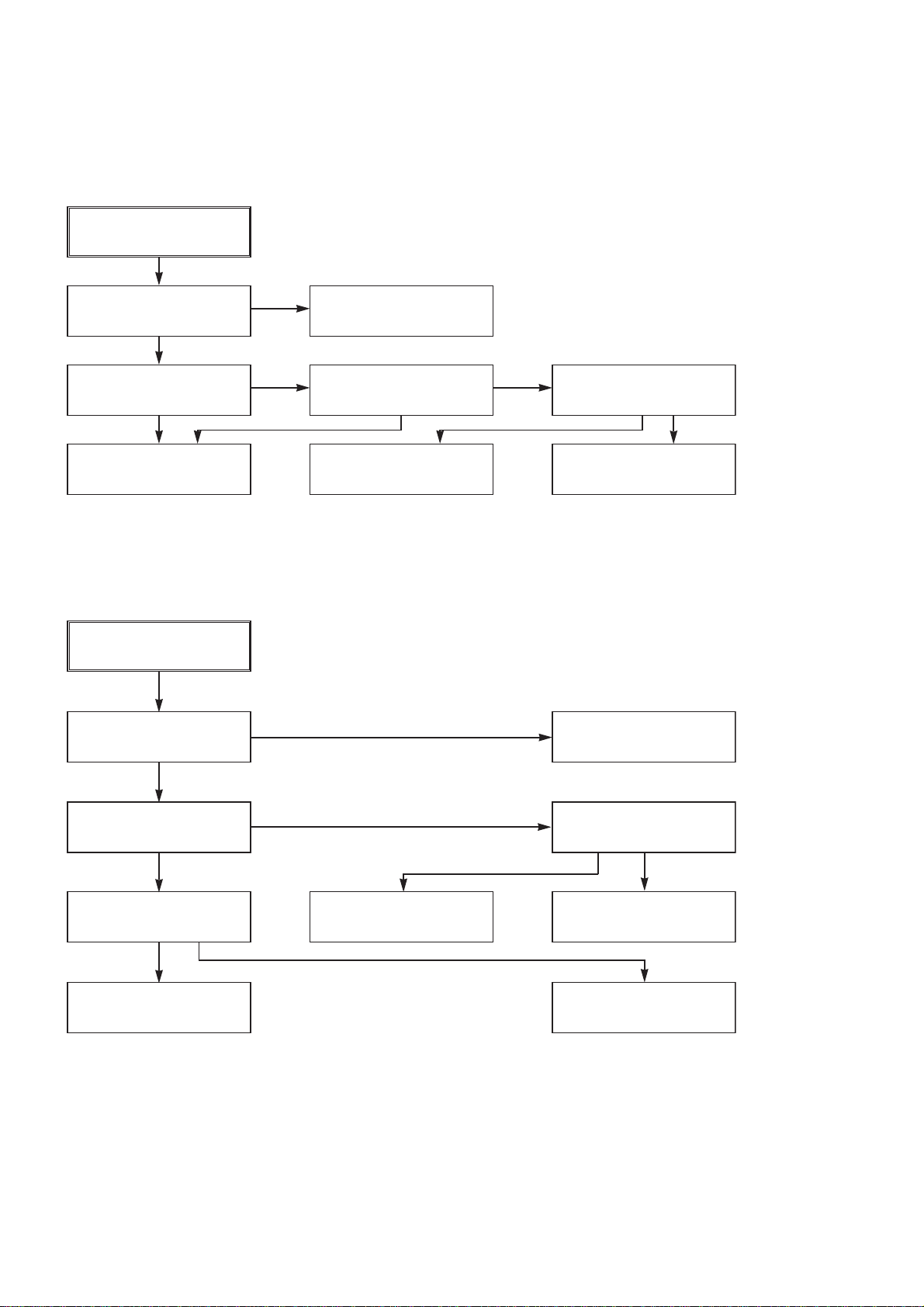
3-2. ELECTRICAL TROUBLESHOOTING GUIDE
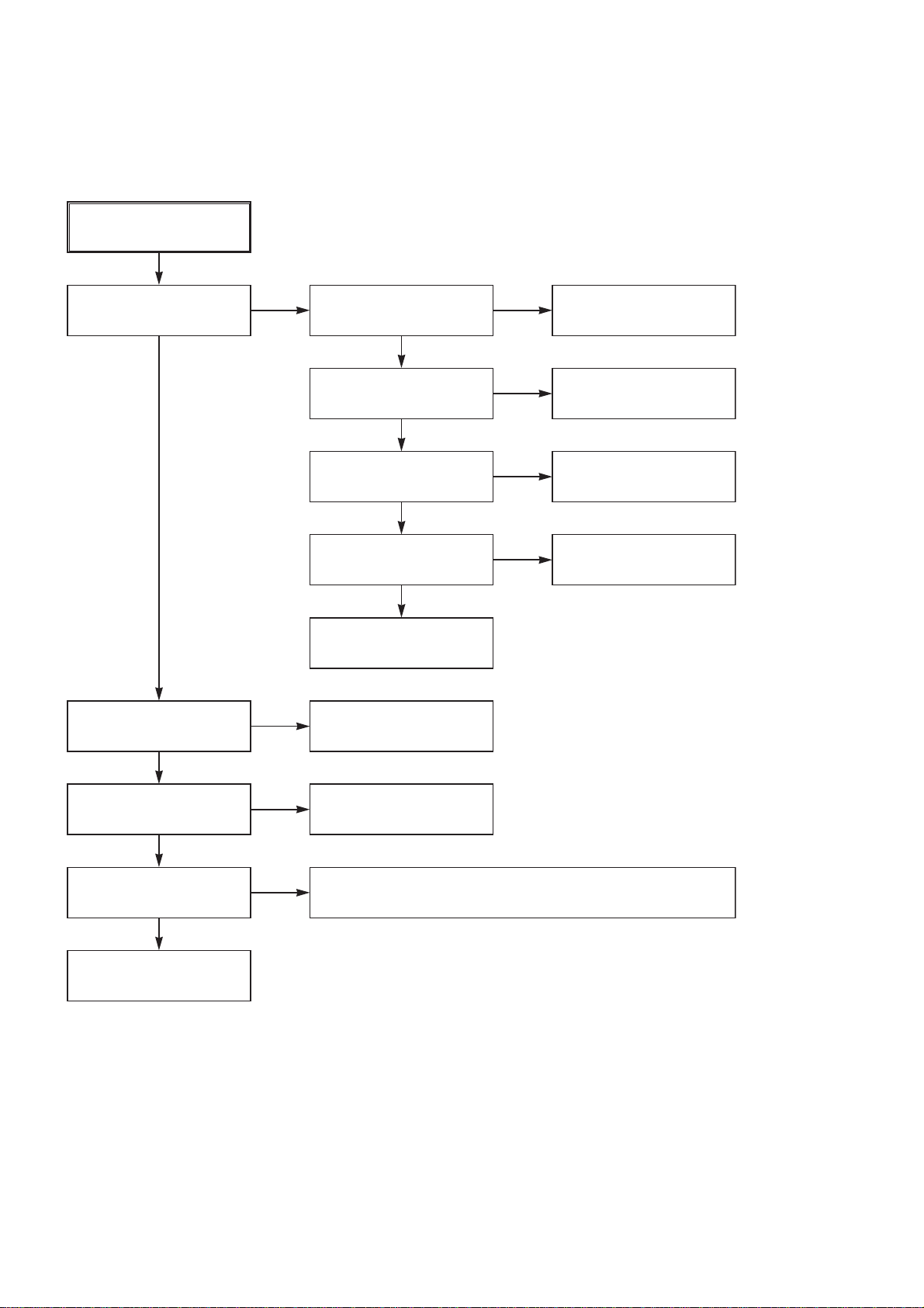
1. Power (SMPS) CIRCUIT
(1) No 5.3VA (SYS/Hi-Fi/TUNER)
NO 5.3VA.
YES
Is the F101 normal?
YES
Is the BD101
NO
NO
Replace the F101.
(Use the same Fuse)
normal?
YES
Is the R101
normal?
YES
Is Vcc(8.5~21V) sup-
NO
NO
Replace the R101.
plied to IC101 Pin7?
YES
Check or Replace
the D102.
Replace the
BD101.
Is the D102
normal?
NO
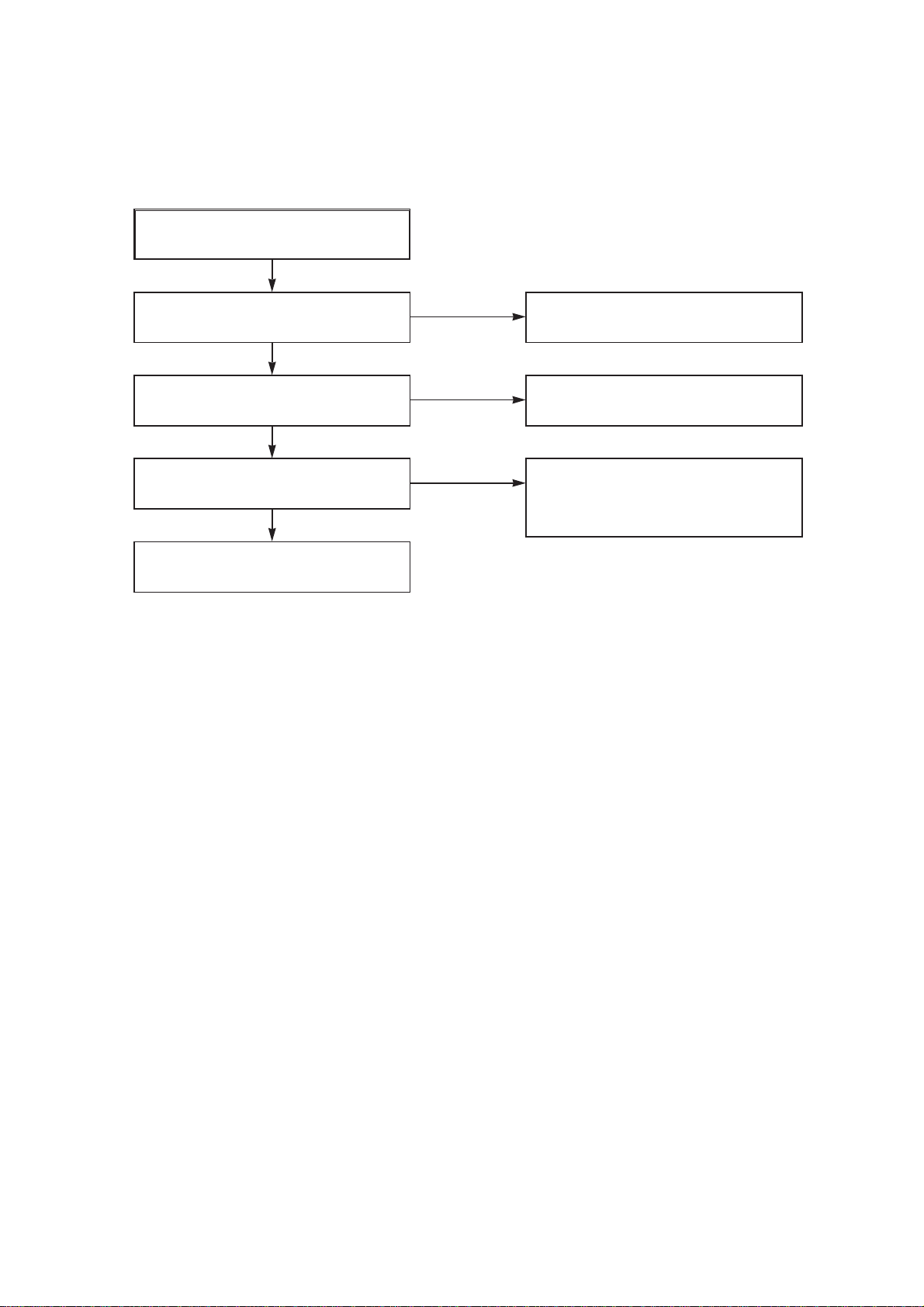
(2) No 12VA (TO CAP, DRUM MOTOR)
NO 12VA.
YES
Is the Vcc(13V) supplied
NO
to (+) terminal in D115?
YES
Is the Vcc(12V) supplied
NO
to (-) terminal in D115?
YES
Check or Replace
the D110.
Replace the D115.
Check or Replace
the Motor Vcc.
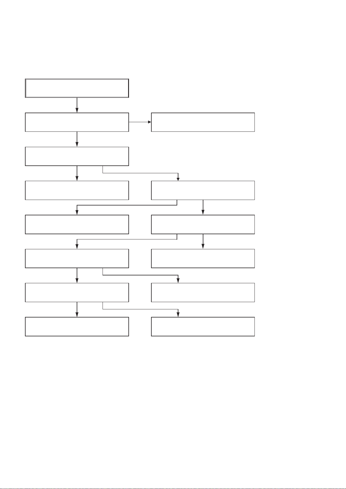
(3) No 5.0V (SYS/Hi-Fi/TUNER)
Is the D112 normal?
YES
Is there about 2.5V
at the IC103 Vref?
YES
Check the Main PCB
5.3VA/5.0V Line short?
NO
NO
Replace the D112.
Replace the IC103.
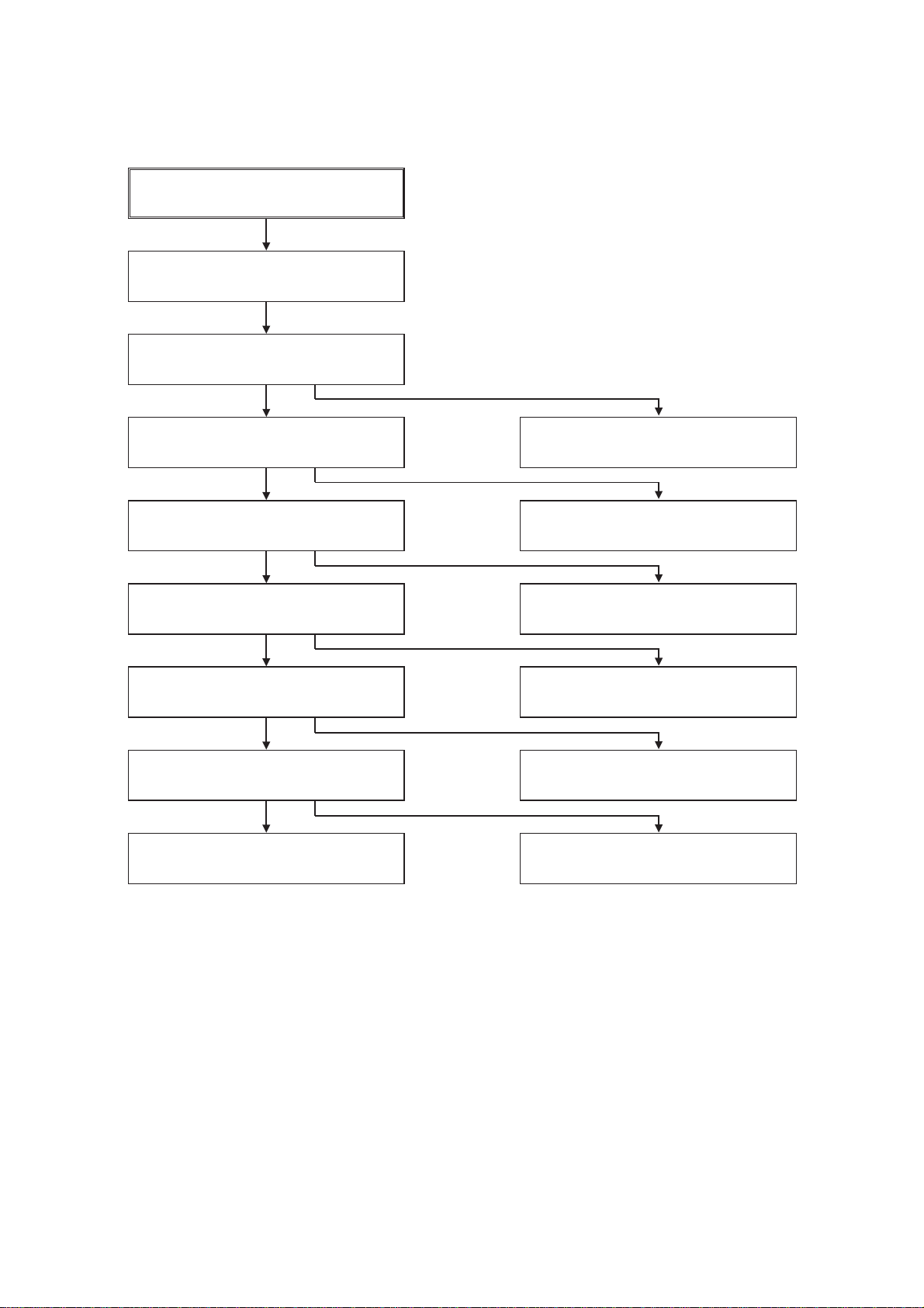
NO 5.0VA.
YES
Is 5.3VA put into
the Q160 Emitter?
YES
Is the Q162 Base
“H”?
YES
Is about 5V put into
the Q160 Base?
YES
Check or Replace
the Q162/Q160.
NO
NO
NO
5.3VA Line Check.
Check the Power
Control.
Check or Replace the
Q162, R157, R158, R159.
14

AVD-K600P
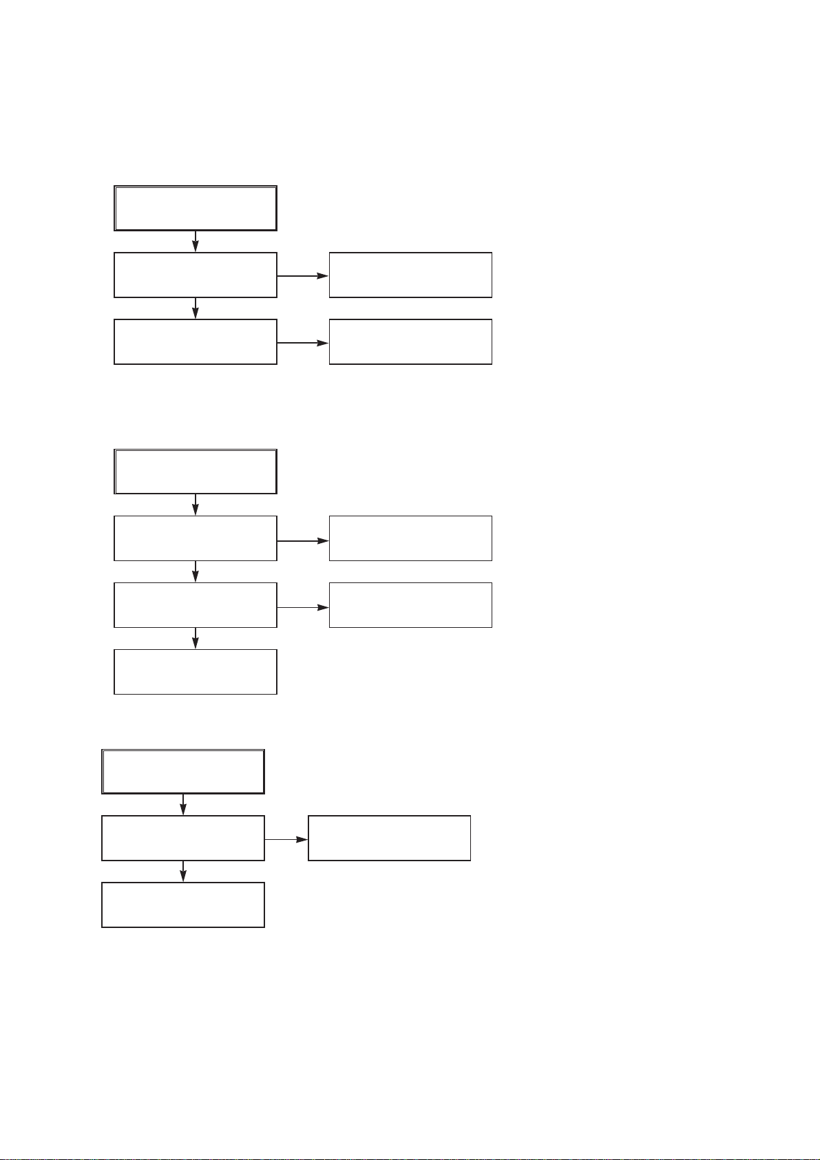
(4) No 5V (TO DVD)
NO 5V.
YES
Is 5.3VA put into
the Q160 Emitter?
YES
Is the Q162 Base
“H”?
YES
Is about 5V put into
the Q160 Base?
YES
Check or Replace
the Q162/Q160
(6) No REG 12V
NO
NO
NO
5.3VA Line Check.
Check the Power
Control.
Check or Replace the
Q162, R157, R158, R159.
(5) No 33V (TUNER)
No 33V.
YES
Is Q163 Base “H”?
YES
Check or Replace
Q161, R154, R155.
(7) No 8V(TO DVD)
NO
Check the Power
Control.
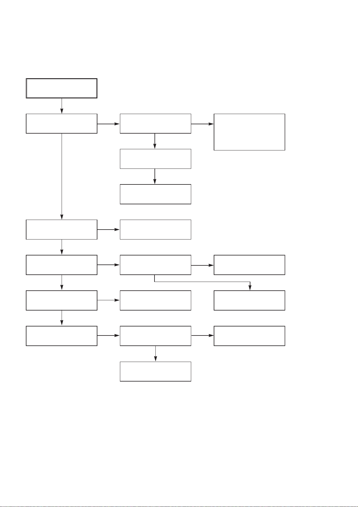
No REG 12V.
YES
Is 13V put into the
NO
Q156 Collector?
YES
Is 13V put into the
NO
R153 Base?
YES
Check or Replace the Q156,
ZD103, R153, C151.
Check or Replace
D110.
Check 33V Line.
NO 8V.
YES
Is Vcc(13V) supplied to
(+) terminal in D114?
YES
Is Vcc(12V) supplied
to IC151 Pin1?
YES
Is the Q162 Base
“H”?
YES
Check or Replace
IC151, R170, C154.
NO
NO
NO
Check or Replace
the D110.
Check or Replace
the D114.
Check the Power
Control.
15
AVD-K600P
2. SYSTEM/KEY CIRCUIT
(1) AUTO STOP
Auto Stop
YES
Does the SW30 waveform
appear at the IC501
Pin18?
YES
Do the T-UP Reel Pulses
appear at the IC501 Pin80?
YES
NO
NO NO
Check the Drum Motor
signal.
Do T/UP Reel Pulses
appear at the point
between R556 and R536?
YES YES
Does 5V appear at the
RS501?
NO
Replace the IC501.
Replace the T/UP Reel
Sensor (RS501).
(2) The unstable loading of a Cassette tape
The unstable loading of a
Cassette tape
YES
Is 12V applied to the
PMC01 Pin8?
YES
Does the “H” signal appear
at the IC501 Pin60 during
inserting the CST ?
YES
Does the “L” signal appear
at the IC501 Pin19 during
inserting the CST?
YES
NO
NO
Check the CST SW and
the peripheral circuitry.
NO
Check the Q160 Power
Circuit.
Refer to “SMPS DRUM
12 Volt Trouble Shooting”.
Is 5V applied to the
R531 ?
YES
Refer to SMPS 5.3VA
troubleshooting.
NO
Caution :
16
Check the Deck
Mechanism.
Auto stop can occur because Grease or Oil is dried up
Check the IC501
Pins22, 23, 24, 25.

3. SERVO CIRCUIT
(1) Unstable Video in PB MODE
Unstable Video in
PB Mode.
YES
Does the Noise level of the
screen change
periodically?
YES
AVD-K600P
Do the CTL pulses appear
at the IC501 Pin97?
YES
Does the CFG waveform
appear at the IC501
Pin87?
YES
On tracking do the CTL
pulses move?
YES
Does the Video Envelope
waveform appear at the
IC501 Pin9?
YES
Replace the IC501.
(2) When the Drum Motor
(2) doesn’t run.
When the Drum Motor
doesn’t run,
Does 12V appear at the
PMC01 Pin8?
NO
NO
NO
NO
Is adjusting the height of
the CTL Head accurate?
Replace the IC501.
Refer to “When the Y signal
doesn’t appear on the
screen in PB Mode”.
Refer to “(2)
No 12VA of Power section”
Do the Drum PWM Pulses
appear at the IC501
Pin76?
YES
Aren’t the foil patterns and
the Components between
IC501 Pin76 and PMC01
Pin12 short?
NO
NO
Readjust the height of the
CTL Head.
Do the DFG Pulses appear
at the PMC01 Pin11?
YES
NO
Replace the Cap M.
YES
Does 2.8V appear at the
PMC01 Pin12?
YES
Check the connector
(PMC01) and the Drum
Motor Ass’y.
NO
Do the DFG Pulses appear
at the IC501 Pin90?
YES
Do the Drum PWM Pulses
appear at the IC501
Pin76?
YES
Aren’t the connecting patterns and the Components
between IC501 Pin76 and PMC01 Pin12 short?
NO
NO
Aren’t the foil patterns and
the Components between
IC501 Pin 90 and PMC01
Pin11 short?
Replace the IC501.
17
AVD-K600P
(3) When the Capstan Motor doesn’t run,
When the Capstan Motor doesn’t run,
Does 12VAappear at the PMC01?
YES
Is “DRUM CTL” 2.8V appear at the
PMC01?
YES
Check the PMC01 and the Capstan
Motor Ass’y.
Aren’t the foil patterns and Components
between IC501 Pin77 and PMC01
Pin9 short?
Does the CFG signal come into the
IC501 Pin87?
YES
NO
NO
NO
YES
YES
Refer to “SMPS(CAPSTAN/12Volt)
Trouble Shooting”.
Does the PWM signal appear at the
IC501 Pin77?
NO
Does the CFG signal appear at the
PMC01 Pin1?
NO
Check the Capstan Motor Ass’y.
Does the Capstan PWM signal appear at
the IC501 Pin77?
YES
Aren’t the foil patterns and Components
between IC501 Pin77 and PMC01
Pin9 short?
Aren’t the foil patterns and component
between IC501 Pin87 and PMC01
Pin1 short?
NO
Replace the IC501.
18
(4) KEY doesn’t working
KEY doesn’t working.
AVD-K600P
Is 5V applied to the IC501
Pin79?
YES
Does LED or FLD change
when a function button is
pressed?
4. OSD CIRCUIT
(1) No OSD display.
No OSD or F.OSD display.
Is 5.3V applied to the
IC501 Pin53?
YES
Does oscillation occur at
the IC501 Pins44, 45?
YES
NO
NO
NO
NO
Refer to “SMPS 5.3VA
Trouble Shooting”.
Replace the defective
switches.
Refer to “SMPS 5.3VA
Trouble Shooting”.
Check or Replace the pheripheral Circurity.(L511,
R518, C596, C595)
Replace the IC501.
2
(2) I
C BUS CHECK
The I2C waves don’t
come out.
Does Power appear at the
Pull up impedence
(R569, R507)?
YES
Replace the IC501.
NO
Refer to “SMPS 5.3VA
Trouble Shooting”.
19
AVD-K600P
5. Y/C CIRCUIT
(1) No Video in EE Mode,
No Video in EE Mode
Does the Video signal
appear at the IC301
Pins28, 30, 32?
YES
Is REG 5.0V applied to the
IC301Pins23, 44, 45, 52, 68,
77?
YES
Does the Video signal
appear at the IC301 Pin26?
YES
Does the Video signal
appear at the IC501 Pin52?
NO
NO
NO
NO
Does the Video signal
appear at the IC302
Pins1, 5?
Is there 5V at the IC302
Pin6?
Replace the IC302.
Check the REG 5V Line.
(Power Circuit)
Is I2C BUS signal applied to
the IC301 Pins53, 54, 55?
Check the path of the signal between the IC301 Pin
26 and IC501 Pins50, 52.
YES
YES
YES
NO
NO
Check DVD Video Input
(IC602, Pin4), Tuner Video
Input (TU701 Pin16), Line
Video Input (JK601),
respectively.
Check the System Circuit.
(Refer to ‘SYSTEM I
CHECK Trouble Shooting’)
Replace the IC301.
2
C BUS
YES
Does the Video signal
appear at the IC602 Pin7?
NO
Is there 5V on the plus
terminal of the C614?
YES
Replace the IC602.
NO
Check the REG 5V Line.
(Power Circuit)
20

(2) When the Y(Luminance) signal doesn’t appear on the screen in PB Mode,
AVD-K600P
Is 5V applied to the IC301
Pins23, 44, 45, 52, 68, 77?
YES
Is the Y/C Bus signal
applied to the IC301
Pins53, 54, 55?
YES
Does the normal RF signal
appear at the IC301 Pin14?
YES
NO
NO
NO
Check the line of the REG
5V Line. (Power Circuit)
Refer to ‘SYSTEM Y/C
BUS CHECK Trouble
Shooting’.
Is the V.H.S/W signal
applied to the IC301 Pin57?
YES
Does the Rectangular
waveform(5V) appear at
the IC301 Pin57(V.H.S/W)
YES
Clean the Drum.
NO
NO
Check the System Circuit.
(IC501 Pin18)
Check the V.H.S/W level.
Does the Y(Luminance)
signal appear at the IC301
Pin20?
YES
Is the Y(Luminance) Video
waveform showed up at the
IC301 Pin22?
YES
Replace the IC301.
NO
NO
Check the R328, R347,
C322, C323.
Check the C324.
21

AVD-K600P
(3) When the C(Color) signal doesn’t appear on the screen in PB Mode,
Is 5V applied to the IC301
Pins23, 44, 45, 52, 68, 77?
YES
Does the fsc signal appear
at the IC301 Pins41, 50?
YES
Replace the IC301.
NO
NO
Check the line of the REG
5V Line. (Power Circuit)
Is normal the X301
(3.58MHZ) of oscillation
Frequency?
Does the Color signal
appear at the IC301 Pin48?
YES
Replace the IC301.
NO
NO
Replace the X301.
Check the C342, C341,
R333.
22

(4) When the Video signal doesn’t appear on the screen in REC Mode,
REC mode
YES
AVD-K600P
Is EE mode normal?
YES
Is brightness normal?
YES
Is the brightness signal supplied to IC301 Pins18?
YES
Check the power of Pins23,
44, 45, 52, 68, 77.
YES
Check the REG 5V power
NO
YES
YES YES
NO
Check the EE mode
Is color
Does signal appear at
IC301 Pins41, 50?
Is 5V supplied to IC301
Pins23, 44, 45, 68, 77?
Is Y/C Bus applied to
IC301 Pins53, 54, 55?
Do X301 and X-TAL
oscillate?
normal?
NO
NO
YES
YES
YES
NO
NO
NO
A
Check X301 oscillation
frequency.
Check the 5V power
Check system part
Check X301.
A
YES
Is V.H SW supplied to
IC301 Pin57?
YES
Does the FM signal appear
at IC301 Pins73(SP)/
66(EP)?
YES
Replace the IC301.
NO
NO
Check system part
(V.H/SW)
Check the drum
*OPTION
Pins72, 73, 74(SP)
Pins65, 66, 67(EP)
23
AVD-K600P
6. Tuner/IF CIRCUIT
(1) No Picture on the TV screen
No picture on the TV
screen
YES
Does the Video signal at
the TU701 Pin16.
YES
Does the video signal
appear at IC302 Pin7.
NO
NO
Is +33V applied to TU701
Pin14?
YES
Is +5V applied to TU701
Pin3?
YES
Does the Clock signal
appear at TU701 Pin9?
YES
Does the data signal
appear at TU701 Pin10?
YES
Replace Tuner.
Check the signal flow from
IC501 Pin27.(Pin27 is ‘L’
state in Tuner Mode)
NO
NO
NO
NO
Check 33V line.
Check 5V line.
Check the lIC Clock Signal
of µ-COM Pin71.
Check the lIC Data Signal
of µ-COM Pin72.
YES
Does the Video signal at
the IC501 Pin 52.
YES
Does the Video signal at
the IC602 Pin 7.
YES
Check the signal flow from IC602
Pin7 to JK601 Pin Video out.
NO
NO
Check the signal from IC301
Pin26 to IC501 Pin50.
Check the signal from IC501 Pin52 to IC602 Pin1 and IC602 Pin2.
(IC602 Pin2 is ‘L’ state in VHS mode)
24
(2) No Sound
AVD-K600P
No Sound.
YES
Check the Vcc of TU701 Pins3, 14.
YES
Check the Tuner SiF signal at IC801
Pin57.
YES
Check the Audio of IC801 Pins78, 80.
YES
Check the Signal flow from IC801 Pins78,
80 to JK601 Audio out(L), (R)
NO
NO
NO
Check 5.2V, 33V Line.
Check the Tuner SIF of TU701 Pin13.
1. Check the Vcc(5.3VA, 9V) of IC801
Pins3, 5, 36, 54.
2. Check the IIC Clock and Data at IC801
Pins37, 38.
25

AVD-K600P
7. Hi-Fi Circuit
A.
Hi-Fi Playback.
No sound
Check the Hi-Fi Selection
Switch and the Tape quality.
YES
Is the RF waveform at
IC801 Pin 23 over 3V
Vp-p?
YES
NO
Is Pin 30 of IC801 over
3.5V ?
Check IC801 Pin 37(Data),
Pin 38(Clock).
YES
NO
YES
Check the Vcc of IC801.
(Pins 3, 15, 32, 46)
YES
YES
Is the Head switching signal
IC801 Pin 39 O.K?
YES
Check the connection at
P3D01 if good then
Replace IC801.
NO
NO
Check power.
Check REC start “H” signal
of µ-COM.
NO
Check IC501 Pin 19.
(Audio Swich 30)
Is IC801 Pin 49(A.Mute)
“High”?
YES
Do Audio signals appear at
IC801 Pin 80(L-CH),
78 (R-CH)?
YES
Check the Contact point
of Audio Output.
Check Ports of µ-COM.
Check A.MUTE port of
µ-COM (Pin High of
IC501).
NO
Replace IC801.
26
B.
Hi-Fi REC.
It is impossible to record and playback
Hi-Fi Audio signal.
YES
Check Vcc of IC801. (Pins 3, 15, 32, 46)
AVD-K600P
YES
Check IC801 Pin 37(Data),Pin 38(CLOCK).
YES
Is IC501 Pin 84(A.Mute) “High”?
YES
Are Audio signals present at IC801
Pins 78, 80?
YES
Do FM Audio signals appear at IC801
Pin 26?
YES
Is IC801 Pin 17(REC “H”) “High”?
YES
NO
Check Power.
NO
Check ports of µ-COM.
NO
Check the Port of µ-COM.
NO
Check Audio Input signal Line
(9, 11, 12, 71, 73, 74), Tuner(57).
NO
Replace IC801.
NO
Check the Contact Points of Drum
Connector if good then Replace the Drum.
Check the Port of u-COM.
27
 Loading...