

Page 1
4-240-880-11(2)
Super Audio CD/
DVD RECEIVER
Operating instructions
Mode d’emploi
FR
US
FR
FR
AVD-C70ES
© 2002 Sony Corporation
Page 2
WARNING
For the customers in the
U.S.A
To prevent fire or shock
hazard, do not expose the unit
to rain or moisture.
This symbol is intended to
alert the user to the
presence of uninsulated
“dangerous voltage”
within the product’s enclosure that
may be of sufficient magnitude to
constitute a risk of electric shock to
persons.
This symbol is intended to
alert the user to the
presence of important
operating and
maintenance (servicing) instructions
in the literature accompanying the
appliance.
Owner’s Record
The model and serial numbers are
located at the rear of the unit.
Record the serial number in the
space provided below. Refer to them
whenever you call upon your Sony
dealer regarding this product.
Model No. AVD-C70ES
Serial No.______________
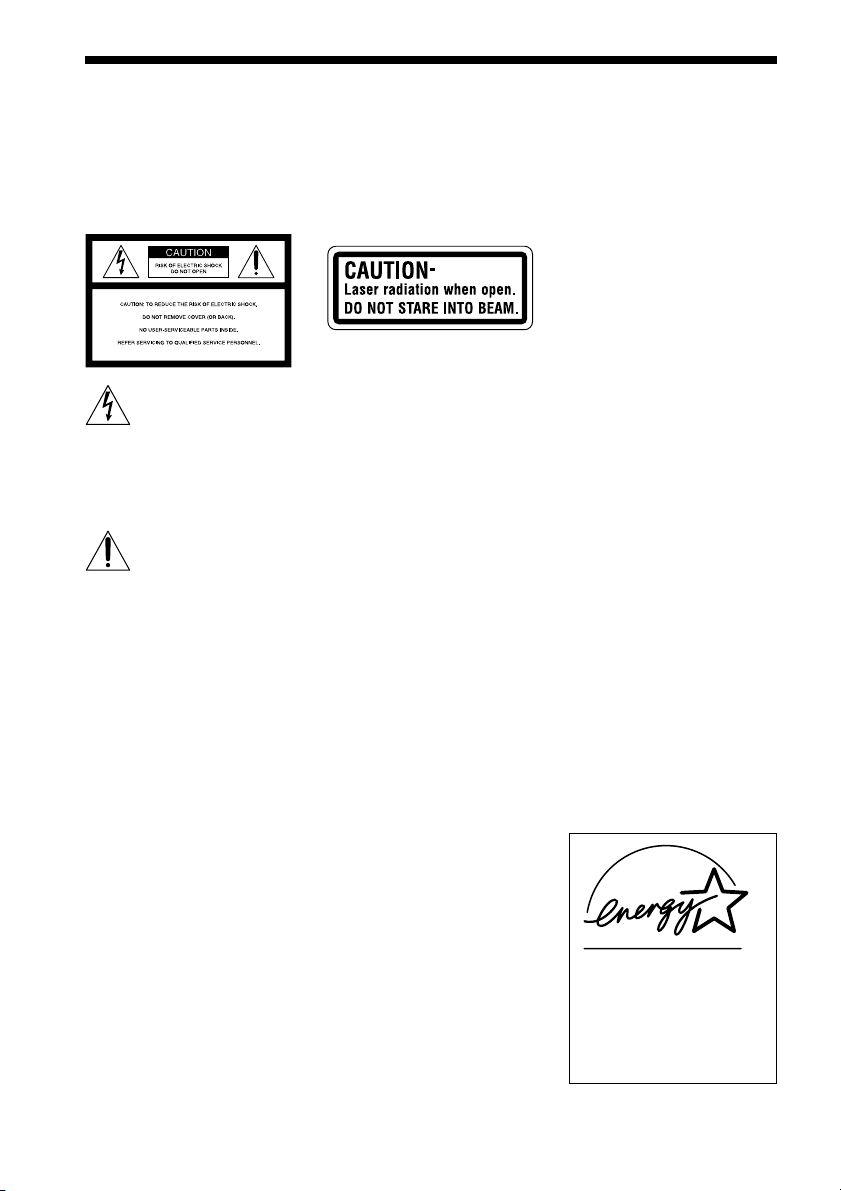
CAUTION
Use of this appliance with some
systems may present a shock or fire
hazard. Do not use with any units
which have the following marking
located near output.
“WARNING! HAZARDOUS
ENERGY!···”
CAUTION
As the laser beam used in this CD/
DVD player is harmful to eyes, do
not attempt to disassemble the
cabinet. Refer servicing to qualified
personnel only.
This label is located on the side
exterior.
WARNING
This equipment has been tested and
found to comply with the limits for a
Class B digital device, pursuant to
Part 15 of the FCC Rules. These
limits are designed to provide
reasonable protection against
harmful interference in a residential
installation. This equipment
generates, uses, and can radiate radio
frequency energy and, if not
installed and used in accordance
with the instructions, may cause
harmful interference to radio
communications. However, there is
no guarantee that interference will
not occur in a particular installation.
If this equipment does cause harmful
interference to radio or television
reception, which can be determined
by turning the equipment off and on,
the user is encouraged to try to
correct the interference by one or
more of the following measures:
- Reorient or relocate the receiving
antenna.
- Increase the separation between
the equipment and receiver.
- Connect the equipment into an
outlet on a circuit different from
that to which the receiver is
connected.
- Consult the dealer or an
experienced radio/TV technician
for help.
CAUTION
You are cautioned that any changes
or modifications not expressly
approved in this manual could void
your authority to operate this
equipment.
Note to CATV system installer:
This reminder is provided to call the
CATV system installer’s attention to
Article 820-40 of the NEC that
provides guidelines for proper
grounding and, in particular,
specifies that the cable ground shall
be connected to the grounding
system of the building, as close to
the point of cable entry as practical.
For the customers in
Canada
CAUTION
TO PREVENT ELECTRIC SHOCK,
DO NOT USE THIS POLARIZED
AC PLUG WITH AN EXTENSION
CORD, RECEPTACLE OR OTHER
OUTLET UNLESS THE BLADES
CAN BE FULLY INSERTED TO
PREVENT BLADE EXPOSURE.
ENERGY STAR
registered mark.
As an
Sony Corporation has
determined that this product
meets the
guidelines for energy efficiency.
®
is a U.S.
ENERGY STAR
ENERGY STAR
®
partner,
®
US
2
Page 3

Welcome!
Precautions
Safety
• If anything falls into the cabinet,
unplug the unit and have it
checked by qualified personnel
before operating it any further.
• The unit is not disconnected from
the mains as long as it is
connected to the mains outlet,
even if the unit itself has been
turned off.
• Unplug the unit from the wall
outlet if you do not intend to use it
for an extended period of time. To
disconnect the cord, pull it out by
the plug, never by the cord.
Installing
• Do not install the appliance in a
confined space, such as a bookcase
or built-in cabinet.
• Allow adequate air circulation to
prevent internal heat buildup.
• Do not place the unit on surfaces
(rugs, blankets, etc.) or near
materials (curtains, draperies) that
may block the ventilation slots.
• Do not install the unit near heat
sources such as radiators, or air
ducts, or in a place subject to
direct sunlight, excessive dust,
mechanical vibration, or shock.
• Do not install the unit in an
inclined position. It is designed to
be operated in a horizontal
position only.
• Keep the unit and discs away from
equipment with strong magnets,
such as microwave ovens, or large
loudspeakers.
• Do not place heavy objects on the
unit.
• If the unit is brought directly from
a cold to a warm location,
moisture may condense inside the
receiver and cause damage to the
lenses. When you first install the
unit, or when you move it from a
cold to a warm location, wait for
about 30 minutes before operating
the unit.
Thank you for purchasing this Sony
Super Audio CD/DVD RECEIVER.
Before operating this system, please
read this manual thoroughly and
retain it for future reference.
FRUS
US
3
Page 4

Precautions
On safety
• Caution – The use of optical instruments with
this product will increase eye hazard.
• Should any solid object or liquid fall into the
cabinet, unplug the receiver and have it checked
by qualified personnel before operating it any
further.
On placement
• Place the receiver in a location with adequate
ventilation to prevent heat build-up in the
receiver.
• At high volume, over long periods of time, the
cabinet becomes hot to the touch. This is not a
malfunction. However, touching the cabinet
should be avoided. Do not place the unit in a
confined space where ventilation is poor as this
may cause overheating.
• Do not block the ventilation slots by putting
anything on the receiver. The receiver is
equipped with a high power amplifier. If the
ventilation slots on the top surface are blocked,
the unit can overheat and malfunction.
• Do not place the receiver on a soft surface such
as a rug that might block the ventilation holes
on the bottom.
• Do not place the receiver in a location near heat
sources, or in a place subject to direct sunlight,
excessive dust, or mechanical shock.
On operation
• If the receiver is brought directly from a cold to
a warm location, or is placed in a very damp
room, moisture may condense on the lenses
inside the receiver. Should this occur, the
receiver may not operate properly. In this case,
remove the disc and leave the receiver turned on
for about half an hour until the moisture
evaporates.
• When you move the receiver, take out any discs.
If you don’t, the disc may be damaged.
• For power saving purposes, the receiver can be
completely turned off by the POWER button on
the main unit. Though the LED remains lit for a
while, the receiver is completely off.
On adjusting volume
Do not turn up the volume while listening to a
section with very low level inputs or no audio
signals. If you do, the speakers may be damaged
when a peak level section is played.
On cleaning
Clean the cabinet, panel, and controls with a soft
cloth slightly moistened with a mild detergent
solution. Do not use any type of abrasive pad,
scouring powder or solvent such as alcohol or
benzine.
If you have any questions or problems concerning
your receiver, please consult your nearest Sony
dealer.
On cleaning discs
Do not use a commercially available CD/DVD
cleaning disc. It may cause a malfunction.
On your TV’s color
If the speakers should cause the TV screen to have
color irregularity, turn off the TV at once then
turn it on after 15 to 30 minutes. If color
irregularity should persist, place the speakers
further away from the set.
IMPORTANT NOTICE
Caution: This receiver is capable of holding a
still video image or on-screen display image on
your television screen indefinitely. If you leave
the still video image or on-screen display image
displayed on your TV for an extended period of
time you risk permanent damage to your
television screen. Projection televisions are
especially susceptible to this.
US
4
Page 5

Table of Contents
WARNING.......................................................................................................... 2
Welcome!........................................................................................................... 3
Precautions........................................................................................................ 4
About this Manual .............................................................................................. 7
This receiver Can Play the Following Discs ....................................................... 7
Notes about the Discs........................................................................................ 9
Index to Parts and Controls ............................................................................. 10
Guide to the Control Menu Display.................................................................. 14
Getting Started ................................................................ 16
Quick Overview................................................................................................ 16
Unpacking........................................................................................................ 16
Inserting Batteries into the Remote ................................................................. 17
How to Use the Remote................................................................................... 18
Step 1: Speaker System Hookup..................................................................... 21
Step 2: Antenna Hookups ................................................................................ 23
Step 3: TV and Video Component Hookups .................................................... 25
Speaker Setup ................................................................................................. 27
Presetting Radio Stations ................................................................................ 32
Playing Discs .................................................................. 34
Playing Discs ................................................................................................... 34
Replacing Discs While Playing a Disc ............................................................. 36
Resuming Playback from the Point Where You Stopped the Disc
(Resume Play) ........................................................................................... 37
Using the DVD’s Menu ..................................................................................... 38
Playing VIDEO CDs with PBC Functions (PBC Playback) .............................. 38
Playing an MP3 Audio Track ............................................................................ 39
Selecting the Play Mode (All Discs, One Disc, or Album) ................................ 41
Creating Your Own Program (Program Play) ................................................... 42
Playing in random order (Shuffle Play) ............................................................ 44
Playing repeatedly (Repeat Play) .................................................................... 45
Searching for a Scene ....................................................... 46
Searching for a Particular Point on a Disc (Scan, Slow-motion Play) .............. 46
Searching for a Title/Chapter/Track/Index/Album ............................................. 47
continued
US
5
Page 6

Viewing Information About the Disc ....................................... 50
Viewing the Playing Time and Remaining Time on the Front Panel Display.... 50
Checking the Playing Time and Remaining Time ............................................ 51
Sound Adjustments ........................................................... 53
Changing the Sound ........................................................................................ 53
Automatically decoding the input audio signal (Auto Decoding)...................... 55
Enjoying Surround Sound................................................................................ 55
Using only the front speakers (2 Channel Stereo)........................................... 58
Adjusting the level parameters......................................................................... 58
Enjoying Movies .............................................................. 59
Changing the Angles ....................................................................................... 59
Displaying the Subtitles ................................................................................... 60
Using Various Additional Functions ....................................... 61
Locking Discs (CUSTOM PARENTAL CONTROL, PARENTAL CONTROL) ... 61
Other Operations ............................................................. 67
Controlling the other units with the Supplied Remote...................................... 67
Using the Video or other Unit........................................................................... 72
Listening to the Radio ...................................................................................... 73
Naming Preset Stations ................................................................................... 74
Settings and Adjustments ................................................... 75
Using the Setup Display .................................................................................. 75
Setting the Display or Sound Track Language (LANGUAGE SETUP)............. 76
Settings for the Display (SCREEN SETUP)..................................................... 77
Custom Settings (CUSTOM SETUP)............................................................... 79
Settings for the Speakers (SPEAKER SETUP) ............................................... 80
Additional Information ....................................................... 83
Troubleshooting ............................................................................................... 83
Self-diagnosis Function (When letters/numbers appear in the display)........... 87
Glossary .......................................................................................................... 87
Specifications................................................................................................... 90
Language Code List......................................................................................... 92
DVD Setup Menu List ...................................................................................... 93
Index ................................................................................................................ 94
US
6
Page 7
About this Manual
• The instructions in this manual describe
the controls on the remote. You can also
use the controls on the receiver if they
have the same or similar names as those on
the remote.
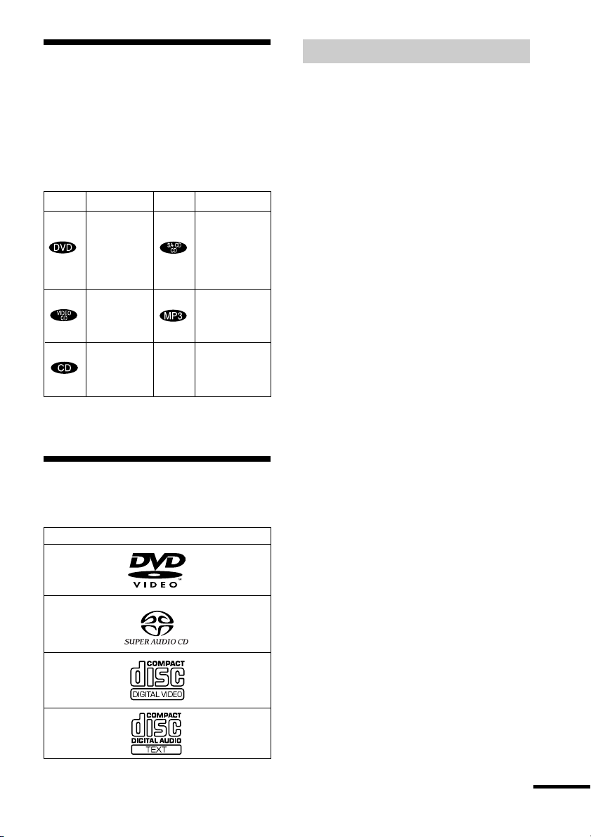
• The icons used in this manual are
explained below:
Icon Meaning Icon Meaning
z
Functions
available in
Super Audio
CD and
Audio CD
mode
Functions
available for
MP3* audio
tracks
More
convenient
features
Functions
available in
DVD video
mode
Functions
available in
VIDEO
CD mode
Functions
available in
CD mode
* MP3 (MPEG1 Audio Layer 3) is a standard format
defined by ISO/MPEG which compress audio data.
This receiver Can Play
the Following Discs
Terms for discs
• Title
The longest sections of a picture or music
feature on a DVD, movie, etc., in video
software, or the entire album in audio
software.
• Chapter
Sections of a picture or a music piece that
are smaller than titles. A title is composed
of several chapters. Depending on the disc,
no chapters may be recorded.
• Album
Section of a music piece on a data CD
containing MP3 audio tracks.
• Track
Sections of a picture or a music piece on a
VIDEO CD, Super Audio CD, CD, or
MP3.
• Index (Super Audio CD, CD) / Video
Index (VIDEO CD)
A number that divides a track into sections
to easily locate the point you want on a
VIDEO CD or Super Audio CD.
Depending on the disc, no indexes may be
recorded.
• Scene
On a VIDEO CD with PBC functions
(page 38), the menu screens, moving
pictures and still pictures are divided into
sections called “scenes.”
Format of discs
DVD VIDEO
Super Audio CD
VIDEO CD
Music CD
The “DVD VIDEO” logo is a trademark.
continued
US
7
Page 8
Disc
DVD
structure
VIDEO CD,
Super
Audio CD,
or CD
structure
MP3
structure
Title
Chapter
Track
Index
Album
Track
Disc
Disc
Note on PBC (Playback Control)
(VIDEO CDs)
This receiver conforms to Ver. 1.1 and Ver.
2.0 of VIDEO CD standards. You can enjoy
two kinds of playback depending on the disc
type.
Disc type
VIDEO CDs
without PBC
functions
(Ver. 1.1 discs)
VIDEO CDs
with PBC
functions
(Ver. 2.0 discs)
You can
Enjoy video playback
(moving pictures) as well
as music.
Play interactive software
using menu screens
displayed on the TV screen
(PBC Playback), in
addition to the video
playback functions of Ver.
1.1 discs. Moreover, you
can play high-resolution
still pictures, if they are
included on the disc.
Region code
Your receiver has a region code printed on
the back of the unit and will only play
DVDs labelled with the same region code.
DVDs labelled
ALL
will also play on this
receiver.
If you try to play any other DVD, the
message “Playback prohibited by area
limitations.” will appear on the TV screen.
Depending on the DVD, no region code
indication may be labelled even though
playing the DVD is prohibited by area
restrictions.
Examples of discs that the receiver
cannot play
The receiver cannot play the following
discs:
• CD-ROMs (PHOTO CDs included)
• CD-Rs/CD-RWs other than those recorded
in the following formats:
– music CD format
– video CD format
– MP3 format that conforms to ISO9660*
Level 1/Level 2, or its extended format,
Joliet
• Data part of CD-Extras
• DVD-ROMs
• DVD Audio discs
* A logical format of files and folders on CD-ROMs,
defined by ISO (International Standard
Organization)
Do not load the following discs:
• A DVD with a different region code (page
8, 89).
• A disc that is neither standard nor circular
(e.g., card, heart, or star shape).
• A disc with paper or stickers on it.
• A disc that has the adhesive, cellophane
tape, or a sticker still left on it.
Note
Some CD-Rs or CD-RWs cannot be played on this
receiver depending upon the recording quality or
physical condition of the disc, or the characteristics
of the recording device.
Furthermore, the disc will not play if it has not been
correctly finalized. For more information, see the
US
8
operating instructions for the recording device.
Page 9
Note on playback operations of
DVDs and VIDEO CDs
Notes about the Discs
Some playback operations of DVDs and
VIDEO CDs may be intentionally set by
software producers. Since this receiver plays
DVDs and VIDEO CDs according to the
disc contents the software producers
designed, some playback features may not
be available. Also, refer to the instructions
supplied with the DVDs or VIDEO CDs.
Copyrights
This product incorporates copyright
protection technology that is protected by
method claims of certain U.S. patents, other
intellectual property rights owned by
Macrovision Corporation, and other rights
owners. Use of this copyright protection
technology must be authorized by
Macrovision Corporation, and is intended
for home and other limited viewing uses
only unless otherwise authorized by
Macrovision Corporation. Reverse
engineering or disassembly is prohibited.
This system incorporates with Dolby*
Digital and Dolby Pro Logic (II) adaptive
matrix surround decoder and the DTS**
Digital Surround System.
* Manufactured under license from Dolby
Laboratories.
“Dolby”, “Pro Logic” and the double-D symbol
are trademarks of Dolby Laboratories.
**Manufactured under license from Digital Theater
Systems, Inc.
“DTS” and “DTS Digital Surround” are
trademarks of Digital Theater Systems, Inc.
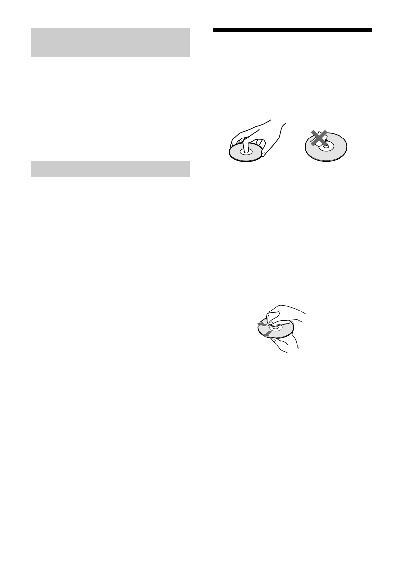
On handling discs
• To keep the disc clean, handle the disc by
its edge. Do not touch the surface.
• Do not stick paper or tape on the disc.
• Do not expose the disc to direct sunlight or
heat sources such as hot air ducts, or leave
it in a car parked in direct sunlight as the
temperature may rise considerably inside
the car.
• After playing, store the disc in its case.
On cleaning
• Before playing, clean the disc with a
cleaning cloth.
Wipe the disc from the center out.
• Do not use solvents such as benzine,
thinner, commercially available cleaners,
or anti-static spray intended for vinyl LPs.
This system can only play back a standard
circle disc. Using neither standard nor
circular discs (e.g., card, heart, or star shape)
may cause a malfunction.
Do not use a disc that has a commercially
available accessory attached, such as a label
or ring.
US
9
Page 10
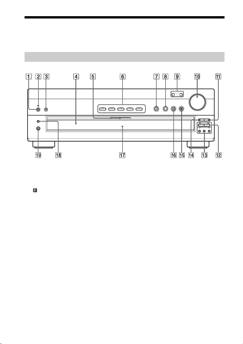
Index to Parts and Controls
For more information, refer to the pages indicated in parentheses.
Front Panel
DISPLAY
PHONES
1 POWER switch (34)
2 STANDBY indicator (34)
(remote sensor) (17)
3
4 Disc tray (34)
5 MULTI CHANNEL DECODING
indicator
6 DISC 1 – 5 (34)
7 A (open/close) (34)
8 H (play) (34)
9 FUNCTION –/+ (72)
0 VOLUME control (34, 82)
DISC 1 DISC 2 DISC 3 DISC 4 DISC 5
qa EX-CHANGE (36)
qs ./>, PRESET +/– (35)
qd SOUND FIELD AUTO DEC/2CH ST/
qf DISC SKIP (34)
qg x (stop) (35)
qh X (pause) (35)
qj Front panel display (11)
qk DISPLAY (73)
ql PHONES jack (34)
FUNCTION
–
MODE (55, 56, 58)
VOLUME
+
DISC SKIP
EX-CHANGE
–+
PRESET
SOUND FIELD
2CH STAUTO DEC MODE
10
US
Page 11
Front Panel Display
When playing back a DVD
Current play
mode Current chapter number
Playing status
Current sound
DVD
Lights up when you can
change the angle
REPEAT1
TITLE CHAPTER H M S PCM
ANGLE
Current title
number
Playing time
When playing back a Super Audio CD, CD, VIDEO CD, or MP3
Current disc
SACD
CD MP3
VIDEO CD
Lights up during
MP3 playback
Current play mode
PROGRAM
SHUFFLE
Lights up during
PBC playback
(VIDEO CD only)
REPEAT1
PBC
Playing status
Current index number
(The index indicator does not appear during
Super Audio CD or MP3 playback.)
TRACK INDEX M S PCM
Current track number
Playing time
When listening to the radio
Preset number Monaural/Stereo effect
DIGITAL
PRO
Current surround
format
DTS
LOGIC
Current sound
FM AM
Current band
TUNED MONO ST
Current station
MHz
continued
11
US
Page 12
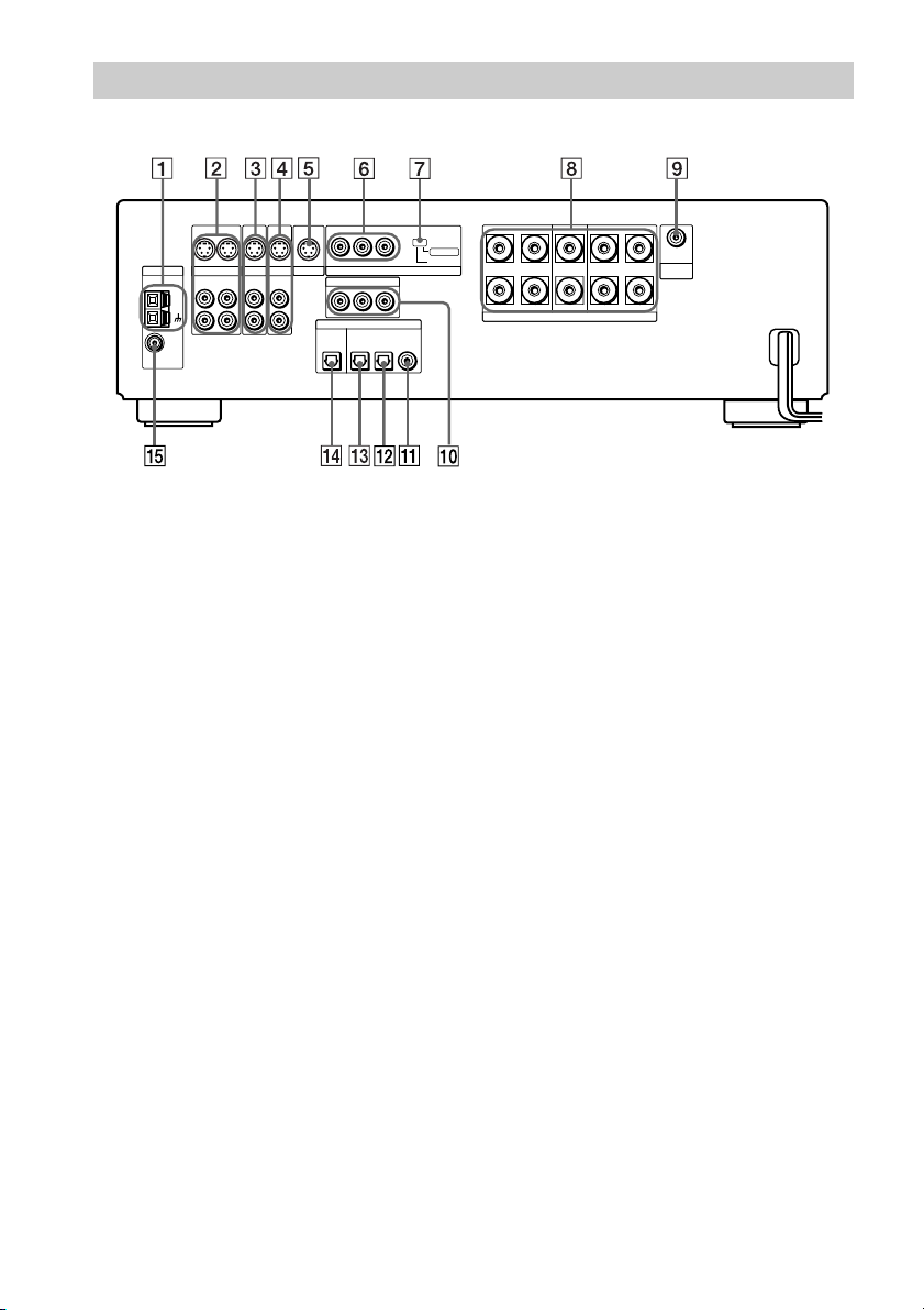
Rear Panel
ANTENNA
AM
FM
75Ω
COAXIAL
S VIDEO S VIDEO
OUT OUTIN
VIDEO
ANALOG ANALOG
OUT IN
L
R
TV/SAT
IN
IN
S VIDEO S VIDEO
IN
MONITOR
AUX
ANALOG
IN
L
R
YPB/CBPR/C
COMPONENT VIDEO IN
YPB/CBPR/C
OPTICAL
MD/DAT
OUT
R
SCAN SELECT
COMPONENT VIDEO OUT
R
DIGITAL
OPTICAL IN
COAXIAL IN
TV/SAT AUX
SELECTABLE
INTERLACE
SURROUND
SPEAKERS
ANALOG
OUT
SUB
IMPEDANCE USE 6–16Ω
LR
WOOFER
FRONTCENTER
LR
1 AM antenna (23)
2 VIDEO (S VIDEO/ANALOG L/R IN/
OUT) jacks (25)
3 TV/SAT (S VIDEO/ANALOG L/R IN)
jacks (25)
4 AUX (S VIDEO/ANALOG L/R IN)
jacks
5 MONITOR (S VIDEO OUT) jack (25)
6 COMPONENT VIDEO OUT jacks (25)
7 COMPONENT VIDEO OUT switch
(78, 83)
8 SPEAKERS jacks (21)
9 SUB WOOFER (ANALOG OUT) jack
(21)
0 COMPONENT VIDEO IN jacks (26)
qa AUX (COAXIAL IN) jack
qs TV/SAT (OPTICAL IN) jack (26)
qd MD/DAT (OPTICAL IN) jack
qf OPTICAL OUT jack
qg FM 75Ω COAXIAL antenna jack (23)
12
US
Page 13
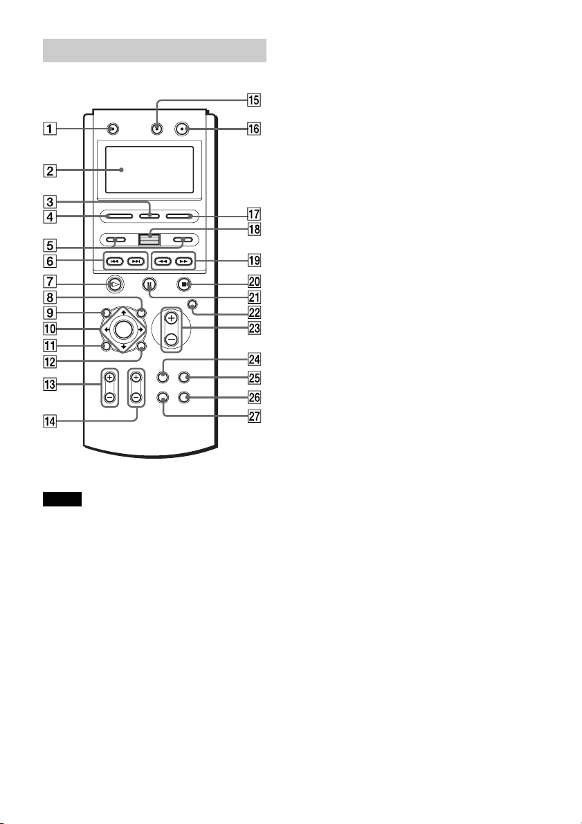
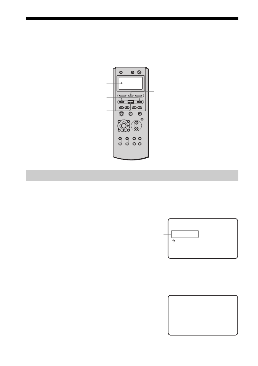
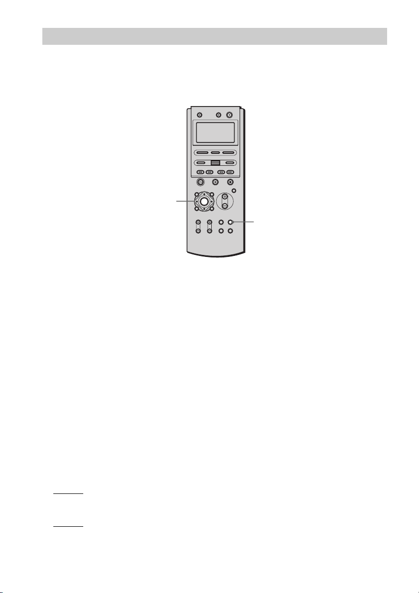
Remote
1 TV [/1 (on/standby) (68)
2 Display (18)
3 RM SETUP (18, 67)
4 SOUND FIELD (55)
5 </> (18)
6 ./>, CH +/– (35)
7 H (play) (34)
8 AV MENU (38)
9 TOP MENU/GUIDE (38)
0 C/X/x/c/ENTER (38)
qa DVD DISPLAY (14, 39)
qs O RETURN/EXIT (39)
qd TV VOL +/– (68)
qf TV CH +/– (68)
qg AV [/1 (on/standby) (69)
qh [/1 (on/standby) (34)
qj FUNCTION (72)
qk Scroll key (32)
ql m/M (32, 46)
w; x (stop) (34)
wa X (pause) (35)
ws MUTING (35)
wd VOLUME +/– (73, 82)
wf TV/VIDEO (68)
wg AMP MENU (28)
wh DVD SETUP (75)
wj WIDE (68)
Notes
• The remote’s display disappears automatically if
you don’t press any button for more than 10
seconds.
•This remote control glows in the dark. However,
before glowing, the remote must be exposed to
light for awhile.
13
US
Page 14
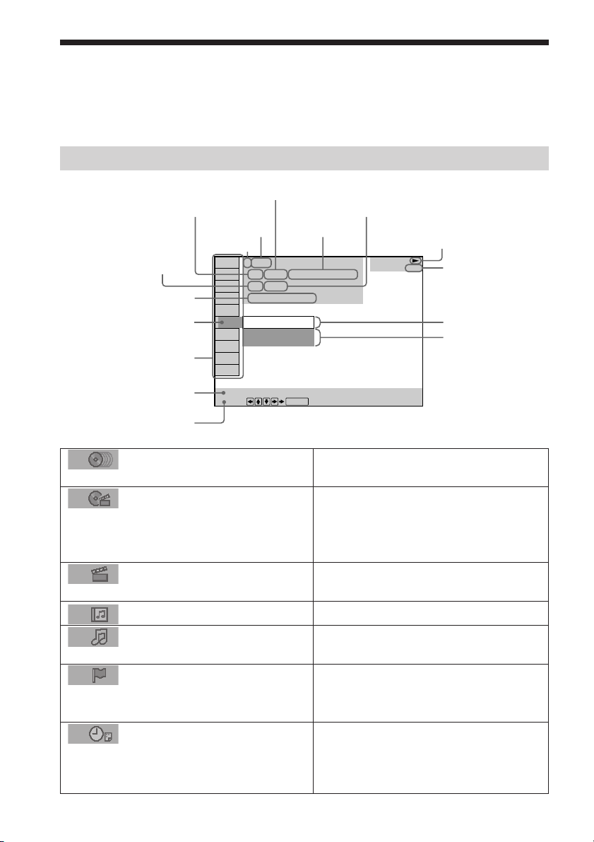
Guide to the Control Menu Display
Use the Control Menu to select a function that you’d like to use. The Control Menu display
appears when the DVD DISPLAY button is pressed. For details, refer to the page in
parentheses.
Control Menu
Total number of titles
Current playing title number (Video CD/
Super Audio CD/CD: track number)
Current playing chapter
number (Video CD/Super
Audio CD/CD: index number)
Playing time
Icon of selected
Control Menu item
Control Menu items
Disc number
or tracks recorded
Disc name
or disc type
1:DVD
1 2 ( 2 7 ) MAKING SCENE
1 8 ( 3 4
T
1 : 3 2 : 5 5
1: ENGLISH
2: FRENCH
3: SPANISH
Current playing
title name
)
Total number of chapters or indexes recorded
Playback status
(NPlayback, XPause, xStop, etc.)
DVD
Type of disc being
played back
Current setting
Options
Function name of selected
Control Menu item
Operation message
List of Control Menu Items
DISC
TITLE (DVD only) (page 47)/
SCENE (only VIDEO CD in PBC
playback)/TRACK (VIDEO CD only)
(page 47)
CHAPTER (DVD only) (page
48)/INDEX (VIDEO CD only) (page 48)
ALBUM (MP3 only) (page 47)
TRACK (Super Audio CD/
CD/MP3 only) (page 47)
INDEX (Super Audio CD/CD only)
(page 48)
TIME (page 49)
US
14
SUBTITLE
Select:
ENTER
Displays the disc name or the disc type
inserted into the receiver.
Selects the title (DVD), the scene (VIDEO
CD in PBC playback), or the track
(VIDEO CD) to be played.
Selects the chapter (DVD) or the index
(VIDEO CD) to be played.
Selects the album (MP3) to be played.
Selects the track (Super Audio CD/CD/
MP3) to be played.
Displays the index (Super Audio CD/CD).
Selects the index (Super Audio CD only) to
be played.
Checks the elapsed time and the remaining
playback time.
Inputs the time code for picture and music
searching.
Page 15
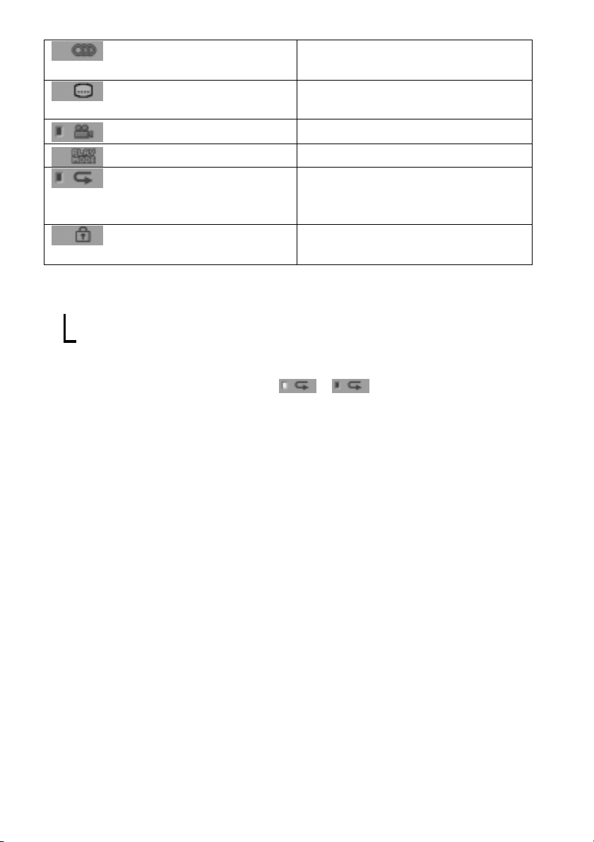
AUDIO (DVD/VIDEO CD/
Changes the audio setting.
Super Audio CD/CD only) (page 53)
SUBTITLE (DVD only) (page
60)
ANGLE (DVD only) (page 59)
PLAYMODE (page 41)
REPEAT (page 45)
Displays the subtitles.
Changes the subtitle language.
Changes the angle.
Selects the play mode.
Plays the entire disc (all titles/all tracks),
one title/chapter/track/album, or contents
of program repeatedly.
CUSTOM PARENTAL
Sets the disc to prohibit playing.
CONTROL(page 61)
z Each time you press DVD DISPLAY, the Control Menu display changes as follows:
Control Menu display
,
m
Control Menu display off
The Control Menu items are different depending on the disc.
z The Control Menu icon indicator lights up in green t unless you set the REPEAT setting to
“OFF.”
The “ANGLE” indicator lights up in green only when the angles can be changed.
15
US
Page 16

Getting Started
Quick Overview
This chapter presents a quick overview so you can begin enjoying your new receiver right away.
For selecting a language used in the on-screen display, refer to the page 76.
For selecting the aspect ratio of the TV to be connected, refer to the page 77.
Unpacking
Check that you have the following items:
• AM loop antenna (1)
• FM wire antenna (1)
• S Video cord (1)
• Remote Commander (remote) RM-CL70 (1)
• R6 (size AA) batteries (3)
16
US
Page 17
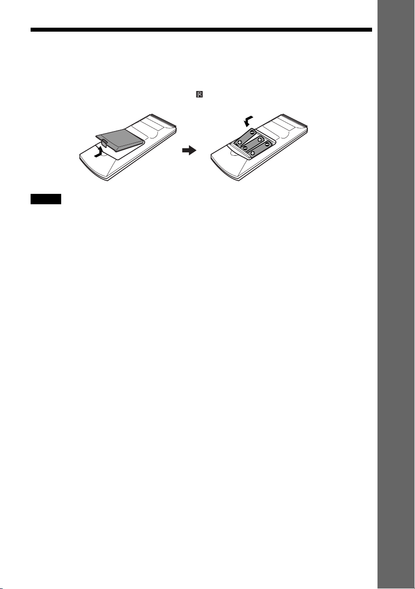
Inserting Batteries into the Remote
You can control the receiver using the supplied remote. Insert three R6 (size AA) batteries by
matching the 3 and # ends on the batteries to the markings inside the compartment. When
using the remote, point it at the remote sensor on the receiver.
Notes
• Do not leave the remote in an extremely hot or humid place.
• Do not use a new battery with an old one.
• Do not drop any foreign object into the remote casing, particularly when replacing the batteries.
• Do not expose the remote sensor to direct light from the sun or lighting apparatus. Doing so may cause a
malfunction.
• If you do not use the remote for an extended period of time, remove the batteries to avoid possible damage from
battery leakage and corrosion.
Getting Started
17
US
Page 18
How to Use the Remote
VIDEO>
* 2
* 3
<
* 1
You can operate the receiver and other units with the remote. This remote has a display that
shows the current unit being operated, or the current status during setup. With the Scroll key,
you can easily select a function, or confirm a setting for various setup procedures.
Display
</>
Scroll key
About the remote’s display
The remote’s display displays the unit being operated, or the current status of the remote as
shown below. It also has a backlight that lights up when you press the Scroll key or buttons
during unit operations.
RM SETUP
To select the operatable unit
Press </> until the desired source appears in the
remote’s display.
Each time you press >, the source changes as
follows.
<PLAYER> t <NUM> t <DISC> t
<TUNER> t <VIDEO> t <SAT> t
<CABLE> t <PLAYER>...
You can operate the TV with the remote in any selection. For details of TV operation, see “Controlling TVs
z
with the remote” on page 68.
When you operate the receiver
Select “<PLAYER>,” “<NUM>,” “<DISC>,” or “<TUNER>.”
If you don’t press any button for more than 10
seconds, the remote display changes as shown in
the illustration on the right.
US
18
Source
>EIDVD REC ERV<
ySon
<>TV
ySon
Page 19
When you operate the VCR
Select “<VIDEO>.”
When you don’t press any button for more than
10 seconds, the remote display changes as the
illustration on the right. For details of the VCR
operation, see “Controlling VCRs with the
remote” on page 69.
When you operate the satellite receiver
Select “<SAT>.”
When you don’t press any button for more than
10 seconds, the remote display changes as the
illustration on the right. For details of the
satellite receiver operation, see “Controlling
satellite receivers with the remote” on page 68.
When you operate the cable tuner
Select “<CABLE>.”
When you don’t press any button for more than
10 seconds, the remote display changes as the
illustration on the right. For details of the
satellite receiver operation, see “Controlling
cable tuners with the remote” on page 70.
Notes
• When you operate the receiver (AVD-C70ES), press </> repeatedly until “<PLAYER>,” “<NUM>,” “<DISC>,”
or “<TUNER>” appears in the remote’s display.
• When you operate the TV, VCR, satellite receiver, or cable tuner with the remote, you need to set the
manufacturer codes for each unit. To set the manufacturer codes, see “Setting the remote for controlling the other
units” on page 67.
O>V<IDE
ySon
<>TV
ySon
><SAT
ySon
<>TV
ySon
><ACBLE
/lReinHam
<>TV
ySon
Getting Started
continued
19
US
Page 20
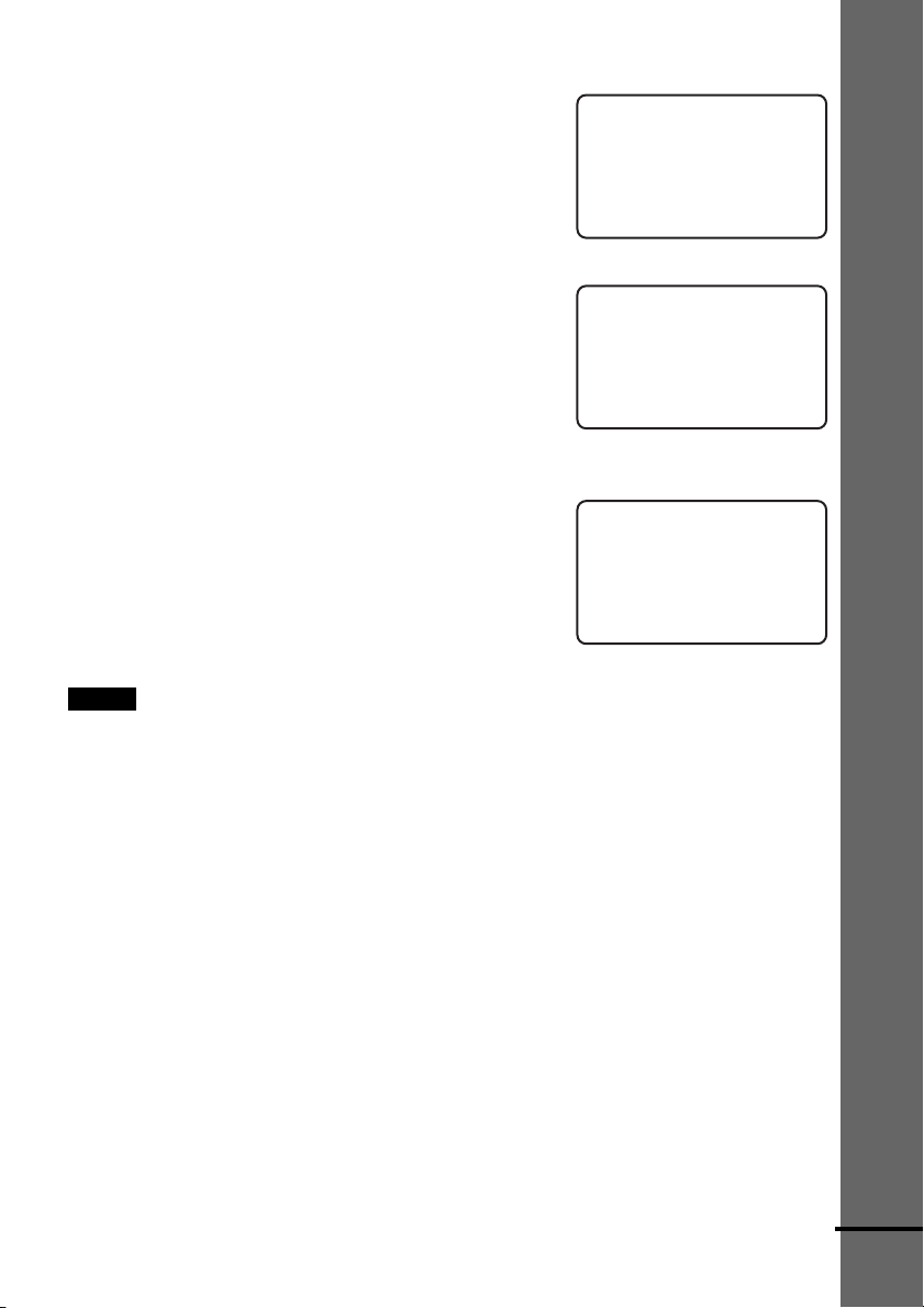
To turn the backlight of the display on and off
1 Press RM SETUP.
RM S ET
BACK L I GHT
TCON
TRRAS
ALL
CLEA
2 Move the cursor (c) to “<BACK LIGHT>”
by using the Scroll key, then press the Scroll
key.
BACK GHLI T
><
ON
OFF
3 Move the cursor (c) to “ON” or “OFF” by using the Scroll key, then press the Scroll key.
To adjust the contrast of the display
1 Press RM SETUP.
RM S ET
BACK L I GHT
TCON
TRRAS
ALL
CLEA
2 Move the cursor (c) to “<CONTRAST>” by
using the Scroll key, then press the Scroll
key.
CONT S TRA–><
+
3 Move the cursor (c) to “+” or “–” by using the Scroll key, then press the Scroll key
repeatedly until the desired setting required.
To return to the previous display, select
“EXIT” then press the Scroll key.
CONT
+
Ex i t
Note
The remote’s display disappears automatically if you don’t press any button for more than 10 seconds.
US
20
STRA–><
Page 21
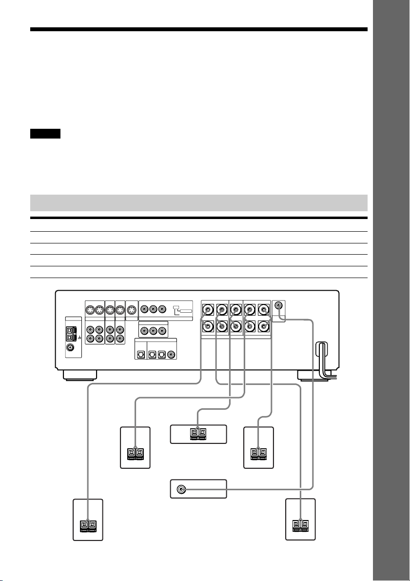
Step 1: Speaker System Hookup
You can enjoy surround sound by connecting 5 speakers (front L/R speakers, center speaker,
rear L/R speakers) and active subwoofer to the receiver. If you do not connect 5 speakers and
active subwoofer to the receiver, the receiver offers the means to optimize signal depending on
the number of connected speakers. When you connect 2 speakers to the receiver, connect the
speakers to the SPEAKERS FRONT L/R jacks.
Notes
• Be sure to match the speaker cord to the appropriate terminal: 3 to 3, # to #, L to L, and R to R jack.
• Use the high performance speakers.
• Use the same size and performance speakers for the front, center, and rear speakers.
• To obtain the best possible surround sound, specify the speaker parameters (number, distance, level, etc.) on page
28.
Terminals for connecting the speakers
Connect the To the
Front speakers SPEAKERS FRONT L and R terminals
Rear speakers SPEAKERS SURROUND L and R terminals
Center speaker SPEAKERS CENTER terminal
Subwoofer SUBWOOFER ANALOG OUT terminal
S VIDEO S VIDEO
S VIDEO S VIDEO
YPB/CBPR/C
ANTENNA
FM
75Ω
COAXIAL
AM
OUT OUTIN
VIDEO
OUT IN
L
R
TV/SAT
ANALOG ANALOG
IN
IN
MONITOR
AUX
ANALOG
IN
IN
L
R
COMPONENT VIDEO IN
YPB/CBPR/C
OPTICAL
OUT
MD/DAT
R
SCAN SELECT
COMPONENT VIDEO OUT
R
DIGITAL
OPTICAL IN
COAXIAL IN
TV/SAT AUX
SELECTABLE
INTERLACE
SURROUND
SPEAKERS
ANALOG
OUT
SUB
IMPEDANCE USE 6–16Ω
LR
WOOFER
FRONTCENTER
LR
Getting Started
+–
Rear speaker (R)
+–
Front speaker (R)
+–
Center speaker
Subwoofer
(active type)
+–
Front speaker (L)
Rear speaker (L)
+–
21
US
Page 22
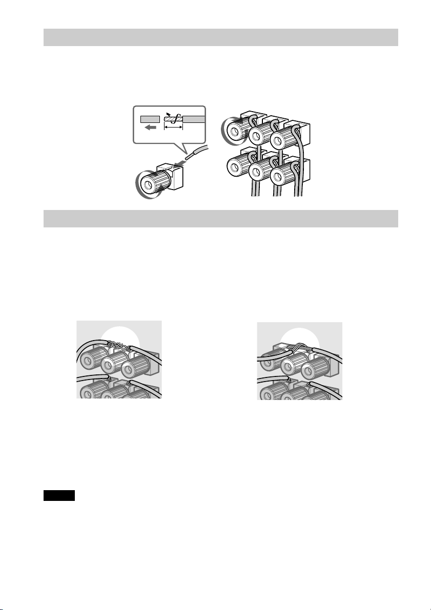
Note for connecting the speaker cords to the receiver
Remove about 10 mm of insulation at the end of the cord, then twist the exposed wires.
Connect the stripped ends of the cords to the terminals, taking care to avoid mutual contact
between the cords.
Make sure the cords are firmly connected to the speaker and receiver terminals.
10mm
To avoid short-circuiting the speakers
Short-circuiting of the speakers may damage the receiver. To prevent this, be sure to follow
these precautions when connecting the speakers. Make sure the bare wire of each speaker cord
does not touch another speaker terminal or the bare wire of another speaker cord.
Examples of poor conditions of the speaker cord
Stripped speaker cord is touching
another speaker terminal.
Stripped cords are touching each other due to
excessive removal of insulation.
After connecting all the components, speakers, and AC power cord (mains lead), output a test
tone to check that all the speakers are connected correctly. For details on outputting a test tone,
see page 30.
If no sound is heard from a speaker while outputting a test tone, or a test tone is output from a
speaker other than the one currently displayed on the front panel display, the speaker may be
short-circuited. If this happens, check the speaker connection again.
Notes
• Be sure to match the speaker cord to the appropriate terminal on the components: 3 to 3, and # to #. If the
cords are reversed, the sound will be distorted and will lack bass.
• If you use front speakers with low maximum input rating, adjust the volume carefully to avoid excessive output
on the speakers.
• When connecting the stripped ends of the speaker cords, make sure the ends do not touch each other or
neighboring terminals.
US
22
Page 23
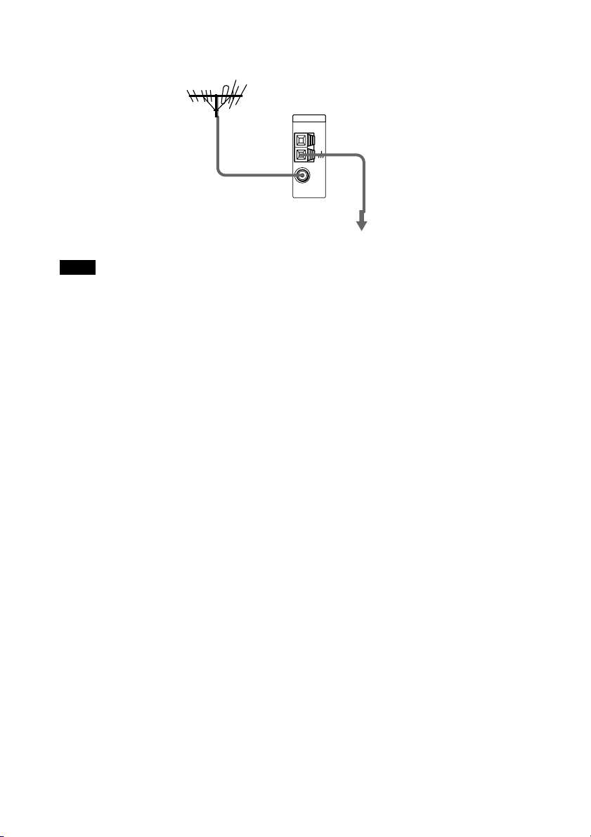
Step 2: Antenna Hookups
Connect the supplied AM/FM antennas for listening to the radio.
Terminals for connecting the antennas
Connect the To the
AM loop antenna AM terminals
FM wire antenna FM 75Ω COAXIAL terminal
AM loop antenna
S VIDEO S VIDEO
S VIDEO S VIDEO
YPB/CBPR/C
ANTENNA
COAXIAL
OUT OUTIN
OUT IN
L
AM
R
FM
75Ω
VIDEO
ANALOG ANALOG
TV/SAT
IN
IN
MONITOR
AUX
ANALOG
IN
IN
L
R
Notes
• To prevent noise pickup, keep the AM loop antenna away from the receiver and other components.
• Be sure to fully extend the FM wire antenna.
• After connecting the FM wire antenna, keep it as horizontal as possible.
• When you connect the supplied AM loop antenna, connect the black cord (B) to the U terminal, and the white
cord (A) to the other terminal.
COMPONENT VIDEO OUT
COMPONENT VIDEO IN
YPB/CBPR/C
DIGITAL
OPTICAL IN
OPTICAL
OUT
MD/DAT
TV/SAT AUX
FM wire antenna
R
R
COAXIAL IN
SCAN SELECT
SELECTABLE
INTERLACE
SURROUND
SPEAKERS
ANALOG
OUT
SUB
IMPEDANCE USE 6–16Ω
LR
WOOFER
FRONTCENTER
LR
Getting Started
A
B
AM
continued
23
US
Page 24
z If you have poor FM reception
Use a 75-ohms coaxial cable (not supplied) to connect the receiver to an outdoor FM antenna as shown below.
Outdoor FM antenna
Receiver
ANTENNA
FM
75Ω
COAXIAL
Earth wire
AM
(not supplied)
To earth
Note
If you connect the receiver to an outdoor antenna, ground it to protect against lightning. To prevent a gas explosion,
do not connect the earth wire to a gas pipe.
24
US
Page 25
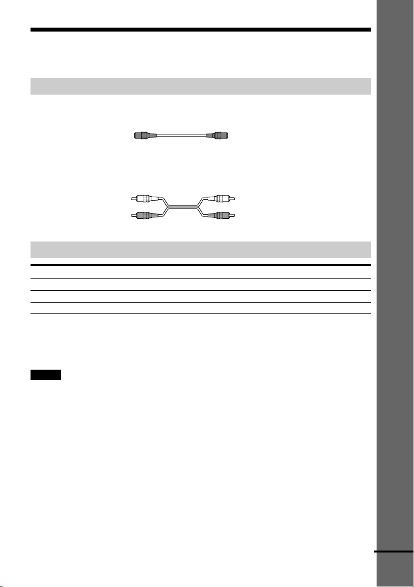
Step 3: TV and Video Component Hookups
Required cords
S Video cord for connecting a TV monitor
Audio cords (not supplied)
When connecting a cord, be sure to match the color-coded pins to the appropriate jacks on the
components.
Getting Started
White (L/audio)
Red (R/audio)
White (L/audio)
Red (R/audio)
Jacks for connecting video components
Connect a To the
TV monitor MONITOR (S VIDEO OUT) jack
VCR VIDEO (S VIDEO/ANALOG L/R IN/OUT) jacks
Digital satellite receiver TV/SAT (S VIDEO/ANALOG L/R IN) jacks
z When using the COMPONENT VIDEO OUT jacks (Y, PB/CB, PR/CR) instead of the S Video jacks
Your TV monitor must also be connected via COMPONENT VIDEO OUT jacks (Y, PB/CB, PR/CR). If your TV
accept progressive format signals, you must use this connection and set “COMPONENT OUT” to
“PROGRESSIVE” in “SCREEN SETUP” (page 78).
Notes
• When you select VIDEO using the FUNCTION button, the signal is output from the front L/R speakers, but not
from the VIDEO (S VIDEO/ANALOG L/R OUT) jacks.
• When you use the Video line outputs, please set the unit to 2CH STEREO mode. If the unit is not in 2CH
STEREO mode, the line outputs may not function properly.
• When the mode of the receiver is not set to “DVD,” the signal from the COMPONENT VIDEO IN jack is output
from the COMPONENT VIDEO OUT jacks.
• When the mode of the receiver is set to “DVD” and “INTERLACE” is selected in “SCREEN SETUP,” the signal
is output from the MONITOR or COMPONENT VIDEO OUT jacks.
• When the mode of the receiver is set to “DVD” and “PROGRESSIVE” is selected in “SCREEN SETUP,” the
signal is output only from the COMPONENT VIDEO OUT jacks.
continued
25
US
Page 26
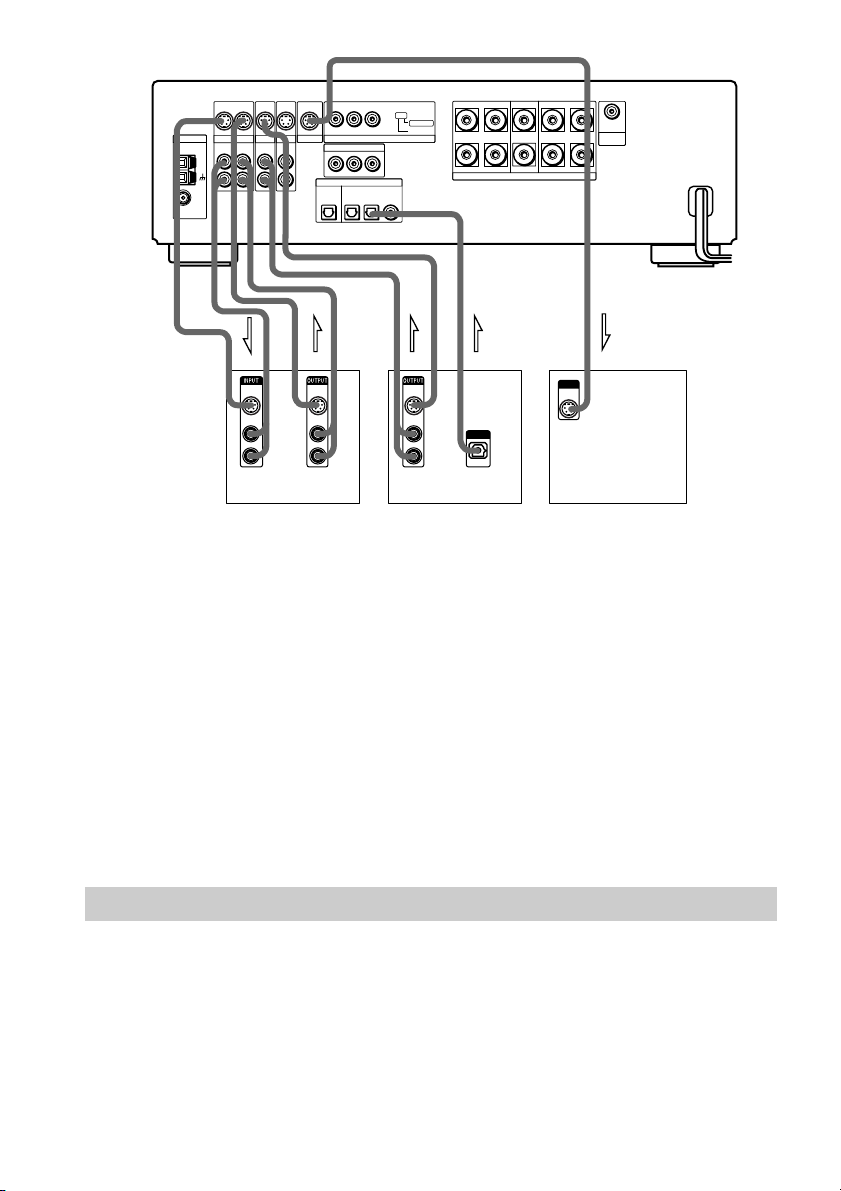
ANTENNA
FM
75Ω
COAXIAL
AM
S VIDEO S VIDEO
OUT OUTIN
VIDEO
ANALOG ANALOG
OUT IN
L
R
TV/SAT
IN
IN
S VIDEO S VIDEO
IN
MONITOR
AUX
ANALOG
IN
L
R
YPB/CBPR/C
COMPONENT VIDEO IN
YPB/CBPR/C
OPTICAL
MD/DAT
OUT
R
SCAN SELECT
COMPONENT VIDEO OUT
R
DIGITAL
OPTICAL IN
COAXIAL IN
TV/SAT AUX
SELECTABLE
INTERLACE
SURROUND
SPEAKERS
ANALOG
OUT
SUB
IMPEDANCE USE 6–16Ω
LR
WOOFER
FRONTCENTER
LR
IN INOUT OUT OUT
S VIDEO
IN
AUDIO
IN
L
R
S VIDEO
IN
AUDIO
IN
L
R
S VIDEO
IN
AUDIO
IN
L
R
OUTPUT
OPTICAL
INPUT
S VIDEO
IN
VCR Digital satellite receiver TV monitor
If you connect a digital satellite receiver with the OPTICAL OUT jack
The digital satellite receiver can be connected to the TV/SAT (OPTICAL IN) jack instead of the
ANALOG IN L/R jacks of the receiver.
The receiver can accept both the digital and analog signals. Digital signals have priority over
analog signals. If the digital signal ceases, the analog signal will be processed after 2 seconds.
If you connect a digital satellite receiver without the OPTICAL OUT jack
Connect the digital satellite receiver to the S VIDEO IN and ANALOG IN L/R jacks only of the
receiver.
If you connect a component with the COMPONENT VIDEO OUT jacks (Y, P
P
R/CR)
Connect the component to the COMPONENT VIDEO IN jacks (Y, P
B/CB, PR/CR) of the
B/CB,
receiver.
Connecting the AC Power Cord (mains lead)
Before connecting the AC power cord (mains lead) of this receiver to a wall outlet (mains),
connect the speakers to the receiver (see page 21).
Connect the AC power cord (mains lead) of your TV/video components to a wall outlet (mains).
US
26
Page 27
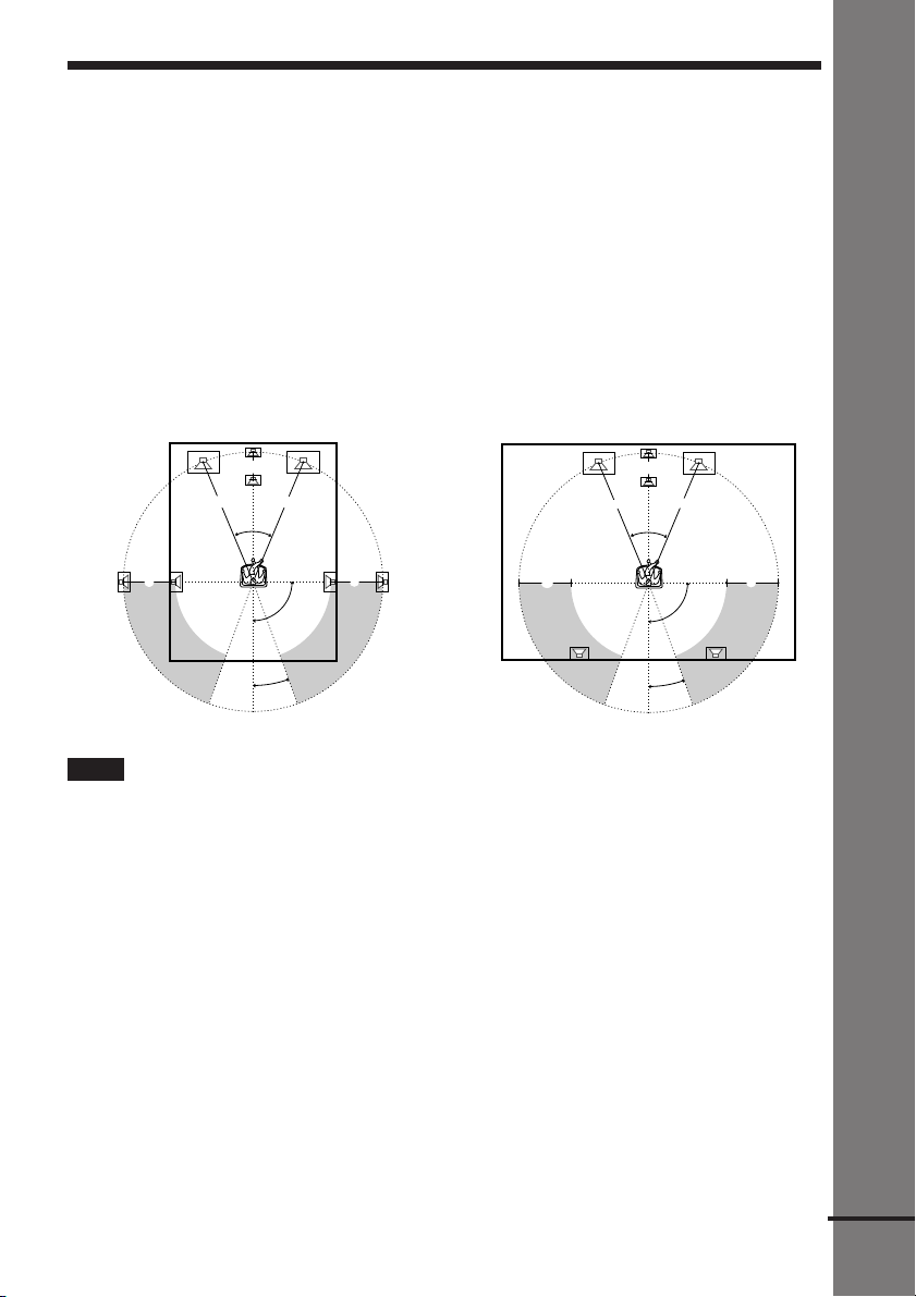
Speaker Setup
For the best possible surround sound, all the speakers other than the subwoofer should be the
same distance from the listening position (A).
However, this receiver allows you to place the center speaker up to 1.5 meters (5.0 feet) closer
(B) and the rear speakers up to 4.5 meters (15.0 feet) closer (C) to the listening position.
The front speakers can be placed from 0.9 to 15.0 meters (3.0 to 50.0 feet) (A) from the
listening position.
You can place the subwoofer in any position.
You can place the rear speakers either behind you or to the side, depending on the shape of your
room, etc.
When the rear speakers are placed to the side
When the rear speakers are placed behind you
Getting Started
B
A A
45°
C
20°
C
90°
B
A A
45°
CC
90°
20°
Note
Do not place the center and rear speakers farther away from the listening position than the front speakers.
When color irregularity occurs on the TV screen
If speakers are installed too close, color irregularity may occur on the screen.
If color irregularity occurs…
Turn off the TV set once, then turn it on after 15 to 30 minutes.
If color irregularity occurs again…
Place speakers farther away from the TV set.
If color irregularity still occurs after performing the above…
Make sure that no magnetic object is nearby speakers. Color irregularity may occur as a result
of interaction between speakers and the magnetic object.
Examples of possible sources of magnetic interference include: magnetic latches on a TV stand,
healthcare devices, toys, etc.
continued
27
US
Page 28
Specifying the speaker parameters
To obtain the best possible surround sound, first specify the distance of the speakers from your
listening position, then set the balance and level. Use the test tone to adjust the speaker volumes
to the same level.
You may adjust the speaker parameters using SPEAKER SETUP in the setup display (page 80).
C/X/x/c/ENTER
AMP MENU
To specify the size, distance, position and height of the speakers
1 Press AMP MENU repeatedly to display 9 SP. SETUP on the front panel display.
2 Sit in your listening position and select the item to be set using X/x.
• Items set in 9 SP. SETUP
–Size of 5 speakers (front L/R, center, rear L/R)
–with or without the center and rear L/R speakers and subwoofer
–Distance of the front, rear, and center speakers
–Position and height of the rear speakers
3 Set the parameter using C/c.
The selected parameter will appear on the front panel display.
4 Repeat Steps 2 and 3 to set other parameters in 9 SP. SETUP.
If you do not operate the remote for a few seconds, the parameter disappears from the
display and is stored in the receiver.
xSIZE
When you do not connect center or rear speakers or subwoofer, set the parameters for F.SP.,
C.SP., R.SP., and S.W. The default settings are underlined.
• F.SP. (front speaker)
LARGE: Normally select this.
–
–SMALL: Select this if the small speakers are used for the front speaker.
• C.SP. (center speaker)
LARGE: Normally select this.
–
–SMALL: Select this if the small speaker is used for the center speaker.
–NO: Select this if no center speaker is used.
US
28
Page 29
• R.SP. (rear speakers)
LARGE: Normally select this. Specify the position and height to implement the Digital
–
Cinema Surround modes in the sound field (page 55) properly.
–SMALL: Select this if the small speakers are used for the rear speaker. Specify the position
and height to implement the Digital Cinema Surround modes in the sound field (page 55)
properly.
–NO: Select this if no rear speakers are used.
• S.W. (subwoofer)
YES: Select this if the subwoofer is used.
–
–NO: Select this if no subwoofer is used.
xDISTANCE
You can vary the distance of each speaker as follows. The default settings are underlined.
• F. D. 5.1 m (17 ft) (front speakers distance)
Front speaker distance can be set in 0.3 meters (1 foot) steps from 0.9 to 15.0 meters (3 to 50
feet).
5.1 m (17 ft) (center speaker distance)
• C. D.
Center speaker distance can be set in 0.3 meters (1 foot) steps from a distance equal to the
front speaker distance to a distance 1.5 meters (5 feet) closer to your listening position.
3.6 m (12 ft) (rear speakers distance)
• R. D.
Rear speaker distance can be set in 0.3 meters (1 foot) steps from a distance equal to the front
speaker distance to a distance 4.5 meters (15 feet) closer to your listening position.
Note
If each of the front or rear speakers are not placed an equal distance from your listening position, set the distance
of the closest speaker.
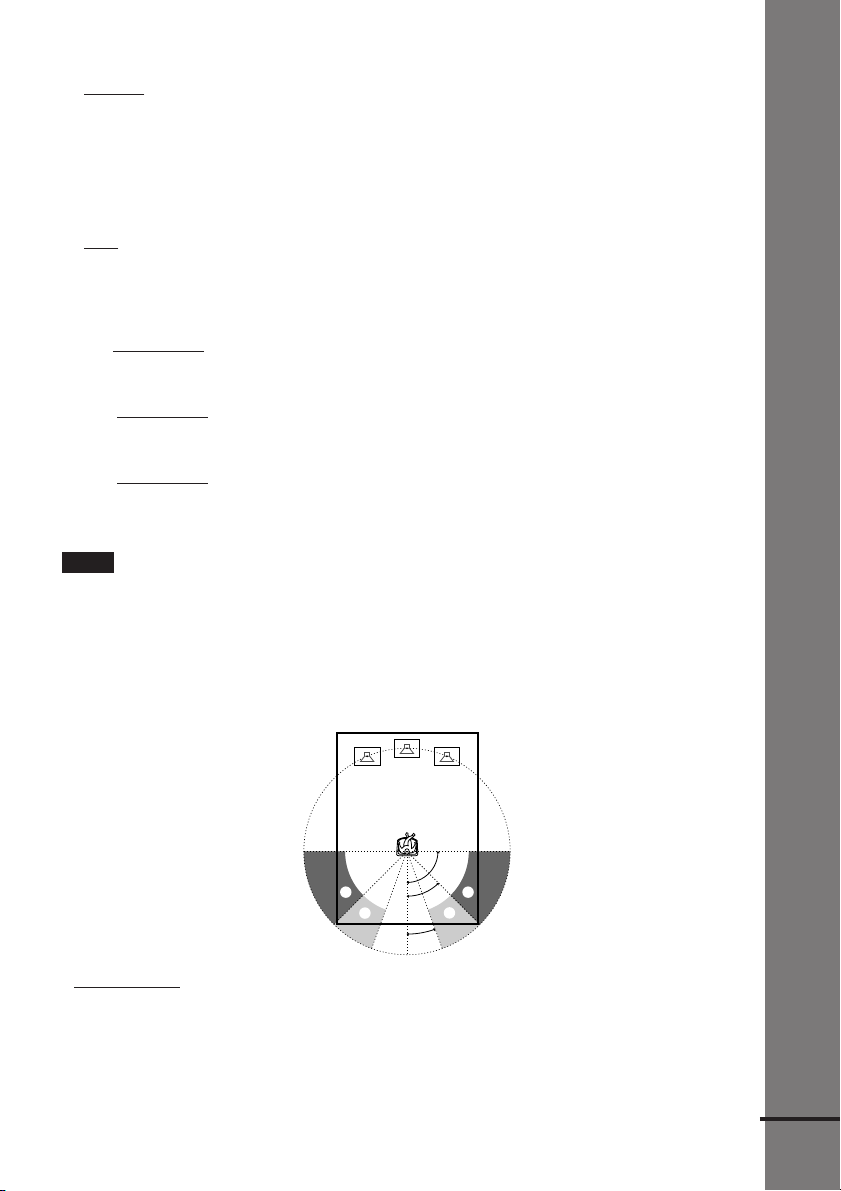
Specifying the rear speaker position and height
If you select anything other than “NO” in “R.SP.,” specify the position and height of the rear
speakers. The default settings are underlined.
Getting Started
Position diagram
90
AA
45
BB
20
• R. P. BEHIND
Select this if the rear speakers are located in the section B.
• R. P. SIDE
Select this if the rear speakers are located in the section A.
continued
29
US
Page 30

Height diagram
CC
60
DD
30
• R. H. LOW
Select this if the rear speakers are located in section D.
• R. H. HIGH
Select this if the rear speakers are located in section C.
These parameters are not available when “R.SP.” is set to “NO”.
To specify the balance and level of the speakers
1 Press AMP MENU repeatedly to display 9 LEVEL on the front panel display.
2 Use X/x to select T.TONE and use C/c to set T.TONE to ON.
You will hear the test tone from each speaker in sequence.
3 Sit in your listening position and select the item to be adjusted using X/x.
• Items adjusted in 9 LEVEL
–Balance of the front and rear speakers
–Volume level of the center and rear speakers and subwoofer
4 Adjust the volume level so that the volume of the test tone from each speaker sounds the
same using C/c.
The adjusted value will appear on the front panel display.
5 Repeat Steps 3 and 4 to adjust other parameters in 9 LEVEL.
If you do not operate the remote for a few seconds, the value disappears from the display
and is stored in the receiver.
6 Use X/x to select T.TONE and use C/c to set T.TONE to OFF.
xBALANCE
You can vary the balance of each speaker as follows. The default settings are underlined.
• F. ___I___
Adjust the balance between the front left and right speakers (You can adjust from center,
6 steps left or right).
• R. ___I___
Adjust the balance between the rear left and right speakers (You can adjust from center,
6 steps left or right).
xLEVEL
You can vary the level of each speaker as follows. The default settings are underlined.
• C. LEVEL (
Adjust the level of the center speaker (You can adjust from –10 dB to +10 dB in 1 dB steps.).
• R. LEVEL (
Adjust the level of the rear speakers (You can adjust from –10 dB to +10 dB in 1 dB steps.).
• S.W. LEV (
US
Adjust the level of the subwoofer (You can adjust from –10 dB to +10 dB in 1 dB steps.).
30
center (front speakers)
center (rear speakers)
0 dB) (center speaker level)
0 dB) (rear speakers level)
0 dB) (subwoofer level)
Page 31

• D.COMP. (Compressing the dynamic range of the sound)
You can compress the dynamic range of the sound. Using this function, you can listen to
sound at low volumes easily in the middle of the night. The compression function works only
when you play a disc recorded with Dolby Digital.
OFF: Audio is played back as it was recorded.
–
–ON: Audio is played back with the dynamic range compressed just as the recording engineer
intended.
Notes
• When you select an item, the sound cuts off for a moment.
• Depending on the settings of other speakers, the subwoofer may output excessive sound.
To adjust the volume of all the speakers at one time
Use the VOLUME control.
Other AMP MENU settings
You can control the brightness of the front panel display, clear the preset stations and the station
names, and set the speaker parameters back to the default setting. Press AMP MENU repeatedly
to display 9 CUSTOMIZE. Use X/x to select the following items.
xDIMMER
You can change the brightness of the front panel display (fluorescent tube and LED indicator)
by two steps.
xMEMO. CLR.
• N (No): Skip back to previous menu.
• Y (Yes): If you select Y by pressing ENTER, “Really? N” and “Really? Y” appears.
If you select “Really? Y,” by pressing ENTER, “ALL CLEAR!” is displayed and all settings
such as preset stations and station names will be cleared, and speaker parameters will be reset
to their default settings.
Getting Started
This receiver incorporates with Dolby Pro Logic II which has movie mode and music mode,
and the receiver can reproduce the 2 channel sound in 5.1 channel through Dolby Pro Logic II.
When the Sound Field is set to “AUTO DECODING*” or “NORMAL SURROUND,” you can
select the type of decoding for 2 channel source. Press AMP MENU repeatedly to display
92CH MODE. Use X/x to select the following items.
* The selected decoding mode is applied only when the Dolby Digital [Lt/Rt] signal is input.
x2CH MODE
• PLII MOVIE (Pro Logic II Movie): Performs the Pro Logic II movie mode decoding. This
setting is ideal for the movies encoded in Dolby Surround. Besides, this mode can reproduce
the sound in 5.1 channel when watching the videos of old movies or in the dubbed language.
• PLII MUSIC (Pro Logic II Music): Performs the Pro Logic II music mode decoding. This
setting is ideal for the normal stereo sources, such as CDs.
• PRO LOGIC: Performs the Pro Logic decoding. The source recorded in 2 channel is decoded
into 4 channels.
Note
Dolby Pro Logic II does not function for DTS or MPEG format signals or Super Audio CD.
31
US
Page 32

Presetting Radio Stations
You can preset 20 stations for FM and 10 stations for AM.
Before tuning, make sure to turn down the volume to minimum.
[/1
Scroll key, </>
CH +/–
ENTER
1 Press </> repeatedly until “<TUNER>” appears in the remote’s display.
2 Move the cursor (c) to “BAND” by using the Scroll key, then press the Scroll
key repeatedly until the band you want appears on the front panel display.
Every time you press the Scroll key, the band changes to AM or FM alternately.
m/M
3 Press and hold m or M until the frequency indication starts to change,
then release.
Scanning stops when the receiver tunes in a station. “TUNED” and “ST” (for stereo
program) appear on the front panel display.
FM AM
TUNED ST
MHz
AUTO
4 Move the cursor (c) to “MEMORY” by using the Scroll key, then press the
Scroll key.
A preset number appears on the front panel display.
FM
TUNED ST
MHz
5 Press CH + or – to select the preset number you want.
TUNED ST
MHz
32
FM
US
Page 33

6 Press ENTER.
The station is stored.
v
FM
7 Repeat 1 to 6 to store other stations.
To tune in a station with a weak signal
Press m or M repeatedly in 3 to tune in the station manually.
To change the preset number
Start over from 1.
To change the AM tuning interval
The AM tuning interval is factory set to 9 kHz (10 kHz in some areas).
To change the AM tuning interval, tune in any AM station first, then turn off the receiver by
pressing [/1 on the remote. While holding down x (on the receiver), turn on the power using
the remote. When you change the interval, AM preset stations will be erased.
To reset the interval, repeat the same procedure.
TUNED ST
MHz
Getting Started
33
US
Page 34

Playing Discs
Playing Discs
Depending on the DVD or VIDEO CD,
some operations may be different or
restricted.
Refer to the operating instructions supplied
with your disc.
POWER
STANDBY indicator
Connect
headphones
DISC 1-5
AHx
+
–
DISC SKIP
Adjust the volume
[/1
xH
4 Press A on the receiver, and
place a disc on the disc tray.
The receiver automatically turns on
and the STANDBY indicator turns off.
With the playback side facing down
Disc number
5 To place other discs, press DISC
SKIP and place the discs in the
order you want to play.
Each time you press the button, the
disc tray turns and you can place the
discs in the empty disc compartments.
The receiver plays the disc in front of
you first.
6 Press H.
The disc tray closes, and the receiver
starts playback (continuous play).
To playback other discs, press DISC
SKIP or DISC 1-DISC 5.
Adjust the volume on the receiver.
1 Turn on your TV.
2 Switch the input selector on the TV
to this receiver.
3 Press POWER on the receiver.
The receiver enters standby mode and
the STANDBY indicator lights up in
red.
US
34
After following Step 6
Depending on the disc, a menu may appear
on the TV screen. You can play the disc
interactively by following the instructions
on the menu. DVD (page 38), VIDEO CD
(page 38).
To turn on the receiver
Press POWER on the receiver. The receiver
enters standby mode and the STANDBY
indicator lights up in red. Press [/1 on the
remote. The receiver turns on and the
STANDBY indicator turns off. In standby
mode, the receiver also turns on by pressing
A, DISC 1-5, or FUNCTION –/+ on the
receiver or by pressing H.
Page 35

To turn off the receiver
Press [/1 on the remote. The receiver enters
standby mode and the STANDBY indicator
lights up in red. To turn off the receiver
completely, press POWER on the receiver.
While playing a disc, do not turn off the
receiver by pressing POWER. Doing so may
cancel the menu settings. When you turn off
the receiver, first press x to stop playback
and then press [/1 on the remote.
To select a disc by using the remote’s
display
Press </> until “<DISC>” appears in the
remote’s display, and move the cursor (c) to
“DISC 1 –DISC5” or “DISC SKIP” by
using the Scroll key, then press the Scroll
key.
On Auto-Function
z
If a disc is already inserted to any disc tray, you can
play it back simply by pressing the H or its
corresponding DISC 1-DISC 5, even if the previous
music source was not a DVD. The function changes
to DVD and playback starts (Auto-Function).
However, if Program Play is on, you can only start
playback by pressing the H.
z On the DISC indicators
The DISC indicators change as follows:
– light blue: the disc tray is chosen, or the disc is
being play backed.
– off: there is no disc.
– dark blue: a disc is placed on the disc tray, however,
the disc tray is not chosen. Before the disc
existence is checked, the indicators are in dark
blue.
Saving the power in standby mode
after turn on the receiver
Press [/1 on the remote once.
z While the receiver is in standby mode, the
STANDBY indicator on the receiver lights up.
Additional operations
./>
H
X
To Operation
Stop Press x.
Pause Press X.
Resume play after Press X or H.
pause
Go to the next chapter, Press >.
track, or scene in
continuous play mode
Go back to the Press ..
preceding chapter, track,
or scene in continuous
play mode
Stop play and remove Press A on the
the disc receiver.
Mute the sound Press MUTING. To
cancel muting, press it
again or turn up the
volume.
Change a disc while Press EX-CHANGE on
playing another disc the receiver.
Play the desired disc Press DISC 1-DISC 5
directly on the receiver.
x
MUTING
Playing Discs
To cancel standby mode
Press [/1 on the remote once.
Notes
• Do not push the disc tray when closing it. Press A
on the receiver to close the disc tray.
• If there is no disc in any disc tray, “NO DISC”
appears on the front display.
35
US
Page 36

Replacing Discs While
Playing a Disc
You can open the disc tray while playing a
disc so that you can check what discs are to
be played next and replace discs without
interrupting play of the current disc.
EX-CHANGE
+
–
DISC SKIP
1 Press EX-CHANGE.
The disc tray opens and two disc
compartments appear. Even if the
receiver is playing a disc, it doesn’t
stop playing.
2 Replace discs in the
compartments with new ones.
The receiver plays the disc on the left
side compartment after the current
disc, and then the one on the right side
compartment.
Note
Do not push the disc tray to close it in Step 5, as you
may damage the receiver.
3 Press DISC SKIP.
The disc tray turns and other two disc
compartments appear.
4 Replace discs in the
compartments with new ones.
5 Press EX-CHANGE.
The disc tray closes.
US
36
Page 37

Resuming Playback from
the Point Where You
Stopped the Disc
(Resume Play)
When you stop the disc, the receiver
remembers the point where you pressed x
and “RESUME” appears on the front panel
display. As long as you do not remove the
disc, Resume Play will work even if the
receiver enters standby mode by pressing
[/1.
Hx
z To play from the beginning of the disc, press x
twice, then press H.
Notes
• Depending on where you stopped the disc, the
receiver may not resume playback from exactly the
same point.
• The point where you stopped playing is cleared
when:
– you turn the power off by pressing POWER on
the receiver.
– you change the play mode.
– you change the setting on the Setup Menu.
Playing Discs
1 While playing a disc, press x to
stop playback.
“RESUME” appears on the front panel
display, so you can restart the disc
from the point where you stopped the
disc.
If “RESUME” does not appear,
Resume Play is not available.
2 Press H.
The receiver starts playback from the
point where you stopped the disc in
Step 1.
37
US
Page 38

Using the DVD’s Menu
A DVD is divided into long sections of a
picture or a music feature called “titles.”
When you play a DVD which contains
several titles, you can select the title you
want using TOP MENU/GUIDE.
When you play DVDs that allow you to
select items such as the language for the
subtitles and the language for the sound,
select these items using AV MENU.
Playing VIDEO CDs with
PBC Functions (PBC Playback)
With PBC (Playback Control) functions,
you can enjoy simple interactive operations,
search functions, and other such operations.
PBC playback allows you to play VIDEO
CDs interactively by following the menu on
the TV screen.
TOP MENU/
GUIDE
ENTER
C/X/x/c
AV MENU
1 Press TOP MENU/GUIDE or AV
MENU.
The disc’s menu appears on the TV
screen.
The contents of the menu vary from
disc to disc.
2 Press C/X/x/c to select the item
you want to play or change.
3 Press ENTER.
./>
H
ENTER
X/x
x
O RETURN/
EXIT
1 Start playing a VIDEO CD with PBC
functions.
The menu for your selection appears.
2 Select the item number you want
by pressing X/x.
3 Press ENTER.
4 Follow the instructions in the
menu for interactive operations.
Refer to the instructions supplied with
the disc, as the operating procedure
may differ according to the VIDEO
CD.
38
US
Page 39

To go back to the menu
Press O RETURN/EXIT.
z To play without using PBC, press ./>
while the receiver is stopped to select a track, then
press H or ENTER.
“Play without PBC” appears on the TV screen and
the receiver starts continuous play. You cannot play
still pictures such as a menu. To return to PBC
playback, press x twice, then press H.
Note
Depending on the VIDEO CD, “Press ENTER” in
Step 3 may appear as “Press SELECT” in the
instructions supplied with the disc. In this case, press
H.
Playing an MP3 Audio
Track
You can play back data CDs (CD-ROMs/
CD-Rs/CD-RWs) recorded in MP3 (MPEG1
Audio Layer 3) format.
1 Load a data disc recorded in MP3
into the receiver.
2 Press H.
The receiver starts to play the first
MP3 audio track in the first album on
the disc.
Note
The player can play MP3 audio tracks recorded in the
following sampling frequencies: 32 kHz, 44.1 kHz,
48 kHz.
Playing Discs
Selecting an album and track
ENTER
X/x/C/c
DVD
DISPLAY
1 Press DVD DISPLAY.
The Control Menu and disc name of
MP3 data disc appear.
ORETURN/
EXIT
continued
39
US
Page 40

2 Press X/x to select (ALBUM)
then press ENTER or c.
The list of albums contained in the disc
appears.
2:MP3
ROCK BEST HIT
KARAOKE
JAZZ
R&B
MY FAVORITE SONGS
CLASSICAL
SALSA OF CUBA
BOSSANOVA
3 Select an album you want to play using
X/x and press ENTER.
4 Select (TRACK) using X/x
and press ENTER.
The list of tracks contained in the
current album appears.
2:MP3
ROCK BEST HIT
HIGHWAY1.
2.
VIEW POINT
3.
MY CHILDREN
4.
DANCING
5.
GOOD TASTE
6.
DESTINATION
MARATHON
7.
8.
PLACE-KICK
9.
TAKE IT EASY
PORT TOWER
10.
When the list of all tracks or albums
cannot be displayed on the window, the
jump bar appears. Press c to select the
jump bar icon, and then scroll the jump
bar to display the rest of the list using X/
x.
Notes
• Only the letters in the alphabet and numbers can be
used for album or track names. Anything else is
displayed as “ ”.
• If the MP3 file you play back has an ID3 tag, the
ID3 tag information is displayed as a track name.
MP3
About MP3 audio tracks
You can play MP3 audio tracks on CDROMs, CD-Rs, or CD-RWs. However, the
discs must be recorded according to
ISO9660 level 1, level 2, or Joliet format for
the player to recognize the tracks. You can
also play discs recorded in Multi Session.
See the instructions of the CD-R/RW device
or recording software (not supplied) for
details on the recording format.
To play a Multi Session CD
This player can play Multi Session CDs
when an MP3 audio track is located in the
first session. Any subsequent MP3 audio
tracks, recorded in the later sessions, can
also be played back.
MP3
When audio tracks and images in music CD
format or video CD format are recorded in
the first session, only the first session will be
played back.
Notes
• If you put the extension “.MP3” to data not in MP3
format, the player cannot recognize the data
properly and will generate a loud noise which could
damage your speaker system.
• The player cannot play audio tracks in MP3PRO
format.
5 Select a track using X/x and press
ENTER.
The Selected track starts playing.
To return to the previous display
Press ORETURN/EXIT or C.
To turn off the display
Press DVD DISPLAY.
US
40
Page 41

Selecting the Play Mode
(All Discs, One Disc, or Album)
You can select the play mode that plays all
discs continuously, one disc, or album.
xALL/ONE/ALBUM
•
ALL: The receiver plays all discs in the
receiver consecutively in the order of the
disc slot number, and you can set Shuffle
Play or Repeat Play for all the discs.
• ONE: The receiver plays only the one disc
you have selected, and you can set Shuffle
Play or Repeat Play for 1 disc only.
• ALBUM (MP3 only): The receiver plays
tracks in the Album that is contained on a
MP3 disc, and you can set Shuffle Play or
Repeat Play for the Album. When the disc
except an MP3 disc is played, the receiver
plays the disc in ONE play mode.
To return to the previous display
Press ORETURN/EXIT or C.
Playing Discs
ENTER
X/x/c
DVD
DISPLAY
1 In stop mode, press DVD DISPLAY.
The Control Menu appears.
2 Press X/x to select
(PLAY MODE), then press ENTER
or c.
2:MP3
(
)
1 5
CONTINUE (ALL)
CONTINUE (ONE)
CONTINUE (ALBUM)
SHUFFLE (ALL)
SHUFFLE (ONE)
SHUFFLE (ALBUM)
PROGRAM
MP3
To turn off the display
Press DVD DISPLAY.
To select the play mode by using the
remote’s display
Press </> until “<PLAYER>” appears in the
remote’s display, and move the cursor (c) to
“PLAY MODE” by using the Scroll key,
then press the Scroll key. Each time you
press the Scroll key, the play mode changes.
41
US
Page 42

Creating Your Own
Program (Program Play)
You can play the contents of a disc in the
order you want by arranging the order of the
tracks on the disc to create your own
program. You can program up to 25 tracks.
H
ENTER
X/x/c
DVD
DISPLAY
1 In stop mode, press DVD DISPLAY.
The Control Menu appears.
2 Press X/x to select
(PLAY MODE), then press ENTER
or c.
3 Press X/x to select “PROGRAM,”
then press ENTER.
The program menu appears on the TV
screen.
Program
1
2
3
4
5
6
7
8
9
10
4 Press c, then press X/x to select
the disc.
Program
1
Disc
2
DISC1(CD)
3
DISC2(CD)
4
DISC3(CD)
5
DISC4(CD)
6
DISC5(CD)
7
8
9
10
5 Press c.
The cursor moves to the track (in this
case, “DISC1(CD)”). Before
programming the MP3 tracks, it is
required to select the album.
Program
1
Disc
2
DISC1(CD)
Track
3
DISC2(CD)
ALL TRACKS
4
DISC3(CD)
1 TRACK1
5
DISC4(CD)
2 TRACK2
6
DISC5(CD)
3 TRACK3
7
4 TRACK4
8
5 TRACK5
9
6 TRACK6
10
7 TRACK7
8 TRACK8
9 TRACK9
When the list of all tracks or albums
cannot be displayed on the window,
the jump bar appears. Press c to select
the jump bar icon, and then scroll the
jump bar to display the rest of the list
using X/x.
6 Select the track you want to
program.
For example, select track “7.”
Program
1
Disc
2
DISC1(CD)
Track
3
DISC2(CD)
ALL TRACKS
4
DISC3(CD)
1 TRACK1
5
DISC4(CD)
2 TRACK2
6
DISC5(CD)
3 TRACK3
7
4 TRACK4
8
5 TRACK5
9
10
6 TRACK6
7 TRACK7
8 TRACK8
9 TRACK9
42
US
Page 43

7 Press X/x to select “7” then press
ENTER.
Program
1 DISC1(CD)–TRACK7
2
3
4
5
6
7
8
9
10
To select the Program Play mode by
using the remote’s display
Press </> until “<PLAYER>” appears in the
remote’s display, and move the cursor (c) to
“PLAY MODE” by using the Scroll key,
then press the Scroll key until the
PROGRAM menu appears on the TV
screen.
You can do Repeat Play of the programmed
z
tracks. Press DVD DISPLAY, select
(REPEAT) by pressing X/x, and press ENTER, then
select the Repeat Play setting (page 45).
Playing Discs
8 To program other tracks, repeat
Steps 4 to 7.
The programmed tracks are displayed
in the selected order.
9 Press H to start Program Play.
Program Play begins.
When the program ends, you can
restart the same program again by
pressing H.
To cancel Program Play
Press DVD DISPLAY, select
(PLAY MODE) by pressing X/x, and press
ENTER, then select another play mode by
pressing X/x.
To turn off the program menu
In stop mode, press DVD DISPLAY to turn
off the program menu.
To cancel the programmed order
In Step 2, press </> until “<NUM>” appears
in the remote’s display, and move the cursor
(c) to “CLEAR” by using the Scroll key,
then press the Scroll key. The last program
is canceled one by one.
Notes
• The number and name of tracks displayed on the
TV screen are the recorded data on a disc.
• This Program Play function is not available for
DVDs.
43
US
Page 44

Playing in random order
(Shuffle Play)
You can have the receiver “shuffle” tracks
and play them in random order. Subsequent
“shuffling” may produce a different playing
order. You can also select the all discs
shuffle, one disc shuffle, or album shuffle
(MP3 only).
ENTER
X/x/c
DVD
DISPLAY
To cancel Shuffle Play
In stop mode, press DVD DISPLAY, select
(PLAY MODE) by pressing X/x,
and press ENTER, then select another play
mode by pressing X/x.
To turn off the display
Press DVD DISPLAY.
To select the Shuffle Play mode by
using the remote’s display
Press </> until “<PLAYER>” appears in the
remote’s display, and move the cursor (c) to
“PLAY MODE” by using the Scroll key,
then press the Scroll key until the Shuffle
Play mode you want appears in the front
panel display.
1 Press DVD DISPLAY.
The Control Menu appears.
2 Press X/x to select
(PLAY MODE), then press ENTER
or c.
2:MP3
CONTINUE (ALL)
CONTINUE (ONE)
CONTINUE (ALBUM)
SHUFFLE (ALL)
SHUFFLE (ONE)
SHUFFLE (ALBUM)
PROGRAM
3 Select “SHUFFLE (ALL),”
“SHUFFLE (ONE),” or “SHUFFLE
(ALBUM)” using X/x and press
ENTER.
The selected shuffle play begins.
US
44
(
)
1 5
MP3
Page 45

Playing repeatedly (Repeat
Play)
You can play all the titles/tracks or a single
title/chapter/track on a disc.
In Shuffle or Program Play mode, the
receiver repeats tracks in the shuffled or
programmed order.
You cannot perform Repeat Play during
PBC playback of VIDEO CDs (page 38).
H
ENTER
X/x
DVD DISPLAY
1 Press DVD DISPLAY.
The Control Menu appears.
2 Press X/x to select
(REPEAT), then press ENTER.
If you do not select “OFF,” the
indicator of the “REPEAT” lights in
green.
3 Select the Repeat Play setting.
1:DVD
1 2 ( 2 7 ) MAKING SCENE
)
1 8 ( 3 4
T
1 : 3 2 : 5 5
OFF
ALL
TITLE
CHAPTER
When playing a DVD
•
OFF: does not play repeatedly.
• ALL: repeats all the titles (except
SHUFFLE (ALL)).
• TITLE: repeats the current title on a disc.
• CHAPTER: repeats the current chapter
(except SHUFFLE (ALL)).
When playing a VIDEO CD/Super
Audio CD/CD/MP3 and when Program
Playing Discs
Play is set to OFF
OFF: does not play repeatedly.
•
• ALL: repeats all the tracks on the disc, or
repeats the current album (MP3 only)
(except SHUFFLE (ALL)).
• TRACK: repeats the current track.
When Program Play is set to ON
OFF: does not play repeatedly.
•
• ALL: repeats Program Play.
To cancel Repeat Play
Press DVD DISPLAY, select
(REPEAT) by pressing X/x, and press
ENTER, then select “OFF.”
To turn off the display
Press DVD DISPLAY.
To select the Repeat Play mode by
using the remote’s display
Press </> until “<PLAYER>” appears in the
remote’s display, and move the cursor (c) to
“REPEAT” by using the Scroll key, then
press the Scroll key until the Repeat Play
mode you want appears in the front panel
display.
You can set Repeat Play during stop
z
mode
After selecting the “REPEAT” item, press H.
DVD
The receiver starts Repeat Play.
Note
You can perform Repeat play for DVD titles that
contain chapters.
45
US
Page 46

Searching for a Scene
Searching for a Particular
Point on a Disc (Scan, Slow-
motion Play)
You can locate a particular point on a disc
quickly by monitoring the picture or playing
back slowly.
m/M
H
Notes
• Depending on the DVD/VIDEO CD, you may not
be able to do some of the operations described.
• This function does not work when you play an
MP3 disc.
Locating a point quickly by playing
a disc in fast forward or fast
reverse (Scan)
Press m or M while playing a disc.
When you find the point you want, press
H to return to normal speed.\
To change the scan speed (DVD/
VIDEO CD/Super Audio CD only)
Each time you press m or M during
scan, the playback speed changes. Two
speeds are available. With each press, the
indication changes as follows:
Playback direction
FF1M t FF2M
t
Opposite direction
FR1m t FR2m
t
The FF2M/FR2m playback speed is
faster than FF1M/FR1m.
Watching frame by frame (Slowmotion play)
You can use this function only for DVDs or
VIDEO CDs. Press m or M when the
system is in the pause mode. To return to
normal speed, press H.
Each time you press m or M during
Slow-motion play, the playback speed
changes. Two speeds are available. With
each press, the indication changes as
follows:
Playback direction
SLOW 2M t SLOW 1M
t
46
US
Opposite direction (DVD only)
SLOW 2m t SLOW 1m
t
The SLOW 2M/SLOW 2m playback
speed is slower than SLOW 1M/SLOW
1m.
Page 47

Searching for a Title/
Chapter/Track/Index/
Album
You can search a title (DVD), chapter
(DVD), track (CD, VIDEO CD, Super
Audio CD, MP3), index (VIDEO CD, Super
Audio CD), and album (MP3). As titles,
tracks and albums are assigned unique
names on the disc, you can select the desired
one from the Control Menu. Also chapters
and indexes are assigned unique numbers on
the disc, so you select the desired one by
entering its number. Or you can search a
particular point using the time code. (TIME
SEARCH)
xWhen playing a DVD
(TITLE)
xWhen playing a VIDEO CD
(TRACK)
xWhen playing a Super Audio
CD
(TRACK)
xWhen playing a CD
(TRACK)
xWhen playing an MP3
(ALBUM) or
(TRACK)
Example: when you select
(TRACK)
The list of tracks contained in the disc
appears.
Searching for a Scene
Scroll key,
</>
ENTER
X/x/c
DVD DISPLAY
Searching for a title/track/album
1 Press DVD DISPLAY.
The Control Menu appears.
2 Press X/x to select the search method,
then press ENTER.
HIGHWAY1.
2.
VIEW POINT
3.
MY CHILDREN
4.
DANCING
5.
GOOD TASTE
6.
DESTINATION
MARATHON
7.
8.
PLACE-KICK
9.
TAKE IT EASY
PORT TOWER
10.
CD
When the list of all tracks or albums
cannot be displayed on the window,
the jump bar appears. Press c to select
the jump bar icon, and then scroll the
jump bar to display the rest of the list
using X/x.
2.
VIEW POINT
3.
MY CHILDREN
4.
DANCING
5.
GOOD TASTE
6.
DESTINATION
7.
MARATHON
8.
PLACE-KICK
9.
TAKE IT EASY
PORT TOWER
10.
11.STANDARD
CD
3 Press X/x to select the desired track,
then press ENTER.
The receiver starts playback from the
selected track.
47
US
Page 48

Searching for a chapter/index
1 Press DVD DISPLAY.
The Control Menu appears.
2 Press X/x to select the search method.
xWhen playing a DVD
(CHAPTER)
xWhen playing a VIDEO CD
(INDEX)
xWhen playing a Super Audio
CD
(INDEX)
4 Press X/x to select the chapter or index
number you want to search.
If you make a mistake
Cancel the number by using the Scroll
key, then select another number.
To cancel the number, press </> until
“<NUM>” appears in the remote’s
display, and move the cursor (c) to
“CLEAR” by using the Scroll key,
then press the Scroll key.
5 Press ENTER.
The receiver starts playback from the
selected number.
Example: when you select
(CHAPTER)
“** (**)” is selected (** refers to a
number).
The number in parentheses indicates
the total number of titles, chapters,
tracks, or indexes.
DVD
1 2 ( 2 7 ) MAKING SCENE
)
1 8 ( 3 4
T
1 : 3 2 : 5 5
3 Press ENTER.
“** (**)” changes to “— (**)”.
DVD
1 2 ( 2 7 ) MAKING SCENE
)
– – ( 3 4
T
1 : 3 2 : 5 5
To turn off the Control Menu
Press DVD DISPLAY repeatedly until the
Control Menu is turned off.
DVD
DVD
48
US
Page 49

To search for a particular point
using the time code (TIME SEARCH)
1 In Step 2, select (TIME).
“T **:**:**” (playing time of the
current title or track) is selected.
2 Press ENTER.
“T **:**:**” changes to “T --:--:--.”
3 Input the time code. Press </> to select
“<NUM>” and select the time code
number by using the scroll key, then
press the Scroll key.
Example: To find the desired point at
2 hours, 10 minutes, and 20 seconds
after the beginning.
Select “2” and press the Scroll key.
r
Select “1” and press the Scroll key.
r
Select “0” and press the Scroll key.
r
Select “2” and press the Scroll key.
r
Select “0” and press the Scroll key.
Notes
• The title, chapter or track number displayed on the
TV screen is the recorded data on the disc.
• You cannot search a scene of a VIDEO CD.
Searching for a Scene
49
US
Page 50

Viewing Information About the Disc
Viewing the Playing Time
and Remaining Time on
When playing a DVD
Playing time and number of the current title
TITLE TRACK CHAPTER INDEX TUNEDH MONOM STS
the Front Panel Display
You can check information about the disc,
such as the remaining time, total number of
titles of a DVD, or tracks of a Super Audio
CD, CD, VIDEO CD, or MP3 using the
front panel display (page 11).
Scroll key,
</>
1 Press </> repeatedly until
“<PLAYER>” appears in the
remote’s display, then move the
cursor (c) to “TIME” by using the
Scroll key.
Remaining time of the
current title
TITLE TRACK CHAPTER INDEX TUNEDH MONOM STS
Playing time and number
of the current chapter
TITLE TRACK CHAPTER INDEX TUNEDH MONOM STS
Remaining time of the
current chapter
TITLE TRACK CHAPTER INDEX TUNEDH MONOM STS
Title name
TITLE TRACK CHAPTER INDEX TUNEDH MONOMSTS
When playing a VIDEO CD (without
PBC functions), Super Audio CD or
CD
Playing time and current track number
TITLE TRACK CHAPTER INDEX TUNEDH MONOM ST S
Remaining time of the
current track
TITLE TRACK CHAPTER INDEX TUNEDH MONOM ST S
Playing time of the disc
TITLE TRACK CHAPTER INDEX TUNEDH MONOM ST S
2 Press the Scroll key.
Each time you press the Scroll key
while playing the disc, the display
changes as shown in the following
charts.
US
50
Remaining time of the
disc
TITLE TRACK CHAPTER INDEX TUNEDH MONOM ST S
Track name
TITLE TRACK CHAPTER INDEX TUNEDH MONOMSTS
Page 51

When playing an MP3
Playing time and current track number
TITLE TRACK CHAPTER TUNEDH MONOM STS
Checking the Playing
Time and Remaining Time
Remaining time of the
current track
TITLE TRACK CHAPTER TUNEDH MONOM STS
Track (file) name
TITLE TRACK CHAPTER INDEX TUNEDH MONOM ST S
Album (folder) name
TITLE TRACK CHAPTER INDEX TUNEDH MONOMSTS
Notes
• ID3 tag applies only to version 1.
• If the MP3 file you play back has an ID3 tag, the
ID3 tag information is displayed as a track (file)
name.
• The ID3 tag character codes comply with ASCII
and ISO standards. Joliet format discs can only be
displayed in ASCII. Incompatible characters will be
displayed as “ ”.
• In the following cases, elapsed playing time and
time of the track remaining may not be displayed
accurately.
– when an MP3 file of VBR (variable bit rate) is
played.
– during fast-forward/reverse.
z When playing VIDEO CDs with PBC functions,
the playing time are displayed.
z The playing time and remaining time of the
current chapter, title, track, scene, or disc will also
appear on your TV screen. See the following section
“Checking the Playing Time and Remaining Time”
for instructions on how to read this information.
Notes
• While playing Super Audio CD, the index indicator
does not appear on the front panel display.
• Depending on the type of disc being played and the
playing mode, the disc information may not be
displayed.
You can check the playing time and
remaining time of the current title, chapter,
or track, and the total playing time or
remaining time of the disc. You can also
check the DVD/CD/Super Audio CD text
and MP3 folder name/file name/ID3 tag
(only song title) recorded on the disc.
Scroll key,
</>
DVD
DISPLAY
1 Press DVD DISPLAY during
playback.
The Control Menu appears.
1:DVD
1 2 ( 2 7 ) MAKING SCENE
)
1 8 ( 3 4
T
1 : 3 2 : 5 5
Time information
DVD
Disc type
Viewing Information About the Disc
continued
51
US
Page 52

2 Change the time information.
Press </> repeatedly until
“<PLAYER>” appears in the
remote’s display, move the cursor
(c) to “TIME” by using the Scroll
key, then press the Scroll key.
Each press the Scroll key, the time
information changes. The display and
the kinds of time that you can change
depend on the disc you are playing.
xWhen playing a DVD
•T **:**:
Playing time of the current title
•T–**:**:
Remaining time of the current title
•C **:**:
Playing time of the current chapter
•C–**:**:
Remaining time of the current
chapter
xWhen playing a VIDEO CD
(with PBC functions)
•**:
Playing time of the current scene
**
**
**
**
**
To turn off the Control Menu
Press DVD DISPLAY repeatedly until the
Control Menu is turned off.
Notes
• Only letters of the alphabet can be displayed.
• Depending on the type of disc being played, the
receiver can only display a limited number of
characters. Also, depending on the disc, all text
characters are not displayed.
52
xWhen playing a VIDEO CD
(without PBC functions), Super
Audio CD or CD
•T **:
**
Playing time of the current track
•T–**:
**
Remaining time of the current
track
•D **:
**
Playing time of the current disc
•D–**:
**
Remaining time of the current disc
xWhen playing an MP3
•T **:
**
Playing time of the current track
•T–**:
**
Remaining time of the current
track
US
Page 53

Sound Adjustments
Changing the Sound
If a DVD is recorded with multilingual
tracks, you can select the language you want
while playing the DVD.
If the DVD is recorded in multiple audio
formats (PCM, Dolby Digital, MPEG audio,
or DTS), you can select the audio format
you want while playing the DVD.
With stereo CDs or VIDEO CDs, you can
select the sound from the right or left channel
and listen to the sound of the selected channel
through both the right and left speakers. (In
this case, the sound loses its stereo effect.)
For example, when playing a disc containing
a song with the vocals on the right channel
and the instruments on the left channel, you
can select the left channel and hear only the
instruments from both speakers.
ENTER
X/x
DVD DISPLAY
1 Press DVD DISPLAY during
playback.
The Control Menu is displayed.
3 Press X/x to select the desired
audio signal.
xWhen playing a DVD
Depending on the DVD, the choice of
language varies.
When 4 digits are displayed, they
represent the language code. Refer to
the language code list on page 92 to
see which language the code
represents. When the same language is
displayed two or more times, the DVD
is recorded in multiple audio formats.
xWhen playing a VIDEO CD, or CD
The default setting is underlined.
•
STEREO: The standard stereo sound
• 1/L: The sound of the left channel
(monaural)
• 2/R: The sound of the right
channel (monaural)
xWhen playing a Super Audio CD
In stop mode, depending on the Super
Audio CD, the choice of settings varies.
• MULTI: The disc has multichannel playback area
• 2CH: The disc has the 2 channel
playback area.
• CD: When you want to play the
disc as a conventional CD.
Note
Not all discs give you the three choices above
when in Super Audio CD playback. It all
depends on the layer configuration of the
Super Audio CD to be played.
4 Press ENTER.
Sound Adjustments
2 Press X/x to select
(AUDIO), then press ENTER.
The options for AUDIO appear.
1:DVD
1 2 ( 2 7 ) MAKING SCENE
)
1 8 ( 3 4
T
1 : 3 2 : 5 5
1: ENGLISH
2: FRENCH
3: SPANISH
To turn off the Control Menu
Press DVD DISPLAY repeatedly until the
Control Menu is turned off.
DVD
continued
53
US
Page 54

To select the audio mode by using
the remote’s display
Press </> until “<PLAYER>” appears in the
remote’s display, and move the cursor (c) to
“AUDIO” by using the Scroll key, then press
the Scroll key. Each time you press the
Scroll key, the audio mode changes.
Notes
• For discs not in multiple audio format, you cannot
change the sound.
• During DVD playback, the sound may change
automatically.
The display examples are as follows:
• PCM (stereo)
PROGRAM FORMAT
PCM 48kHz 24bit
• Dolby Surround
PROGRAM FORMAT
DOLBY DIGITAL 2/0
DOLBY SURROUND
• Dolby Digital 5.1ch
Displaying the audio information of
the disc
When you select “AUDIO,” the channels
being played are displayed on the screen.
For example, in Dolby Digital format,
multiple signals ranging from monaural to
5.1 channel signals can be recorded on a
DVD. Depending on the DVD, the number
of recorded channels may differ.
Current audio format*
1:DVD
1 2 ( 2 7 ) MAKING SCENE
)
1 8 ( 3 4
T
1 : 3 2 : 5 5
1: ENGLISH
PROGRAM FORMAT
DOLBY DIGITAL 3/2.1
*“PCM,” “MPEG,” “DTS,” or “DOLBY
DIGITAL” is displayed.
For “DOLBY DIGITAL,” the channels in
the playing track are displayed numerically
as follows:
For Dolby Digital 5.1 ch:
Rear component 2
DVD
PROGRAM FORMAT
DOLBY DIGITAL 3/2.1
• DTS
PROGRAM FORMAT
DTS 3/2.1
Notes
• When the signal contains rear signal components
such as LS, RS, or S, the surround effect is
enhanced.
• If you play MPEG AUDIO sound tracks, the
receiver outputs PCM (stereo) signals.
Front component 2 +
Center component 1
US
54
DOLBY DIGITAL
3 / 2 . 1
LFE (Low Frequency
Effect) component 1
Page 55

Automatically decoding
the input audio signal (Auto
Decoding)
The auto decoding function automatically
detects the type of audio signal being input
(Dolby Digital, DTS, or standard 2 channel
stereo) and performs the proper decoding if
necessary. This mode presents the sound as
it was recorded/encoded, without adding any
effects (e.g. reverberation).
However, if there are no low frequency
signals (Dolby Digital LFE, etc.), it will
generate a low frequency signal for output to
the subwoofer.
SOUND
FIELD
Enjoying Surround Sound
You can take advantage of surround sound
simply by selecting one of the receiver’s
pre-programmed sound fields. They bring
the exciting and powerful sound of movie
theaters and concert halls into your home.
To select the sound field, press AUTO DEC,
2CH ST, or MODE on the receiver or
SOUND FIELD on the remote repeatedly
until the sound field you want appears on
the front panel display.
Sound field Display
Auto Decoding AUTO DECO.
Normal surround N.SURROUND
Cinema Studio EX A C.S.EX A*
Cinema Studio EX B C.S.EX B*
Cinema Studio EX C C.S.EX C*
Hall HALL
Jazz Club JAZZ CLUB
Live Concert L.CONCERT
Game GAME
2ch Stereo 2CH STEREO
Sound Adjustments
Press AUTO DEC on the receiver or
SOUND FIELD on the remote repeatedly
until “AUTO DECO.(AUTO DECODING)”
appears on the front panel display.
The auto format decode function is
activated.
* Use DCS Technology
About DCS (Digital Cinema Sound)
In the collaboration with Sony Pictures
Entertainment, Sony measured the sound
environment of their studios and integrated
the data of the measurement and Sony’s own
DSP (Digital Signal Processor) technology
to develop “Digital Cinema Sound”.
“Digital Cinema Sound” simulates in a
home theater an ideal movie theater sound
environment based on the preference of
movie director.
continued
55
US
Page 56

SOUND
FIELD
Enjoying movies with Cinema Studio
EX
Cinema Studio EX is ideal for enjoying the
movie software encoded with multi channel
format, such as the Dolby Digital DVD.
This mode reproduces the sound
characteristics of Sony Pictures
Entertainment’s studios.
Press MODE on the receiver or SOUND
FIELD on the remote repeatedly until
“C.S.EX A (or B, C)” appears on the front
panel display.
C.S.EX A (Cinema Studio EX A)
Reproduces the sound characteristics of the
Sony Pictures Entertainment “Cary Grant
Theater” cinema production studio. This is a
standard mode, great for watching most any
type of movie.
C.S.EX B (Cinema Studio EX B)
Reproduces the sound characteristics of the
Sony Pictures Entertainment “Kim Novak
Theater” cinema production studio. This
mode is ideal for watching science-fiction or
action movies with lots of sound effects.
C.S.EX C (Cinema Studio EX C)
Reproduces the sound characteristics of the
Sony Pictures Entertainment scoring stage.
This mode is ideal for watching musicals or
classic films where music is featured in the
soundtrack.
About Cinema Studio EX
Cinema Studio EX consists of the following
three elements.
• Virtual Multi Dimension
Creates 5 sets of virtual speakers
surrounding the listener from a single pair
of actual rear speakers.
• Screen Depth Matching
In a movie theater, sound seems to come
from inside the image reflected on the
movie screen. This element creates the
same sensation in your listening room by
shifting the sound of the front speakers
“into” the screen.
• Cinema Studio Reverberation
Reproduces the reverberations peculiar to a
movie theater.
Cinema Studio EX is the integrated mode
which operates these elements
simultaneously.
Notes
• The effects provided by the virtual speakers may
cause increased noise in the playback signal.
• When listening with sound fields that employ the
virtual speakers, you will not be able to hear any
sound coming directly from the rear speakers.
Selecting other sound fields
Press MODE on the receiver or SOUND
FIELD on the remote repeatedly until the
sound field you want appears on the front
panel display.
The current sound field appears on the front
panel display.
56
US
Page 57

N. SURROUND (Normal Surround)
Software with multi channel surround audio
signals is played back according to the way
it was recorded. Software with 2 channel
audio signals is decoded with Dolby Pro
Logic or Dolby Pro Logic II to create
surround effects (page 31).
HALL (Hall)
Reproduces the acoustics of a rectangular
concert hall.
JAZZ CLUB (Jazz Club)
Reproduces the acoustics of a jazz club.
L. CONCERT (Live Concert)
Reproduces the acoustics of a 300-seat live
concert.
GAME (Game)
Obtains maximum audio impact from video
game software.
HP . THEA TER (Headphone Theater)
When you connect your headphone to the
PHONES jack of the receiver, the
HEADPHONE THEATER mode allows you
to experience a theater like environment
while listening through a pair of
headphones. This mode is very effective
with 5.1 ch discrete signal sources like
Dolby Digital and DTS. Selecting any
Sound Field selections (except AUTO
DECODING or 2 CH STEREO) enables the
mode.
The receiver memorizes the last sound
z
field selected for each function mode (Sound
Field Link)
Whenever you select a function such as DVD or
TUNER, the sound field that was last applied to the
function is automatically applied again. For example,
if you listen to DVD with HALL as the sound field,
then change to another function, and then return to
DVD, HALL will be applied again. With the tuner,
sound fields are memorized separately for all preset
stations.
z You can identify the encoding format of
program software by looking at its packaging
– Dolby Digital discs are labelled with the logo.
– Dolby Surround encoded programs are labelled
with the logo.
– DTS Digital Surround discs are marked with DTS.
Note
When you play sound tracks with 96 kHz sampling
frequency, the output signals will be converted to
48 kHz (sampling frequency).
Sound Adjustments
To turn the surround effect off
Press AUTO DEC or 2CH ST on the
receiver or SOUND FIELD on the remote
repeatedly until “AUTO DECO.” or “2CH
STEREO” appears on the front panel
display.
57
US
Page 58

Using only the front
Adjusting the level
speakers (2 Channel Stereo)
SOUND
FIELD
Press 2CH ST on the receiver or
SOUND FIELD on the remote repeatedly
until “2CH STEREO” appears on the
front panel display.
This mode outputs the sound from the front
left and right speakers only. Standard 2
channel (stereo) sources completely bypass
the sound field processing. Multi channel
surround formats are downmixed to 2
channel.
Notes
• To listen to 2 channel (stereo) sources using the
front left and right speakers and a sub woofer, press
AUTO DEC on the receiver or SOUND FIELD on
the remote repeatedly to select “AUTO DECO.”
• Depending on the speaker setting, the sound is
output from the sub woofer.
parameters
The level menu contains parameters that let
you adjust the balance and speaker volumes
of each speaker (page 30).
C/X/x/c/ENTER
AMP MENU
1 Start playing a program source
encoded with multichannel
surround sound.
2 Press AMP MENU repeatedly.
9 LEVEL appears on the front panel
display.
3 Sit in your listening position and
select the item to be adjusted
using X/x.
58
4 Adjust the volume level using C/c.
The adjusted value will appear on the
front panel display. If you do not operate
the remote for a few seconds, the value
turns off and is stored in the receiver.
US
Page 59

Enjoying Movies
Changing the Angles
If various angles (multi-angles) for a scene
are recorded on the DVD, “ANGLE”
appears in the front panel display. This
means that you can change the viewing
angle.
For example, while playing a scene of a
train in motion, you can display the view
from either the front of the train, the left
window of the train, or from the right
window without having the train’s
movement interrupted.
ENTER
X/x/c
DVD
DISPLAY
3 Press c or ENTER.
The angle number changes to “-. ”
1:DVD
1 2 ( 2 7 ) MAKING SCENE
)
1 8 ( 3 4
T
1 : 3 2 : 5 5
)
– ( 9
DVD
4 Select the angle number using
X/x, then press ENTER.
The angle is changed to the selected
angle.
To turn off the Control Menu
Press DVD DISPLAY repeatedly until the
Control Menu is turned off.
To select the angle by using the
remote’s display
Press </> until “<PLAYER>” appears in the
remote’s display, and move the cursor (c) to
“ANGLE” by using the Scroll key, then
press the Scroll key. Each time you press the
Scroll key, the angle changes.
Enjoying Movies
1 Press DVD DISPLAY during
playback.
The Control Menu appears.
2 Press X/x to select
(ANGLE).
The angle number appears.
The number in parentheses indicates
the total number of angles.
1:DVD
1 2 ( 2 7 ) MAKING SCENE
)
1 8 ( 3 4
T
1 : 3 2 : 5 5
)
1
( 9
Note
Depending on the DVD, you may not be able to
change the angles, even if multi-angles are recorded
on the DVD.
DVD
US
59
Page 60

Displaying the Subtitles
If subtitles are recorded on the discs, you
can turn the subtitles on and off while
playing. If multilingual subtitles are
recorded on the disc, you can change the
subtitle language while playing, or turn the
subtitles on or off whenever you want. For
example, you can select the language you
want to practice and turn the subtitles on for
better understanding.
ENTER
X/x
DVD DISPLAY
3 Press X/x to select the language.
Depending on the DVD, the choice of
language varies.
When 4 digits are displayed, they
indicate the language code. Refer to
the language code list on page 92 to
see which language the code
represents.
4 Press ENTER.
To cancel the SUBTITLE setting
Select “OFF” in Step 3.
To turn off the Control Menu
Press DVD DISPLAY repeatedly until the
Control Menu is turned off.
To select the language by using the
remote’s display
Press </> until “<PLAYER>” appears in the
remote’s display, and move the cursor (c) to
“SUBTITLE” by using the Scroll key, then
press the Scroll key. Each time you press the
Scroll key, the language changes.
1 Press DVD DISPLAY during
playback.
The Control Menu appears.
2 Press X/x to select
(SUBTITLE), then press ENTER.
The options for SUBTITLE appear.
1:DVD
1 2 ( 2 7 ) MAKING SCENE
1 8 ( 3 4
T
OFF
1: ENGLISH
2: FRENCH
3: SPANISH
US
60
)
1 : 3 2 : 5 5
Note
Depending on the DVD, you may not be able to
change the subtitles even if multilingual subtitles are
recorded on it.
DVD
Page 61

Using Various Additional Functions
Locking Discs (CUSTOM
PARENTAL CONTROL, PARENTAL
CONTROL)
You can set two kinds of playback
restrictions for a disc.
• Custom Parental Control
You can set the playback restrictions so
that the receiver will not play inappropriate
discs.
• Parental Control
Playback of some DVDs can be limited
according to a predetermined level such as
the age of the users.
The same password is used for both Parental
Control and Custom Parental Control.
Custom Parental Control
You can set the same Custom Parental
Control password for up to 25 discs. When
you set the 26th disc, the playback
restriction of the disc for which you first set
the password is canceled.
To enter a 4-digit password by using
the Scroll key and </>
Press </> until “<NUM>” appears in the
remote’s display, select the number by using
the Scroll key, then press the Scroll key.
<
NUM>
* 1
* 2
* 3
1 Insert the disc you want to lock.
If the disc is playing, press x to stop
playback.
2 In stop mode, press DVD DISPLAY.
The Control Menu appears.
3 Press X/x to select (CUSTOM
PARENTAL CONTROL), then press
ENTER.
“CUSTOM PARENTAL CONTROL” is
selected.
1:DVD
1 2 ( 2 7 ) MAKING SCENE
)
1 8 ( 3 4
T
1 : 3 2 : 5 5
DVD
Using Various Additional Functions
Scroll key,
</>
ENTER
C/X/x
DVD DISPLAY
x
ORETURN/
EXIT
ON
PASSWORD
continued
61
US
Page 62

4 Press X/x to select “ON t,” then
press ENTER.
xWhen you have not entered a
password
The display for registering a new
password appears.
CUSTOM PARENTAL CONTROL
Enter a new 4-digit password,
ENTER
then press
.
If you make a mistake
Press O RETURN/EXIT, then start from
Step 3 again.
To turn off the Control Menu
Press DVD DISPLAY repeatedly until the
Control Menu is turned off.
To turn off the Custom Parental
Control function
1 In Step 4, select “OFF t,” then press
ENTER.
2 Enter your 4-digit password using the
Scroll key and </>.
Enter a 4-digit password by using the
Scroll key and </>.
The display for confirming the password
appears.
xWhen you have already
registered a password
The display for entering the password
appears.
CUSTOM PARENTAL CONTROL
Enter password, then press
ENTER
.
5 Enter or re-enter your 4-digit password
by using the Scroll key and </>.
“Custom parental control is set.” appears
and the screen returns to the Control
Menu display.
If you make a mistake entering
your password
Press C before you press the Scroll key
and input the correct number.
To change the password
1 In Step 4, press X/x to select
“PASSWORD t,” then press ENTER.
The display for entering the password
appears.
2 Enter your 4-digit password using the
Scroll key and </>.
3 Enter a new 4-digit password using the
Scroll key and </>.
4 To confirm your password, re-enter it
using the Scroll key and </>.
62
US
Page 63

Playing the disc for which Custom
Parental Control is set
1 Insert the disc for which Custom
Parental Control is set.
The CUSTOM PARENTAL CONTROL
display appears.
CUSTOM PARENTAL CONTROL
Custom parental control is already
set. To play, enter your password
ENTER
and press
.
2 Enter your 4-digit password using the
Scroll key and </>.
The receiver is ready for playback.
z If you forget your password, enter the 6-digit
number “199703” using the Scroll key and </> when
the CUSTOM PARENTAL CONTROL display asks
you for your password. The display will ask you to
enter a new 4-digit password.
Limiting playback for children
(Parental Control)
Playback of some DVDs can be limited
according to a predetermined level such as
the age of the users. The “Parental Control”
function allows you to set a playback
limitation level.
A scene that is limited is not played, or it is
replaced by a different scene.
Scroll key,
</>
H
ENTER
X/x
ORETURN/
EXIT
To enter a 4-digit password by using
the Scroll key and </>
Press </> until “<NUM>” appears in the
remote’s display, select the number by using
the Scroll key, then press the Scroll key.
DVD SETUP
Using Various Additional Functions
NUM>
<
* 1
* 2
* 3
continued
63
US
Page 64

1 In stop mode, press DVD SETUP.
The Setup Display appears.
2 Press X/x to select “CUSTOM SETUP,”
then press ENTER.
“CUSTOM SETUP” is displayed.
CUSTOM SETUP
PARENTAL CONTROL
TRACK SELECTION
OFF
3 Press X/x to select “PARENTAL
CONTROL t,” then press ENTER.
xIf you have not entered a
password
The display for registering a new
password appears.
CUSTOM SETUP
PARENTAL CONTROL
Enter a new 4-digit password,
ENTER
.
then press
Enter a 4-digit password using the Scroll
key and </>.
The display for confirming the password
appears.
xWhen you have already
registered a password
The display for entering the password
appears.
4 Enter or re-enter your password by
using the Scroll key and </>.
The display for setting the playback
limitation level and changing the
password appears.
CUSTOM SETUP
PARENTAL CONTROL
LEVEL: OFF
STANDARD:
CHANGE PASSWORD
USA
5 Press X/x to select “STANDARD,” then
press ENTER.
The selection items for “STANDARD”
are displayed.
CUSTOM SETUP
PARENTAL CONTROL
LEVEL:
STANDARD:
CHANGE PASSWORD
OTHERS
OFF
USA
6 Press X/x to select a geographic area
as the playback limitation level, then
press ENTER.
The area is selected.
If you select “OTHERS t,” select and
enter the standard code in the table on
page 66 using the Scroll key and </>.
7 Press X/x to select “LEVEL,” then
press ENTER.
The selection items for “LEVEL” are
displayed.
64
US
CUSTOM SETUP
PARENTAL CONTROL
Enter password, then press
ENTER
.
CUSTOM SETUP
PARENTAL CONTROL
STANDARD:
CHANGE PASSWORD
OFFLEVEL:
8:
NC17
7:
R
6:
5:
PG13
4:
PG
3:
2:
G
1:
Page 65

8 Select the level you want using X/x,
then press ENTER.
Parental Control setting is complete.
CUSTOM SETUP
PARENTAL CONTROL
STANDARD:
CHANGE PASSWORD
PG134:LEVEL:
USA
The lower the value, the more strict the
limitation.
If you make a mistake
Press O RETURN/EXIT to go back to the
previous screen.
To turn off the Setup Display
Press DVD SETUP repeatedly until the
Setup Display is turned off.
To turn off the Parental Control
function and play the DVD after
entering your password
Set “LEVEL” to “OFF” in Step 8.
To change the password
1 In Step 5, select “CHANGE
PASSWORD t” using x, then press
ENTER.
The display for entering the password
appears.
2 Follow Step 3 to enter a new password.
Playing the disc for which Parental
Control is set
1 Insert the disc and press H.
The PARENTAL CONTROL display
appears.
2 Enter your 4-digit password using the
Scroll key and </>.
The receiver starts playback.
z If you forget your password, remove the disc and
repeat Step 1 to 5 of “Limiting playback for
children.” When you are asked to enter your
password, enter “199703” using the Scroll key and
</>. The display will ask you to enter a new 4-digit
password. After you enter a new 4-digit password in
Step 3, replace the disc in the receiver and press H.
When the P ARENTAL CONTROL display appears,
enter your new password.
Notes
• When you play DVDs which do not have the
Parental Control function, playback cannot be
limited on this receiver.
• Depending on the DVD, you may be asked to
change the parental control level while playing the
disc. In this case, enter your password, then change
the level. If the Resume Play mode is cancelled, the
level returns to the original level.
Using Various Additional Functions
continued
65
US
Page 66

Area Code
Standard Code
number
Argentina 2044
Australia 2047
Austria 2046
Belgium 2057
Brazil 2070
Canada 2079
Chile 2090
China 2092
Denmark 2115
Finland 2165
France 2174
Germany 2109
Hong Kong 2219
India 2248
Indonesia 2238
Italy 2254
Japan 2276
Standard Code
number
Korea 2304
Malaysia 2363
Mexico 2362
Netherlands 2376
New Zealand 2390
Norway 2379
Pakistan 2427
Philippines 2424
Portugal 2436
Russia 2489
Singapore 2501
Spain 2149
Sweden 2499
Switzerland 2086
Taiwan 2543
Thailand 2528
United Kingdom 2184
66
US
Page 67

Other Operations
Controlling the other
units with the Supplied
Remote
By adjusting the remote signal, you can
control your TV, satellite receiver, VCR, or
cable tuner with the supplied remote.
Notes
• If you set a new manufacturer, the manufacturer
previously entered will be erased.
• When you replace the batteries of the remote, the
manufacturer settings may be reset to the default
(SONY) setting. Reset the appropriate code
number.
z Y ou can set the man ufacturer for your TV,
satellite receiver, VCR, or cable tuner
separately.
Setting the remote for controlling
the other units
The remote is preset at the factory to operate
Sony brand AV components. You can use the
Commander with other preset AV
components also.
If you are using the Commander with a
factory-set Sony component, skip the
following procedures.
To use with other units, you need to follow
the procedures to set the manufacturer codes
for each unit.
1 Press RM SETUP.
The Setup menu appears in the remote’s
display.
RM S E T
BACK L I GHT
TCON
TRRAS
ALL
CLEA
2 Move the cursor (c) to “RM SET” by
using the Scroll key, then press the
Scroll key.
RM S ET
><
TV
VID
EO
SAT
3 Move the cursor (c) to the desired
source by using the Scroll key, then
press the Scroll key.
AKER?M
ony
S
dm i r a lA
dm i r a lA
–1
–2
4 Move the cursor (c) to the desired
manufacturer name by using the Scroll
key, then press the Scroll key.
Other Operations
RM SETUP
Scroll key
Note
If more than one manufacturer name is listed, try
entering them one at a time until you find the one that
works with your unit.
67
US
Page 68

Controlling TVs with the remote
TV ?/1
TV VOL +/–
TV CH +/–
TV/VIDEO
WIDE
Controlling satellite receivers with
the remote
AV ?/1
Scroll key,
CH +/–
TOP MENU/
GUIDE
DVD
DISPLAY
</>
AV/MENU
ORETURN/
EXIT
Controlling the TV
You can control your TV using the buttons
below.
By pressing You can
TV [/1 Turn the TV on or off.
TV/VIDEO Switch the TV’s input source
between the TV and other input
sources.
TV VOL +/– adjust the TV volume.
TV CH +/– change the TV channel.
WIDE change the aspect ratio of your
TV.
Note
Depending on the TV, you may not be able to control
your TV or to use some of the buttons above.
Controlling the satellite receiver
Press </> repeatedly until “<SAT>” appears
in the remote’s display.
>SAT<
1
*
2
*
3
*
Move the cursor (c) to the desired item by
using the Scroll key, then press the Scroll
key.
Main items are listed as below. For details of
other items that appear in the remote’s
display, see the instructions of your satellite
receiver.
By selecting You can
1 – 9, 0, >10 Enter the number.
CH +, – Change the channel.
TV/SAT Switch the TV’s input source
JUMP Return to the previous channel.
between the TV and the satellite
receiver.
68
US
Page 69

z To enter 3-digit number at a time
1 Move the cursor (c) to “(- - -)” by using the Scroll
key.
>SAT<
0
*
/10
ENT
ER
*
(---)
*
2 Press the Scroll key.
3 Select the first digit number by using the Scroll
key and press the Scroll key.
>SAT<
--3
Controlling VCRs with the remote
AV ?/1
Scroll key, </>
CH +/–
H
X
DVD
DISPLAY
m/M
x
AV/MENU
4 Select the second digit number by using the Scroll
key and press the Scroll key.
5 Select the third digit number by using the Scroll
key and press the Scroll key.
Note
Depending on the satellite receiver, there may be an
item without a * mark. The operation does not work.
When “<SAT>” appears in the remote’s
display, you can also control your satellite
receiver using the buttons below.
By pressing You can
AV [/1 Turn the satellite receiver on or
off.
CH +/– Change the channel.
TOP MENU/ Display the program guide.
GUIDE
AV MENU Display the menu.
DVD DISPLAY Change the display.
O RETURN Return to the previous display
in the program guide or menu.
C/X/x/c/ Select the item in the program
ENTER guide or menu.
Note
Depending on the satellite receiver, you may not be
able to control your satellite receiver or to use some
of the buttons above.
Controlling the VCR
Press </> repeatedly until “<VIDEO>”
appears in the remote’s display.
>VIDEO<
*
1
2
*
*
3
Move the cursor (c) to the desired item by
using the Scroll key, then press the Scroll
key.
Main items are listed as below. For details of
other items that appear in the remote’s
display, see the instructions of your VCR.
By selecting You can
1 – 9, 0/10, >10, Enter the number.
ENTER/2-/12
CH +, – Change the channel.
ANT Switch the TV’s input source
TV/VIDEO between the TV and the VCR.
REC Start recording.
Note
Depending on the VCR, there may be an item
without a * mark. The operation does not work.
Other Operations
continued
69
US
Page 70

When “<VIDEO>” appears in the remote’s
display, you can also control your VCR
using the buttons below.
Controlling cable tuners with the
remote
By pressing You can
AV [/1 Turn the VCR on or off.
CH +/– Change the channel.
m/M Play in fast forward or fast
reverse.
H Start playback.
X Pause playback.
x Stop playback.
AV MENU Display the menu.
DVD DISPLAY Change the display.
C/X/x/c/ Select the item in the program
ENTER guide or menu.
Note
Depending on the VCR, you may not be able to
control your VCR or to use some of the buttons
above.
AV ?/1
Scroll key, </>
Controlling the cable tuner
Press </> repeatedly until “<CABLE>”
appears in the remote’s display.
>CABLE<
*
1
2
*
*
3
70
Move the cursor (c) to the desired item by
using the Scroll key, then press the Scroll
key.
Main items are listed as below. For details of
other items that appear in the remote’s
display, see the instructions of your cable
tuner.
By selecting You can
1 – 9, 10/0, Enter the number.
ENTER
CH +, – Change the channel.
JUMP Return to the previous channel.
Note
Depending on the cable tuner, there is an item
without the * mark. The operation of the item does
not work.
US
Page 71

When “<CABLE>” appears in the remote’s
display, you can also control your VCR
using the buttons below.
By pressing You can
AV [/1 Turn the cable tuner on or off.
Note
Depending on the cable tuner, AV [/1 does not work.
Erasing All Memorized Settings
You can erase the all memorized settings,
such as manufacturer code, and reset the
remote to the initial factory settings.
RM SETUP
Scroll key
1 Press RM SETUP.
The Setup menu appears in the remote’s
display.
Other Operations
RM S ET
BACK L I GHT
TCON
TRRAS
ALL
CLEA
2 Move the cursor (c) to “ALL CLEAR” by
using the Scroll key, then press the
Scroll key.
A<>LL CLEAR?
YES
NO
continued
71
US
Page 72

3 Move the cursor (c) to “YES” by using
the Scroll key, then press the Scroll
key.
<>CLEAR OK?
YES
NO
If you want to cancel the All clear
function, select “NO.”
4 Move the cursor (c) to “YES” by using
the Scroll key, then press the Scroll
key.
All settings are erased, and the remote
returns to the factory preset.
Using the Video or other
Unit
You can use VCRs or other units connected
to the VIDEO, TV/SAT, AUX, or MD/DAT
jacks. Refer to the operation manual
supplied with the unit for further
information on the operation.
FUNCTION
Press FUNCTION repeatedly until the
desired source that you connected to
the receiver appears on the front panel
display.
Each time you press FUNCTION, the mode
of the receiver changes in the following
sequence.
DVD t VIDEO t TV/SAT t AUX t
MD/DAT t TUNER t DVD...
72
US
Page 73

Listening to the Radio
Preset radio stations in the receiver’s
memory first (see “Presetting Radio
Stations” on page 32).
?/1
Scroll key,
</>
CH +/–
FUNCTION
m/M
VOLUME
+/–
1 Press FUNCTION repeatedly until
“TUNER” appears on the front
panel display.
The last received station is tuned in.
m
FM
TUNED ST
MHz
2 Press CH + or – repeatedly to
select the preset station you want.
Each time you press the button, the
receiver tunes in one preset station.
To listen to non-preset radio stations
Use manual or automatic tuning in Step 2.
For manual tuning, press m or M on the
remote repeatedly.
For automatic tuning, press and hold m or
M on the remote.
z If an FM program is noisy
Press </> until “TUNER” appears in the remote’s
display, move the cursor (c) to “STEREO/MONO”
by using the Scroll key, then press the Scroll key so
that “MONO” appears on the front panel display.
There will be no stereo effect, but the reception will
improve. Press the Scroll key again to restore the
stereo effect.
z To improve reception
Reorient the supplied antennas.
To check the frequency or sound field
Press </> until “TUNER” appears in the
remote’s display, move the cursor (c) to
“DISPLAY” by using the Scroll key, then
press the Scroll key repeatedly.
Each time you press the Scroll key, the front
panel display changes as follows:
index name of the station* t frequency t
sound field t index name of the station.
* This is displayed when you have entered a
name for preset stations (page 74).
You can check the frequency or sound
z
field by using the DISPLAY button on the
front panel
Press DISPLAY. Each time you press DISPLAY, the
front panel display changes.
Other Operations
3 Adjust the volume by pressing
VOLUME +/–.
To turn off the radio
Press ?/1.
73
US
Page 74

Naming Preset Stations
You can enter a name of up to 8 characters
for preset stations. These names (for
example, “XYZ”) appear in the receiver’s
front panel display when a station is
selected.
Note that no more than one name can be
entered for each preset station.
FUNCTION
Scroll key,
</>
3 Press </> until “TUNER” appears
in the remote’s display, move the
cursor (c) to “NAME” by using the
Scroll key, then press the Scroll
key.
4 Create an index name by using the
cursor buttons:
Press x/X to select a character, then
press c to move the cursor to the next
position.
If you make a mistake
Press C or c repeatedly until the
character to be changed flashes, then
press x/X to select the right character.
ENTER
C/X/x/c
1 Press FUNCTION repeatedly until
“TUNER” appears on the front
panel display.
The last station you received is tuned
in.
Each time you press FUNCTION, the
mode of the receiver changes in the
following sequence:
DVD t VIDEO t TV/SA T t
AUX t MD/DAT t TUNER t
DVD...
2 Tune in the preset station you
want to create an index name for.
If you are not familiar with how to
tune in preset stations, see “Listening
to the Radio” on page 73.
5 Press ENTER.
To assign index names to other
stations
Repeat Steps 2 to 5.
74
US
Page 75

Settings and Adjustments
Using the Setup Display
By using the Setup Display, you can make
various adjustments to items such as picture
and sound. You can also set a language for
the subtitles and the Setup Display, among
other things. For details on each Setup
Display item, see page 76-82. For an overall
list of Setup Display items, see page 93.
How to use the Setup Display
ENTER
X/x/c
DVD DISPLAY
DVD
SETUP
2 Press X/x to select the setup item from
the displayed list: “LANGUAGE SETUP,”
“SCREEN SETUP,” “CUSTOM SETUP,”
“SPEAKER SETUP,” and “RESET”. Then
press ENTER or c.
The selected Setup item appears.
Example: “SCREEN SETUP”
SCREEN SETUP
SCREEN SAVER:
BACKGROUND:
COMPONENT OUT:
JACKET PICTURE
16:9TV TYPE:
INTERLACE
ON
3 Select an item using X/x, then press
ENTER or c.
The options for the selected item appear.
Example: “TV TYPE”
SCREEN SETUP
TV TYPE:
SCREEN SAVER:
BACKGROUND:
COMPONENTOUT:
4:3 LETTER BOX
16:9
4:3 PAN SCAN
Settings and Adjustments
1 In stop mode, press DVD SETUP.
The Setup Display appears.
LANGUAGE SETUP
OSD :
Main
item
DVD MENU :
AUDIO :
SUBTITLE :
ENGLISH
ENGLISH
ENGLISH
ENGLISH
Options
continued
75
US
Page 76

4 Select a setting using X/x, then press
ENTER.
The setting is selected and setup is
complete.
Example: “4:3 PAN SCAN”
Selected setting
Setting the Display or
Sound Track Language
(LANGUAGE SETUP)
SCREEN SETUP
TV TYPE: 4:3 PAN SCAN
SCREEN SAVER:
BACKGROUND:
COMPONENTOUT:
JACKET PICTURE
ON
INTERLACE
To turn off the Setup Display
Press DVD SETUP or DVD DISPLAY
repeatedly until the Setup Display is turned
off.
z If you select “RESET” in Step 2, you can reset all
of the “SETUP” settings on page 93 (except for
PARENTAL CONTROL) to the default settings.
After you select “RESET” and press ENTER, select
“YES” to reset the settings (it takes a few seconds to
complete), or select “NO” and press ENTER to
return to the Control Menu. Do not press POWER on
the receiver or [/1 when resetting the receiver.
“LANGUAGE SETUP” allows you to set
various languages for the on-screen display
or sound track.
Select “LANGUAGE SETUP” in the Setup
Display. For details on using the display, see
“Using the Setup Display” (page 75).
LANGUAGE SETUP
OSD :
DVD MENU :
AUDIO :
SUBTITLE :
ENGLISH
ENGLISH
ENGLISH
ENGLISH
xOSD (On-Screen Display)
Switches the display language on the screen.
Selects the language from the displayed list.
xDVD MENU (DVD only)
Selects the desired language for the DVD
menu.
xAUDIO (DVD only)
Switches the language of the sound track.
Selects the language from the displayed list.
76
xSUBTITLE (DVD only)
Switches the language of the subtitle.
Selects the language from the displayed list.
US
Page 77

zIf you select “OTHERS t” in “DVD MENU,”
“SUBTITLE,” or “AUDIO,” select and enter the
language code from the list using the number buttons
(page 92).
After you have made a selection, the language code
(4 digits) is displayed the next time you select
“OTHERS t.”
Settings for the Display
(SCREEN SETUP)
Note
If you select a language that is not recorded on the
DVD, one of the recorded languages will be
automatically selected (except for the “OSD”).
Choose settings according to the TV to be
connected.
Select “SCREEN SETUP” in the Setup
Display. For details on using the display, see
“Using the Setup Display” (page 75).
The default settings are underlined.
SCREEN SETUP
TV TYPE: 16:9
SCREEN SAVER:
BACKGROUND:
COMPONENT OUT:
JACKET PICTURE
ON
INTERLACE
xTV TYPE (DVD only)
Selects the aspect ratio of the connected TV
(4:3 standard or wide).
The default settings vary, depending on the
country model.
16:9
4:3
LETTER
BOX
4:3
PAN SCAN
Select this when you connect a
wide-screen TV or a TV with a
wide mode function.
Select this when you connect a
4:3 screen TV. Displays a wide
picture with bands on the upper
and lower portions of the screen.
Select this when you connect a
4:3 screen TV. Automatically
displays the wide picture on the
entire screen and cuts off the
portions that do not fit.
Settings and Adjustments
continued
77
US
Page 78

16:9
4:3 LETTER BOX
4:3 PAN SCAN
xCOMPONENT OUT
This will change the type of signal output
from the COMPONENT VIDEO OUT jacks
on the receiver. See pages 88, 89 for more
information about the different types.
INTERLACE
PROGRESSIVE
Select this when you are
connected to a standard
(interlace format) TV.
Select this when you have a
TV that can accept
progressive signals.
Note
Depending on the DVD, “4:3 LETTER BOX” may
be selected automatically instead of “4:3 PAN
SCAN” or vice versa.
xSCREEN SAVER
Turns the screen saver on and off so that the
screen saver image appears when you leave
the receiver in pause or stop mode for
15 minutes, or when you playback a CD for
more than 15 minutes. The screen saver will
help prevent your display device from
becoming damaged (ghosting). Press H to
turn off the screen saver.
ON Turns on the screen saver.
OFF Turns off the screen saver.
xBACKGROUND
Selects the background color or picture on
the TV screen in stop mode or while playing
a CD.
JACKET
PICTURE
GRAPHICS
BLUE
BLACK
The jacket picture (still picture)
appears in the background, but
only when the jacket picture is
already recorded on the disc
(CD-EXTRA, etc.). If the disc
does not contain a jacket
picture, the “GRAPHICS”
picture appears.
A preset picture stored in the
receiver appears in the
background.
The background color is blue.
The background color is black.
Notes
• Unless the COMPONENT VIDEO OUT/SCAN
SELECT switch on the back panel of the unit is set
to “SELECTABLE,” you cannot select the above
setting.
• When “PROGRESSIVE” is selected in “SCREEN
SETUP,” no signal is output from the MONITOR
jack.
78
US
Page 79

Custom Settings (CUSTOM
SETUP)
Allows setting up Parental Control and other
settings.
Select “CUSTOM SETUP” in the Setup
Display. For details on using the display, see
“Using the Setup Display” (page 75).
The default settings are underlined.
CUSTOM SETUP
PARENTAL CONTROL
TRACK SELECTION
PARENTAL CONTROL t (DVD only)
x
Sets a password and playback limitation
level for DVDs with playback limitation for
children. For details, see “Limiting playback
for children (Parental Control)” (page 63).
xTRACK SELECTION (DVD only)
Gives the sound track having the highest
number of channels priority when you play
a DVD on which multiple audio formats
(PCM, MPEG audio, DTS, or Dolby Digital
format) are recorded.
OFF
AUTO
No priority given.
Priority given.
OFF
Notes
• When you set the item to “AUTO,” the language
may change. The “TRACK SELECTION” setting
has higher priority than the “AUDIO” settings in
“LANGUAGE SETUP” (pa ge 76).
• If PCM, DTS, MPEG audio, and Dolby Digital
sound tracks have the same number of channels, the
receiver selects PCM, DTS, Dolby Digital, and
MPEG audio sound tracks in this order.
• Depending on the DVD, the audio channel with
priority may be predetermined. In this case, you
cannot give priority to the DTS, Dolby Digital, or
MPEG audio format by selecting “AUTO.”
Settings and Adjustments
79
US
Page 80

Settings for the Speakers
(SPEAKER SETUP)
To obtain the best possible surround sound,
set the size of the speakers you have
connected and their distance from your
listening position. Then use the test tone to
adjust the volume and the balance of the
speakers to the same level.
Select “SPEAKER SETUP” in the setup
display. For details, see “Using the Setup
Display” (page 75).
The default settings are underlined.
• REAR
BEHIND [A] (LOW), BEHIND [A]
—
(HIGH), SIDE [A] (LOW), SIDE [A]
(HIGH), BEHIND [B] (LOW),
BEHIND [B] (HIGH), SIDE [B]
(LOW), SIDE [B] (HIGH): Specify the
size, position, and height to implement
the Digital Cinema Surround modes in
the sound field (page 55) properly. For
details, see “Specifying the rear speaker
position and height” as below.
— NONE: Select this if no rear speaker is
used.
• SUBWOOFER
YES: Select this if the subwoofer is
—
used.
— NONE: Select this if no subwoofer is
used.
SPEAKER SETUP
SIZE:
DISTANCE:
LEVEL:
BALANCE:
TEST TONE:
To return to the default setting
Select the item, then press CLEAR.
xSIZE
When you do not connect center or rear
speakers, or move the rear speakers, set the
parameters for FRONT, CENTER, REAR,
and SUBWOOFER. The default settings are
underlined.
• FRONT
—
LARGE: Normally select this.
— SMALL: Select this if the small
speakers are used for the front speaker.
• CENTER
— LARGE: Normally select this.
— SMALL: Select this if the small
speaker is used for the center speaker.
— NONE: Select this if no center speaker
is used.
Notes
• When you select an item, the sound cuts off for a
moment.
• Depending on the settings, the subwoofer may
output excessive sound.
Specifying the rear speaker position
and height
If you select anything other than “NONE” in
“REAR,” specify the size, position, and
height of the rear speakers. When you use
normal size speakers, select [A]. When you
use small speakers, select [B]. The default
setting is underlined.
BEHIND [A] (LOW),
BEHIND [B] (LOW)
BEHIND [A] (HIGH),
BEHIND[B] (HIGH)
SIDE [A] (LOW),
SIDE [B] (LOW)
SIDE [A] (HIGH),
SIDE [B] (HIGH)
Select this if the rear
speakers are located
in section B and D.
Select this if the rear
speakers are located
in section B and C.
Select this if the rear
speakers are located
in section A and D.
Select this if the rear
speakers are located
in section A and C.
80
These parameters are not available when “REAR” is
set to “NONE.”
US
Page 81

Position diagram
90
AA
45
BB
20
Height diagram
CC
60
DD
30
xDISTANCE
The default distance setting for the speakers
in relation to the listening position is shown
below.
5.1m
(17ft)
5.1m
(17ft)
5.1m
(17ft)
FRONT
5.1 m/
17 ft
Front speaker distance from the
listening position can be set in
0.3 meter (1.0 ft) increments from
0.9 to 15.0 meters (3.0 to 50.0 ft).
CENTER
5.1 m/
17 ft
Center speaker distance can be
moved up to 1.5 meters (5.0 ft)
forward closer to the listening
position from the front speaker
position, in 0.3 meter (1.0 ft)
increments.
REAR
3.6 m/
12 ft
Rear speaker distance can be moved
up to 4.5 meters (15.0 ft) closer to
your listening position from the
front speaker position, in 0.3 meter
(1.0 ft) increments.
Notes
• When you set the distance, the sound cuts off for a
moment.
• If each of the front or rear speakers are not placed
at an equal distance from your listening position,
set the distance according to the closest speaker.
• Do not place the rear speakers farther away from
your listening position than the front speakers.
xLEVEL
You can vary the level of each speaker as
follows. Be sure to set “TEST TONE” to
“ON” for easy adjustment.
The default settings are underlined.
CENTER
0 dB
REAR 0 dB
SUBWOOFER
0 dB
Adjusts the level of the center
speaker (–10 dB to +10 dB, 1
dB increments).
Adjusts the level of the rear
speakers (–10 dB to +10 dB,
1 dB increments).
Adjusts the level of the
subwoofer (–10 dB to +10 dB,
1 dB increments).
Settings and Adjustments
3.6m
(12ft)
3.6m
(12ft)
Be sure to change the value in the Setup
Display when you move the speakers. The
default settings are underlined.
continued
81
US
Page 82

xBALANCE
You can vary the balance of the left and right
speakers as follows. Be sure to set “TEST
TONE” to “ON” for easy adjustment.
The default settings are underlined.
FRONT
CENTER
REAR
CENTER
Adjust the balance between the
front left and right speakers (You
can adjust from center 6 steps left
or right).
Adjust the balance between the rear
left and right speakers (You can
adjust from center 6 steps left or
right).
To adjust the volume of all the
speakers at one time
Use the VOLUME control on the receiver or
press VOLUME +/–.
Adjusting the speaker volume and
level
1 After you stop playback, select
“SPEAKER SETUP” after pressing DVD
SETUP in the Setup Display.
2 Select “TEST TONE” and set “TEST
TONE” to “ON.”
You will hear the test tone from each
speaker in sequence.
3 From your listening position, select
“BALANCE” or “LEVEL” and adjust the
value of “BALANCE” and “LEVEL” using
X/x.
The test tone is emitted from both left
and right speakers simultaneously.
xTEST TONE
The speakers will emit a test tone to adjust
“BALANCE” and “LEVEL.”
OFF
ON
The test tone is not emitted from the
speakers.
The test tone is emitted from each
speaker in sequence while adjusting
balance or level.
When you select one of the
“SPEAKER SETUP” items, the test
tone is emitted from both left and
right speakers simultaneously.
4 Select “TEST TONE” and set “TEST
TONE” to “OFF” to turn off the test
tone.
Note
When you adjust the speaker settings, the sound cuts
off for a moment.
82
US
Page 83

Additional Information
Troubleshooting
If you experience any of the following
difficulties while using the receiver, use this
troubleshooting guide to help remedy the
problem before requesting repairs. Should
any problem persist, consult your nearest
Sony dealer.
Power
The power is not turned on.
, Check that the AC power cord (mains lead) is
connected securely.
Picture
There is no picture.
, The connecting cords are not connected
securely.
, The connecting cords are damaged.
, The receiver is not connected to the correct
TV input jack (page 25).
, The video input on the TV is not set so that
you can view pictures from the receiver.
, You have set “COMPONENT OUT” in
“SCREEN SETUP” to “PROGRESSIVE”
even though your TV cannot accept the signal
in progressive format. In this case, set the
COMPONENT VIDEO OUT/SCAN
SELECT switch on the back panel of the
player to INTERLACE. Then set “COMPONENT OUT” to “INTERLACE” after you
can see the TV screen correctly, and reset the
COMPONENT VIDEO OUT/ SCAN
SELECT switch to SELECTABLE.
, Even if your TV is compatible with
progressive format (480p) signals, the image
may be affected when you set “COMPONENT OUT” to “PROGRESSIVE.” In this
case, set “COMPONENT OUT” to “INTERLACE.”
, When “PROGRESSIVE” is selected in
“SCREEN SETUP,” no signal is output from
the MONITOR jack.
Picture noise appears.
, The disc is dirty or flawed.
, If the picture output from your receiver goes
through your VCR to get to your TV, the
copy-protection signal applied to some DVD
programs could affect picture quality. If you
still experience problems even when you
connect your receiver directly to your TV, try
connecting your receiver to your TV’s S
video input (page 25).
Even though you set the aspect ratio
in “TV TYPE” of “SCREEN SETUP, ”
the picture does not fill the screen.
, The aspect ratio of the disc is fixed on your
DVD.
The picture is black and white.
, Depending on the TV, the picture on the
screen becomes black and white when you
play a disc recorded in the NTSC color
system.
Sound
There is no sound.
, The connecting cord is not connected
securely.
, The connecting cord is damaged. Replace it
with a new one.
, Press MUTING on the remote if “MUTING
ON” is displayed on the front panel display.
, The protective device on the receiver has
been activated because of a short circuit. Turn
off the receiver, eliminate the short-circuit
problem and turn on the power again.
, The receiver is in pause mode or in Slow-
motion Play mode. Press H to return to
normal play mode.
, Fast forward or fast reverse is performed.
Press H to return to normal play mode.
, Check the speaker settings (pages 27, 80).
Additional Information
continued
83
US
Page 84

The left and right sounds are
unbalanced or reversed.
, Check that the speakers and components are
connected correctly and securely.
, Adjust the balance parameter in the
BALANCE menu (pages 30, 82).
Severe hum or noise is heard.
, Check that the speakers and components are
connected securely.
, Check that the connecting cords are away
from a transformer or motor, and at least
3 meters (10 feet) away from a TV set or
fluorescent light.
, Move your TV away from the audio
components.
, The plugs and jacks are dirty. Wipe them with
a cloth slightly moistened with alcohol.
, Clean the disc.
The sound loses stereo effect when
you play a VIDEO CD, or a CD.
, Set “AUDIO” to “STEREO” in the Control
Menu display (page 53).
, Make sure you connect the receiver
appropriately.
The surround effect is difficult to
hear when you are playing a Dolby
Digital, DTS, or MPEG audio sound
track.
, Make sure the sound field function is on
(page 55).
, Check the speaker connections and settings
(pages 27, 80).
, Depending on the DVD, the output signal
may not be the entire 5.1 channel. It may be
monaural or stereo even if the sound track is
recorded in Dolby Digital or MPEG audio
format.
The sound comes from the center
speaker only.
, Depending on the disc, the sound may come
from the center speaker only.
No sound is heard from the center
speaker.
, Check the speaker connections and settings.
, Make sure the sound field function is on
(page 55).
, Select a sound field containing the word
“cinema” (page 55).
No sound or only a very low-level
sound is heard from the rear
speakers.
, Check the speaker connections and settings.
, Make sure the sound field function is on
(page 55).
, Select a sound field containing the word
“cinema” (page 55).
Operation
Radio stations cannot be tuned in.
, Check that the antennas are connected
securely. Adjust the antennas and connect an
external antenna if necessary.
, The signal strength of the stations is too weak
(when tuning in with automatic tuning). Use
direct tuning.
, No stations have been preset or the preset
stations have been cleared (when tuning by
scanning preset stations). Preset the stations
(page 32).
, Press DISPLAY so that the frequency appears
in the display.
84
US
Page 85

The remote does not function.
, The controllable source on the remote is the
satellite receiver, VCR, or cable tuner. Press
</> on the remote until “<PLAYER>,”
“<NUM>,” “<DISC>,” or “<TUNER>”
appears in the remote’s display.
, There are obstacles between the remote and
the receiver.
, The distance between the remote and the
receiver is too far.
, The remote is not pointed at the remote
sensor on the receiver.
, The batteries in the remote are weak.
The disc does not play.
, There is no disc inside.
, The disc is turned over.
Insert the disc with the playback side facing
down on the disc tray.
, The disc is skewed.
, The receiver cannot play CD-ROMs, etc.
(page 8).
, The region code on the DVD does not match
the receiver.
, Moisture has condensed inside the receiver.
Remove the disc and leave the receiver turned
on for about half an hour (page 4).
The MP3 audio track cannot be
played.
, The DATA CD is not recorded in the MP3
format that conforms to ISO9660 Level 1/
Level 2 or Joliet.
, The MP3 audio track does not have the
extension “.MP3.”
, The data is not formatted in MP3 even though
it has the extension “.MP3.”
, The player cannot play audio tracks in
MP3PRO format.
The title of the MP3 audio album or
track is not correctly displayed.
, The player can only display numbers and
alphabet. Other characters are displayed as
“ ”.
The disc does not start playing from
the beginning.
, Program Play, Shuffle Play, or Repeat Play
has been selected (pages 42, 44, 45).
Cancel these functions before playing a disc.
, Resume Play has been selected.
During stop, press x on the receiver or the
remote and then start playback (page 37).
, The title, DVD or PBC menu automatically
appears on the TV screen.
The receiver starts playing the disc
automatically.
, The DVD features an auto playback function.
Playback stops automatically.
, Some discs may contain an auto pause signal.
While playing such a disc, the receiver stops
playback at the auto pause signal.
You cannot perform some functions
such as Stop, Search, Slow-motion
Play, Repeat Play, Shuffle Play, or
Program Play.
, Depending on the disc, you may not be able
to do some of the operations above. See the
operating manual that comes with the disc.
Messages do not appear on the
screen in the language you want.
, In the Setup Display, select the desired
language for the on-screen display in “OSD”
under “LANGUAGE SETUP” (page 76).
Additional Information
continued
85
US
Page 86

The language for the sound track
cannot be changed.
, Multilingual tracks are not recorded on the
DVD being played.
, The DVD prohibits changing the language for
the sound track.
The subtitle language cannot be
changed.
, Multilingual subtitles are not recorded on the
DVD being played.
, The DVD prohibits changing the subtitles.
The subtitle cannot be turned off.
, The DVD prohibits turning off subtitles.
The angles cannot be changed.
, Multi-angles are not recorded on the DVD
being played. The angle can be changed only
when the “ANGLE” indicator lights up on the
front panel display.
, The DVD prohibits changing the angles.
The receiver does not operate
properly.
, If static electricity, etc., causes the receiver to
operate abnormally, press POWER on the
receiver to turn the receiver off and then on
again.
The disc tray does not open and
“LOCKED” appears on the front panel
display.
, Contact your Sony dealer or local authorized
Sony service facility.
“PROTECT” appears on the front
panel display.
, The speaker protection circuit is in function.
Check the speaker connections.
Nothing is displayed on the front
panel display.
, Change the DIMMER setting (page 31).
A 5-character service number is
displayed on the screen and on the
front panel display.
, The self-diagnosis function was activated.
(See the table on page 87.)
US
86
Page 87

Self-diagnosis Function
(When letters/numbers appear in the
display)
When the self-diagnosis function is
activated to prevent the receiver from
malfunctioning. In this case a five-character
service number (e.g., C 13 00) with a
combination of a letter and digits appears on
the screen and the front panel display. Refer
to the following table.
C:13:00
First three
characters of
the service
number
C 13
C 31
E XX
(xx is a number)
Cause and/or Corrective
Action
The disc is dirty.
, Clean the disc with a soft
cloth (page 9).
The disc is not inserted
correctly.
, Re-insert the disc
correctly.
To prevent a malfunction, the
receiver has performed the
self-diagnosis function.
, Contact your nearest Sony
dealer or local authorized
Sony service facility and
give the 5-character
service number.
Example: E 61 10
Glossary
Album
Section of a music piece on a data CD
containing MP3 audio tracks.
Chapter
Sections of a picture or a music piece on a
DVD that are smaller than titles. A title is
composed of several chapters.
Digital Cinema Sound (DCS)
This is the generic name of the surround
sound produced by digital signal processing
technology developed by Sony. Unlike
previous surround sound fields mainly
directed at the reproduction of music,
Digital Cinema Sound is designed
specifically for the enjoyment of movies.
Dolby Digital
This sound format for movie theaters is
more advanced than Dolby Pro Logic
Surround. In this format, the rear speakers
output stereo sound with an expanded
frequency range and a subwoofer channel
for deep bass is independently provided.
This format is also called “5.1” because the
subwoofer channel is counted as 0.1 channel
(since it functions only when a deep bass
effect is needed). All six channels in this
format are recorded separately to realize
superior channel separation. Furthermore,
since all the signals are processed digitally,
less signal degradation occurs.
Dolby Pro Logic Surround
As one method of decoding Dolby
Surround, Dolby Pro Logic Surround
produces four channels from two-channel
sound. Compared with the former Dolby
Surround system, Dolby Pro Logic Surround
reproduces left-to-right panning more
naturally and localizes sounds more
precisely.
continued
Additional Information
US
87
Page 88

To take full advantage of Dolby Pro Logic
Surround, you should have one pair of rear
speakers and a center speaker. The rear
speakers output monaural sound.
Dolby Pro Logic II
Dolby Pro Logic II creates five fullbandwidth output channels from twochannel sources. This is done using an
advanced, high-purity matrix surround
decoder that extracts the spatial properties of
the original recording without adding any
new sounds or tonal colorations.
Movie mode
The Movie mode is for use with stereo
television shows and all programs encoded
in Dolby Surround. The result is enhanced
soundfield directionality that approaches the
quality of discrete 5.1-channel sound.
Music mode
The Music mode is for use with any stereo
music recordings, and provides a wide and
deep sound space.
DTS
Digital audio compression technology that
the Digital Theater Systems, Inc. developed.
This technology conforms to 5.1-channel
surround. The rear channel is stereo and
there is discrete subwoofer channel in this
format. DTS provides the same 5.1 discrete
channels of high quality digital audio. The
good channel separation is realized because
the all channel data is recorded discrete and
processed in digital.
DVD
A disc that contains up to 8 hours of moving
pictures even though its diameter is the same
as a CD.
The data capacity of a single-layer and
single-sided DVD, at 4.7 GB (Giga Byte), is
7 times that of a CD. Furthermore, the data
capacity of a dual-layer and single-sided
DVD is 8.5 GB, a single-layer and doublesided DVD 9.4 GB, and a dual-layer and
double-sided DVD 17 GB.
US
88
The picture data uses the MPEG 2 format,
one of the worldwide standards of digital
compression technology. The picture data is
compressed to about 1/40 of its original size.
The DVD also uses the variable rate coding
technology that changes the data to be
allocated according to the status of the
picture.
The audio data is recorded in Dolby Digital
as well as in PCM, allowing you to enjoy
more real audio presence.
Furthermore, various advanced functions
such as the multi-angle, multilingual, and
Parental Control functions are provided with
the DVD.
Film based software, Video based
software
DVDs can be classified as Film based or
Video based software. Film based DVDs
contain the same images (24 frames per
second) that are shown at movie theaters.
Video based DVDs, such as television
dramas or sit-coms, displays images at 30
frames (or 60 fields) per second.
Interlace format
Interlace format shows every other line of an
image as a single “field” and is the standard
method for displaying images on television.
The even number field shows the even
numbered lines of an image, and the odd
numbered field shows the odd numbered
lines of an image.
Multi-angle function
Various angles, or viewpoints of the video
camera, for a scene are recorded on some
DVDs.
Multilingual function
Several languages for the sound or subtitles
in a picture are recorded on some DVDs.
Page 89

Parental Control
A function of the DVD to limit playback of
the disc by the age of the users according to
the limitation level in each country. The
limitation varies from disc to disc; when it is
activated, playback is completely prohibited,
violent scenes are skipped or replaced with
other scenes and so on.
Playback Control (PBC)
Signals encoded on VIDEO CDs (Version
2.0) to control playback.
By using menu screens recorded on VIDEO
CDs with PBC functions, you can enjoy
playing simple interactive programs,
programs with search functions, and so on.
Progressive format
Compared to the Interlace format that
alternately shows every other line of an
image (field) to create one frame, the
Progressive format shows the entire image at
once as a single frame. This means that
while the Interlace format can show 30
frames (60 fields) in one second, the
Progressive format can show 60 frames in
one second. The overall picture quality
increases and still images, text, and
horizontal lines appear sharper. This player
is compatible with the 480 progressive
format.
Region Code
This receiver is used to protect copyrights. A
region number is allocated on each DVD
system or DVD disc according to the sales
region. Each region code is shown on the
receiver as well as on the disc packaging.
The receiver can play the discs that match its
region code. The receiver can also play discs
ALL
with the “
” mark. Even when the region
code is not shown on the DVD, the region
limit may still be activated.
Scene
On a VIDEO CD with PBC (playback
control) functions, the menu screens,
moving pictures and still pictures are
divided into sections called “scenes.”
Title
The longest sections of a picture or music
feature on a DVD, movie, etc., in video
software, or the entire album in audio
software.
Track
Sections of a picture or a music piece on a
Super Audio CD, CD, VIDEO CD or MP3.
An album is composed of several tracks
(MP3 only).
VIDEO CD
A compact disc that contains moving
pictures.
The picture data uses the MPEG 1 format,
one of the worldwide standards of digital
compression technology. The picture data is
compressed to about 1/140 of its original
size. Consequently, a 12 cm VIDEO CD can
contain up to 74 minutes of moving pictures.
VIDEO CDs also contain compact audio
data. Sounds outside the range of human
hearing are compressed while the sounds we
can hear are not compressed. VIDEO CDs
can hold 6 times the audio information of
conventional audio CDs.
There are 2 versions of VIDEO CDs.
• Version 1.1: You can play only moving
pictures and sounds.
• Version 2.0: You can play high-resolution
still pictures and enjoy PBC functions.
This receiver conforms to both versions.
Super Audio CD
This audio format is based upon the current
audio CD standards but includes a greater
amount of information which provides
higher quality sound. There are three types
of discs: single layer, double layer and
hybrid discs. The hybrid disc contains both
standard audio CD and Super Audio CD
information.
Additional Information
US
89
Page 90

Specifications
AUDIO POWER SPECIFICATIONS
POWER OUTPUT AND TOTAL HARMONIC DISTORTION:
Amplifier section
Stereo mode 120 W + 120 W (6 ohms, 20 – 20,000 Hz, THD 0.7 %)
Surround mode Front: 120 W + 120 W
* Depending on the sound field settings and the source, there may be no sound output.
With 6 ohm loads, both channels driven, from 20 – 20,000 Hz; rated
120 watts per channel minimum RMS power, with no more than 0.7 %
total harmonic distortion from 250 millwatts torated output.
Center*: 120 W
Rear*: 120 W + 120 W (6 ohms, 20 – 20,000 Hz, THD 0.7 %)
Inputs (Analog) ANALOG IN:
Inputs (Digital) DIGITAL IN OPTICAL:
Outputs (Analog) ANALOG OUT:
Outputs (Digital) DIGITAL OPTICAL OUT
Sensitivity: 150 mV
Impedance: 50 kilohms
Sensitivity: –
DIGITAL IN COAXIAL:
Sensitivity: 0.5 V
Impedance: 75 ohms
Voltage: 2 V
Impedance: 1 kilohms
SUBWOOFER ANALOG OUT:
Voltage: 3 V
Impedance: 47 kilohms
PHONES:
Accepts low- and high-impedance headphones
Sensitivity: –
Super Audio CD/DVD system
Laser Semiconductor laser
(Super Audio CD/DVD: λ = 650 nm)
(CD: λ = 780 nm)
Emission duration: continuous
Signal format system NTSC
Frequency response (at 2 CH STEREO mode)
Signal-to-noise ratio More than 80 dB (VIDEO 1 (AUDIO) connectors only)
Harmonic distortion Less than 0.03 %
DVD (PCM): 2 Hz to 22 kHz (±1.0 dB)
CD: 2 Hz to 20 kHz (±1.0 dB)
90
US
Page 91

FM tuner section
System PLL quartz-locked digital synthesizer system
Tuning range 87.5 – 108.0 MHz (100 kHz step)
Antenna FM wire antenna
Antenna terminals 75 ohms, unbalanced
Intermediate frequency 10.7 MHz
AM tuner section
System PLL quartz-locked digital synthesizer system
Tuning range 530 – 1,710 kHz (with the interval set at 10 kHz)
531 – 1,710 kHz (with the interval set at 9 kHz)
Antenna Loop antenna
Intermediate frequency 450 kHz
Video section
Inputs S-video:
Y: 1 Vp-p 75 ohms
C: 0.286 Vp-p 75 ohms
Outputs S-video:
Y: 1 Vp-p 75 ohms
C: 0.286 Vp-p 75 ohms
General
Power requirements 120 V AC, 60 Hz
Power consumption 180 W
1.5 W (at the Power Saving Mode)
Dimensions (approx.) 430 × 135.5 × 455 mm (17 × 5 3/8 × 18 inches) (w/h/d) incl. projecting
parts
Mass (approx.) 9.8 kg (21 lb 10 oz)
Operating temperature 5˚C to 35˚C (41˚F to 95˚F)
Operating humidity 5 % to 90 %
Supplied accessories See page 16.
Design and specifications are subject to change without notice.
Additional Information
91
US
Page 92

Language Code List
For details, see pages 53, 60, 77.
The language spellings conform to the ISO 639: 1988 (E/F) standard.
Code Language Code Language Code Language Code Language
1027 Afar
1028 Abkhazian
1032 Afrikaans
1039 Amharic
1044 Arabic
1045 Assamese
1051 Aymara
1052 Azerbaijani
1053 Bashkir
1057 Byelorussian
1059 Bulgarian
1060 Bihari
1061 Bislama
1066 Bengali;
Bangla
1067 Tibetan
1070 Breton
1079 Catalan
1093 Corsican
1097 Czech
1103 Welsh
1105 Danish
1109 German
1130 Bhutani
1142 Greek
1144 English
1145 Esperanto
1149 Spanish
1150 Estonian
1151 Basque
1157 Persian
1165 Finnish
1166 Fiji
1171 Faroese
1174 French
1181 Frisian
1183 Irish
1186 Scots Gaelic
1194 Galician
1196 Guarani
1203 Gujarati
1209 Hausa
1217 Hindi
1226 Croatian
1229 Hungarian
1233 Armenian
1235 Interlingua
1239 Interlingue
1245 Inupiak
1248 Indonesian
1253 Icelandic
1254 Italian
1257 Hebrew
1261 Japanese
1269 Yiddish
1283 Javanese
1287 Georgian
1297 Kazakh
1298 Greenlandic
1299 Cambodian
1300 Kannada
1301 Korean
1305 Kashmiri
1307 Kurdish
1311 Kirghiz
1313 Latin
1326 Lingala
1327 Laothian
1332 Lithuanian
1334
Latvian; Lettish
1345 Malagasy
1347 Maori
1349 Macedonian
1350 Malayalam
1352 Mongolian
1353 Moldavian
1356 Marathi
1357 Malay
1358 Maltese
1363 Burmese
1365 Nauru
1369 Nepali
1376 Dutch
1379 Norwegian
1393 Occitan
1403 (Afan)Oromo
1408 Oriya
1417 Punjabi
1428 Polish
1435
Pashto; Pushto
1436 Portuguese
1463 Quechua
1481 Rhaeto-
Romance
1482 Kirundi
1483 Romanian
1489 Russian
1491 Kinyarwanda
1495 Sanskrit
1498 Sindhi
1501 Sangho
1502
Serbo-Croatian
1503 Singhalese
1505 Slovak
1506 Slovenian
1507 Samoan
1508 Shona
1509 Somali
1511 Albanian
1512 Serbian
1513 Siswati
1514 Sesotho
1515 Sundanese
1516 Swedish
1517 Swahili
1521 Tamil
1525 Telugu
1527 Tajik
1528 Thai
1529 Tigrinya
1531 Turkmen
1532 Tagalog
1534 Setswana
1535 Tonga
1538 Turkish
1539 Tsonga
1540 Tatar
1543 Twi
1557 Ukrainian
1564 Urdu
1572 Uzbek
1581 Vietnamese
1587 Volapük
1613 Wolof
1632 Xhosa
1665 Yoruba
1684 Chinese
1697 Zulu
1703 Not specified
92
US
Page 93

DVD Setup Menu List
You can set the following items with the DVD setup menu.
The order of the displayed items may be different from the actual display.
LANGUAGE SETUP
OSD (Select the language you
DVD MENU (Select the language you
AUDIO (Select the language you
SUBTITLE (Select the language you
want to use from the
displayed language list.)
want to use from the
displayed language list.)
want to use from the
displayed language list.)
want to use from the
displayed language list.)
CUSTOM SETUP
PARENTAL LEVEL OFF
CONTROL 8.
STANDARD
TRACK
SELECTION
CHANGE PASSWORD
OFF
AUTO
7. NC17
6. R
5.
4. PG13
3. PG
2.
1. G
USA
OTHERSt
SCREEN SETUP
TV TYPE 16:9
SCREEN SAVER ON
BACKGROUND JACKET
COMPONENT OUT
SPEAKER SETUP
SIZE FRONT LARGE
CENTER LARGE
REAR
SUBWOOFER
DISTANCE FRONT 1.0m ~15m/
LEVEL CENTER
BALANCE FRONT
TEST OFF
TONE ON
SMALL
SMALL
NONE
BEHIND
SIDE [A] (LOW)
NONE
CENTER 0m ~15m/
REAR 0m ~15m/
REAR
SUBWOOFER
REAR
4:3 LETTER
BOX
4:3 PAN SCAN
OFF
PICTURE
GRAPHICS
BLUE
BLACK
INTERLACE
PROGRESSIVE
[A] (LOW)
[A] (HIGH)
[B] (LOW)
[B] (HIGH)
[A] (HIGH)
[B] (LOW)
[B] (HIGH)
YES/NONE
3ft ~ 50ft
0ft ~ 50ft
0ft ~ 50ft
–10 dB ~ +10 dB
–10 dB ~ +10 dB
–10 dB ~ +10 dB
6 steps left or right
6 steps left or right
Additional Information
93
US
Page 94

Index
Numerics
16:9 77
4:3 LETTER BOX 77
4:3 PAN SCAN 77
A
ALBUM 40, 47
album 7, 87
AMP MENU 28
ANGLE 59
Antenna Hookups 23
AUDIO 53, 76
B
BA CKGROUND 78
BALANCE 30, 82
BAND 32
Batteries 17
C
CHAPTER 48
Chapter 7, 87
COMPONENT OUT 78
Continuous play
CD/VIDEO CD/Super Audio
CD/DVD 34
Control Menu 14
CUSTOM PARENTAL
CONTROL 61
CUSTOM SETUP 79
D
DIMMER 31
DISTANCE 29, 81
Dolby Digital 87
Dolby Pro Logic Surround 87
DTS 88
DVD 38, 88
DVD MENU 38, 76
F
Fast forward 46
Fast reverse 46
Front Panel 10
Front panel display 11
H
Handling discs 9
I
INDEX 48
Index 7
L
LANGUAGE SETUP 76
LEVEL 30, 81
Locating
a specific point by watching
the TV screen 46
M
MEMORY 32
MP3 39
Multi-angle function 59
Multilingual function 53
MUTING 35
N
NAME 74
O
On-screen display
Control Menu display 14
Setup Display 75
OSD 76
P
PARENTAL CONTROL 63, 79,
89
PBC Playback 38, 89
PLAY MODE 41
Preset Station 32, 73
Program Play 42
Q
Quick Overview 16
R
Radio 73
Rear Panel 12
Region code 8, 89
Remote 13, 67
REPEAT 45
RESET 76
Resume Play 37
S
S VIDEO 25
Scan 46
SCENE 14
Scene 7, 89
SCREEN SAVER 78
SCREEN SETUP 77
SHUFFLE 44
Shuffle Play 44
SIZE 80
Slow-motion Play 46
Sound Field 55
SPEAKER SETUP 80
Speaker System Hookup 21
SUBTITLE 60, 76
Super Audio CD 89
T
TEST TONE 82
TIME 49
TIME SEARCH 49
TITLE 47
Title 7, 89
TRACK 47
Track 7, 89
TRACK SELECTION 79
Troubleshooting 83
TV and Video Component
Hookups 25
TV TYPE 77
U
Usable discs 7
V
VIDEO CD 38, 89
94
US
Page 95

Additional Information
US
95
Page 96

AVERTISSEMENT
ATTENTION
POUR PREVENIR LES CHOCS
ELECTRIQUES, NE PAS
UTILISER CETTE FICHE
POLARISEE A VEC UN
PROLONGATEUR, UNE PRISE
DE COURANT OU UNE AUTRE
SORTIE DE COURANT, SAUF SI
LES LAMES PEUVENT ETRE
INSEREES A FOND SANS EN
LAISSER AUCUNE PARTIE A
DECOUVERT .
ENERGY STAR
marque déposée aux Etats-Unis.
En tant que partenaire
ENERGY STAR
d’
que son produit répond aux
recommandations d’
®
STAR
d’énergie.
®
est une
®
,Sony atteste
ENERGY
en matière d’économie
Précautions
Sécurité
• Si un objet ou du liquide venait à
pénétrer à l’intérieur du boîtier,
débranchez l’appareil et faites-le
vérifier par un personnel qualifié
avant de le remettre en marche.
• L’appareil n’est pas déconnecté du
secteur tant qu’il reste branché sur
la prise secteur, même s’il a été
mis, proprement dit, hors tension.
• Débranchez l’appareil de la prise
murale si vous prévoyez de ne pas
l’utiliser pendant une longue
période. Pour débrancher le
cordon, tirez sur la fiche, ne tirez
jamais sur le cordon lui-même.
Installation
• N’installez pas l’appareil dans un
espace confiné comme dans une
bibliothèque ou un meuble
encastré.
• Prévoyez une circulation d’air
suffisante de manière à éviter toute
surchauffe interne.
• Ne placez pas l’appareil sur une
surface moelleuse (comme un
tapis, une couverture, etc.) ou près
de tissus (comme un rideau ou une
tenture) risquant de bloquer les
fentes d’aération.
• N’installez pas l’appareil à
proximité de sources de chaleur
telles que des radiateurs ou des
conduites d’air chaud, ni à des
endroits exposés à la lumière
directe du soleil, à une poussière
excessive, à des vibrations
mécaniques ou à des chocs.
• N’installez pas l’appareil en
position inclinée. L’appareil est
conçu pour fonctionner
uniquement à l’horizontale.
• Gardez l’appareil et les disques à
l’écart de tout équipement
contenant des aimants
magnétiques puissants, par
exemple des fours à micro-ondes
ou de puissants haut-parleurs.
• Ne posez pas d’objets lourds sur
l’appareil.
• Si vous transportez l’appareil
directement d’une pièce froide
dans une pièce chaude, de
l’humidité peut apparaître par
condensation à l’intérieur de
l’appareil et endommager les
lentilles.
La première fois que vous installez
l’appareil ou lorsque vous le
déplacez d’un endroit frais vers un
endroit chaud, attendez environ
une heure avant de le faire
fonctionner.
FR
2
Page 97

Félicitations !
Nous vous remercions d’avoir fait
l’acquisition de ce récepteur Super
Audio CD/DVD de Sony. Avant de
la faire fonctionner, lisez
attentivement ce mode d’emploi et
conservez-le pour toute référence
ultérieure.
FRFR
FR
3
Page 98

Précautions
Sécurité
• Attention – L’utilisation d’instruments optiques
avec ce produit augmente le risque de lésion
oculaire.
• Si un objet ou du liquide venait à pénétrer à
l’intérieur du boîtier, débranchez le récepteur et
faites-le vérifier par un personnel qualifié avant
de le remettre en marche.
Installation
• Installez le récepteur dans un endroit
suffisamment ventilé pour éviter toute
surchauffe interne.
• En cas de volume élevé sur de longues périodes,
le boîtier devient chaud au toucher. Il ne s’agit
pas d’un dysfonctionnement. Cependant, il est
conseillé de ne pas le toucher. N’installez pas
l’appareil dans un espace confiné où la
ventilation est faible car il y a un risque de
surchauffe.
• Ne bouchez pas les orifices de ventilation en
posant quelque chose sur le récepteur. Le
système est équipé d’un amplificateur haute
puissance. Si les orifices de ventilation de la
partie supérieure sont bouchés, le récepteur peut
surchauffer et mal fonctionner.
• N’installez pas le récepteur sur une surface
molle, telle qu’un tapis, qui risquerait de
boucher les orifices de ventilation situés sous le
récepteur.
• N’installez pas votre chaîne à proximité de
sources de chaleur ou dans un endroit soumis
aux rayons du soleil, à une poussière excessive
ou à des chocs mécaniques.
Fonctionnement
• Si le récepteur est transporté directement d’un
endroit froid à un endroit chaud ou s’il est
installé dans une pièce très humide, de la
condensation risque de se former sur l’optique
située à l’intérieur du récepteur.. Si cela se
produit, votre chaîne risque de ne pas
fonctionner correctement. Dans ce cas, retirez le
disque et laissez le récepteur sous tension
pendant environ 30 minutes jusqu’à ce que
l’humidité se soit complètement évaporée.
• Avant de déplacer votre chaîne, retirez tous les
disques. Sinon, vous risquez de les
endommager.
• Par souci d’économie d’énergie, le système peut
être mis complètement hors tension à l’aide de
l’interrupteur POWER du récepteur principal.
Bien que le voyant reste allumé pendant
quelques temps, le système est complètement
hors tension.
FR
4
Réglage du volume
N’augmentez pas le volume lorsque vous écoutez
un passage avec de très faibles niveaux d’entrée
ou sans signal audio. Vous risqueriez
d’endommager les enceintes au moment du
passage caractérisé par un niveau sonore de crête.
Entretien
Nettoyez le boîtier, le panneau et les commandes
avec un chiffon doux légèrement imprégné d’une
solution détergente neutre. N’utilisez pas de
tampons abrasifs, de poudre à récurer ou de
solvant tel que l’alcool ou la benzine.
Pour toute question ou tout problème concernant
votre chaîne, n’hésitez pas à consulter votre
revendeur Sony le plus proche.
Entretien des disques
N’utilisez pas les disques de nettoyage CD/DVD
disponibles dans le commerce. Ils risquent
d’endommager votre chaîne.
Couleurs de votre écran de téléviseur
Si les enceintes entraînent des irrégularités de
couleur sur votre écran de téléviseur, mettez ce
dernier hors tension, puis remettez-le sous tension
15 à 30 minutes après. Si les irrégularités de
couleurs persistent, éloignez les enceintes du
téléviseur.
La plaque signalétique est située sur la partie
externe, sous l’appareil.
IMPORTANT
Attention : Cette chaîne est capable de
maintenir indéfiniment l’affichage d’une
image vidéo fixe ou d’un menu sur l’écran de
votre téléviseur. En laissant une image vidéo
fixe ou un menu aff iché sur votre téléviseur
pendant une période prolongée, vous risquez
de provoquer des dommages irréversibles au
niveau de votre écran. Les téléviseurs de
projection sont particulièrement sensibles à ce
phénomène.
Page 99

Table des materes
AVERTISSEMENT ............................................................................................. 2
Félicitations !...................................................................................................... 3
Précautions........................................................................................................ 4
A propos de ce mode d’emploi .......................................................................... 7
Cette chaîne peut lire les disques suivants ....................................................... 7
Remarques sur les disques ............................................................................... 9
Index des composants et des commandes ..................................................... 10
Utilisation du menu de commande .................................................................. 14
Préparation .................................................................... 16
Présentation rapide.......................................................................................... 16
Déballage......................................................................................................... 16
Insertion des piles dans la télécommande ...................................................... 17
Comment utiliser la télécommande ................................................................. 18
Etape 1 : Raccordement des enceintes ........................................................... 21
Etape 2 : Raccordements de l’antenne............................................................ 23
Etape 3 : Raccordements du téléviseur et des composants vidéo .................. 25
Réglage des enceintes .................................................................................... 27
Présélection des stations radio........................................................................ 32
Lecture de disques ........................................................... 34
Lecture de disques .......................................................................................... 34
Remplacement des disques pendant la lecture d’un disque ........................... 36
Reprise de la lecture à l’endroit où vous avez arrêté le disque
(Fonction Reprise de la lecture) ................................................................. 37
Utilisation du menu DVD.................................................................................. 38
Lecture de CD VIDEO dotés de fonctions PBC (lecture PBC) ........................ 38
Lecture d’une plage audio MP3 ....................................................................... 39
Sélection du Mode de lecture (All Discs, One Disc ou Album) ........................ 41
Création de votre propre programme (Lecture programmée).......................... 42
Lecture dans un ordre quelconque (Lecture aléatoire).................................... 44
Lecture répétée (Répétition de titres) .............................................................. 45
Recherche d’une scène ...................................................... 46
Recherche d’un point spécifique sur le disque
(balayage, lecture au ralenti)...................................................................... 46
Recherche d’un titre/chapitre/plage/index/album............................................. 47
suite
FR
5
Page 100

Visualisation des informations relatives au disque ..................... 50
Visualisation du temps de lecture et de la durée restante dans la fenêtre
d’affichage du panneau frontal ................................................................... 50
Vérification du temps de lecture et de la durée restante ................................. 51
Réglages du son ..............................................................53
Commutation du son........................................................................................ 53
Décodage automatique du signal d’entrée audio (Auto Decoding) ................. 55
Utilisation du son ambiophonique .................................................................... 55
Utilisation des enceintes avant et du caisson de graves uniquement
(Stéréo 2 canaux)....................................................................................... 58
Réglage des paramètres de niveau ................................................................. 58
Optimisation de la qualité des films ...................................... 59
Commutation des angles ................................................................................. 59
Affichage des sous-titres ................................................................................. 60
Utilisation de plusieurs fonctions complémentaires.................... 61
Verrouillage de disques (VERROUILLAGE PARENTAL PERSONNALISE,
CONTROLE PARENTAL) ........................................................................... 61
Fonctions complémentaires ................................................ 67
Commande d’autres appareils à l’aide de la télécommande fournie ............... 67
Utilisation du magnétoscope ou d’autres appareils ......................................... 72
Ecoute de la radio ............................................................................................ 73
Nommer des stations présélectionnées........................................................... 74
Sélections et réglages .......................................................75
Utilisation du menu d’installation ..................................................................... 75
Sélection de la langue des menus et de la plage audio (CHOIX DE LA LANGUE) ...
Réglages de l’affichage (REGLAGE DE L’ECRAN) ......................................... 77
Réglages personnalisés (REGLAGE PERSONNALISE)................................. 79
Réglages des enceintes (REGLAGE H-P) ...................................................... 80
Informations complémentaires............................................. 83
Dépannage ...................................................................................................... 83
Fonction d’autodiagnostic (lorsque des chiffres/lettres apparaissent dans la
fenêtre d’affichage) .................................................................................... 87
Glossaire.......................................................................................................... 87
Spécifications................................................................................................... 90
Liste des codes de langue ............................................................................... 92
Liste des paramètres du menu d’installation DVD ........................................... 93
Index ...........................................................................................Panneau arrière
FR
6
76
 Loading...