


Sony AVD-67 User Manual

NOTE
This equipment has been tested and found to comply with the
limits for a Class B digital device, pursuant to P art 15 of the FCC
Rules. These limits are designed to provide reasonab le protection
against harmful interference in a residential installation.
This equipment generates, uses, and can radiate radio frequency
energy and, if not installed and used in accordance with the
instructions, may cause harmful interference to radio
communications. Howe ver, there is no guar antee that interference
will not occur in a particular installation. If this equipment does
cause harmful interference to radio or television reception, which
can be determined by turning the equipment off and on, the user
is encouraged to try to correct the interference by one or more
of the following measures:
- Reorient or relocate the receiving antenna.
- Increase the separation between the equipment and
receiver.
- Connect the equipment into an outlet on circuit different from
that to which the receiver is connected.
- Consult the dealer or an experienced radio/TV technician
for help.
CAUTION
Modifications or adjustments to this product, which are not
expressly approved by the manufacturer, may void the user’s
right or authority to operate this product.
For assistance and information
Printed in Malaysia
call toll free 1-800-BUY-AIWA
(United States and Puerto Rico)

STEREO RECEIVER
RECEPTOR ESTEREO
AMPLI-TUNER STEREO
AV-D67
OPERATING INSTRUCTIONS
MANUAL DE INSTRUCCIONES
En (English)
MODE D’EMPLOI
For assistance and information
call toll free 1-800-BUY-AIWA
(United States and Puerto Rico)
E (Español)
F (Français)
8A-AR2-903-01
000115ACK-Y-M
U
ENGLISH
WARNING
TO REDUCE THE RISK OF FIRE OR
ELECTRIC SHOCK, DO NOT EXPOSE THIS
APPLIANCE TO RAIN OR MOISTURE.
RISK OF ELECTRIC SHOCK
DO NOT OPEN
“CAUTION: TO REDUCE THE RISK OF
ELECTRIC SHOCK,
DO NOT REMOVE COVER (OR BACK).
NO USER-SERVICEABLE PARTS INSIDE.
REFER SERVICING TO QUALIFIED
SERVICE PERSONNEL.”
Explanation of Graphical Symbols:
The lightning flash with arrowhead symbol,
within an equilateral triangle, is intended to
alert the user to the presence of uninsulated
“dangerous voltage” within the product’s
enclosure that may be of sufficient
magnitude to constitute a risk of electric
shock to persons.
The exclamation point within an equilateral
triangle is intended to alert the user to the
presence of important operating and
maintenance (servicing) instructions in the
literature accompanying the appliance.
PRECAUTIONS
Read the Operating Instructions carefully and completely before
operating the unit. Be sure to keep the Operating Instructions
for future reference . All warnings and cautions in the Operating
Instructions and on the unit should be strictly followed, as well
as the safety suggestions below.
Installation
1 Water and moisture — Do not use this unit near water , such
as near a bathtub, washbowl, swimming pool, or the like.
2 Heat — Do not use this unit near heat sources, including
heating vents, stov es, or other appliances that generate heat.
It also should not be placed in temperatures less than 5°C
(41°F) or higher than 35°C (95°F).
3 Mounting surface — Place the unit on a flat, even surface.
4 Ventilation — The unit should be situated with adequate
space around it so that proper heat ventilation is assured.
Allow 10 cm (4 in.) clearance from the rear and the top of the
unit, and 5 cm (2 in.) from each side.
- Do not place the unit on a bed, rug, or similar surface that
may block the ventilation openings.
- Do not install the unit in a bookcase, cabinet, or airtight
rack where ventilation may be impeded.
5 Objects and liquid entry — Take care that objects or liquids
do not get inside the unit through the ventilation openings.
6 Carts and stands — When placed or
mounted on a stand or cart, the unit
should be moved with care.
Quick stops, excessive force, and
uneven surfaces may cause the unit or
cart to overturn or fall.
7 Wall or ceiling mounting — The unit should not be mounted
on a wall or ceiling, unless specified in the Operating
Instructions.
Owner’s record
For your convenience, record the model number and serial
number (you will find them on the rear of your unit) in the space
provided below . Please refer to them when you contact y our Aiwa
dealer in case of difficulty.
Model No. Serial No. (Lot No.)
AV-D67
Electric Power
1 Power sources — Connect this unit only to power sources
specified in the Operating Instructions, and as marked on
the unit.
2 Polarization — As a safety f eature, some units are equipped
with polarized AC power plugs which can only be inserted
one way into a power outlet. If it is difficult or impossible to
insert the AC power plug into an outlet, turn the plug over
and try again. If it is not still inserted easily into the outlet,
please call a qualified service technician to service or replace
the outlet. To avoid defeating the safety f eature of the polarized
plug, do not force it into a power outlet.
3 AC power cord
- When disconnecting the AC power cord, pull it out by the
AC power plug. Do not pull the cord itself.
- Never handle the AC power plug with wet hands, as this
could result in fire or shock.
- Power cords should be firmly secured to av oid being severely
bent, pinched, or walked upon. Pay particular attention to
the cord from the unit to the power socket.
- Avoid overloading AC outlets and extension cords beyond
their capacity, as this could result in fire or shock.
4 Extension cord — To help prevent electric shock, do not
use a polarized AC power plug with an extension cord,
receptacle, or other outlet unless the polarized plug can be
completely inserted to prevent exposure of the b lades of the
plug.
5 When not in use — Unplug the AC power cord from the AC
power outlet if the unit will not be used for several months or
more. When the cord is plugged in, a small amount of current
continues to flow to the unit, even when the power is turned
off.
1
ENGLISH
Outdoor Antenna
1 Power lines — When connecting an outdoor antenna, make
sure it is located away from power lines.
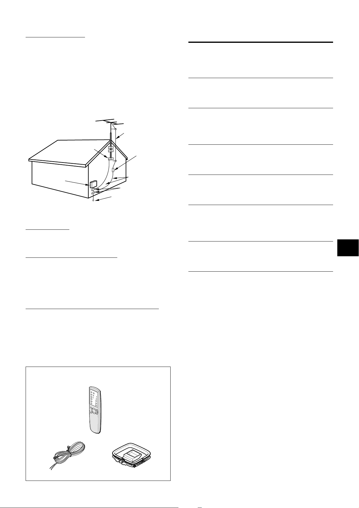
2 Outdoor antenna grounding — Be sure the antenna system
is properly grounded to provide protection against unexpected
voltage surges or static electricity build-up. Article 810 of the
National Electrical Code, ANSI/NFP A70, provides inf ormation
on proper grounding of the mast, supporting structure, and
the lead-in wire to the antenna discharge unit, as well as the
size of the grounding unit, connection to grounding terminals,
and requirements for grounding terminals themselves.
Antenna Grounding According to the National Electrical Code
ANTENNA LEAD IN WIRE
GROUND CLAMP
ANTENNA DISCHARGE
UNIT
(NEC SECTION 810-20)
TABLE OF CONTENTS
PRECAUTIONS...................................................................1
PREPARATIONS
CONNECTIONS .................................................................. 3
BEFORE OPERATION........................................................7
SOUND
CUSTOM AUDIO ADJUSTMENT .......................................8
ELECTRONIC GRAPHIC EQUALIZER..............................9
DSP SURROUND..............................................................10
BASIC OPERATIONS
SELECTION OF AUDIO/VIDEO SOURCE.......................11
RECORDING AN AUDIO SOURCE .................................12
ELECTRIC
SERVICE
EQUIPMENT
NEC-NATIONAL ELECTRICAL CODE
GROUNDING
CONDUCTORS
(NEC SECTION 810-21)
GROUND CLAMPS
POWER SERVICE GROUNDING
ELECTRODE SYSTEM
(NEC ART 250 PART H)
Maintenance
Clean the unit only as recommended in the Operating
Instructions.
Damage Requiring Service
Have the unit serviced by a qualified service technician if:
- The AC power cord or plug has been damaged
- Foreign objects or liquid have gotten inside the unit
- The unit has been exposed to rain or water
- The unit does not seem to operate normally
- The unit exhibits a marked change in performance
- The unit has been dropped, or the cabinet has been damaged
DO NOT ATTEMPT TO SERVICE THE UNIT YOURSELF.
RADIO RECEPTION
MANUAL TUNING .............................................................13
PRESETTING STATIONS .................................................14
DOLBY SURROUND
SELECTING DOLBY SURROUND................................... 15
ADJUSTING SPEAKER LEVEL BALANCE .................... 16
ADJUSTING DOLBY DIGITAL SURROUND SOUND .....18
TIMER
SETTING THE CLOCK......................................................19
SETTING THE SLEEP TIMER .......................................... 19
GENERAL
SPECIFICA TIONS ............................................................. 20
CARE AND MAINTENANCE ............................................ 21
TROUBLESHOOTING GUIDE.......................................... 21
PARTS INDEX ...................................................................21
EnEn
En
EnEn
EE
(Españo(Españo
E
(Españo
(Españo(Españo
EE
FF
(França (França
F
(França
(França (França
FF
Check your accessories
Remote control
FM antenna AM antenna
Operating Instructions, etc.
ENGLISH
2
PREPARATIONS
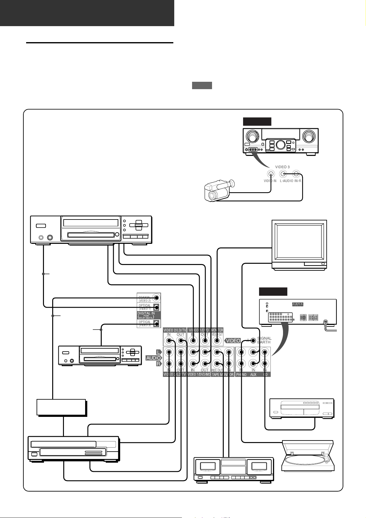
CONNECTIONS
Before connecting the AC cord
The rated voltage of your unit shown on the rear panel is 120 V
AC. Check that the rated voltage matches your local voltage.
IMPORTANT
Connect the speakers, antennas, and all other external
equipment first. Then connect the AC cord at the end.
*1Be sure to connect the VIDEO OUT terminal of a DVD player
directly to a TV set, not through this unit. Otherwise, the picture
noise may appear when playing copy protected DVDs.
*2Input sound through the DIGITAL IN terminals cannot be
recorded. When recording the sound from the DVD, CD, MD
or LD player , connect the analog A UDIO OUT terminals of the
player to the corresponding A UDIO IN terminals of the receiver.
*3When connecting a monaural video, use a stereo-mono
connecting cord (not supplied).
*4When connecting an LD player equipped with the AC-3 RF
OUT terminal, use an RF demodulator unit. Also connect the
analog AUDIO OUT terminals of the LD player to the receiver
to play all the sources. For further information, refer to the
instructions of the LD player.
DVD or Video 1* /MD player
3
CONNECTING EQUIPMENT
Jacks and plugs of the connecting cord are color-coded as
follows:
Red jacks and plugs : For the right channel of audio signals
White jacks and plugs: For the left channel of audio signals
Yellow jacks and plugs: For video signals
NOTE
Insert the plugs fully into the jacks. Loose connections may
produce a humming sound or other noise interference.
FRONT
Camcorder
to VIDEO OUT
to AUDIO OUT
TV
to OPTICAL
DIGITAL OUT
(DVD)
Optical
connecting
cord
Video 2* or
LD* /Cable TV
3
4
Coaxial connecting
cord
Optical
connecting
cord
DVD or MD,CD Player
to COAXIAL
DIGITAL OUT
RF demodulator*
to AUDIO OUT
to VIDEO OUT(Video 1)*
o
o
o
to OPTICAL
DIGITAL OUT
4
to AUDIO OUT
to AUDIO IN(Video 1/MD)
to VIDEO IN(Video 1)
o
1
o
2
*
2
*
o
o
to VIDEO OUT
o
o
to LINE IN
Tape deck
to VIDEO IN
to AUDIO OUTPUT
o
o
o
o
o
to LINE OUT
REAR
o
CD player
to OUTPUT
Turntable
3
ENGLISH
to AUDIO IN (Video 2)
to VIDEO IN (Video 2)
o
o
1 and 2 in the illustration correspond to the following details.
2
1
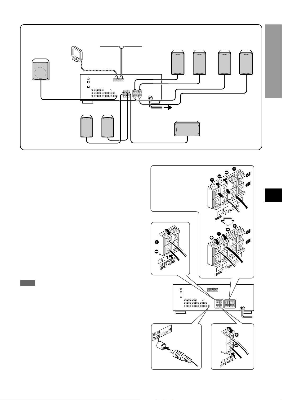
Sub woofer
AM antenna
2
FM antenna
1
Speaker system A
Right Left
1
Speaker system B
Right Left
PREP ARATIONS
Right Left
1
Surround speakers
CONNECTING SPEAKERS1
Speaker terminals
Connect front speakers (system A and/or B), a center speaker,
surround speakers and sub woofer to the corresponding speak er
terminals on the unit:
- the front speaker cords to the FRONT SPEAKERS terminals
- the center speaker cord to the CENTER SPEAKER terminals
- the surround speaker cords to the SURROUND SPEAKERS
terminals.
- for more powerful bass, the sub woof er (with a built-in amplifier)
cord to the SUB WOOFER 3 jack
When connecting the sub woofer, be sure to select the
“SUBW ON” (sub woofer on) mode (see page 5).
Speaker impedance
For all speakers, use speakers of 8 ohms or more.
1
Center speaker
Front speakers
Lift up the terminal flap,
insert the speaker cord lead
into the terminal slot, then
close the flap. Check that the
cord is connected securely.
Surround speakers
EnEn
En
EnEn
EE
(Españo(Españo
E
(Españo
(Españo(Españo
EE
FF
(França (França
F
(França
(França (França
FF
Connecting + to +, – to – terminals
T o get the proper sound eff ect, the speak er terminals on the unit
and the speaker should be connected with proper polarity; the +
terminal on the unit should be connected to the + terminal on
the speaker (and – to –).
NOTE
• Be sure to connect the speaker cords correctly as shown in
the illustration on the right column. Improper connections can
cause short circuits in the SPEAKER(S) terminals.
• Do not leave objects gener ating magnetism near the speakers.
Sub woofer
Center speaker
ENGLISH
4
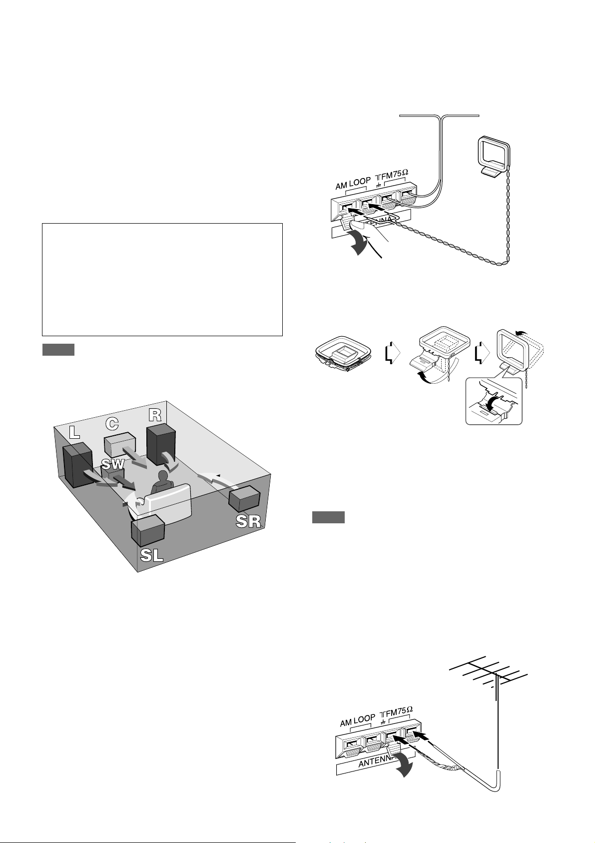
POSITIONING THE SPEAKERS
Position the speakers to mak e the most of DOLBY SURROUND
or DSP effect.
CONNECTING THE SUPPLIED ANTENNAS 2
Connect the FM antenna to the FM 75 Ω terminals and the AM
antenna to the AM LOOP terminals.
Front speakers (L/R)
Center speaker (C)
Position in the center of the two front speakers. In addition,
position on or below the TV set, if connecting a TV set to the
unit.
Surround speakers (SL/SR)
Place the surround speakers directly to the side of or slightly
behind the listening area. Align them horizontally, about 1 meter
(3.2 feet) above ear height.
Sub woofer (SW)
Place the sub woofer in any place between the tw o front speakers.
When connecting a sub woofer
Select “SUBW ON” mode.
1. Press the MANUAL SELECT b utton on the remote control
once so that “SUBW OFF” appears on the display.
2. Within 4 seconds, press the TUNING M button or turn
the MULTI JOG to the left to display “SUBW ON.”
If a sub woofer is not connected, be sure to select “SUBW
OFF.”
Display “SUBW ON” in step 1 and press the TUNING N
button or turn the MULTI JOG to the right in step 2.
NOTE
Sound from the surround speakers or center speaker depends
on the setting of DOLBY SURROUND or DSP surround.
FM antenna
AM antenna
To stand the AM loop antenna on a surface
Fix the claw to the slot as shown in the illustration.
To position the antennas
FM feeder antenna:
Extend this antenna horizontally in a T shape and fix its ends to
the wall.
AM loop antenna:
Position for the best reception.
NOTE
• Do not bring the FM antenna near metal objects or curtain rails.
• Do not bring the AM antenna near other external equipment,
the unit itself, the AC power cord or speaker cords, as noise
will be picked up.
• Do not unwind the AM loop antenna wire.
CONNECTING AN OUTDOOR ANTENNA
For better FM reception, use of an outdoor antenna is
recommended. Connect the outdoor antenna to the FM 75 Ω
terminals.
5
ENGLISH
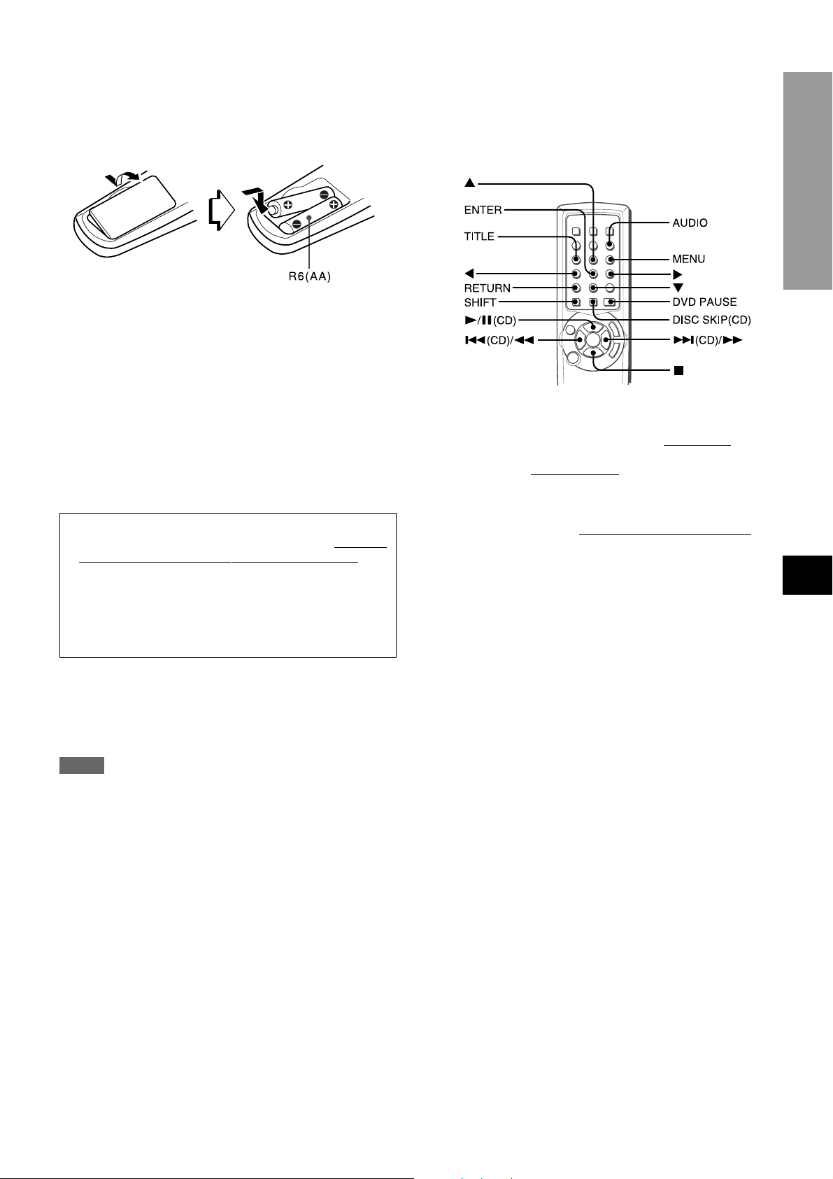
ABOUT THE REMOTE CONTROL
Inserting batteries
Detach the battery cover on the rear of the remote control and
insert two R6 (size AA) batteries.
When to replace the batteries
The maximum operational distance between the remote control
and the sensor on the unit should be approximately 5 meters
(16 feet). When this distance decreases, replace the batteries
with new ones.
Using the remote control
The instructions in this manual refer mainly to the buttons on the
main unit.
Some buttons have two functions.
• To use the function indicated on the button, or on the plate in
black, simply press the button.
• To use the function indicated on the plate in green, press the
button while pressing the SHIFT button.
Important
• The ENTER button on the remote control does not
substitute for the ENTER button on the main unit. This
button is for operating the DVD player only (see right
column.)
• In principal, the TUNING UP and DOWN buttons on the
remote control substitute for N and M buttons on
the main unit. Press the button while pressing the SHIFT
button.
To select the function (audio source) with the remote
control
Press the FUNCTION button repeatedly. The function changes
cyclically.
Operating AIWA CD or DVD players with the remote
control
You can control the basic functions of AIWA CD or DVD players
with the remote control. In principle, the buttons described belo w
have the same function as those on the DVD or CD players.
For more details, refer to the operating instructions of the pla yer .
Operating DVD and CD players
Press the following button.
l/a - Starts playback. The b utton pauses
f,g - Searches a track. Hold the button down.
r,t - Skips
s - Stops playback.
a track of the CD . Press the button repeatedly.
CD playback as well.
Operating DVD players
Press the following button while pressing the SHIFT button.
i,k,j,l (up, down, left or right) button - Moves the cursor to
select a program etc.
AUDIO button - Changes an audio track (language etc.)
ENTER button - Enters the selected program etc.
TITLE or MENU button - Enters the title or menu screen.
RETURN button - Returns to the previous mode etc.
DVD PAUSE - Pauses the playback of a DVD.
Operating CD players
Press the following button.
DISC SKIP (CD) - Skips a disc in the CD changer.
PREPARATIONS
EnEn
En
EnEn
EE
(Españo(Españo
E
(Españo
(Españo(Españo
EE
FF
(França (França
F
(França
(França (França
FF
NOTE
• If the unit is not going to be used for an extended period of
time, remove the batteries to prevent possible electrolyte
leakage.
• The remote control may not operate correctly when:
- The line of sight between the remote control and the remote
sensor in the display window is exposed to intense light, such
as direct sunlight.
- Other remote controls are used nearby (those of a television,
etc.)
ENGLISH
6
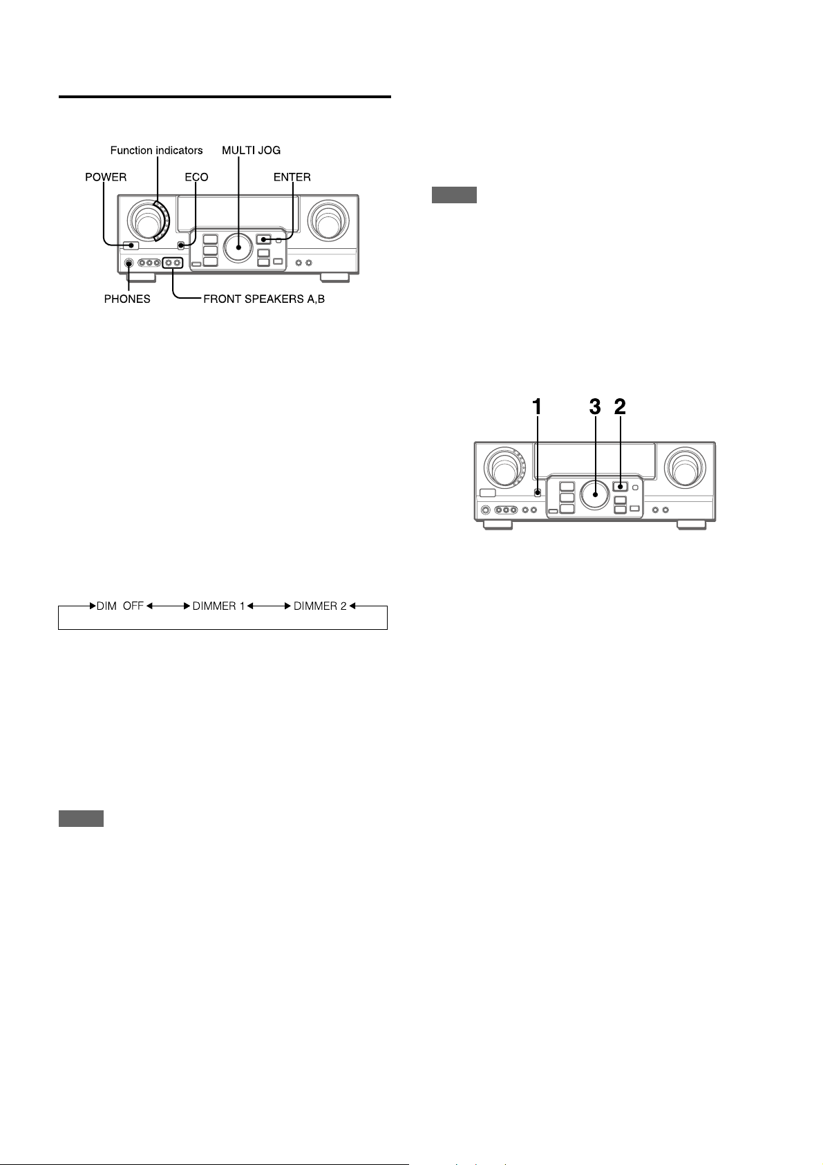
BEFORE OPERATION
To turn the unit on
To select the front speaker system
To use speaker system A: Set the FR ONT SPEAKERS A button
to HON.
To use speaker system B: Set the FR ONT SPEAKERS B button
to HON.
To use both speaker systems: Set both the buttons to HON.
Set the button(s) to hOFF to turn off the speaker system(s).
NOTE
As the front speaker systems A and B are connected in series:
- The sound will decrease slightly when using both speaker
systems
- No sound can be heard if the FRONT SPEAKERS A and B
buttons are set to HON when only one speaker system is
connected
To turn the unit off, press the POWER button.
Press the POWER b utton.
Operation is possible after four seconds . The VOL (v olume) le vel
or function name is displayed one after the other f or the first f our
seconds.
The selected function indicator lights up in red.
To change the brightness level of the display
1 Press the ECO button repeatedly until “DIM MODE” is
displayed.
2 Within 4 seconds, press the ENTER button.
3 Within 4 seconds, turn the MULTI JOG to select the dimmer
mode as below.
The mode will be automatically set after 4 seconds. It will
also be set if the ENTER button is pressed within 4 seconds
after step 3.
-
DIM-OFF: The normal display.
DIMMER 1: The illumination of the display is dimmer than
usual.
DIMMER 2: The illumination of the display is dimmer than
DIMMER 1. The function indicator turns off.
Using the headphones
Connect headphones to the PHONES jack with a standard stereo
plug (ø6.3 mm, 1/4 inch). Be sure to set the FR ONT SPEAKERS
A and B buttons to hOFF. Otherwise sound is output from the
speakers.
POWER ECONOMIZING (ECO) MODE
Setting this unit to the ECO mode reduces power consumption
as below.
Initial setting of the ECO mode is ON.
• When the current time is set, the clock display disappears
immediately.
• While the power is off, all the display lights turn off, and only
the indicator on the left side of the display window lights in red.
To cancel the ECO mode
1 Press the ECO button to display ECO MODE while the unit is
turned on.
2 Within 4 seconds, press the ENTER button.
3 Within 4 seconds, turn the MULTI JOG to select ECO OFF.
The mode will be automatically set after 4 seconds. It will
also be set if the ENTER button is pressed within 4 seconds
after step 3.
NOTE
When the headphones are plugged in:
- The Dolby Pro Logic or DSP system is automatically canceled
- The Dolby Digital Surround mode is changed to the
“2chSTEREO (2CH DOWNMIX)” mode
7
ENGLISH
SOUND
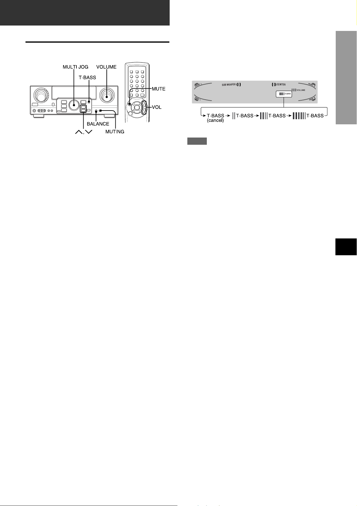
CUSTOM AUDIO ADJUSTMENT
VOLUME CONTROL
Turn the VOLUME control on the unit, or press the VOL buttons
on the remote control.
The volume lev el is shown on the displa y for f our seconds. It can
be adjusted between 0 and MAX (31). It flashes when set over
the level of 27.
The volume level remains memorized even after the power is
turned off. However, if the power is turned off when the volume
is set to 17 or more, it is automatically set to 16 the next time the
power is turned on.
SUPER T -BASS SYSTEM
The T-BASS system enhances the realism of low-frequency
sound.
Press the T-BASS button.
Each time it is pressed, the level changes. Select one of the
three levels, or the off position to suit your preference.
SOUND
PREPARATIONS
NOTE
Low-frequency sound may be distorted when the T-BASS system
is used for a disc or tape in which low-frequency sound is
originally emphasized. In this case, cancel the T-BASS system.
SOUND ADJUSTMENT DURING RECORDING
The output volume and tone of the speakers or headphones may
be freely varied without affecting the level of the recording.
To adjust the left/right balance of the front speakers
Press the BALANCE button to display “L/R 0dB”. Then press
the N or M button repeatedly or turn the MULTI JOG within
four seconds.
Note that the front speaker balance for the DOLBY SURR OUND
is also changed.
To mute the sound temporarily
Press the MUTING (MUTE) button (–20 dB).
“MUTE ON” appears on the display f or four seconds. While muting
the sound, the selected function indicator flashes. Press the
MUTING button again to restore the sound.
EnEn
En
EnEn
EE
(Españo(Españo
E
(Españo
(Españo(Españo
EE
FF
(França (França
F
(França
(França (França
FF
ENGLISH
8
ELECTRONIC GRAPHIC
EQUALIZER
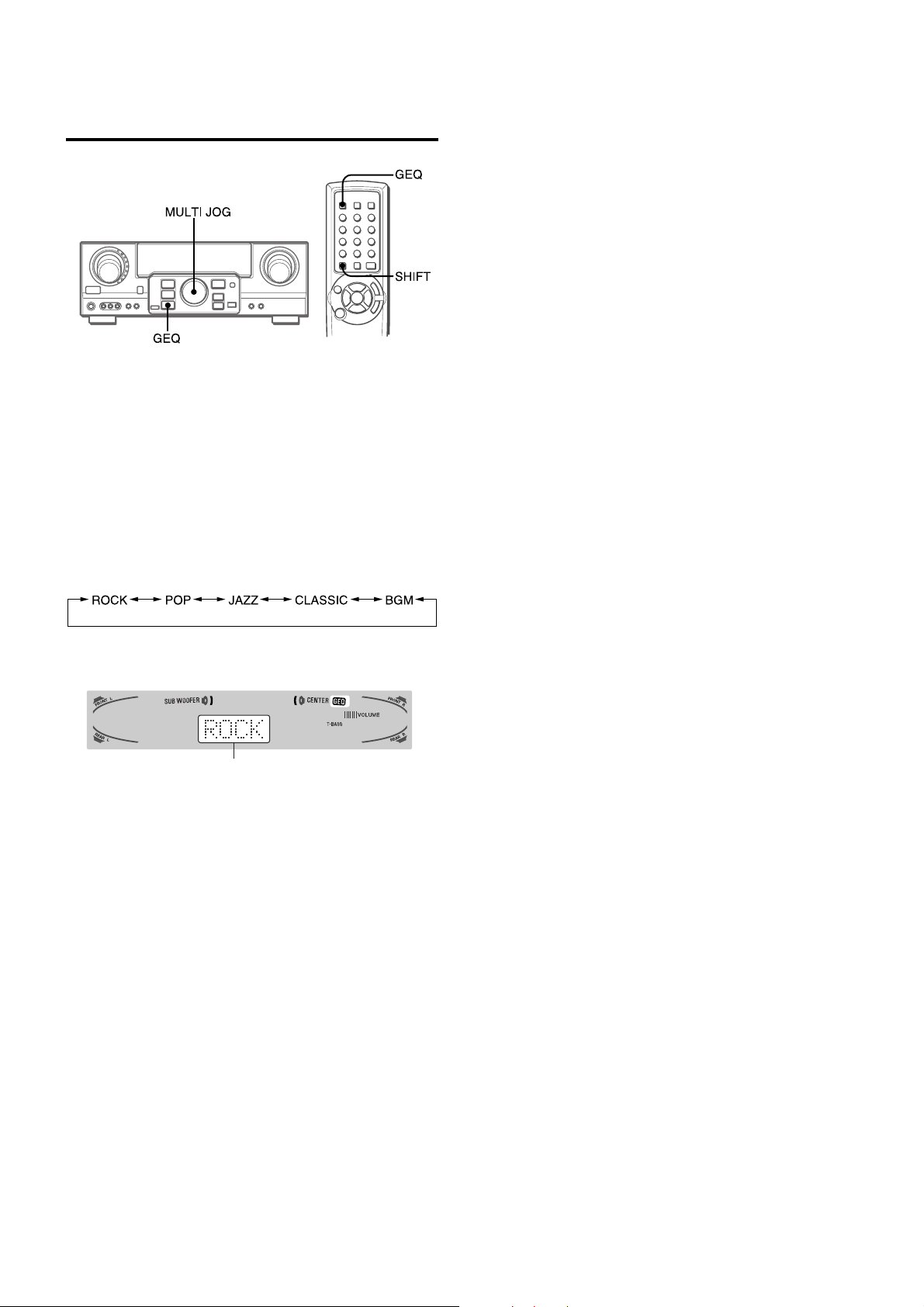
This unit provides the following fiv e different equalization modes.
ROCK: Powerful sound emphasizing treble and bass
POP: More presence in the vocals and midrange
JAZZ: Accented lower frequencies for jazz-type music
CLASSIC: Enriched sound with heavy bass and fine treble
BGM: Calm tone with suppressed bass and treble
Press the GEQ (Graphic Equalizer) button, and turn the
MULTI JOG until the desired equalization mode is
displayed.
The GEQ modes are displayed cyclically as follows.
To cancel the selected mode
Press the GEQ button to display the GEQ mode name, and press
the button again within 4 seconds. “GEQ OFF” appears on the
display.
To select with the remote control
Press the GEQ button repeatedly while pressing the SHIFT
button until the desired equalization mode is displayed.
Five preset modes and “GEQ OFF” can be selected.
The selected mode name is displayed f or f our seconds , and the
GEQ indicator lights up.
Selected mode
9
ENGLISH
DSP SURROUND
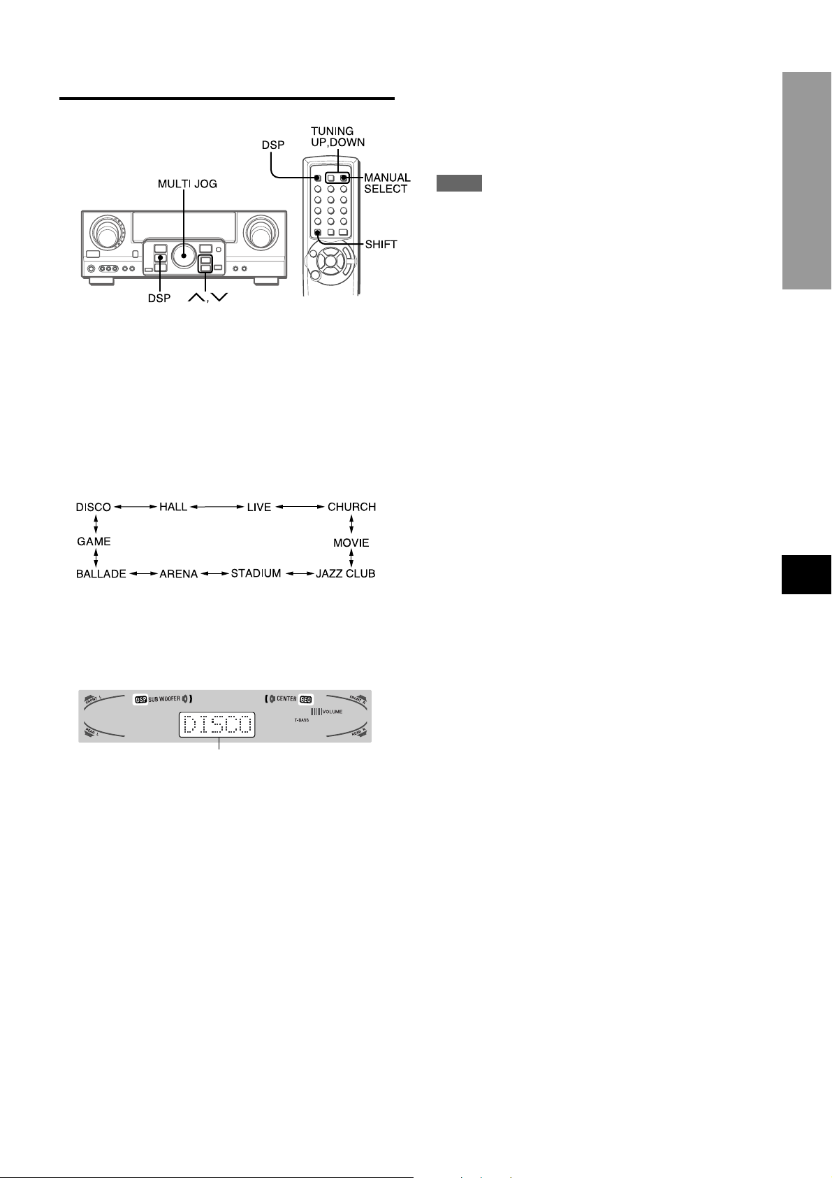
The DSP (Digital Signal Processor) surround circuits can recreate
the effect of sounds reflected from walls or ceilings, to obtain the
sound presence of real environments. The unit provides 10 DSP
preset modes. Some of them are accompanied with the matching
GEQ preset mode, and you can also select or turn off the GEQ
to suit your preference.
Press the DSP button, and turn the MULTI JOG until
the desired DSP mode is displayed.
To adjust the volume and balance of the surround
speakers
Press the MANUAL SELECT button on the remote control three
times to display “SUR 0dB” while the DSP system is turned on.
Then press the N or M button repeatedly or turn the MULTI
JOG within four seconds.
NOTE
The DSP surround system is automatically canceled and cannot
be turned on when headphones are plugged in.
SOUND
The selected mode name is displayed f or four seconds, and the
DSP indicator lights up. When the selected DSP mode is
accompanied with the matching GEQ mode, the GEQ indicator
lights up as well.
Selected mode
When the music source is monaural
The DSP system may not work effectively.
To cancel the selected mode
Press the DSP button to display the DSP mode name, and press
the button again within 4 seconds. “DSP OFF” appears on the
display. Ev en if canceling the selected DSP mode , the matching
or selected GEQ mode still remains.
To select with the remote control
1 Press the DSP button.
2 Within 4 seconds, press the TUNING UP or DOWN button
repeatedly while pressing the SHIFT button until the desired
DSP mode is displayed.
Ten preset modes can be selected.
To change the mode rapidly, hold down the TUNING UP or
DOWN button while pressing the SHIFT button.
EnEn
En
EnEn
EE
(Españo(Españo
E
(Españo
(Españo(Españo
EE
FF
(França (França
F
(França
(França (França
FF
ENGLISH
10
BASIC OPERATIONS
SELECTION OF AUDIO/VIDEO
SOURCE
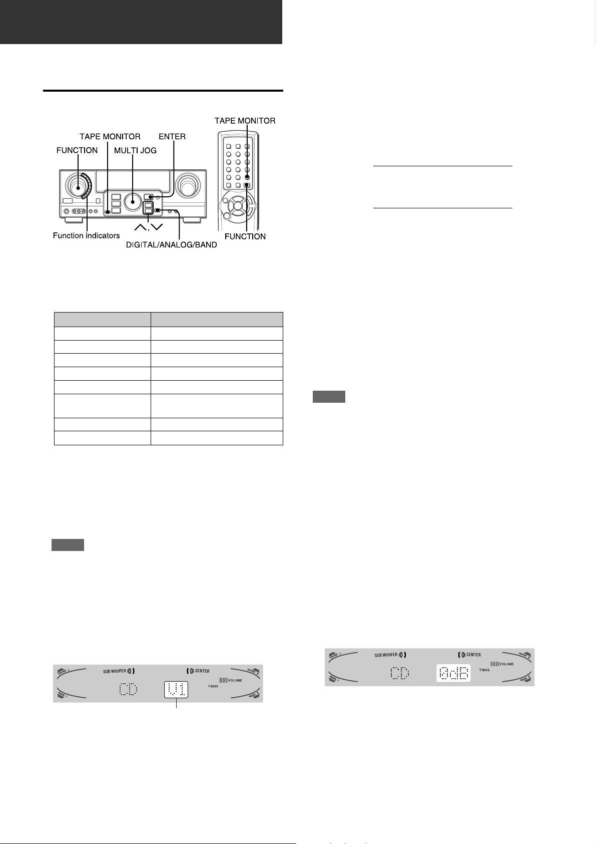
1 Select the program source.
Turn the FUNCTION selector or press the TAPE MONITOR
button. The selected function indicator lights in red.
To listen to or watch The indicator in red
Tape TAPE MONITOR
Radio TUNER
Record PHONO
Compact disc CD
Television, etc. AUX
Video VIDEO 1/DVD/MD,
VIDEO 2/LD/TV, VIDEO 3
LD or Cable TV VIDEO 2/LD/TV
MD or DVD VIDEO 1/DVD/MD
The function to be selected (except PHONO) depends on the
equipment connected to the input terminals on the rear panel
of the unit.
To select with the remote control
Press the TAPE MONITOR button or the FUNCTION button
repeatedly.
NOTE
When using a turntable with a built-in equalizer amplifier , set
the switch of the equalizer amplifier to off. See the instructions
of the turntable for further information.
T o select the video sour ce
1 Tur n the FUNCTION to select PHONO, CD or AUX.
2 Press the ENTER button to display VIDEO 1.
3 Tur n the MULTI JOG to select VIDEO 2 or VIDEO 3.
To change a displayed name for the VIDEO 1
and VIDEO 2
When the VIDEO 1 function is selected, VIDEO 1 is displayed
initially. It can be changed to DVD or MD.
Press the DIGITAL/ANALOG/BAND button while pressing the
ENTER button,
The displayed name for the VIDEO 2 function can be changed
to VIDEO 2, LD or TV; while the VIDEO 2 function is selected,
press the DIGITAL/ANALOG/BAND button while pressing the
ENTER button,
then release the ENTER button first.
then release the ENTER button first.
To select the “ANALOG” or “DIGITAL” (Dolby
Digital Surround) mode of the VIDEO 1, VIDEO
2 or VIDEO 3 function
Press the DIGITAL/ANALOG/BAND button when the VIDEO 1,
VIDEO 2 or VIDEO 3 is selected. The selected mode “ANALOG”
or “DIGITAL” appears on the display.
In the DIGITAL mode: Equipment connected to the OPTICAL
DIGITAL IN terminal is selected as a source for the VIDEO 1 or
VIDEO 3 function, and equipment connected to the COAXIAL
DIGITAL IN terminal for the VIDEO 2 function. The DIGITAL
indicator lights in red.
In the ANALOG mode: Equipment connected to the VIDEO 1/
DVD/MD IN or VIDEO 3 terminals is selected as a source for the
VIDEO 1 or VIDEO 3 function, and equipment connected to the
VIDEO 2/LD/TV terminals for the VIDEO 2 function.
NOTE
The “DIGITAL” mode changes to the “ANALOG,” when pressing
the TAPE MONITOR button.
When the “OVER LEVEL” indicator lights up
The unit is equipped with the OVER LEVEL indicator . When input
analog signals from the connected equipment are too high to
accept, the indicator lights on the right side of the display . In this
case, adjust the input level as mentioned below so that the
indicator disappears.
To adjust the sound level of the connected source
The input sensitivity level of each function can be adjusted
(except the TUNER, VIDEO 1 (DIGITAL), VIDEO 2 (DIGITAL)
and VIDEO 3 (DIGITAL) functions).
When the sound level of the connected source is higher or low er
than that of the TUNER, adjust it as follows.
2 Start the selected program source.
3 Adjust the sound.
About the video source to the monitor or TV
Selected video source
V1: VIDEO 1, V2: VIDEO 2, V3: VIDEO 3
The selected video source is indicated on the display and the
video signal through the MONITOR VIDEO OUT jack is output
on the TV.
11
ENGLISH
1 Select the function to be adjusted.
Turn the FUNCTION or press the TAPE MONITOR button
and play the source.
2 Press the N or M button repeatedly.
Adjust the level so that the “O VER LEVEL” indicator does not
light on the display.
• The level can be adjusted between -6dB (MIN) and +8dB
(MAX) in 2dB steps. Adjust the level so that the sound is
output at the same level as the TUNER.
• The input sensitivity level of the TAPE MONITOR can be
adjusted to 0dB or -6dB.
TO PLAY A DVD OR LD RECORDED IN
DOLBY DIGITAL SURROUND
This receiver is equipped with the Dolby Digital decoder and
has the DIGITAL IN (both OPTICAL and COAXIAL) terminals.
When a DVD or LD pla yer is connected to the DIGITAL IN terminal
of the receiver, you can enjoy theater-quality audio right in your
home when playing discs recorded in Dolby Digital Surround.
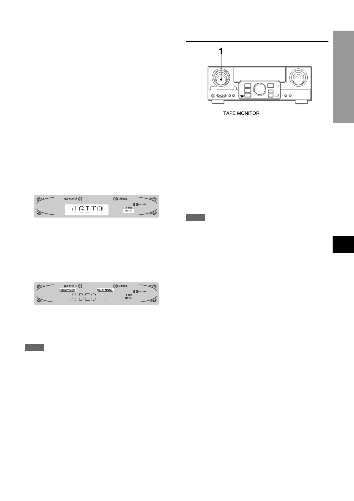
Before operation
• Check that the TAPE MONITOR is not selected. If the TAPE
MONITOR is selected, press the TAPE MONITOR button so
that “TAPE OFF” appears on the display.
• When connecting an LD player equipped with the AC-3 RF
OUT terminal, use an RF demodulator unit. Also connect the
analog AUDIO OUT terminals of the LD player to the receiv er
to play all the sources. For further information, refer to the
instructions of the LD player.
RECORDING AN AUDIO SOURCE
BASIC OPERATIONS
1 Select the program source to be recorded.
Turn the FUNCTION.
2 Set the tape deck or MD recorder to the recording
mode.
1 T urn the FUNCTION to select the VIDEO 1 (VIDEO
2 or VIDEO 3) and press the DIGITAL/ANALOG/
BAND button repeatedly until “DIGITAL” is
displayed.
The DVD (LD) pla y er connected to the OPTICAL (CO AXIAL)
DIGITAL IN terminal is selected as a source.
2 Start playing the DVD (LD) recorded in Dolby
Digital Surround.
The “DOLBY DIGITAL” indicator will light on the displa y when
the bit stream of the Dolby Digital Surround comes in the
unit.
To select the Dolby Digital Surround mode according to your
speakers, see “SELECTING DOLBY SURROUND” on page
15.
3 Start the selected program source.
To monitor recorded sound during recording (when the
connected tape deck is a three-head system)
Press the TAPE MONITOR button. “TAPE ON” appears on the
display for four seconds, and then the source name selected in
step 1 comes back on. To cancel the tape monitor, press it again
so that “TAPE OFF” appears.
NOTE
• Any sound control system has no effect on recording (see
page 8).
• Input sound through the DIGITAL IN ter minals cannot be
recorded. When recording the sound from the DVD, CD, MD
or LD player, connect the analog AUDIO OUT terminals of
the player to the corresponding AUDIO IN terminals of the
receiver.
The sound will be recorded in 2 ch stereo.
• When recording audio sources by the MD recorder connected
to the VIDEO 1/D VD/MD A UDIO OUT terminals, the selected
video source (see page 11) should be V2 or V3. Recording
cannot be done while the V1 (VIDEO 1) is selected and
displayed on the window.
• Input sound from the tape deck connected to the TAPE
MONITOR IN terminals cannot be recorded.
EnEn
En
EnEn
EE
(Españo(Españo
E
(Españo
(Españo(Españo
EE
FF
(França (França
F
(França
(França (França
FF
NOTE
• While the TAPE MONITOR is selected and the TAPE MONITOR
indicator turns red, “DIGITAL” cannot be selected.
• When headphones are plugged in, the Dolby Digital Surround
mode is automatically changed to “2chSTEREO” and the “2CH
DOWNMIX” indicator lights on the display.
Even if the DOLBY SURROUND button is pressed while the
headphones are plugged in, the mode cannot be changed.
• This unit supports input signals of the Dolby Digital Surround
bit stream and linear PCM whose sampling frequency is 32
kHz, 44.1 kHz and 48 kHz. The unit cannot pla y the DVDs whose
sampling frequency is 96 kHz.
• When connecting some DVD players to the receiver through
the DIGITAL IN terminals, noise may be heard in the DVD
operation: e.g. searching a disc, skipping a chapter.
ENGLISH
12
RADIO RECEPTION
MANUAL TUNING
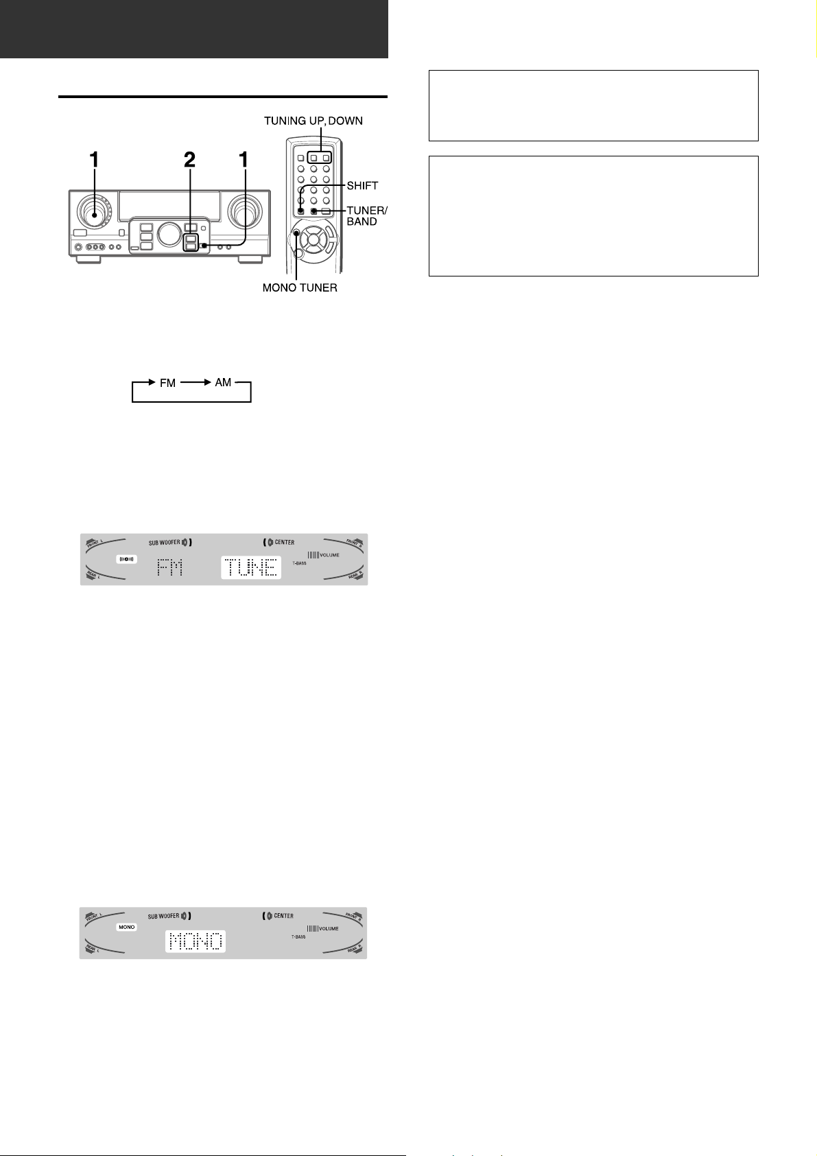
1 T urn the FUNCTION to select the TUNER function,
and press the DIGITAL/ANALOG/BAND button
repeatedly to select the desired band.
The display changes to frequency indications after indicating
band and video source (V1, V2 or V3) for two seconds.
2 Press the N or M button to select a station.
Each time the button is pressed, the frequency changes.
When a station is received, “TUNE” is displayed for two
seconds. During FM stereo reception, 1 is displayed.
When the reception contains noise interference
Move the unit awa y from other electrical appliances, especially
digital audio devices, or turn off the appliances that generate
noise signals.
To change the AM tuning interval
The default setting of the AM tuning interval is 10 kHz/step. If
you use this unit in an area where the frequency allocation
system is 9 kHz/step, change the tuning interval.
Hold down the DIGIT AL/ANALOG/BAND b utton and press the
POWER button.
To reset the interval, repeat this procedure.
When operating with the remote control
Press the TUNER/BAND button while pressing the SHIFT b utton
in step 1, and the TUNING DOWN or UP button while pressing
the SHIFT button in step 2.
To search for a station quickly (Auto Search)
Keep the N or M button pressed until the tuner star ts
searching for a station. After tuning in to a station, the search
stops.
To stop the Auto Search manually, press the N or M button.
When operating with the remote control, keep the TUNING UP
or DOWN button pressed while pressing the SHIFT button.
• The Auto Search may not stop at stations with very weak
signals.
When an FM stereo broadcast contains noise
Press the MONO TUNER button while pressing the SHIFT b utton
on the remote control so that “MONO” appears on the display.
Noise is reduced, although reception is monaural.
To restore stereo reception, repeat the above so that “STEREO”
appears.
13
ENGLISH
PRESETTING STATIONS
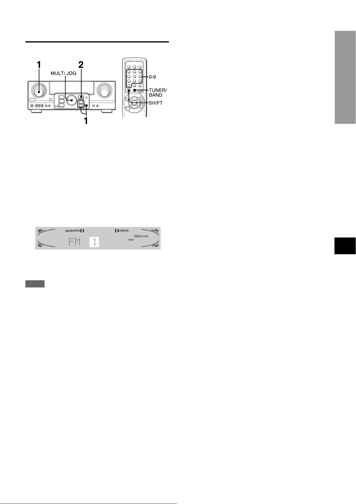
PRESET NUMBER TUNING
1 T urn the FUNCTION to select the TUNER function,
and press the DIGITAL/ANALOG/BAND button
repeatedly to select a band.
2 Turn the MULTI JOG to select a preset number.
When operating with the remote control
Press the TUNER/BAND button while pressing the SHIFT b utton
to select a band, then press the numbered buttons to select a
preset number.
Example:
To select preset number 25, press 2 and 5.
To select preset number 7 press 0 and 7.
RADIO RECEPTION
The unit can store a total of 32 preset stations. When a station is
stored, a preset number is assigned to the station. Use the preset
number to tune in to a preset station directly.
1 T urn the FUNCTION to select the TUNER function,
and press the DIGITAL/ANALOG/BAND button
repeatedly to select the desired band. Then press
the N or M button to select a station.
2 Press the ENTER button to store the station.
A preset number assigned to the station, beginning from 1 in
consecutive order for each band, appears in the display for
two seconds.
3 Repeat steps 1 and 2.
No more stations will be stored and “FULL” appears if a total
of 32 stations have already been stored for all the bands.
NOTE
When the AM tuning interval is changed, all preset stations are
cleared. The preset stations have to be set again.
To clear a preset station
Select the preset number of the station to be cleared. Then, press
the ENTER button, and press it again within four seconds.
The preset numbers of all other stations in the band with higher
numbers are decreased by one.
EnEn
En
EnEn
EE
(Españo(Españo
E
(Españo
(Españo(Españo
EE
FF
(França (França
F
(França
(França (França
FF
ENGLISH
14
DOLBY SURROUND
This unit is equipped with not only the Dolby Pro Logic decoder
but also the Dolby Digital decoder.
The unit and the center and surround speakers (standard) assure
full-scale home theater sound. When pla ying back discs or video
software that have been recorded in Dolby Pro Logic or Dolby
Digital Surround, astonishingly realistic sound surrounds the
listener to create a new level of audio/visual entertainment.
Independent control of the five channels allows the listener to
enjoy the same type of sound reproduction experienced in movie
theaters. Voices are reproduced in the front and center sound
field, while ambient sounds like cars and crowds are reproduced
on all sides of the listener for an incredibly lifelike audio/video
experience. Please read the following carefully to “tune” the
system’s output to match the characteristics of your listening
space.
Check the following:
• Before enjoying the DOLBY SURROUND sound, adjust the
speaker sound levels to the proper balance (see page 16).
• Make sure the speakers are properly connected and positioned
(see pages 4 and 5).
• Make sure the TV set and video unit are properly connected
(see page 3).
• Make sure the disc and video tape, etc., support Dolby Pro
Logic or Dolby Digital Surround.
SELECTING DOLBY SURROUND
TO SELECT A DOLBY SURROUND MODE
Preparations
• When selecting a Dolby Digital Surround mode, select the
VIDEO 1 (DIGIT AL), VIDEO 2 (DIGITAL) or VIDEO 3 (DIGIT AL)
function (see page 12) and play a disc recorded in Dolby
Digital Surround before selecting the mode.
• When selecting a Dolby Pro Logic mode, select the function
except VIDEO 1 (DIGITAL), VIDEO 2 (DIGITAL) and VIDEO 3
(DIGITAL).
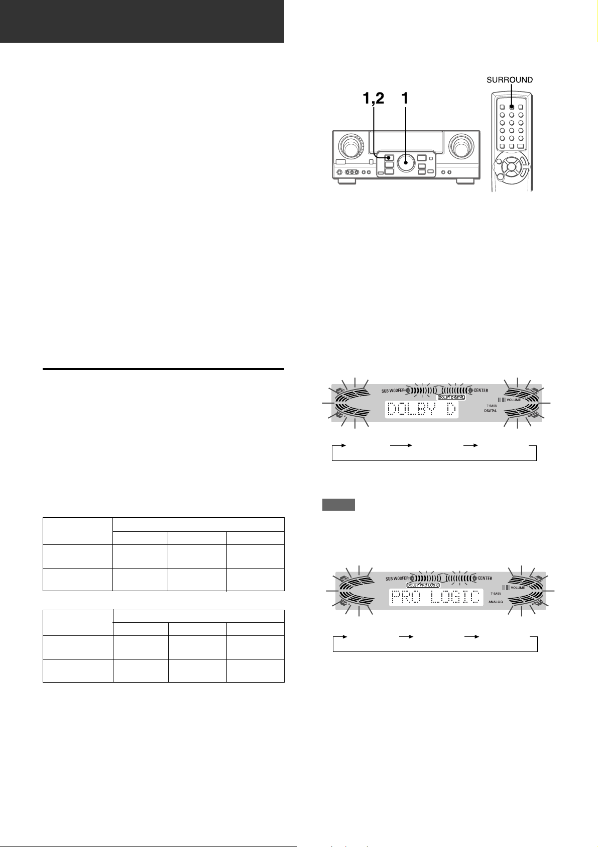
1 Press the DOLBY SURROUND button and turn
the MULTI JOG to select the appropriate mode.
The selected mode name appears on the display.
[Dolby Digital Surround]
The optimal Dolby Digital Surround and Dolby Pro Logic modes
and settings depend on the type and placement of the speakers.
It is recommended that the optional Aiwa speakers should be
used for all channels, for example, the SX-AVR2900 speaker
system.
Check the current type and placement of your speakers and
select the recommended mode accordingly.
The recommended mode
[Dolby Digital Surround]
Center speaker
Surround speaker
(Rear speaker)
No surround
speaker
Larger-size
DOLBY
D-WIDE
3 STEREO-
WIDE
Smaller-size
DOLBY
D-NORMAL
3 STEREO-
NORMAL
No speaker
PHANTOM
2chSTEREO
[Dolby Pro Logic]
Center speaker
Surround speaker
(Rear speaker)
No surround
speaker
Larger-size
PRO LOGIC-
WIDE
3 STEREO-
WIDE
Smaller-size
PRO LOGIC-
NORMAL
3 STEREO-
NORMAL
No speaker
PHANTOM
–
DOLBY D PHANTOM 3 STEREO
To select the 2chSTEREO mode, press the DOLBY
SURROUND button repeatedly until “2chSTEREO” appears.
NOTE
Select the Dolby Digital Surround mode while playing a source
recorded in Dolby Digital Surround.
[Dolby Pro Logic]
PRO LOGIC PHANTOM 3 STEREO
PHANTOM mode: Select this mode when the center speaker is
not connected. All center channel signals are redistributed to
the left and right channel speakers.
3 STEREO mode: Select this mode when the surround speakers
are not connected.
15
ENGLISH
2 Press the DOLBY SURROUND button again and
hold it down until the center speaker mode to be
selected appears. (Except the 2chSTEREO and
PHANTOM modes.)
“NORMAL” and “WIDE” appear one after the other.
When operating with the remote control
Press the SURROUND button repeatedly to select the mode,
and hold it down to select the center speaker mode.
ADJUSTING SPEAKER LEVEL
BALANCE
NOTE
• Depending on the sound source or listening condition, surround
effect may not be obtained even when the Dolby Digital
Surround or Dolby Pro Logic is selected.
• The full Dolby Digital Surround or Dolby Pro Logic eff ect cannot
be obtained when using software not recorded in the Dolby
Digital Surround or Dolby Pro Logic system. In this case, use
the DSP surround system instead (see page 10).
• When headphones are plugged in:
- The Dolby Pro Logic system is automatically canceled.
- The Dolby Digital Surround mode is automatically changed
to “2chSTEREO.”
• While headphones are plugged in:
- The Dolby Pro Logic cannot be turned on.
- The Dolby Digital Surround mode cannot be changed.
The unit is equipped with a built-in test signal generator called a
noise sequencer for easy balance adjustment of all five channels.
The sequencer outputs a noise signal that “trav els” from channel
to channel, enabling the simple adjustment of sound level to
achieve the same apparent loudness, at your listening position,
from each channel.
1 Select the Dolby Digital Surround (except
“2chSTEREO”) or Dolby Pro Logic mode
according to the current type and placement of
your speakers.
(See page 15.)
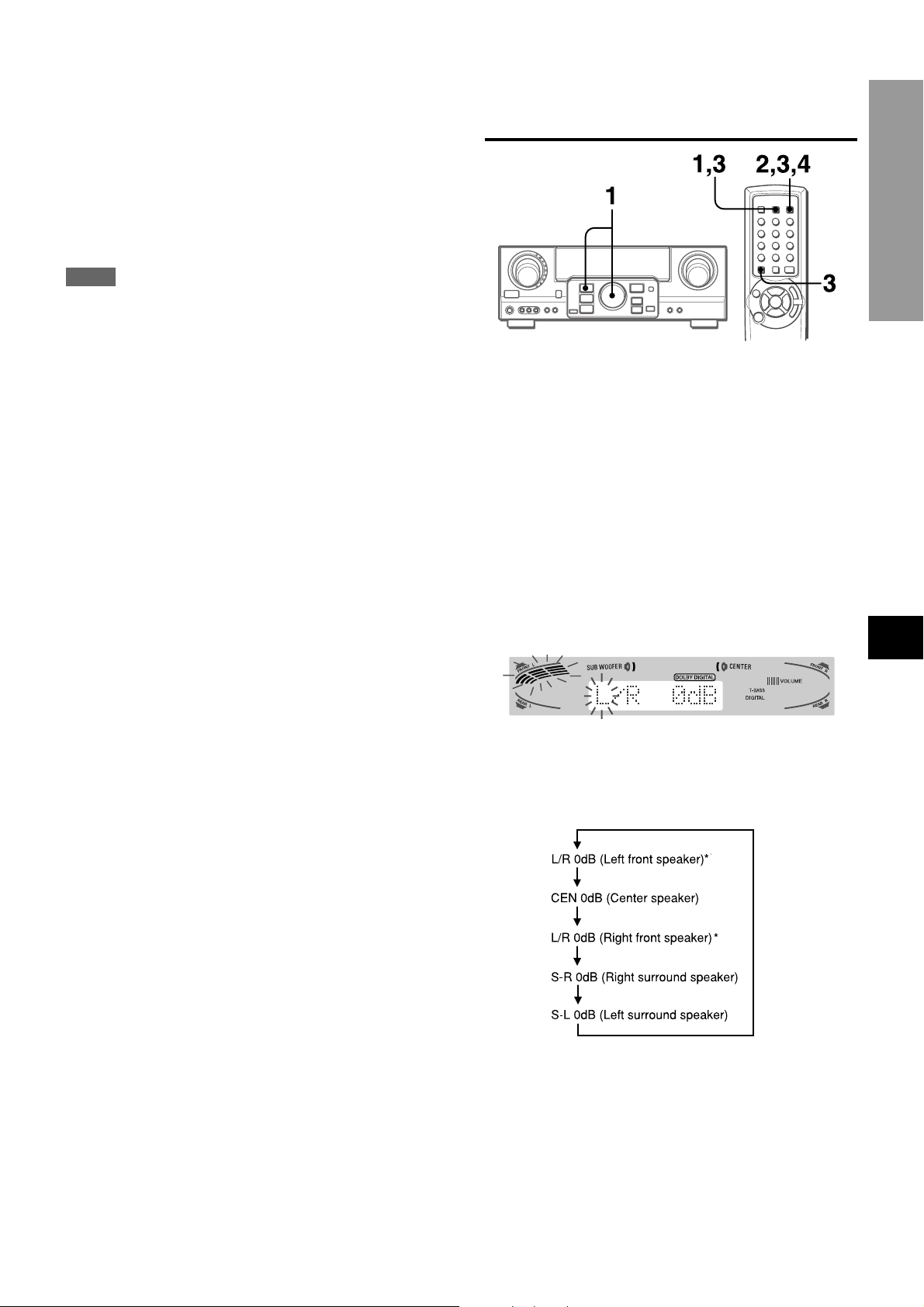
2 Press the MANUAL SELECT b utton on the remote
control and hold it down for about two seconds
until “L” of “L/R 0dB” starts to flash.
DOLBY SURROUND
EnEn
En
EnEn
EE
(Españo(Españo
E
(Españo
(Españo(Españo
EE
A noise signal is sent to each channel in turn as follows:
DOLBY D (PRO LOGIC) NORMAL or WIDE mode
To be continued
FF
(França (França
F
(França
(França (França
FF
ENGLISH
16
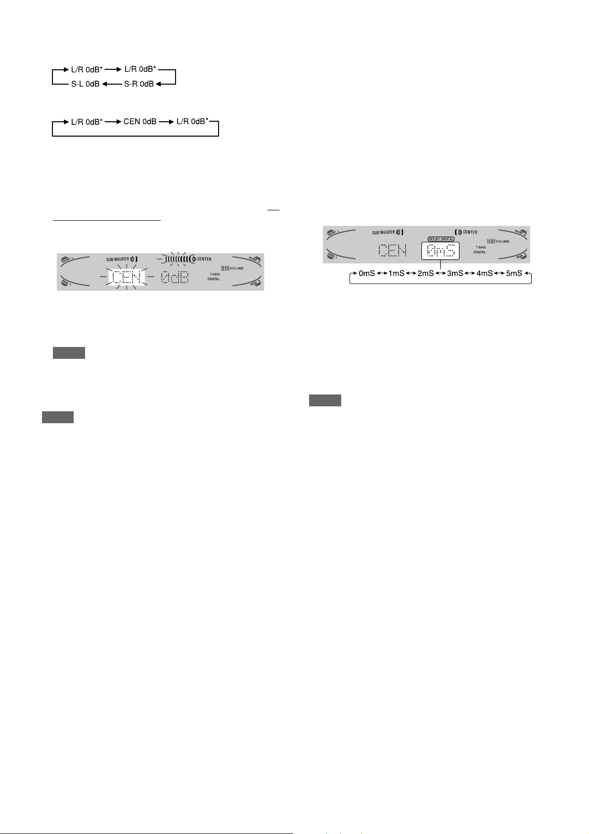
PHANTOM mode
3 STEREO NORMAL or WIDE mode
To change the delay time of the surround speakers or
center speaker when using the Dolby Digital Surround
or Dolby Pro Logic mode
While the Dolby Digital Surround (except “2chSTEREO”) or Dolby
Pro Logic is activated, press the MANUAL SELECT button on
the remote control repeatedly so that “CEN 0mS” or “SUR 5mS”
(SUR 20mS) is displayed. Then, within 4 seconds, press the
N or M b utton or turn the MUL TI JOG. The delay time changes
as shown below.
* “L” or “R” flashes to indicate one of the front speakers from
which the noise signal is output.
3 Adjust the sound level of the center and surround
speakers.
While “CEN,” “S-L” or “S-R” flashes in the display, press the
TUNING UP or DOWN button while pressing the SHIFT button
on the remote control so that the sound level of the center or
surround speakers matches that of the front speakers.
The balance of the front speakers can be adjusted as well
while “L/R” is displayed.
NOTE
The N or M button on the main unit cannot be used.
4 Press the MANUAL SELECT b utton again to stop
the noise signal.
NOTE
When adjusting the speaker level balance of the Dolby Digital
Surround, that of the Dolby Pro Logic is also changed and vice
versa.
About the channels
The left and right speakers create the stereo effect.
The center speaker helps precise sound positioning over a
broad sound field.
The rear-mounted surround speakers enhance the “depth” of
the sound field.
[Center speaker]
Adjust the delay time so that lines (voice in a movie) are heard
clearly and naturally.
The center speaker delay time is initially set to 0 ms
(milliseconds). It can be adjusted between 0 and 5 ms in 1 ms
step.
[Surround speakers]
Adjust the delay time to suite your preference.
Dolby Digital Surround
The speakers delay time is initially set to 5 ms. It can be adjusted
between 0 and 15 ms in 5 ms steps.
Dolby Pro Logic
The speakers delay time is initially set to 20 ms. It can be adjusted
between 15 and 30 ms in 5 ms steps.
NOTE
• When adjusting the delay time of the surround speakers or
center speaker for the Dolby Digital Surround, that of the Dolb y
Pro Logic is changed and vice versa.
• When the surround speakers delay time of the Dolby Digital
Surround is set to 0 ms (5 ms, 10 ms , or 15 ms), that of the
Dolby Pro Logic is set to 15 ms (20 ms, 25 ms or 30 ms), and
vice versa.
To adjust the speaker le vel balance while listening to the
source
The speaker level balance can be changed after adjusting it with
the noise sequencer. The balance can be changed whenever
the Dolby Digital Surround or Dolby Pro Logic system is activated.
17
ENGLISH
1 Play a disc or video software recorded in Dolby Pro Logic or
Dolby Digital Surround.
2 Press the MANUAL SELECT button on the remote control
repeatedly so that “L/R,” “CEN,” “S-L” or “S-R” appears on the
display.
3 Press the N or M button or turn the MUL TI JOG while the
speaker name to be adjusted is displayed.
ADJUSTING DOLBY DIGITAL
SURROUND SOUND
ADJUSTING LOW FREQUENCY SOUND
EFFECT(LFE)
The disc recorded in Dolby Digital Surround contains special
signals called LFE to enhance low frequency sound effect. The
LFE signals are recorded in some particular parts on the disc
and output from the connected sub-woofer to reproduce
astonishingly powerful low sound.
The sound level of the LFE signals can be adjusted according to
your speakers connected while the Dolby Digital Surround is
activated.
Preparation
• When connecting a sub-woofer, select “SUBW ON”
(see page 5).
• Play a disc recorded in Dolby Digital Surround.
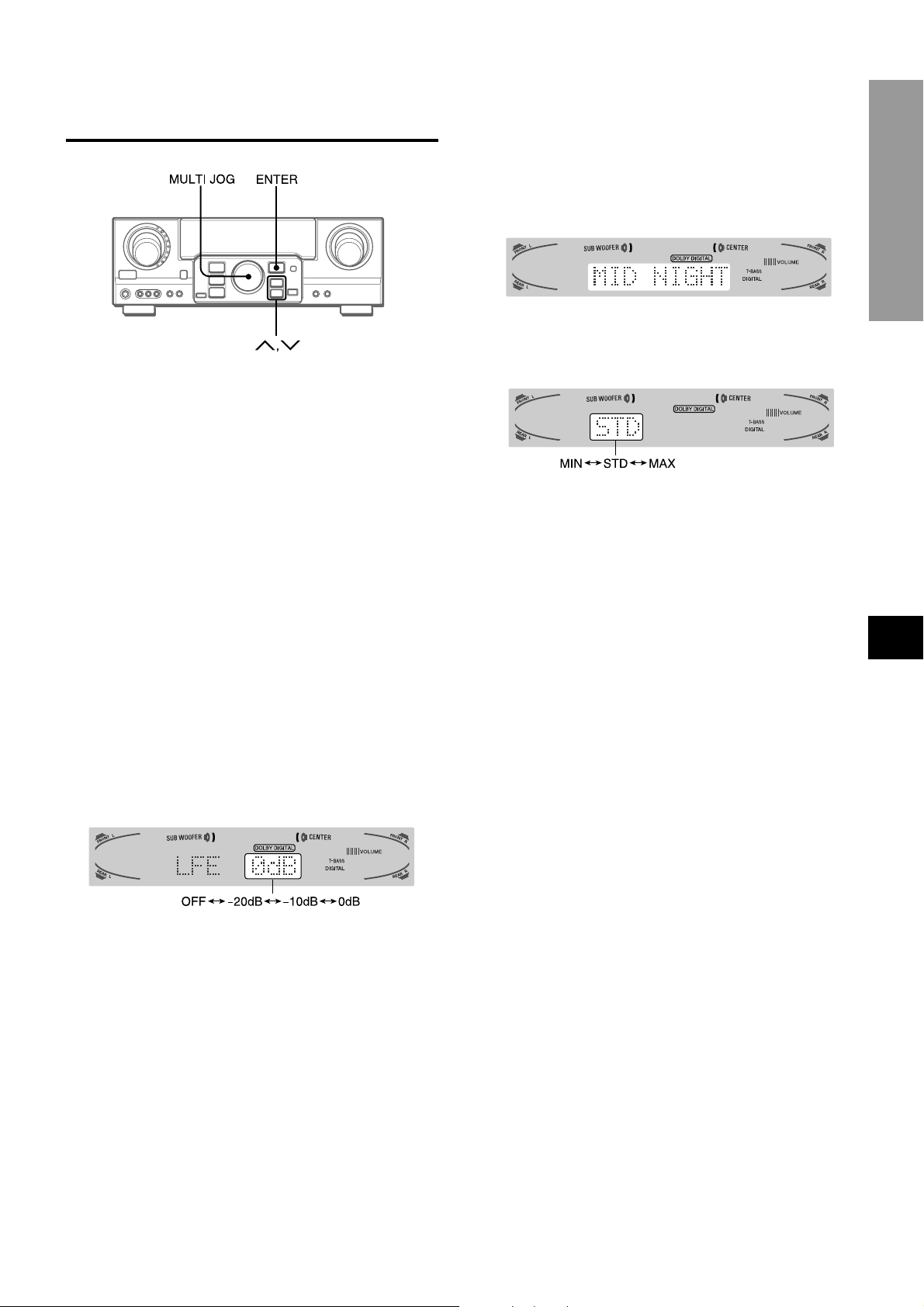
ADJUSTING DYNAMIC RANGE
Dynamic range of the Dolby Digital Surround sound can be
adjusted. The unit is initially set to the “STD” (standard) mode.
1 While the Dolby Digital Surround is activated,
press the ENTER button and hold it down until
“MID NIGHT THEATER” runs through on the
display.
2 Press the N or M button or turn the MULTI
JOG to select the “MAX,” “STD” or “MIN” mode.
[MIN]
You can enjoy the full dynamic range sound like in the movie
theater.
[STD]
Original position, when playing back in home, that is
recommended by the software producers.
[MAX]
Select this mode when playing back at low volume. This is
the mode used with the midnight setting.
EnEn
En
EnEn
DOLBY SURROUND
1 Press the N or M button and hold it down
until “LFE” is displayed.
2 Press the N or M button repeatedly or turn
the MULTI JOG to adjust the LFE level.
The unit is initially set to 0 dB (maximum) and can be adjusted
as shown below.
When selecting “SUBW OFF”, the LFE signals are redistributed
to other speakers.
EE
(Españo(Españo
E
(Españo
(Españo(Españo
EE
FF
(França (França
F
(França
(França (França
FF
ENGLISH
18
TIMER
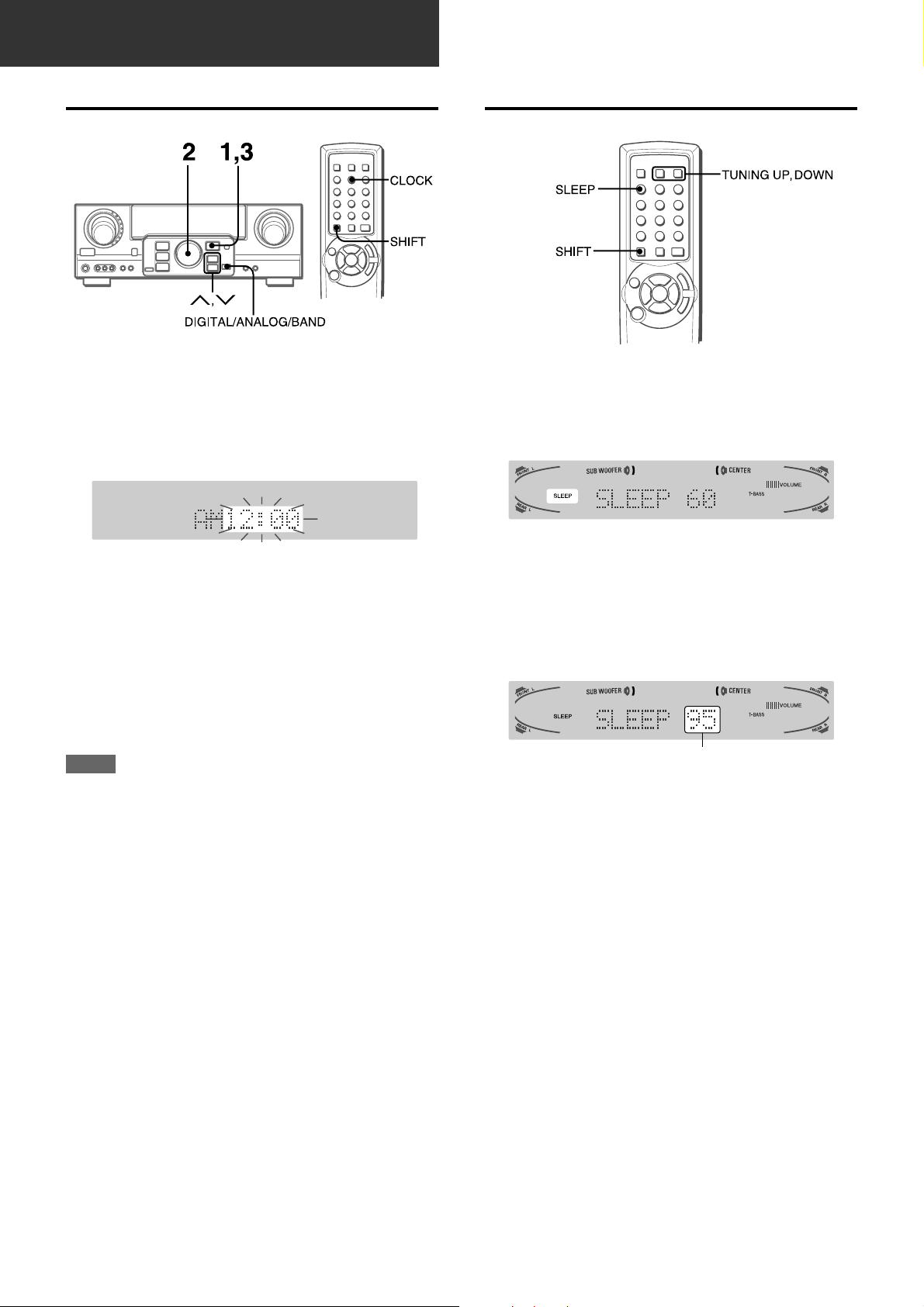
SETTING THE CLOCK
When the AC cord is connected for the first time, the clock on
the display flashes.
Set the time as follows while the power is off.
1 Press the ENTER button.
The display becomes a little brighter.
SETTING THE SLEEP TIMER
The receiver can be automatically turned off at a specified time.
Press the SLEEP button while pressing the SHIFT button
on the remote control.
2 Within 4 seconds, turn the MULTI JOG to
designate the hour and the minute.
The time advances by turning it to the right, and decreases
by turning it to the left.
The N or M button on the main unit is also av ailable. Press
the button repeatedly . To change the time rapidly in 10-minute
steps, hold it down.
3 Press the ENTER button.
The clock starts from 00 seconds.
NOTE
When the clock is set for the first time after purchase
Everything on the display will clear.
This is because the power economizing mode of the unit is
activated, and is not a malfunction.
The power economizing mode can be canceled. See page 7 f or
details.
To correct the current time
Press the POWER button to turn the unit off. Carry out steps 1
to 3 above.
To display the current time
Press the CLOCK button while pressing the SHIFT button on
the remote control. The clock is displayed for 4 seconds.
The unit will be turned off after about 60 minutes.
To specify the time until the power is turned off
Within 4 seconds after the above, press the TUNING DOWN or
UP button repeatedly while pressing the SHIFT button.
Y ou can change the time betw een 5 and 240 minutes in 5-minute
steps.
Specified time
To c heck the time remaining until the power is turned off
Press the SLEEP button once while pressing the SHIFT button.
The remaining time is displayed for four seconds.
To cancel the sleep timer
Press the SLEEP button twice while pressing the SHIFT button
so that “SLEEPoFF” appears on the display.
To switch to the 24-hour standard
Display the current time, and press the DIGITAL/ANALOG/BAND
button on the unit within 4 seconds.
Repeat the same procedure to restore the 12-hour standard.
In the 12-hour standard, “AM 12:00” indicates midnight and “PM
12:00” indicates noon.
If the clock display flashes while the power is off
This is caused by a power interruption. The current time needs
to be reset.
If power is interrupted for more than approximately 24 hours , all
settings stored in memory after purchase need to be reset.
19
ENGLISH
 Loading...