

Page 1
ROOM AIR CONDITIONER
INDOOR UNIT
AS24A2RC
AS18A6RC
AS18A0RCD
SERVICE
OUTDOOR UNIT
US24A2RC
US18A6RC
US18A0RCD
Manual
CONTENTSAIR CONDITIONER
1. Installation
2. Disassembly and Reassembly
3. Troubleshooting
4. Exploded Views and Parts List
5. Refrigerating Cycle Block Diagrams
6. PCB Diagrams
7. Wiring Diagrams
E DB81-00189A(3)
8. Schematic Diagrams
Page 2
1. Installation
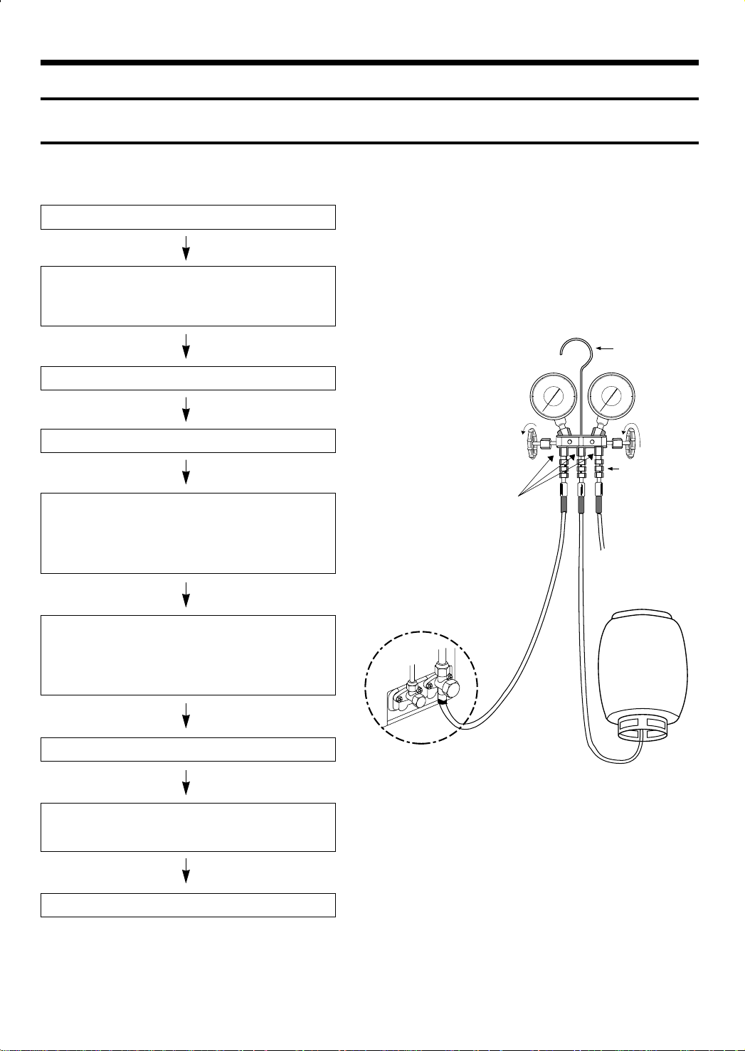
1-1 Refrigerant Refill Procedure
• Refill an air-conditioner with refrigerant when refrigerant has been leaked at installing or using
1. Purge air(for new installation only).
2. Turn the 3-way valve clockwise to close, connect the
pressure gauge(low pressure side) to the service valve,
and open the 3-way valve again.
Suspension hook
3. Connect the tank to refill with Refrigerant
4. Set the unit to cool operation mode.
5. Check the pressure indicated by the pressure
gauge(low pressure side).
* Standard pressure is should be 4.5~5.5kg/cm
regular, high operation mode.
6. Open the refrigerant tank and fill with refrigerant until
the rated pressure is reached.
* It is recommended not to pour the refrigerant in too
quickly, but gradually while operating a pressure valve.
7. Stop operation of the air conditioner.
2
in a
Compound
gauge
For mounting
other and of
hose when
not in use
High
pressure
gauge
Hand
wheel
Finger tight
fittings
Connected to
high pressure
side
Charging
line
R-22
8. Close the 3-way valve, disconnect the pressure gauge,
and open the 3-way valve again.
9. Close the cap of each valve.
1
Page 3
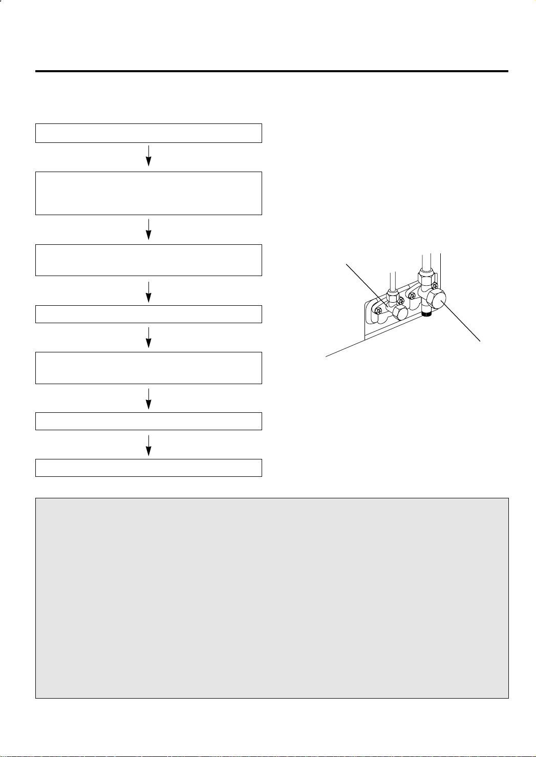
1-2 “Pump down” Procedure
Pump down' shall be carried out when an evaporator is replaced or when the unit is relocated in
another area.
1. Remove the caps from the 2-way valve and the 3-way valve.
2. Turn the 3-way valve clockwise to close and connect
a pressure gauge(low pressure side) to the service valve,
and open the 3-way valve again.
3. Set the unit to cool operation mode.
(Check if the compressor is operating.)
4. Turn the 2-way valve clockwise to close.
5. When the pressure gauge indicates "0" turn the 3-way valve
clockwise to close.
6. Stop operation of the air conditioner.
7. Close the cap of each valve.
Relocation of the air conditioner
• Refer to this procedure when the unit is
relocated.
1. Carry out the pump down procedure
(refer to the details of 'pump down').
2. Remove the power cord.
3. Disconnect the assembly cable from the
indoor and outdoor units.
4. Remove the flare nut connecting the
indoor unit and the pipe.
At this time, cover the pipe of the indoor
unit and the other pipe using a cap or
vinyl plug to avoid foreign material entering.
2-Way Valve
3-Way Valve
5. Disconnect the pipe connected to the outdoor unit.
At this time, cover the valve of the outdoor unit and the other pipe using a cap
or vinyl plug to avoid foreign material
entering.
6. Make sure you do not bend the connection
pipes in the middle and store together
with the cables.
7. Move the indoor and outdoor units to a
new locatioon.
8. Remove the mounting plate for the indoor
unit and move it to a new location.
2
Page 4
2. Disassembly and Reassembly
Stop operation of the air conditioner and remove the power cord before repairing the unit.
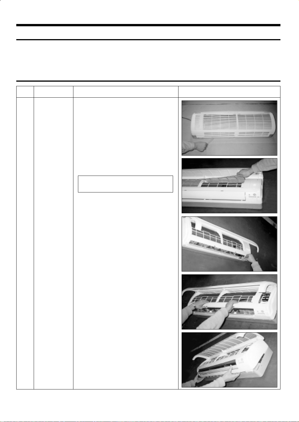
2-1 Indoor Unit
No Parts Procedure Remark
!
Front Grille 1) Stop the air conditioner operation and block the
main power.
2) Seperate tape of front panel upper.
3) Contract the second finger to the left, and right
handle and pull to open the inlet grille.
4) Take the left and right filter out.
* Take the Deodorizing and Electrostatic filter
out. (Optional)
5) Loosen one of the right fixing screw and seperate the terminal cover.
6) Loosen three fixing screws of front grille.
7) Pull the upper left, right and Center of discharge
softly for the outside cover to be pulled out.
8) Pull softly the lower part of discharge and push
it up.
Caution;
Assemble the front panel and fix the
hooks of left, right and Center
3
Page 5
No Parts Procedure Remark
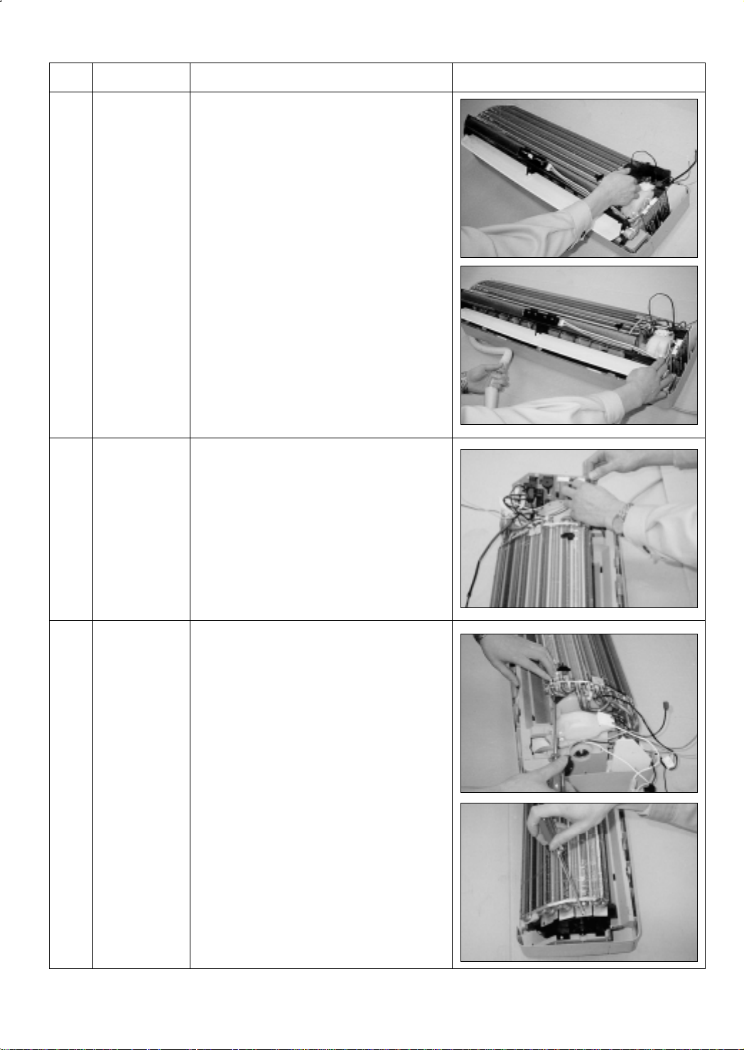
@
#
Ass’y Tray Drain.
Electrical Parts
(Main PCB)
1) Do “1” above.
Separate the drain hose from the extension
drain hose.
2) Take the display PCB out.
(Center of indoor unit)
3) Loosen two fixing screws of left and right
4) Pull tray drain out from the back body.
1) Do “1”, “2”, above
2) Take all the connector of PCB upper side out.
(Inclusion Power cord)
$
Heat Exchanger
3) Separate the outdoor unit connection wire from
the terminal block.
4) Pulling the Main PCB up. it will be taken out.
(Separate the TRANS hook. it before).
1) Do “1” and “2”, “3”, above
2) Loosen two fixing earth screws of right side.
3) Separate the connection pipe.
4) Separate the bush body at the upper side and
holder at the rear side.
5) Loosen the two fixing screws of left side.
6) Lifting the heat exchanger up a little to push the
up side for separation from the indoor unit.
4
Page 6
No Parts Procedure Remark
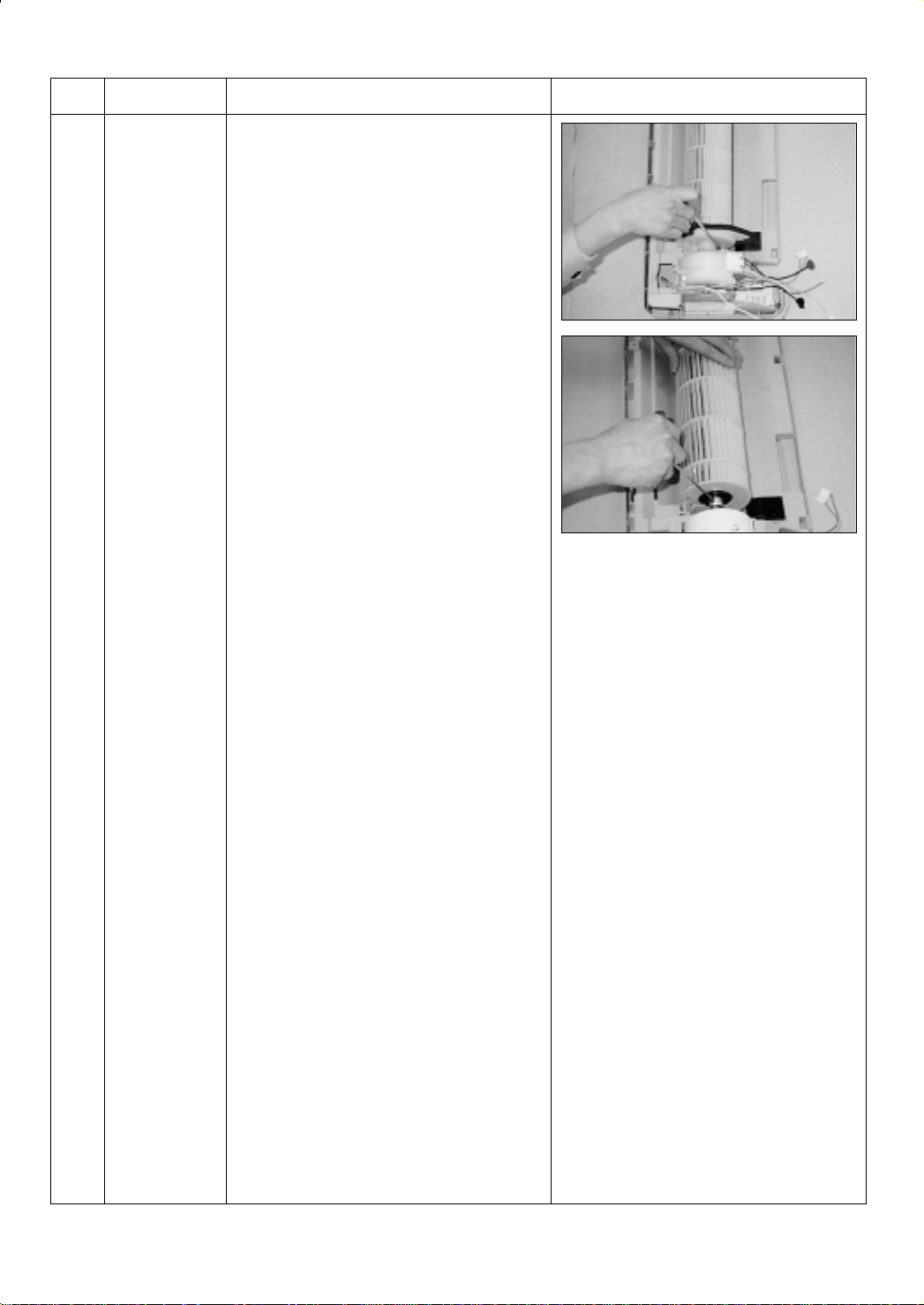
%
Fan Motor and
Cross Fan
1) Do “1” “2” ”3” “4”, above.
2) Loosen the fixing three screws and separate the
motor holder.
3) Loosen the fixing screw of fan motor.
(By use of M3 wrench)
4) Separate the fan motor from the fan.
5) Separate the fan from the left holder bearing.
5
Page 7
2-2 Outdoor Unit
No Parts Procedure Remark
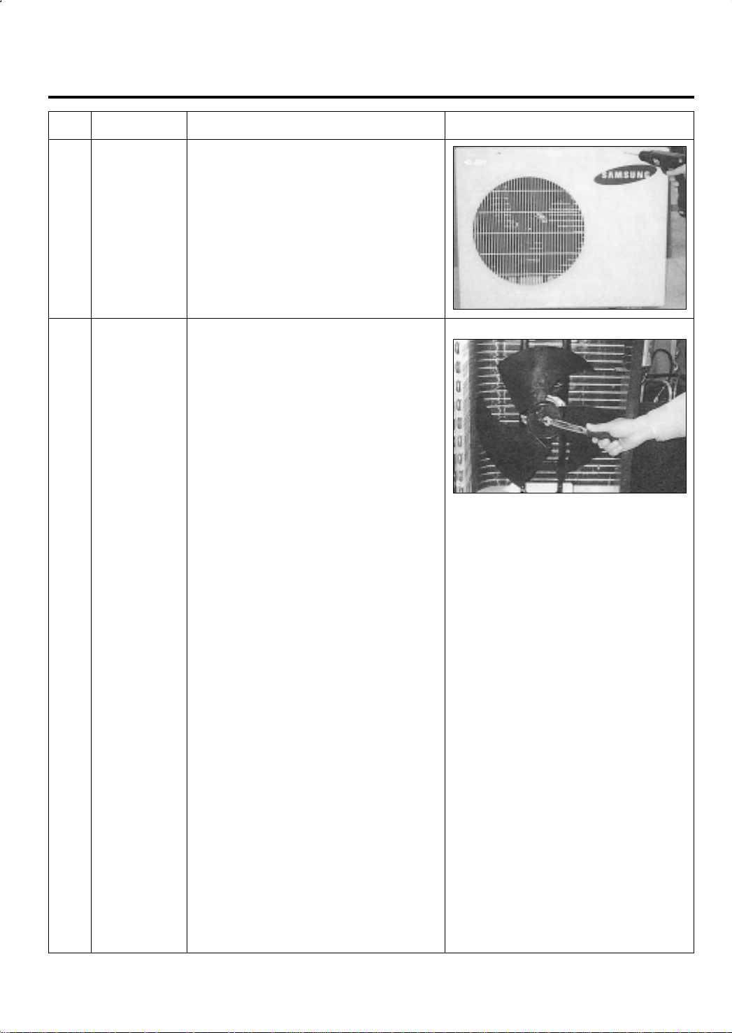
!
@
Cabinet
Fan Motor &
Propeller Fan
1) Turn off the unit and remove the power cable
2) Remove the top cover.
3) Remove the control box cover.
4) Unplug the ass'y cable.
5) Remove the cabi-side.
6) Remove the cabi-front.
* When you assemble the parts, check if the
each parts and electric connectors are fixed
firmly.
1) Do Procedure 1 above.
2) Remove the nut flange.
(Turn to the right to remove as it is a left turned
screw)
3) Disassemble the propeller fan.
6
Page 8
3. Troubleshooting
3-1 Items to be checked first
1) The input voltage should be rating voltage 10% range.
The airconditioner may not operate properly if the voltage is out of this range.
2) Is the link cable linking the indoor unit and the outdoor unit linked properly?
The indoor unit and the outdoor unit shall be linked by 6 cables.
Check the terminals if the indoor unit and outdoor unit are properly linked by the same number of
cables.
Otherwise the airconditioner may not operate properly.
3) When a problem occurs due to the contents illustrated in the table below it is a symptom not related to
the malfunction of the airconditioner.
NO
1 The STD operation indication LED blinks when a
power plug of the indoor unit is plugged in for the first time.
2 In a COOL operation mode, the compressor does not
operate at a room temperature higher than the setting
temperature that the INDOOR FAN should operate.
3 Fan speed setting is not allowed in AUTO or DRY mode.
4 Compressor stops operation intermittently in DRY mode.
5 The compressor stops intermittently in a COOL mode or DRY
mode, and fan speed of the indoor unit decreases.
4) Indoor unit observes operation condition of the air conditioner, and displays self diagnosis details on
the display panel.
NO
1 STD LED blinking (1Hz)
2 TIMER LED blinking (1Hz)
3 STD and TIMER LED blinking (1Hz)
4 BIO LED blinking (1Hz)
5 STD, BIO and TIMER LED blinking(1Hz)
6 All LED blinking(1Hz)
Operation of air conditioner
Display
Explanation
It indicates power is on. The LED stops blinking if the operation
ON/OFF button on the remote control unit is pushed.
In happens after a delay of 3 minutes when the compressor is
reoperated. The same phenomenon occurs when a power is on.
As a phenomenon that the compressor is reoperated after a delay of
3 minutes, the indoor fan is adjusted automatically with reference
to a temperature of the air blew
The speed of the indoor fan is set to LL in DRY mode.
Fan speed is 5 steps is selected automatically in AUTO mode.
Compressor operation is controlled automatically in DRY mode
depending on the room temperature and humidity.
The compressor stops intermittently or the fan speed of the indoor
unit decreases to prevent inside/outside air frozen depending on the
inside/outside air temperature.
Self Diagnosis
Restore from power failure (input initial power)
Indoor unit Room sensor Error (open or short)
Indoor unit heat exchanger temperature sensor Error (open or short)
Indoor fan malfunctioning (for spead is Below 450rpm)
EEPROM Error
Option Error (option wasn’t setup or option data error)
7
Page 9
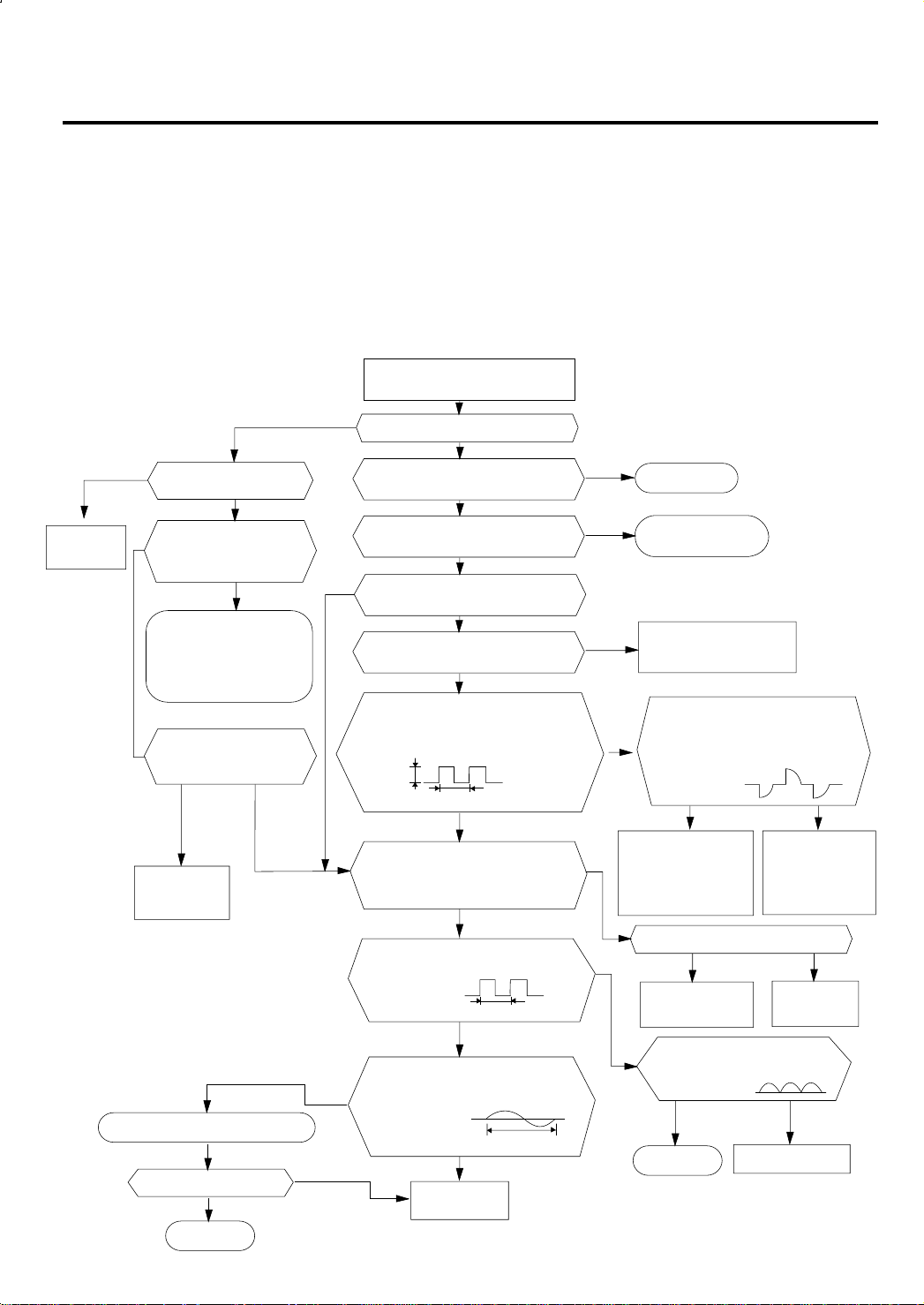
3-2 Fault Diagnosis by Symptom
3-2-1 No Power(completely dead)-Initial diagnosis
1) Checklist :
(1) Is input voltage normal? (rating voltage ±10% range)
(2) Is AC power linked correctly?
(3) Are connections between primary side, secondary side of the power transformer and PCB good.
(4) Is input voltage of DC regulator IC KA7805 (IC02) normal? (11VDC-12.5VDC)
(5) Is output voltage of DC regulator IC KA7805 (IC02) normal? (4.5VDC-5.5VDC)
2) Troubleshooting procedure
Remove power cord and plug in again
in approx. 5 seconds
YES
Replace PCB
display
8
Is DC voltage of PCB
display normal?
NO
Is the rating Voltage ±10%
range applied to the
between #1 and #3 of CN78
NO
•Check linkage between
power cord and
terminal tap
•Check fuse
Is 11~12.5VDC appear in
the input side of the DC
regulator IC KA7805(IC02)?
refer to
replace
PCB module
Replace resonator (X501)
Is operation normal?
YES
OK
NO
NO
YESNO
NO
NO
Is operation lamp blinking?
Does operation start when
run/stop button on the remote
controller unit pushed?
Is transmission display of the remote
controller unit blinking?
Is "beep"sound heard from the main
Is DC voltage of the PCB module
Are voltages of #8 (compressor), and#6
(outdoor fan) of the micom normal? ; 5VDC
Is voltage of #60 (indoor fan) of the micom
DC5V
Is voltage at #33 terminal of the Micom normal?
Is voltage at #18 terminal of the Micom normal?
Is voltage at #52 terminal of the micom
Are voltage at #48 and #49 of the
YES
NO
YES
unit?
YES
normal?
YES
normal?
10ms
NO
YES
normal?
10ms
YES
micom normal?
YES
Replace
micom
100ns
;
0VDC
;
5VDC
NO
YES
NO
NO
YES
NO
Normal
Refer to remote control
unit fault diagnosis
Refer to Replace PCB
module.
Are voltages at RY71(Compressor)
and RY72 (Outdoor fan)
Is voltage at SS71(indoor fan)
YES
Check connections
compressor, outdoor
fan and indoor fan.
Is output voltage of ICO2 normal?(DC5V)
YES
Refer to replace PCB
module
Is voltage output terminal of
D101~D105(IN4007) normal?
YES
OK
normal? ; DC12V
NO
Replace
RY71, RY72
and SS71
NO
Replace ICO2
NO
Replace IN4007
Page 10

3-2-2 When the Indoor Unit Fan Does Not Operate. (Initial Diagnosis)
1) Checklist :
(1) Is the indoor unit fan motor properly connected with the connector (CN73)?
(2) Is the AC voltage correct?
(3) Is HALL IC in indoor fan motor properly connected with the connector (CN43)?
(4) Is the running capacitor properly connected with the solder part of the PCB?
2) Troubleshooting procedure
After unplugging out the power cord should
Does the operating lamp(Green) blink?
Does the Solid State Relay(SS71) work
properly?
+
SS71+
PCB CN73
pin3, pin5
be reconnected within five seconds.
YES
YES
Test rod location
-
SS71-
YES
Is the supply voltage of the fan
motor sufficient?
Test rod location
Condition
Fan operate
12V
Normal
Voltage
Normal
voltage
.
= AC 180V
.
NO
NO
NO
Check as in the procedur “NO power parts”
Refer to page 8.
Microcomputer is out of order.
PCB is
out of order.
Refer to replace
PCB module
YES
Fan motor
is out of order.
MF-C is out of order
Replace MFC
Fan motor
should be replaced.
9
Page 11

3-2-3 When the Outdoor Unit Does Not Operate. (Initial Diagnosis)
1) Checklist :
(1) Is input voltage normal?(rating voltage ±10% range)
(2) Is the set temperature of the remote control higher than room temperature in COOL mode?
(3) Is the POWER IN connector (CN78) linked correctly?
(4) Is the outdoor unit properly connected with the TERMINAL BLOCK connector(5P)?
2) Troubleshooting procedure
After unplugging out the power cord should be recon-
nected within five seconds.
Does the operating lamp blink
YES
Does the timer lamp blink during operation ?
NO
Is the power relay RY71 operated by adjusting the room
temperature?
Test rod location Normal
+ - Condition Voltage
IC06 Pin #6 GND RY71 ON DC 4.8V
NO
Is the rating Voltage ±10% range applied relay between
CN78 ! and #.
NO
YES
YES
PCB and
Room tem-
perature
sensorshould
be checked.
!
!
NO
#
Check as in the procedure "No Power parts"
Room temperature sensor is
PCB is out of order.
Power relay is
out of order
Refer to page 8.
out of order
@
Power relay should be
Refer to replace
PCB module
replaced.
10
YES
!@
NO
Is the room sensor normal register?
(25°C → 10KΩ)
50˚F 68˚F 86˚F
17.96kΩ 12.09kΩ 8.3kΩ
YES
#
Outdoor unit is
out of order.
Page 12

3-2-4 When the UP/DOWN Louver Motor Does Not Operate. (Initial Diagnosis)
1) Checklist :
(1) Is input voltage normal? (rating voltage ±10% range)
(2) Is the UP/DOWN louver motor properly connected with the connector (CN61)?
2) Troubleshooting procedure
Remove power cord and plug in again in approx. 5 seconds.
NO
Is operating lamp blinking?
YES
Y
Does operation start when swing button of the remote
control unit pushed?
NO
N
Voltage at pin #1-#4 of micom (ICO4)
change?(Squarewave)
YES
Y
Volatge at pin #16, #15 of IC06, #10, #11 of IC05 (KID65003)
change?(Squarewave)
YES
Y
N
Check as in the procedure "No Power
parts". Refer to page 8.
YES
NO
NO
Y
N
N
Driver IC05 (KID65003) is faulty.
Normal
Micom (IC04) is faulty.
UP/DOWN louver motor is faulty.
11
Page 13

3-2-5 If Operation By Remote Control Unit Is Impossible. (Initial Diagnosis)
1) Troubleshooting procedure
Remove power cord and plug in again approx. 5 Seconds
Is operation lamp blinking?
YES
“ “ sound heard from the indoor unit when ON/OFF
button on the remote control unit pushed?
NO
Voltage of battery less than 2.5V (Remote Control Unit)?
NO
LCD display status of REMOCON normal?
YES
Transmission display lamp ( ) blinking when ON/OFF
button on the remote control unit pushed?
YES
Voltage at PIN #30 of Remocon Micom change?
YES
Voltage at collecter of Q601 or Q602 change?
YES
NO
Check as in the procedure “NO Power parts”.
Refer to page 8.
YES
YES
NO
NO
NO
NO
Q601(C4375Y) or Q602(C1623Y) is faulty.
Normal
Replace battery.
LCD is faulty.
Replace button.
Micom is faulty.
IR LED(CL-1L5EU) is faulty.
12
Voltage at pin #26 of micom (IC04) change (INDOOR UNIT)?
YES
Micom (IC04) is faulty.
NO
Receiver module is faulty.
Page 14

3-3 Replace PCB module
3-3-1 Replace PCB module
Replace the PCB module
Check the connection and plug in
Remove power cord
Does al display lamp blink or STD lamp blink?
YES
Refer to set up the Model option
NO
Replace another PCB module
13
Page 15

4. Exploded Views and Parts List
1
2
4
5
7-1
6
6-1
20
10-3
10-1
10-2
21
14
16
1112
13
9
8
13-1
17
18
19
10
15
7-2
3-2
3-3
3-1
3
7
4-1 Indoor Unit
14
Page 16

■ Parts List
No.
1
2
3
3-1
3-2
3-3
4
5
6
6-1
7
7-1
7-2
8
9
10
10-1
10-2
10-3
11
12
13
13-1
14
15
16
17
18
19
20
21
CODE NO
DB64-00127A
DB63-30150C
DB74-10101C
DB61-10164B
DB74-10082A
DB74-10081A
DB63-00091A
DB64-00130A
DB93-00311C
DB63-00115A
DB94-00099B
DB31-10153B
DB66-00104A
DB96-01125B
DB96-01125H
DB67-00058A
DB90-00884B
DB90-00433Z
DB61-00601A
DB65-10108A
DB65-00039H
DB65-00068C
DB31-10151D
DB94-00040J
DB94-40003A
DB94-40007A
PD-SH302C-01
PD-SH302C-03
DB32-00027B
DB61-10163A
DB94-00107A
DB90-00434A
DB70-10663A
DB63-00227A
DB70-00115A
Description Specification
GRILLE AIR INLET
GUARD AIR FILTER
CLEANER FILTER ASS´Y
CASE-CLEANER FILTER
DEODORIZING FILTER
CLEANER FILTER
COVER TERMINAL
FRONT PANEL
ASS´Y PCB DISPLAY
COVER DISPLAY
ASS´Y TRAY DRAIN
ASS´Y STEPING MOTOR
BLADE-H
ASS´Y EVAP
ASS´Y EVAP
SPACER-EVAP
ASS´Y HOLDER MOTOR(24K)
ASS´Y HOLDER MOTOR(18K)
HOLDER MOTOR
CLIP EARTH WIRE
TERMINAL BLOCK ASS´Y
TERMINAL BLOCK ASS´Y
MOTOR FAN IN
ASS´Y-CROSS FAN
RUBBER BEARING
BEARING MOTOR
ASS´Y MAIN PCB
ASS´Y- MAIN-PCB
ASS´Y-TERMISTOR
CASE CONTROL
ASS´Y BACK BODY
ASS´Y HOLDER PIPE
PLATE HANGER
COVER-TERMINAL BLOCK
PLATE-KNOCKOUT
HIPS
PP
ASS’Y
PP
POLYESTER/CARBON
POLYESTER/COTTON
ABS(V0)
HIPS
ASS’Y
ABC(BLK)
ASS´Y
MP24S
ABS
PLATE1.2(5/8”)
SLIT1.5(1/2”)
PVC
ASS’Y
ASS’Y
PP(Vo)
SECC
6P, 25A
6P, 25A
IIC-9430SKF7A
ø95 x L
CR(BLK)
ASS’Y
PD-SH30ZC-01
PD-SH30ZC-03
103AT
ABS(VO)
HIPS
ASS’Y
SGCC-M
ABS
SGCC-M
Q’TY
AS24A2RC AS18A6RC AS18A0RCD
1
2
1
2
1
1
1
1
1
1
1
1
1
1
1
1
1
1
1
1
1
1
1
1
1
1
1
1
1
1
1
1
2
1
2
1
1
1
1
1
1
1
1
1
1
1
1
1
1
1
1
1
1
1
1
1
1
1
1
1
1
1
2
1
2
1
1
1
1
1
1
1
1
1
1
1
1
1
1
1
1
1
1
1
1
1
1
1
1
1
1
1
15
Page 17

1
2
3
4
7
16
6
5
8
18
13
12
13-1
15-1
15-2
15-3
15-5
15
15-4
15-6
14-2
10
9
14-1
14
12-2
12-1
11
4-2 Outdoor Unit
4-2-1 24K BTU
17
17-1 17-2
16
Page 18

■ Parts List
No.
1
2
3
4
5
6
7
8
9
10
11
12
12-1
12-2
13
13-1
14
14-1
14-2
15
15-1
15-2
15-3
15-4
15-5
15-6
16
17-1
17-2
18
CODE NO
DB90-00652P
DB90-20210A
DB67-50074A
DB60-20020A
DB31-00027F
DB95-20147A
DB94-50039C
DB96-01917A
DB90-40176B
DB64-60160B
DB90-10616D
DB95-10339F
DB73-10008A
DB60-00028A
DB96-10637B
DB62-40055F
DB96-10635A
DB62-31842B
DB62-40039C
DB93-00680K
3501-001184
2501-001194
DB65-00040B
DB95-90026B
3601-000236
2501-000389
DB72-50622A
DB60-30010A
DB60-30010D
DB96-10670A
Description Specification Remark
Q’TY
US24A2RC
ASS’Y CABI FRONT
ASS’Y-BASE OUT
FAN-PROPELLER
BOLT SPECIAL
MOTOR FAN OUT
ASS’Y-MOTOR B/K
ASS’Y-PARTITION
ASS’Y-CONDENSER
ASS’Y-COVER-CONTROL
CABI SIDE OUT
ASS’Y-CABI UPPER
COMPRESSOR
GROMMET ISOLATOR
NUT WASHER
ASS’Y SUCTION
PACKED V/V 15.88"
ASS’Y-TUBE CAPI
TUBE CAPI(C)
PACKED V/V 6.35"
ASS’Y CONTROL OUT
POWER-RELAY
COMPOR CAPACITOR
TERMINAL BLOCK
SPARK KILLER
FUSE
MOTOR CAPACITOR
CLOTH SOUND
NUT FLANGE 6.35"
NUT FLANGE 15.88"
TUBE-DISCHARGE
SC-90073T
SC-90073T
AS+G/F20%
M8 L25
OSME-906SRC
SGCC-M
SGCC-M
ASS’Y
ABS(V5)
SC-90073T
SC-90073T
H29B26UABCA
CR
M8
ASS’Y
20LT/MIN
ASS’Y
ID 1.7 x 900 x 2
6.35 INCH
ASS’Y
UZ 2A BB220
35µFx450VAC
8P/35A
-
2A, 250V
4µF x 450VAC
G3771BD
G3771BD
-
1
1
1
1
1
1
1
1
1
1
1
1
4
4
1
1
1
1
1
1
1
1
1
1
1
1
2
2
1
17
Page 19

4-2-2 18K BTU(US18A✳RCD)
2
3
5
13-1
13
12-1
12-2
12
12-4
18
14
14-1
9
10
15-5
15-3
15-2
15-1
15-6
15-4
15
12-3
4
1
11
6
7
16
8
17
17-1 17-2
18
Page 20

15
14
10
9
12-2
12-1
13
13-1
18
5
3
2
4
11
1
6
7
16
8
12-4
12-3
15-2
15-1
15-3
15-5
15-4
15-6
12
If you need a receiver, install it at this point.
(The capacity is 255cc)
4-2-2 18K BTU(US18A✳RCD)
17
17-1 17-2
19
Page 21

■ Parts List
No.
1
2
3
4
5
6
7
8
9
10
11
12
13
13-1
14
14-1
15
15-1
15-2
15-3
15-4
15-5
15-6
16
17-1
17-2
18
CODE NO
DB90-00652K
DB90-00653K
DB90-20210B
DB90-20160H
DB67-50063A
DB60-20020A
DB31-10119H
DB31-00056D
DB61-20008C
DB94-00080A
DB94-00165A
DB96-01914A
DB96-01523B
DB90-40176B
DB90-60160B
DB90-10671L
DB90-00429A
DB90-10613D
48B190IV1EH
48D190IU1EH
DB96-00504A
DB96-01726A
DB62-40074C
DB62-00898B
DB96-00502B
DB96-10640B
DB62-40039B
DB93-01167B
DB93-00673N
3501-001184
2501-001238
DB65-00040B
DB95-90026B
3601-000236
2301-001370
DB72-50615A
DB60-30010A
DB60-30010D
DB60-30010C
DB96-00503A
DB96-01738A
Description Specification
ASS’Y-CABI FRONT
ASS’Y-CABI FRONT
ASS’Y-BASE OUT
ASS’Y-BASE OUT
FAN-PROPELLER
BLOT SPECIAL
MOTOR FAN OUT
MOTOR FAN OUT
MOTOR B/K BASE
ASS’Y-PARTITION
ASS’Y-PARTITION
ASS’Y-CONDENSER
ASS’Y-CONDENSER
COVER-CONTROL
ASS’Y-CABI BACK
ASS’Y-CABI BACK
ASS’Y-CABI UPPER
ASS’Y-CABI UPPER
COMPRESSOR
COMPRESSOR
ASS’Y-SUCTION
ASS’Y-SUCTION
PACKED V/V 12.7"
PACKED V/V 12.7"
ASS’Y-TUBE CAPI
ASS’Y-TUBE CAPI
PACKED V/V 6.35"
ASS’Y-CONTROL OUT
ASS’Y-CONTROL OUT
POWER RELAY
CAPACITOR COMP
TERMINAL BLOCK
SPARK KILLER
FUSE
CAPACITOR MOTOR
CLOTH SOUND
NUT FLARE 6.35"
NUT FLARE 15.88"
NUT FLARE 15.88"
TUBE-DISCHARGE
TUBE-DISCHARGE
SC-90073T
SC-90073T
SC-90073T
SC-90073T
AS+G/F20%
ASS035ZTEE
ASS030ZTEC
SGCC-M
ABS(V5)
SC-90073T
SC-90073T
48B190IV1EH
48D190IU1EH
10LT/MIN, 1/2"
10LT/MIN, 1/2"
6.35 INCH
UZ 2A BB220
40uFx450VAC
8P, 35A
2A, 250V
2.5uFx450VAC
C3771BD
C3771BD
C3771BD
M8L25
ASS’Y
ASS’Y
ASS’Y
ASS’Y
ASS’Y
ASS’Y
ASS’Y
ASS’Y
ASS’Y
ASS’Y
ASS’Y
ASS’Y
-
-
-
-
Q’TY
US18A6RC US18A0RCD
1
1
1
1
1
1
1
1
1
1
1
1
1
1
1
1
1
1
1
1
1
1
1
1
1
1
1
-
-
1
1
1
1
1
1
1
1
1
1
1
1
1
1
1
1
1
1
1
1
1
1
1
1
1
1
1
20
Page 22

4-2-3 PCB Box
4
1
2
5
3
■ Parts List
No
1
2
3
4
5
Description
ASS’Y MAIN PCB
ASS’Y THERMISTOR
ASS’Y PCB DISPLAY
CASE CONTROL
COVER DISPLAY
Specification
PD-SH30ZC-03
103AT 240/240
ASS’Y
ABS
ABS
Q’TY
1
1
1
1
1
Remark
21
Page 23

MEMO
22
Page 24

5. Refrigerating Cycle Block Diagram
INDOOR UNIT
Heat
exchanger
(Evaporator)
OUTDOOR UNIT
Capillary tube
1
T
Liquid side
Cross fan
2
T
Gas side
2-way valve
3-way valve
Compressor
Heat
exchanger
(Condenser)
Propeller fan
Cooling
Gas leak check point
Refrigerating cycle temperature and pressure
STD Pressure Piping Temp(°F) Use Temp. Condition(°F)
MODEL Operating Condition (psi)
3-Way Valve DB WB DB WB
T1 T2
Standard 57~71 46~54 46~54 80 67 95 75
AS24A2RC Cooling Max over load - - - 80 67 115 75
Low temp - - - 67 57 67 57
Standard 64~78 50~54 50~54 80 67 95 75
AS18A6RC Cooling Max over load - - - 80 67 115 75
Low temp - - - 67 57 67 57
Standard 64~78 50~54 50~54 80 67 95 75
AS18A0RCD Cooling Max over load - - - 80 67 115 75
Low temp - - - 67 57 67 57
Indoor Outdoor
23
Page 25

6. PCB Diagrams
6-1 Main PCB(PD-SH30ZC-03)
24
Page 26

■ Parts List
No. Design-Location Description Specification Q’TY
1 C103 C-CERAMIC,DISC 2.2nF,20%,400V,Y5U,TP,12. 1
2 C702 C-FILM,MPPF 100nF,10%,275V,BK,18x6x12,15 1
3 CR71 C-FILM,MPPF 2000nF,+10-5%,450V,BK,38x18x 1
4 C701 C-FILM,MPEF 220NF,10%,275V,BK,26.5X8.5X1 1
5 RY71,72,74 RELAY-MINIATURE 12VDC,200MW,3000MA,1FORM 3
6 SS71 SSR 12Vdc,-,2A,1mS,1mS 1
7 IC04 IC MICOM S3C8469(SDIP) 1
8 IC02 IC-VOLT REGU KA7805A,TO-220AB,1A,0/125C, 1
9 TN11 TRANS 2UEW0.30/2UEW0.45,1.5KV,1KHz,-,7Pi 1
10 FT71 CHOKE-COIL LSA-05230P,AC250V,2A,30.5x22x3 1
11 BZ61 BUZZER CBE2220BA,STICK,-,-,-,-,-,-,- 1
12 F701 FUSE FST,250V,3.15A,20MM,VDE,50T-03 1
13 F701 HOLDER-FUSE FH-51H,7.5A,-,-,-,-,- 1
14 D101,102,103,104 DIODE-RECTIFIER 1N4007,1000V,1A,DO-41,TP 4
15 D105 DIODE-RECTIFIER UG2B,100V,2A,DO-204AC,TP 1
16 ZD12 DIODE-ZENER DIODE-ZENER;MTZ3.6A,3.6V,3.455-3.695V,50 1
17 ZD13 DIODE-ZENER DIODE-ZENER;MTZJ11B,11V,10.5-11.05V,500m 1
18 ZD11 DIODE-TVS DIODE-TVS;ST02D-200,185/200/215V,200W,DO 1
19 Q603 TR-SMALLSIGNAL TR-SMALL SIGNAL;KSA708-Y,PNP,800mW,TO-92 1
20 Q401,601,602 TR-SMALL SIGNAL TR-SMALL SIGNAL;KSC945,NPN,250mW,TO-92,T 3
21 Q901,902 TR-DIGITAL TR-DIGITAL;KSR2002,PNP,300MW,10K/10K,TO- 2
22 Q201 TR-DIGITAL TR-DIGITAL;KSR1002,NPN,300MW,10K/10K,TO- 1
23 PC11 PHOTO-COUPLER PHOTO-COUPLER;TR,50-600%,200mW,DIP-4,ST 1
24 PC12 PHOTO-COUPLER PHOTO-COUPLER;TR,20-300%,200mW,DIP-4,ST 1
25 IC01 IC-PWM CONTROLLER IC-PWM CONTROLLER;255,DIP,8P,300MIL,PLAS 1
26 VA71,72 VARISTOR 560V,2500A,17.5x7.5mm,TP 2
27 R405,406 R-CARBON 330ohm,5%,1/8W,AA,TP,1.8x3.2mm 2
28 R104,105 R-CARBON 220OHM,5%,1/4W,AA,TP,2.4X6.4MM 2
29 R101 R-CARBON 470OHM,5%,1/4W,AA,TP,2.4X6.4MM 1
30 R206,501,502,601,604,606,902 R-CARBON 10KOHM,5%,1/8W,AA,TP,1.8X3.2MM 7
31 R201,207,208,401,403,408,603,605,608 R-CARBON 1KOHM,5%,1/8W,AA,TP,1.8X3.2MM 9
32 R910,911,912,913 R-CARBON 3.3KOHM,5%,1/8W,AA,TP,1.8X3.2MM 4
33 R102,103 R-CARBON 330KOHM,5%,1/4W,AA,TP,2.4X6.4MM 2
34 R106,901 R-CARBON 4.7KOHM,5%,1/8W,AA,TP,1.8X3.2MM 2
35 R607 R-CARBON 560OHM,5%,1/4W,AA,TP,2.4X6.4MM 1
36 R402 R-CARBON 6.8KOHM,5%,1/8W,AA,TP,1.8X3.2MM 1
37 R602 R-CARBON(S) 1KOHM,5%,1/2W,AA,TP,2.4X6.4M 1
38 R202,203 R-METAL OXIDE(S) 51Kohm,5%,2W,AA,TP,4x12 2
39 R404,407 R-METAL 6.8Kohm,1%,1/8W,AA,TP,1.8x3.2m 2
40 C203,204,401 C-CERAMIC,MLC-AXIAL 10nF,+80-20%,25V,Y5V 3
41 C404,903 C-CERAMIC,MLC-AXIAL 1nF,10%,50V,Y5P,TP,1 2
42 C102,104,107,109,114,116,117,118,201, C-CERAMIC,MLC-AXIAL 100nF,+80-20%,50V,Y5 14
202,402,403,501,901
43 C105 C-AL 1000uF,20%,25V,GP,TP,10x20,5 1
44 C601 C-AL 47uF,20%,50V,GP,TP,6.3x11,2.5 1
45 C108 C-AL 470uF,20%,25V,GP,TP,10x16,5 1
46 C101,110 C-AL 6.8uF,20%,450V,GP,TP,10x16mm,5 2
47 X501 RESONATOR-CERAMIC 4MHz,0.5%,TP,10.0x5.0x 1
48 F702 FUSE-RADIAL LEAD 250V,1A,TIME-LAG,-,8.5x 1
49 CN78 CONNECTOR-HEADER 1WALL,3P/5P,1R,3.96mm,S 1
50 CN71 CONNECTOR-HEADER 1WALL,3P/5P,1R,3.96mm,S 1
51 CN73 CONNECTOR-HEADER 1WALL,3P/5P,1R,3.96mm,S 1
52 CN91 CONNECTOR-HEADER BOX,10P,1R,2.5mm,STRAIG 1
53 CN43 CONNECTOR-HEADER BOX,3P,1R,2.5mm,STRAIGH 1
54 CN41 CONNECTOR-HEADER BOX,4P,1R,2.5mm,STRAIGH 1
55 CN61 CONNECTOR-HEADER BOX,6P,1R,2.5mm,STRAIGH 1
56 IC07 IC-MASK ROM 93LC56B,8BIT,-,DIP,8P,-,-,- 1
57 IC03 IC-RESET KA7533,DIP,-,-,-,-,- 1
58 IC06 IC-DRIVE KID65003AP,DIP,16P,STICK,TR-AR 2
59 L101 COIL CHOKE 5.0mH,-,8.0*11.0,-,-,PE-M10 1
60 WIRE-SO COPPER PI0.6,SN,T,52MM,TAPING_WI 35
61 PCB-MAIN PD-SH30ZC-00,FR-1,-,-,T1.6,W197 1
25
Page 27

7. Wiring Diagrams
7-1 Indoor Unit
■ AS24A2RC/AS18A0RCD ■ AS18A6RC
26
Page 28

7-2 Outdoor Unit
■ US24A2RC/US18A0RCD
DIAGRAM-OUTDOOR
MARK NAME MARK NAME
PR POWER RELAY TB 1, 2 TERMINAL BLOCK
C1 CAPACITOR FM1 FAN MOTOR
F FUSE(2A, 250V~) S SPARK KILLER
■ US18A6RC
DIAGRAM-OUTDOOR
MARK NAME MARK NAME
PR POWER RELAY TB1, 2 TERMINAL BLOCK
F FUSE(2A, 250V~) FM1 FAN MOTOR
S SPARK KILLER
27
Page 29

8. Schematic Diagrams
8-1 Indoor Unit
2928
Page 30

MEMO
30
Page 31

MEMO
31
Page 32

MEMO
32
Page 33

ELECTRONICS
 Loading...