

SONY AN5163K Service Manual
AN498
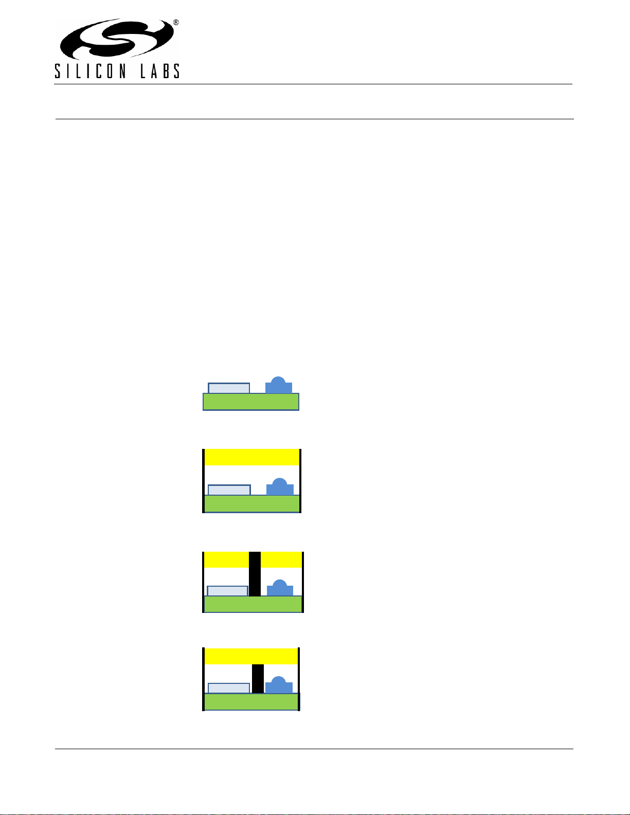
Emitter and sensor are
underneath one overlay,
but with an optical block
in-between. The Hybrid is
essentially a Single-port
with optical blocking
d) Hybrid
Emitter and sensor are in
separate compartments,
each compartment has a
separate overlay.
c) Dual Port
Sensor and emitter
underneath a single
compartment, single
overlay
y
Si114X DESIGNER’S GUIDE
1. Introduction
This application note provides an outline for using the Si114x proximity detector and ambient-light sensor. General
considerations of electrical and optical component selection, programming, and power consumption are explained
so as to cover the majority of situations. Specific topics are discusse d els ewh e re:
AN521: IRLED Selection Guide for Si114x Proximity Applications
AN522: Using the Si1141 for Touchless Lavatory Appliances
AN523: Overlay Considerations for the Si114x Sensor
AN540: Hair Immune Cheek Detection in SmartPhones Using the Si1141 Infrared Sensor
AN541: Smoke Detection using the C8051F990 and Si1141
AN580: Infrared Gesture Sensing
2. Optical Considerations toward Mechanical Design
This section focuses on mechanical and industrial design considerations.
2.1. Topology
Figure 1 highlights and defines the various system topologies.
Si114
irLED
No Overla
a) No Port
b) Single Port
Overlay
Si114
Si114
Overlay
Overlay
irLED
irLED
Figure 1. System Topologies
Rev. 0.6 10/11 Copyright © 2011 by Silicon Laboratories AN498
AN498
Si114x
Si114x
Optical
No Port
Single Port
Si114x
irLED
Overlay
•
Single overlay in hybrid is a medium for secondary sources of
light leakage from irLED compartment to sensor compartment.
• Dual Port is recommended for long range targets where
PS_ADC_GAIN needs to be increased.
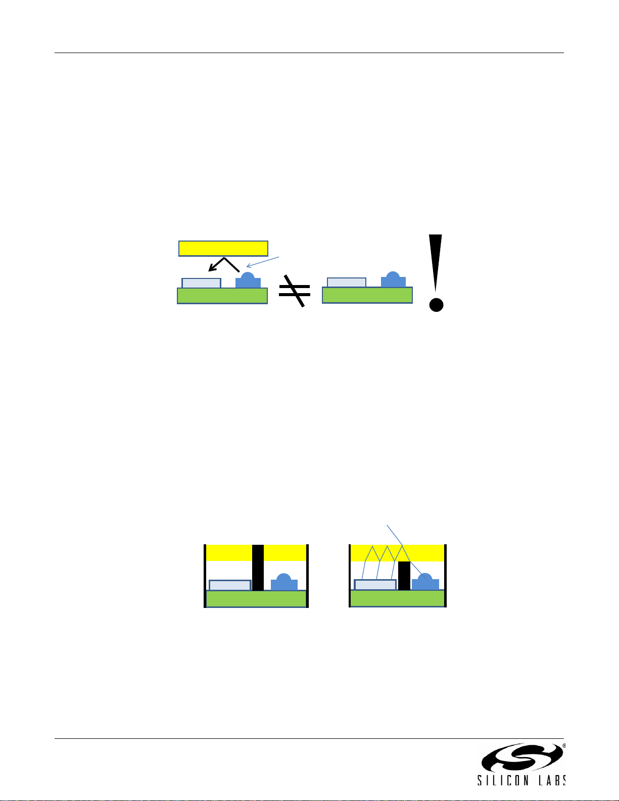
The purpose of the system topologies disc ussed is to provide a sense of the level of optical leakage or cross-talk
expected in a proximity system. One common misconception is that a system without an overlay and one with a
transparent overlay are “the same”. Although they might appear the same to the human eye, it is important to
examine this from the perspective of the device.
2.2. Optical Leakage
Also refer to "4. Proximity Measurements" on page 26 for information on how the Si114x makes Proximity Sense
(PS) measurements.
Even if the overlay is clear, these
systems are NOT equivalent
Overlay
Leakage
irLED
irLED
Figure 2. Common Misconception
In a Single-Port system, there exists a reflection from the overlay. The magnitude of the reflection is a function of
the index of refraction and the incident angle relative to the overlay surface normal. There is a set of equations
called 'Fresnel's Equations' that provides a prediction as to the amount of light reflected back to the sensor.
In a No-Port system, the optical leakage from the overlay is not present. However, this does not mean that optical
leakage does not exist. There may be optical paths causing the optical leakage other than the overlay.
The most common topology used in cell-phones and hand-held devices is actually a hybrid between the SinglePort and the Dual-Port. The Dual-Port distinguishes itself from the Hybrid in that irLED and the sensors are fully
compartmentalized, even to the point that two sep arate overlays are used.
In the Hybrid topology, the overlay itself becomes a medium for optical leakage. Light transfers from one
compartment to the other through internal overlay reflections. The Hybrid topology can approach the optical
performance of the Dual-port system topology. For systems requiring the highest ADC sensitivity, the host may
need to choose a higher PS_ADC_GAIN setting. To be able to use the settings with high PS_ADC_GAIN settings,
the optical leakage must be carefully controlled.
Overlay
Dual Port Hybrid
Figure 3. Dual Port vs. Hybrid Topology
2 Rev. 0.6
Overlay
AN498
Overlay
Target
Optical
Leakage
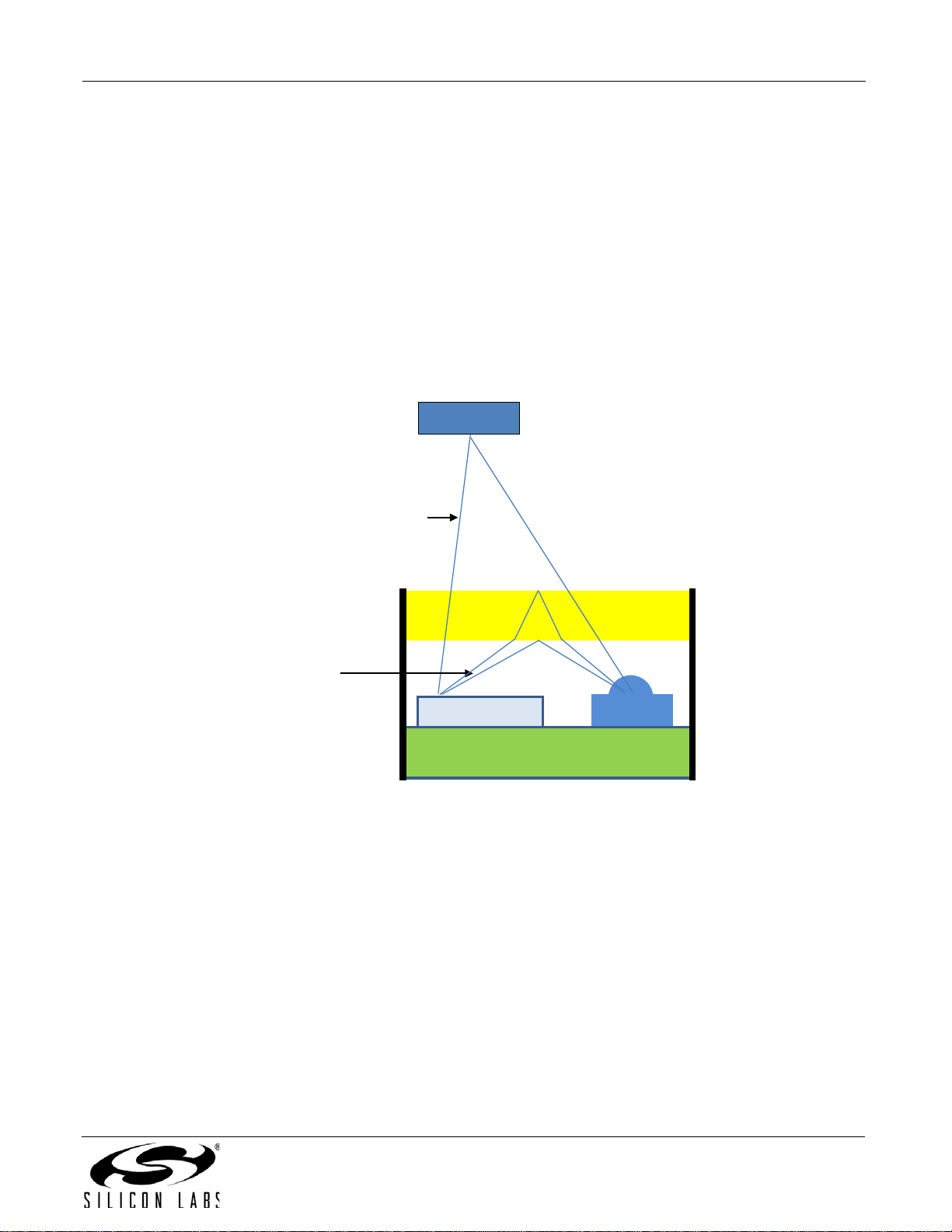
Optical leakage is also sometimes called “crosstalk”. A proximity detector aims to measure the increase in light
levels caused by turning on the irLED. Ideally, only light reflected from the target will reach the sensor. Figure 4
illustrates two light rays, each hitting the Si114x photodiode. In Figure 4, note that there are three light rays
originating from the irLED. One of these light rays is shown to hit the Target. The target is assumed to be a diffuse
surface and radiates in all directions. When one of those rays falls onto the Si114x photodiode, it increases the
ADC reading proportional to the level of reflectance emitted by the target.
Figure 4 also shows an additional two light rays originating from the irLED. These two rays do not hi t the t a rget, b ut
instead hit the overlay. One light ray hits the top of the overlay surface (refraction is illustrated); the other hits the
bottom of the overlay. A specular reflection is essentially a mirror-surface where the light ray is reflected at a very
specific angle. In a specular reflection, the incident angle equals the reflected angle.
In Single-Port topologies, it is not unusua l for the optical leakage to exceed the reflectance from the target. The
optical leakage eats into the ADC Dynamic Range and may force the use of a less-sensitive ADC setting. A
consequence of using a less-sensitive ADC setting is that it may require the use of a higher irLED current to detect
the target object at the cost of higher power consumption.
Target
Reflectance
Si114x
Figure 4. Optical Leakage
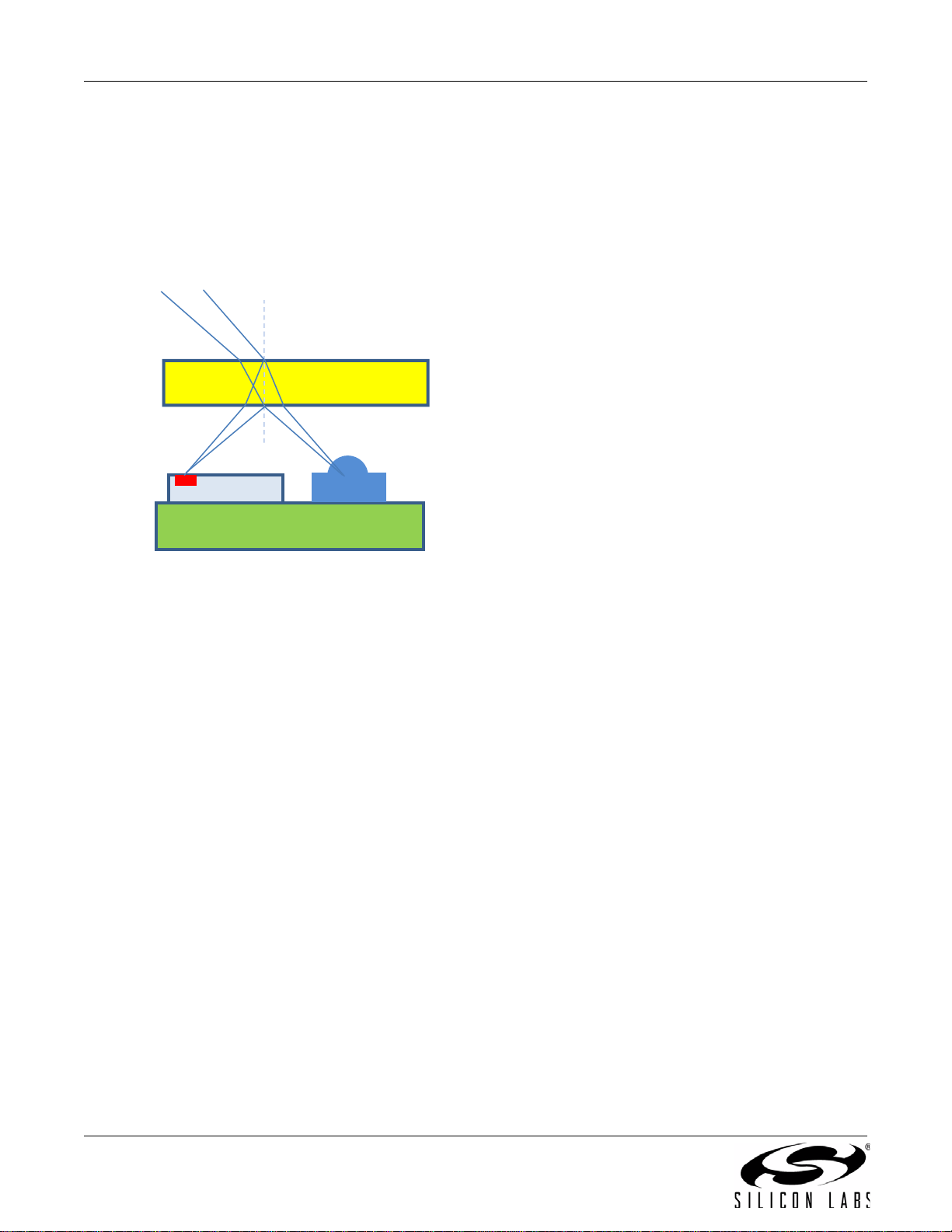
The greatest source of optical leakage is the specular reflection from the overlay. For this light ray, the radiant
intensity of the irLED given the radiation angle, the reflection coef ficient (function o f the overlay's index o f refraction
and incident angle), and the travel distance (inverse square relationship) all combine to form the dominant leakage
path. The overlay contains two surfaces, resulting in two rays hitting the photodiode. These two rays are roughly
equal in magnitude; it is, therefore, important to block both of these rays.
Reducing the leakage from these two primary paths can also be achieved by pla cing the irLED close to the overlay.
This way, only light rays with very steep angles relative to the axial direction are allowed to originate from the
irLED. The radiant intensity is typically a function of the radiation angle, and a higher radiation angle generally has
a lower radiant intensity.
In addition to the primary leakage paths, there are other sources of optical leakage to consider. Unlike the primary
leakage paths, where there is only a single reflection point prior to directing to the sensor, the rays of the secondary
leakage paths generally take multip le bounces to get to the sensor.
For example, a light ray can bounce off the overlay and strike the PCB. The PCB can then reflect the ray as a
diffuse surface, causing a small portion of that reflection to reach the Si114x photodiode through yet another
specular reflection. Of course, the radiant power decreases with each bounce.
irLED
Rev. 0.6 3
AN498
Both inner and outer overlay
surfaces reflect incident light
• The reflection coefficient is
described by Fresnel’s Equations.
It is a function of the incident
angle and the overlay’s index of
refraction.
•
PCB has high IR transmittance. Copper (e.g. ground fill) is IR-opaque.
• Minimize the distance from top of irLED to bottom of overlay.
• irLED radiation pattern (radiant intensity vs angle) is an important
consideration.
The PCB has a high transmittance to IR, but it is not obvious to the human eye since the PCB looks opaque. Use
copper ground fill to make the PCB opaque to IR.
The irLED choice is also an important considera tion. When an irLED has a wide radia tion p attern, there is le ss light
focused at the angles close to the axial direction. What this means is that there is more light radiated outwards at
steep angles. The total light power becomes directed towards optical leakage. With more light energy in these
steep angles, the more light there is to feed the secon dary leakage paths. Choosing an irLED with a na rrow halfangle leads generally leads to lower system optical leakage in addition to better overall proximity detection
distance.
Si114x
PCB
Overlay
•
irLED
Figure 5. Optical Leakage Summary
4 Rev. 0.6
AN498
10 meters
5 cm
Tr a n smitta n ce < 0.0 5
10
2
2
Optical Block Material under Test
Ma ke sure remo te control wo rks
R emote control does not work
2.3. Optical/Mechanical Components
2.3.1. Optical Blocking Material
An Si114x proximity system uses the “near infrared” wavelengths. As such, many objects that look black are
candidates for optical blocking material.
Natural Rubber is a common material known to be opaque to visible light and the near-infrared band. Another
property of Natural Rubber that makes it suitable for optical blocking is its elasticity. Commercially-available rubber
sheets can be cut to size for optical blocking. For example:
www.rubbersheetroll.com/rubber-sheets.htm
Nitrile Rubber or “Buna-N” O-rings are used for optical blocking in Silicon Labs' evaluation platform and can be
found at the following web site:
www.mcmaster.com/#4061t111/=9ujxqp
If an adhesive thin-sheet back device is desired, a polyurethane foam material from 3M (Bumpon™) can be used
as an optical blocking material:
search.digikey.com/scripts/DkSearch/dksus.dll?vendor=0&keywords=bumpon+roll
There are more IR-opaque materials available than are discussed in this document. However, since many visibleopaque materials are not necessarily IR-opaque, it is best that materials be characterized by IR opacity. The
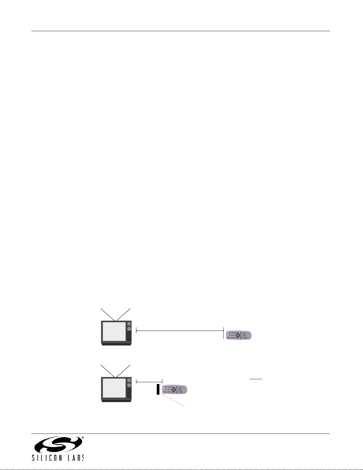
easiest method of checking the infrared opacity of a material is with a television remote control:
1. Find a common TV remote control.
2. Verify that the TV remote control is able to control the television.
3. Note the maximum distance that the TV remote control operates.
4. Locate the location of the IR sensor on the TV.
5. Verify that this is the IR sensor correct by placing the TV remote control directly on top of the IR sensor.
6. Cover the material in front of the TV remote control.
7. Attempt to control the TV.
8. If the material is opaque to the near infrared band, then, you should not be able to operate the TV even if the
remote control is positioned right up to the IR sensor window.
It is possible to determine infrared opacity by calculating the maximum transmittance of the material using this
procedure. For example, if the TV remote control is able to operate at a distance of 10 meters, and the optical
blocking material made it impossib le f or th e T V r em o te co nt ro l to op e rate even when it is only 5 cm away, then the
transmittance of the material is, at most, .000025. This indicates that the material is opaque to the near infrared
spectrum.
Figure 6. Infrared Opacity Test
Rev. 0.6 5
AN498
Overlay
PC B
Use co pper ground fill to blo ck leakag e
D
Si1 14x
2.3.2. Infrared Properties of Printed Circuit Boards
Many materials that appear visibly opaque to the human eye can have a high transmittance to infrared
wavelengths. Printed Circuit Boards, for example, have high transmittance to near infrared light. Therefore, it is
important to also consider Printed Circuit Boards as optical components.
The copper layers of printed circuit boards are opaque to infrared light. Maximizing the amount of copper
underneath the irLED and the Si114x is an effective method of reducing the amount of optical leakage through the
PCB material.
irLE
Figure 7. PCB has High IR Transmittance
2.3.3. Choosing an Overlay
The Si114x does not require any optical filter for proper operation.
Electrical engineers are familiar with the terms “High Pass Filter” and “Low Pass Filter”. In optics, there are
commonly-used analogous terms for describing overlays.
“Long Pass Filter” refers to a material that allows long wavelengths to pass through while disallowing short
wavelengths.
“Short Pass Filter” refers to a material that allows short wavelengths to pass through while disallowing longer
wavelengths.
As a reference, purple light is at 400 nm; green light is 550 nm; red light is 700 nm, and the infrared light typically
chosen for proximity is 850 nm.
6 Rev. 0.6

AN498
Shortpass Filter
Longpass Filter
550 550850 850
Figure 8. Shortpass Filter vs. Longpass Filter
A “Long Pass Filter” with a corner wavelength of 700 nm blocks visible light while allowing the infrared spectrum to
pass through. The opposite of a long pass filter is the short pass filter. So, a short pass filter with a 700 nm corner
wavelength allows visible light while blocking the infrared spectrum.
In general, there is a desire for most products to hide internal electronics from visible view. Common materials and
inks generally have a higher transmittance to in frared light compared to visible light . For th e most part, this me ans
that there is a tendency to having the overlay act more as a “long pass filter” than a “short pass filter”, since a
design goal of many products is to obstruct visible light from the view of human users.
Let us stop for a moment and consider “what is the signal” being measured in a proximity sensing application and
an ambient light sensor.
In the case of a proximity sensing application, the “signal” is 850 nm infrared light emitted from the irLED. In a
Proximity Sense (PS) only application, if the overlay blocks everything except 850 nm ±30 nm, the system will
operate.
Rev. 0.6 7

AN498
In an ambient light application usage where there is a desire to measure the visible ambient light, the “signal” are
the wavelengths between 400 nm to 700 nm. From the perspective of an ambient light sensing application, any
spectral reading above 700 nm and any spectral reading below 400 nm are “noise”. A “bandpass filter” that is
shaped in the form of a human eye response is called a “photopic” filter.
Hiding the internal electronics from view somewhat conflicts with the concept of “maximizing the signal” for ALS
usage.
2.3.3.1. Overlay Considerations
In proximity-only applications, the “signal” is the light of the wavelength emitted from the irLED (e.g. 850 nm).
Obviously, if the transmittance at the irLED wavelength is low, then much of the light from the irLED is absorbed by
the overlay, leading to lower performance.
Since there is often a “t arget ob ject distance” consideration, a significant optical overlay loss can translate to a loss
in sensitivity with target object distance unless the overlay loss is compensated for with a different irLED or higher
irLED current.
For a proximity-only application, aside from aesthetic reasons or industrial design constraints, maximizing the
850 nm transmittance should be the design goal. For applications requiring the highest performance under direct
sunlight, a bandpass overlay allowing a narrow band of wavelengths around 850 nm provides the best
performance.
The following common overlay approaches are possible with the Si114x. They are listed in order of preference by
performance.
Clear plastic or glass overlay
Clear overlay with ink applied through a silkscreen process
Colored plastic or glass overlay
The choice of the overlay is often an industrial design decision.
Many applications opt to start with a clear overlay material and screen-print the desired pattern using special inks.
Refer to "3.7. Selecting RLED" on page 25 .
Note that even if an overlay has a relatively low IR transmittance, this does not necessarily mean that the Si114x
will not work with such an overlay. The overlay transmittance is merely one of many system factors that come into
play .
For example, if the system must operate under low IR transmittance overlays, then the following system-level
tradeoffs include:
Reducing target object distance
Increase irLED current
Higher efficiency irLED
Narrower irLED half-angle
Typically, the irLED choice can compensate for overlay transmittance loss.
A simple procedure using a common TV remote control can be used to determine the transmittance of the overlay
material. Although the transmittance of the TV remo te control measures the transmittance at 940 nm, the estimate
is often sufficiently close to the transmittance at 850 nm.
1. Find a common TV remote control.
2. Verify that the TV remote control is able to control the television.
3. Note the maximum distance at which the TV remote control operates but begins to fail to control the TV (the
boundary of operation).
4. Locate the IR sensor on the TV.
5. Verify that this is the IR sensor by placing the TV remote control directly on top of the IR sensor.
6. Cover the TV remote control with the overlay material.
7. Attempt to control the TV, noting the boundary of operation.
8. The ratio of the distance squared is the IR transmittance.
8 Rev. 0.6

AN498
10 meters
9 m et er s
Tr a n smit tance = 9
10
2
2
O verlay Material u nder Test
De term ine distan c e where
remote c ontrol begins to fail
D eterm ine distan c e whe re
remote c ontrol begins to fail
Figure 9. Estimating Overlay Transmittance
Once the IR transmittance is estimated, the estimate can be considered when choosing an irLED and its current. It
is generally possible, with the correct choice of irLED and irLED current, for the target object to be detected despite
the overlay transmittance. Refer to “AN521: irLED Selection Guide for Si114x Proximity Applications”.
In an application that also includes ALS, wavelengths in the visible light spectrum (4 00 nm to 700 nm) are now part
of the “signal”. Better performance is achieved in any system by maximizing the signal.
Due to the typical system goal of obscuring electronics from view, there is a tendency to use an overlay that has a
low transmittance of visible light. Since visible light is also p ar t of the signal to be measured, it is n o longer po ssible
to simply use a visible-light-opaque material.
A balance must be maintained between the goals of obscuring electronics from visible s ight versus allowing in
sufficient light to measure the visible ambient light. In general, an overlay that allows 5% to 10% of visible light is
recommended. A 5% to 10% transmittance should allow the electronics to be virtually invisible under most
conditions, while still allowing sufficient light for proper ALS operation.
“AN523: Overlay Considerations for the Si114x Sensor” provides additional information in choosing an overlay.
AN523 also provides the lux calculation coefficients needed for some overlays.
2.3.3.2. Clear Acrylic and Polycarbonate Sheets
Clear acrylic material is generally available. A common trade name for acrylic sheet is “Plexiglass” and a Google
search of that term typically yields t he most hits. Many web-based plastics companies offer acrylic sheets cut to
®
).
custom sizes. In the U.S., the following web site has low-cost samples of clear acrylic sheets. Some polycarbonate
samples are available through this web site as well:
www.eplastics.com/Plastic/
Samples;jsessionid=hv2TMsxLG1JTL9x1TGf2wJhk1TqJ6mRJgsLDXFkXyxD34yxG56nwThb5lT4LxbT9fvQbyW2
8gLGGBvQTFgznztlprMWT51fWTQyhDVQtJZKhJ8wybm8phTntW7TJSwlw!328655193
Acrylic sheets are generally thicker than Polycarbonate sheets. If sheet thickness is an important consideration,
polycarbonate is a better choice.
The two main sources of polycarbonate resins are Sabic (Lexan™) and Bayer (Makrolon
Rev. 0.6 9

AN498
Information on Lexan™ polycarbonate can be found here:
www.sabic-ip.com/sfs/SFS/en/Product/ProductLevel1/lexansolidsheet.html
Distributors of Lexan™ polycarbonate sheets can be found at the following web site:
www.sabic-ip.com/sfs/SFS/en/ContactUs/ContactUs/contact_us_specialtyfilmsheet.html
The following web site is a good starting point for obtaining Makrolon
http://plastics.bayer.com/plastics/emea/en/product/makrolon/Product_description.html
2.3.3.3. Silk Screen Inks
The following inks can be used for infrared applications.
Teikoku
MRX-HF IR Transmittable Black:
www.teikokuink.com/en/product/techreport/146_tech.html
Teikokuink’s GLS-HF 10415 SIL IR BLACK mix is especially recommended for tempered glass overlays for highperformance ALS and proximity applications using the Si114x.
Seiko Advance Ltd.
IR Black Series:
www.seikoadvance.co.jp/en/products/category/category05.php
Nazdar
Nazdar 6002050584 Special 84 IR
www.nazdar.com/pdf/6002050584-Special-IR-84-Transmitting-Black_Rev-1-00.pdf
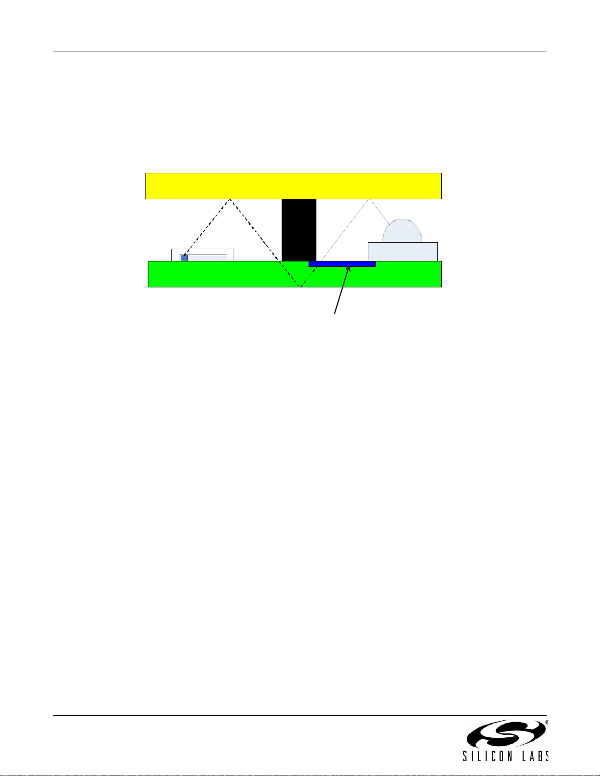
2.3.3.4. Colored Overlays
Clear overlays with screen-printed ink are generally superior to colored overlay materials.
Most companies focus effort in offering different colored materials based on appearance factors to the human eye.
Many of the color materials have not been characterized for their IR transmittance.
With sample “color chips”, it is generally possible to estimate the IR transmittance. There is, however, an important
consideration. Most “color chip” samples come in specific thicknesses. The optical properties are a function of the
thickness.
In general, the opacity and the thickness of materials have an exponential relationship. For example, if 1 mm of
material has 70% transmittance, then 2 mm of material would have a transmittance of (70%)^2= 49%. 3 mm will
lead to (70%)
Although it is convenient to lump together “transmittance” in a single number, actual transmittance vs. spectral
curve is far from linear. In a colored overlay, the transmittance in the IR region is typically higher than that of the
visible region.
Given the exponential relationship of transmittance vs. thickness, the end spectral response looks quit e different
even on the same material. This is due to the exponential nature of transmittance vs. thickness. In Figure 9, the
same material is shown to have a much higher variation with varying thickness while the transmittance in the IR
region appears almost the same. Table 1 illustrates how the numbers are affected by an exponential relationship.
3
= 34.3% transmittance.
®
:
Table 1. Transmittance vs Thickness Illustration
Unit Thickness
Transmittance
10% 1% (10% x 10%)
99% 98% (99% x 99%)
10 Rev. 0.6
2 x Unit Thickness
Transmittance
AN498
Figure 10. Transmittance vs. Thickness Spectral Graph
Coefficients calculated for a given colored overlay thickness may not apply for the same material of a different
thickness. It is strongly advised that lux calculation coefficients be characterized only when a co lored o verlay o f the
proper thickness is available.
The other consequence is that high relative transmittance between the visible and IR portions of the spectrum can
result in high ALS variability. If ALS variation is an important system consideration, it may be advantageous to
choose an overlay with a lower infrared transmittance so that the infrared transmittance more closely matches that
of the visible light transmittance. Doing so will allow lower ALS variation across different light sources. Choosing an
overlay with a significant spectral difference in visible and IR generally leads to higher ALS variance once the
overlay thickness tolerance has been considered.
Acrylic colored overlay samples:
www.eplastics.com/Plastic/
Samples;jsessionid=hv2TMsxLG1JTL9x1TGf2wJhk1TqJ6mRJgsLDXFkXyxD34yxG56nwThb5lT4LxbT9fvQbyW2
8gLGGBvQTFgznztlprMWT51fWTQyhDVQtJZKhJ8wybm8phTntW7TJSwlw!328655193
Makrolon color chip samples (requires registration)
https://www.competenceincolor.com/ChipRequest?channel_id=27
Lexan color chip samples (requires registration)
https://www.sabic-ip.com/cxp/ColorXPress
Rev. 0.6 11
AN498
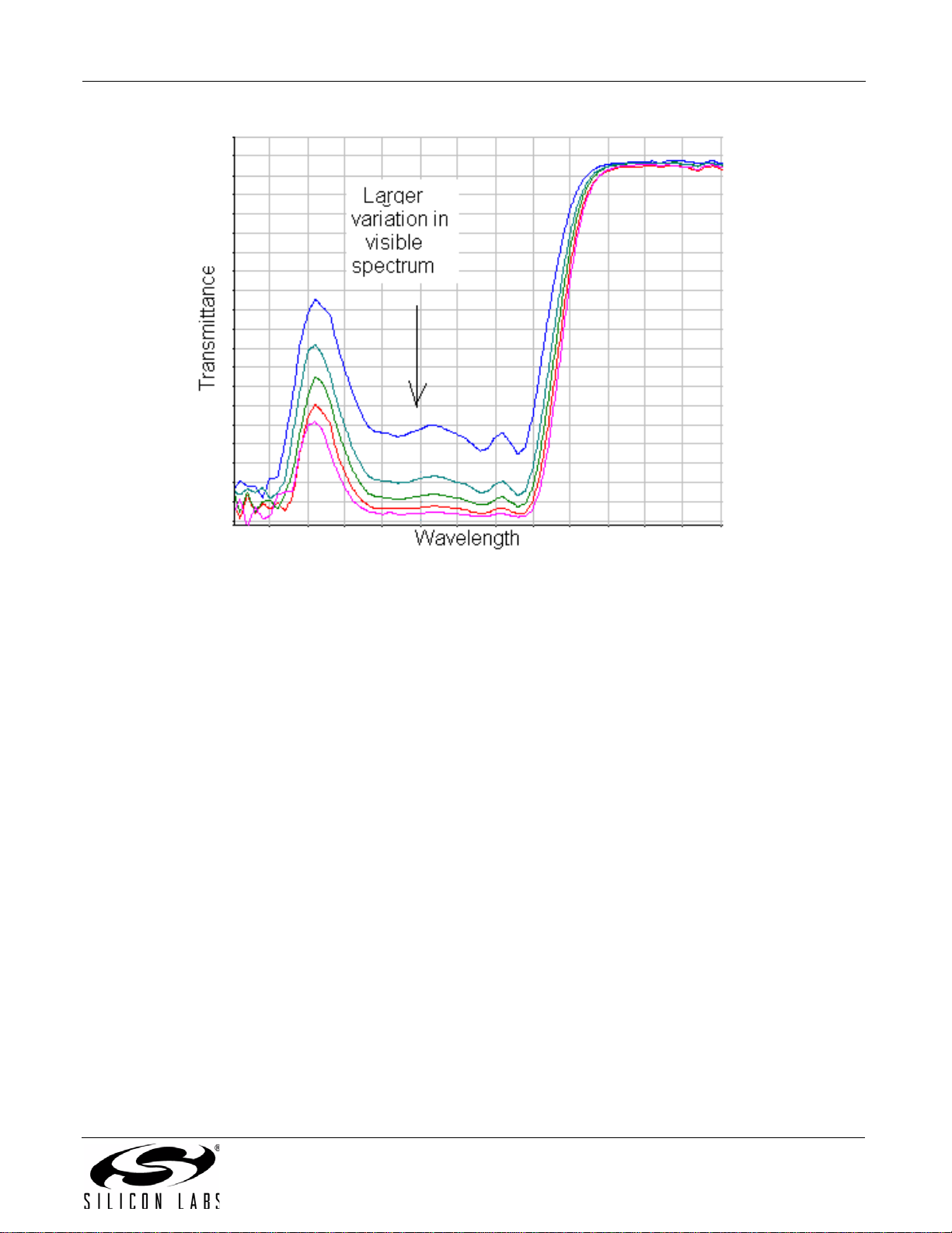
0.66
0.14
0.415
0.16
0.12
0.65
Large IR photodiode
Small IR photodiode
and visible photodiode
(stacked)
Pin 1
0.115 die
offset to
package
Ape rture
Field of V iew
An gle of V iew
Light Sourc e
Si114x
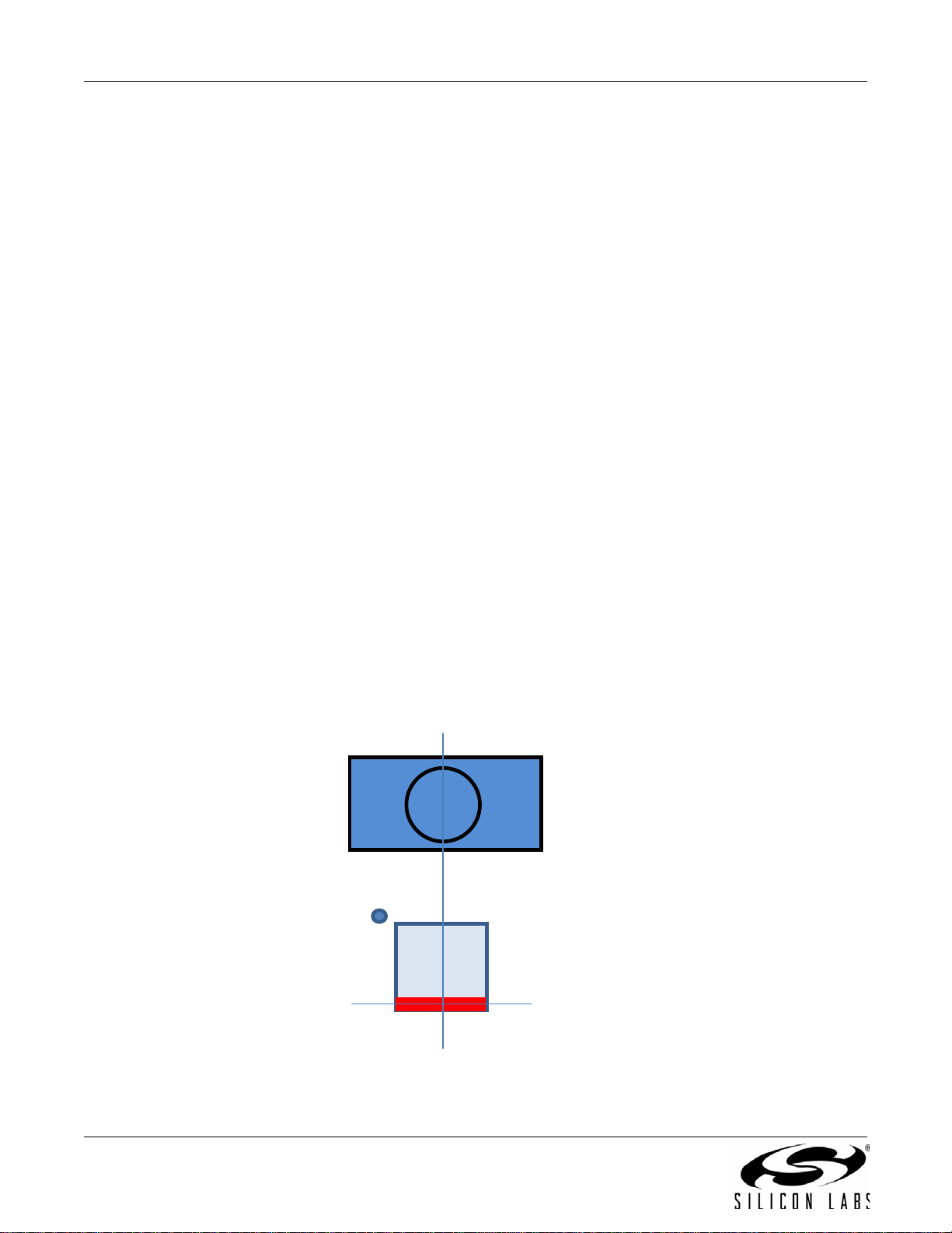
2.4. Photodiode Locations, Apertures, and View Angles
The photodiodes locations are shown in Figure 11. It is generally accepted that these photodiodes are treated as a
single strip for layout and mechanical design considerations.
Figure 11. Si114x Photodiode Centers
An aperture is an opening through which light enters. The aperture is transparent or translucent and is surrounded
by an opaque material. The distance from the aperture and the size of the aperture define the Si114x field of view.
When a light source is within the field of view, the angle formed relative to the photodiode normal vector is called
the “Angle of View”.
Figure 12. Aperture, Field of View and View Angle
12 Rev. 0.6
AN498
The radiant power that falls on the photodiode is a function of the angle of view. The number of ADC codes
reported by the Si114x is influenced by the angle of view through a cosine relationship. All things being equal, a
light source at a larger view angle results in a lower ADC count.
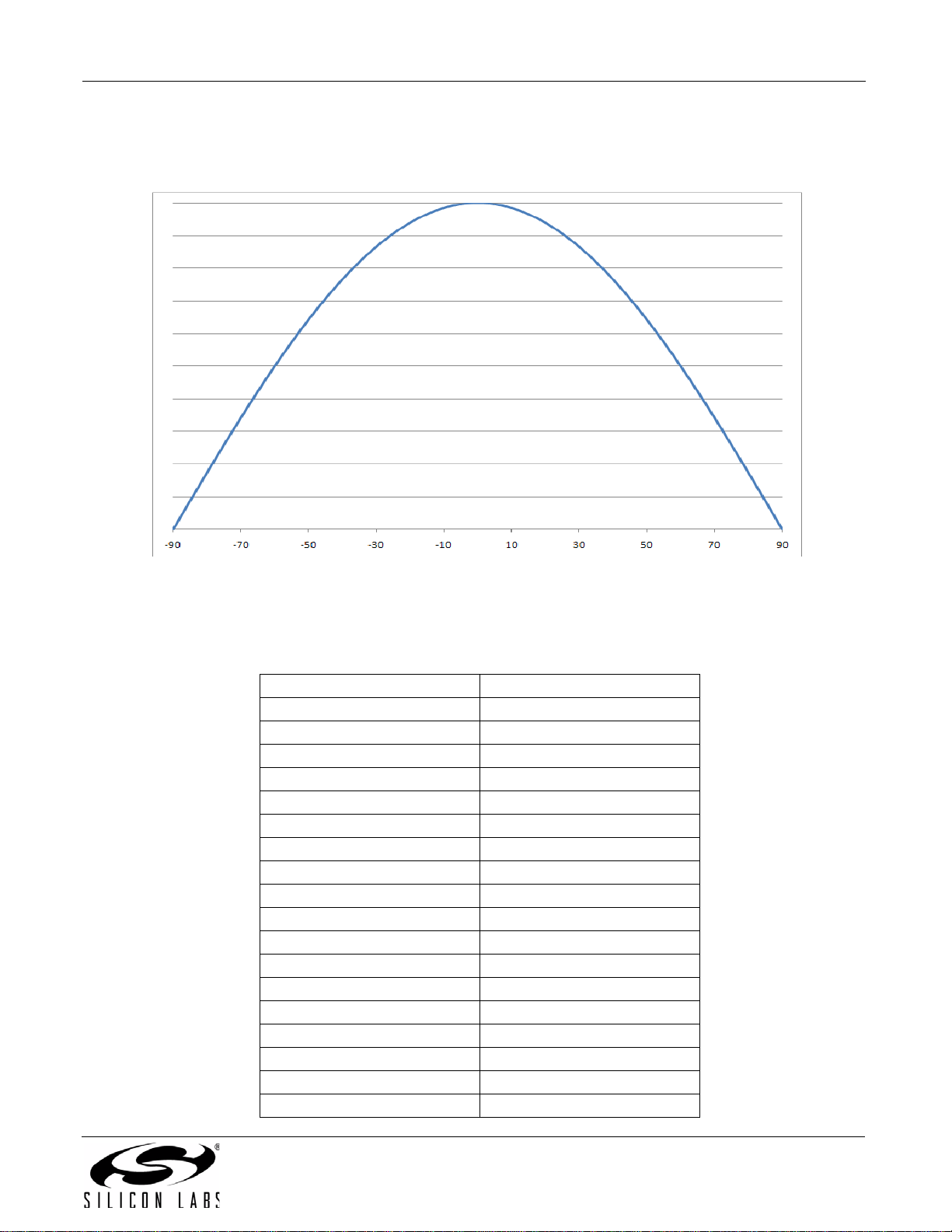
Figure 13. ADC Reading of Equidistant Point Light Source vs. Angle of View
When the light source is an infinite distributed surface, the relationship of th e field of view versus the tot al a vailable
reading is shown on Table 2.
Table 2. Relative ADC Reading vs. Field of View (Large Surface Light Source)
Field of View ADC Codes
180 100%
170 100%
160 98%
150 97%
140 94%
130 91%
120 87%
110 82%
100 77%
90 71%
80 64%
70 57%
60 50%
50 42%
40 34%
30 26%
20 17%
10 9%
Rev. 0.6 13
AN498
photodiodes
irLED
If the target object is small (smaller than the field of view), the ADC codes reported by the Si114 x ar e influenced by
the angle of view. The field of view only needs to be as big as the expected location of the target. An example of
such an application is a 50 cm range where the angle subtended by the target object is small compared to the field
of view.
If the target object is large (larger than the field of view), the amount of light received by the Si114x is influenced by
the field of view. An example application is the cell-phone cheek detector; the cheek represents a large object due
to its location relative to the sensor. For this case, maximizing the field of view is important. For these applications,
a field of view of 120 ° is recommended. This means that, for best performance, the aperture either needs to be
large or near the Si114x. By increasing the aperture, the greatest amount of light can enter the Si114x, and less
light needs to be thrown at the target object, leading to a more efficient design.
2.5. Close Range Application with Single-Port Topology
This section applies only to Single-Port topology when the target is close. For systems that employ optical blocking
or a Dual-Port topology, the optical leakage is controlled through the optical b locking material. In a Single-Port
topology, geometry is the primary method of limiting the optical leakage.
2.5.1. IrLED Choice
The irLED chosen for this must have a half-angle of 22° or less. As described in "2.3. Optical/Mechanical
Components" on page 5, light power that does not exit the system generally ends up fueling optical leakage
through secondary leakage paths. Choosing a low half-angle irLED causes much of the light power to be directed
outside the system, resulting in lower optical leakage.
Another important consideration of the irLED is that it must be as tall as the product’s construction will allow. By
choosing a tall irLED, the irLED will be nearer the overlay. Having the irLED near the overlay causes most of the
light to go outside the system rather than being reflected back in and causing higher levels of optical leakage.
The Si114x Evaluation Platforms use the Osram SFH 4056. Many of these recommendations can also apply to
other irLEDs as long as the radiation pattern is narrower than 22°.
2.5.2. Si1141 Orientation
It is best to orient the Si1141 so that the distance between the irLED and the photodiodes is maximized. Pin 1, Pin
10, and Pin 9 should face the irLED. The worst orientation is facing Pins 4, 5, and 6 towards the irLED. Using this
orientation allows the furthest distance between the irLED and the Si1141 photodiodes leading to the least optical
leakage.
Si1141
14 Rev. 0.6
Figure 14. Si1141 Orientation
AN498
Si1141
Pin 1, Pin 9
Photodiode
PCB
> 0.8 mm
A
B
L
O
C
K
Note Si1141
Orientation
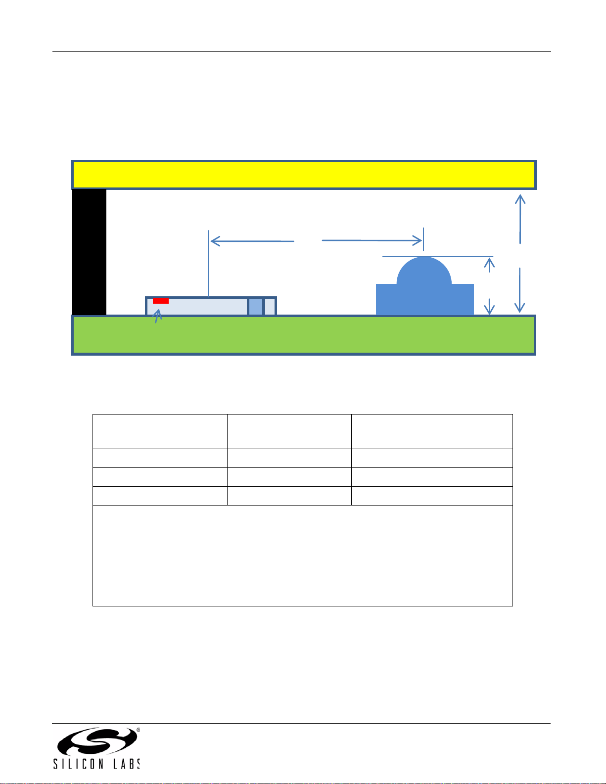
2.5.3. Single-Port Design Dimensions
From the perspective of minimizing optical leakage, the overlay transmittance is not a factor. A high transmittance
overlay is preferred for PS because this generally leads to lower system power as less light ne eds to be directe d to
the target to allow it to be detected. It is generally feasible to compensate for high transmittance by throwing more
light out, but this becomes a power consumption consideration.
Overlay
B
irLED
Figure 15. Si1141 Single Port Reference Drawing
Table 3. Single-Port Dimensions (Cheek Detector Application)
PCB Surface to Overlay
Bottom (A)
< 1 mm 5 mm 20 mm
1 mm to 2 mm 7 mm 20 mm
2mm to 3mm 10mm 20mm
Notes:
1. The Si1141 should be oriented so that pins 4 and p in 6 are fa rthe st away from the ir LED.
2. The irLED height is assumed to be 0.8 mm. When possible, minimize the gap from the
top of the irLED and the bottom of the overlay.
3. No optical isolation between the Si1141 and irLED is assumed.
4. The target object is a cheek (5 cm) or black hair (2.5 cm).
5. The overlay thickness is 0.5 mm.
6. The irLED Power Rating is 1/16 W.
Center-to-Center
Minimum (B)
Center-to-Center Maximum (B)
Rev. 0.6 15
AN498
PCB
photodiode center on overlay form
reflection points. Trace lines to determine
block rays before they
PCB has IR transmittance. Use
Small gap needed for cheek
detection applications
where object is against the
overlay.
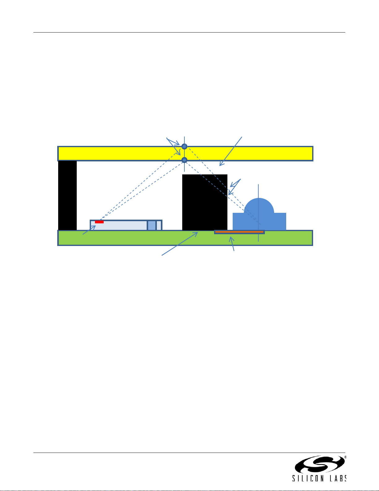
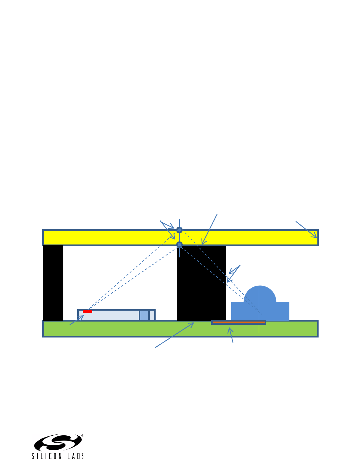
2.5.4. Partial Optical Block
If the dimensions in Table 3 cannot be met, some optical blocking is necessary. For applications where the target
object can be pressed against the overlay (e.g. cheek detection) the optical blocking should be partial only.
Otherwise, there would not be a reading when a cheek is pressed against the overlay.
The key concept in designing an optical block is that the primary reflection path from the irLED to the Si1141 be
traced, and these rays should be blocked.
Midpoint between irLED center and
minimum optical block height and width.
Overlay
get to the overlay
Si1141x
Photodiode
Flush optical block to PCB
Pin 9
irLED
ground fill on to block leakage.
Figure 16. Partial Optical Blocking
16 Rev. 0.6
AN498
PCB
irLED
Midpoint between irLED center and
photodiode center on overlay form
reflection points. Trace lines to determine
minimum optical block height and width.
get to the overlay
PCB has IR transmittance. Use
Tight Seal between the
optical block and the
overlay
Minimize overlay
thickness
2.6. Long Range Applications
If the target is small or far away, the Si1141 may need to operate at a higher ADC sensitivity setting. This is
accomplished through increasing the PS_ADC_GAIN setting. When increasing the PS_ADC_GAIN setting, both
reflectance and optical leakage are magnified. To allow operation at the highest possible ADC sensitivity, the
optical leakage should be kept low so as possible.
The limitation to how high the PS_ADC_GAIN setting can be set is a function of:
Ambient IR
Optical Leak ag e
The IR ambient can be controlled through the following methods:
1. Limiting field of view by using a smaller Aperture (see "2.4. Photodiode Loca tions, Apertu res, and V ie w Angles"
on page 12)
2. Limiting field of view by using Lenses
3. Using special overlays, such as a Visible Light Blocking Overlay (Longpass Filters) when CFL/Fluorescent
lighting is the predominant lighting condition.
In general, the Dual Port topology provides the lowest leakage. The Hybrid approach can be used as long as
proper optical blocking is used.
Si114x
Pin 9
Photodiode
Flush optical block to PCB
Figure 17. Long Range Application using Hybrid Topology (Optical Blocking)
Overlay
block rays before they
ground fill on to block leakage.
Rev. 0.6 17
 Loading...