

Page 1
AIT Drive
User’s Guide
2-546-891-14(1)
AIT-3 Ex TAPE DRIVE
AITi390-ST/AITi390V-ST
AIT-2 Turbo TAPE DRIVE
AITi200-A/AITi200T-A/
AITi200-ST/AITi200T-ST
AIT-1 Turbo TAPE DRIVE
AITi100-A/AITi100T-A/
AITi100-ST/AITi100T-ST
AIT-E Turbo TAPE DRIVE
AITi50-A/AITi50T-A
2004 Sony Corporation
Page 2

WARNING
To reduce the risk of fire or
electric shock, do not expose
this apparatus to rain or
moisture.
To avoid electrical shock, do not
open the cabinet.
Refer servicing to qualified
personnel only.
This document contains proprietary
information which is protected by
copyright.
All rights reserved. No part of this
document may be photocopied,
reproduced or translated to another
language without prior written consent
of Sony.
The information contained in this
document is subject to change without
notice.
SONY MAKES NO WARRANTY
OF ANY KIND WITH REGARD TO
THIS DOCUMENT.
Sony shall not be liable for errors
contained herein, indirect, special,
incidental or consequential damages in
connection with the furnishing,
performance or use of this document.
The following models are assigned the
following model numbers for
regulatory compliance certifications.
Mode: Model No.
AITi200-A: ATDNA3A
AITi100-A and AITi50-A: ATDNA2A
AITi390-ST: SDX-870V
AITi200-ST: SDX-570V
AITi100-ST: SDX-470V
The number is indicated on the model
number label on your drive along with
the rated voltage and current.
VORSICHT
Diese Ausrüstung erfüllt die
Europäischen EMC-Bestimmungen für
die Verwendung in folgender /
folgenden Umgebung(en):
• Wohngegenden
• Gewerbegebiete
•Leichtindustriegebiete
(Diese Ausrüstung erfüllt die
Bestimmungen der Norm EN55022,
Klasse B.)
ATTENTION
According to the EU Directives related
to product safety, EMC and R&TTE
the manufacturer of this product is
Sony Corporation, 1-7-1 Konan
Minato-ku Tokyo, 108-0075 Japan.
The Authorised Representative is Sony
Deutschland GmbH, Hedelfinger
Strasse 61,70327 Stuttgart, Germany.
For any service or guarantee matters
please refer to the addresses given in
separate service or guarantee
documents.
2
Page 3
AUFMERKSAMKEIT
Im Sinne der EU Richtlinien bezüglich
Produktsicherheit, EMV und R&TTE
ist Sony Corporation, 1-7-1 Konan
Minato-ku Tokyo, 108-0075 Japan der
Hersteller dieses Produktes.
Bevollmächtigter ist Sony
Deutschland GmbH, Hedelfinger
Strasse 61, D-70327 Stuttgart. Für
Service oder Garantieangelegenheiten
wenden Sie sich bitte an die in
separaten Service oder
Garantiedokumenten angegebenen
Adressen.
European Union Restriction of
Hazardous Substances Directive
compliant.
Entspricht der Richtlinie der
Europäischen Union zur
Beschränkung der Verwendung
gefährlicher Stoffe.
• Hereby, Sony Corporation,
declares that this SDX-870V is in
compliance with the essential
requirements and other relevant
provisions of Directive 1999/5/
EC.
• Sony-yhtiö vakuuttaa täten että
SDX-870V tyyppinen laite on
direktiivin 1999/5/EY oleellisten
vaatimusten ja sitä koskevien
direktiivin muiden ehtojen
mukainen.
• Hierbij verklaart de onderneming
Sony dat het toestel SDX-870V
in overeenstemming is met de
essentiële eisen en de andere
relevante bepalingen van richtlijn
1999/5/EG
• Bij deze verklaart de
onderneming Sony dat deze
SDX-870V voldoet aan de
essentiële eisen en aan de
overige relevante bepalingen van
Richtlijn 1999/5/EC.
• Par la présente la société Sony
déclare que l’appareil SDX-870V
est conforme aux exigences
essentielles et aux autres
dispositions pertinentes de la
directive 1999/5/CE
• Par la présente, la société Sony
déclare que ce SDX-870V est
conforme aux exigences
essentielles et aux autres
dispositions de la directive 1999/
5/CE qui lui sont applicables
• Härmed intygar företaget Sony
att denna SDX-870V står I
överensstämmelse med de
väsentliga egenskapskrav och
övriga relevanta bestämmelser
som framgår av direktiv 1999/5/
EG.
• Undertegnede Sony samarbejde
erklærer herved, at følgende
udstyr SDX-870V overholder de
væsentlige krav og øvrige
relevante krav i direktiv 1999/5/
EF
• Hiermit erklärt die Firma Sony,
dass sich dieser/diese/dieses
SDX-870V in Übereinstimmung
mit den grundlegenden
Anforderungen und den anderen
relevanten Vorschriften der
Richtlinie 1999/5/EG befindet”.
(BMWi)
3
Page 4

• Hiermit erklärt die Firma Sony
die Übereinstimmung des
Gerätes SDX-870V mit den
grundlegenden Anforderungen
und den anderen relevanten
Festlegungen der Richtlinie
1999/5/EG. (Wien)
• ΜΕ ΤΗΝ ΠΑΡΟΥΣΑ η ΕΤΑΙΡΙΑ
Sony ∆ΗΛΩΝΕΙ ΟΤΙ SDX-870V
ΣΥΜΜΟΡΦΩΝΕΤΑΙ ΠΡΟΣ ΤΙΣ
ΟΥΣΙΩ∆ΕΙΣ ΑΠΑΙΤΗΣΕΙΣ ΚΑΙ
ΤΙΣ ΛΟΙΠΕΣ ΣΧΕΤΙΚΕΣ
∆ΙΑΤΑΞΕΙΣ ΤΗΣ Ο∆ΗΓΙΑΣ
1999/5/ΕΚ
• Con la presente la società Sony
dichiara che questo SDX-870V è
conforme ai requisiti essenziali
ed alle altre disposizioni
pertinenti stabilite dalla direttiva
1999/5/CE.
• Por medio de la presente la
corporación Sony declara que el
SDX-870V cumple con los
requisitos esenciales y
cualesquiera otras disposiciones
aplicables o exigibles de la
Directiva 1999/5/CE
•O Fabricante Sony declara que
este SDX-870V está conforme
com os requisitos essenciais e
outras disposições da Directiva
1999/5/CE.
• Prin prezenta, corporaţia Sony
declară că acest SDX-870V
respectă cerinţele esenţiale și
este în conformitate cu
prevederile Directivei 1995/5/EC.
4
Page 5

IMPORTANT SAFEGUARDS
For your protection, please read these
safety instructions completely before
operating the appliance, and keep this
manual for future reference.
Carefully observe all warnings,
precautions and instructions on the
appliance, or the one described in the
operating instructions and adhere to
them.
USE
Power Sources – This unit should be
operated only from the type of power
source indicated on the marking label.
If you are not sure of the type of
electrical power, consult your dealer or
local power company.
For the unit with a three-wire
grounding type ac plug:
If you are unable to insert the plug into
the outlet, contact your electrician to
have a suitable plug installed. Do not
defeat the safety purpose of the
grounding plug.
AC Power cord: (for AC mains
operating unit only)
The AC power cord should have
appropriate safety approvals or
marking for the country in which the
equipment will be used. Consult your
dealer or local power company.
Cleaning – Unplug the unit from the
wall outlet before cleaning or
polishing it. Do not use liquid
cleaners or aerosol cleaners.
Use a cloth lightly dampened with
water for cleaning the exterior of the
unit.
Object and Liquid Entry – Never
push objects of any kind into the unit
through openings as they may touch
dangerous voltage points or short out
parts that could result in a fire or
electric shock. Never spill liquid of
any kind on the unit.
5
Page 6

INSTALLATION
Water and Moisture – Do not use
power-line operated units near water for example, near a bathtub,
washbowl, kitchen sink, or laundry
tub, in a wet basement, or near a
swimming pool, etc.
Power-Cord Protection – Route the
power cord so that it is not likely to be
walked on or pinched by items placed
upon or against them, paying
particular attention to the plugs,
receptacles, and the point where the
cord exits from the appliance.
Accessories – Do not place the unit on
an unstable cart, stand, tripod, bracket,
or table. The unit may fall, causing
serious injury to a child or an adult,
and serious damage to the unit. Use
only a cart stand tripod, bracket, or
table recommended by the
manufacturer.
Ventilation – The slots and openings
in the cabinet are provided for
necessary ventilation. To ensure
reliable operation of the unit, and to
protect it from overheating, these slots
and openings must never be blocked or
covered.
• Never cover the slots and openings
with a cloth or other materials.
• Never block the slots and openings
by placing the unit on a bed, sofa,
rug or other similar surface.
• Never place the unit in a confined
space, such as a bookcase, or builtin cabinet, unless proper ventilation
is provided.
SERVICE
Damage Requiring Service – Unplug
the unit from the wall outlet and refer
servicing to qualified service
personnel under the following
conditions:
• When the power cord or plug is
damaged or frayed.
• If liquid has been spilled or objects
have fallen into the unit.
• If the unit has been exposed to rain
or water.
• If the unit has been subject to
excessive shock by being dropped,
or the cabinet has been damaged.
• If the unit does not operate normally
when following the operating
instructions. Adjust only those
controls that are specified in the
operating instructions. Improper
adjustment of other controls may
result in damage and will often
require extensive work by a
qualified technician to restore the
unit to normal operation.
• When the unit exhibits a distinct
change in performance - this
indicates a need for service.
Servicing – Do not attempt to service
the unit yourself as opening or
removing covers may expose you to
dangerous voltage or other hazards.
Refer to all servicing to qualified
service personnel.
6
Page 7

Contents
AITi200-A/AITi100-A/AITi50-A/AITi390-ST/AITi200-ST/AITi100-ST
Tape Drive ........................................................................................................... 8
Introduction .............................................................................................................. 9
Product Features ............................................................................................... 9
Precautions ..................................................................................................... 11
Installation .............................................................................................................. 12
Jumper Setting................................................................................................12
Connectors......................................................................................................13
Option Switches (DIP Switch) .......................................................................14
Mounting Holes.............................................................................................. 16
Reconfiguring from 5.25" Model to 3.5" Model............................................20
Orientation......................................................................................................21
Attaching and Removing the Dust Cover ............................................................... 22
Attaching the Dust Cover ............................................................................... 22
Removing the Dust Cover ..............................................................................24
Operation ................................................................................................................ 25
Location of 3 LEDs ........................................................................................25
Drive Operation..............................................................................................26
Interface Implementation........................................................................................29
Supported ATA Commands ...........................................................................29
Supported ATAPI Packet Commands............................................................29
Specifications ......................................................................................................... 30
Product Specifications....................................................................................30
Sony Contacts .........................................................................................................32
7
Page 8

AITi200-A/AITi100-A/AITi50-A/ AITi390-ST/AITi200-ST/AITi100-ST Tape Drive
The Sony AITi200-A/AITi100-A/AITi50-A/AITi390-ST/AITi200-ST/
AITi100-ST drive is a high capacity data storage device using Advanced
Intelligent tape (AIT) technology. The AITi200-A/AITi100-A/AITi50-A/
AITi390-ST/AITi200-ST/AITi100-ST drive achieves high data reliability
through Read-After-Write, an additional level of Error Correction Code,
and other features.
The Sony AITi200-A/AITi100-A/AITi50-A/AITi390-ST/AITi200-ST/
AITi100-ST drive stores data on tape using a standard format called AIT
(Advanced Intelligent Tape) and ALDC formats.
8
Page 9
Introduction
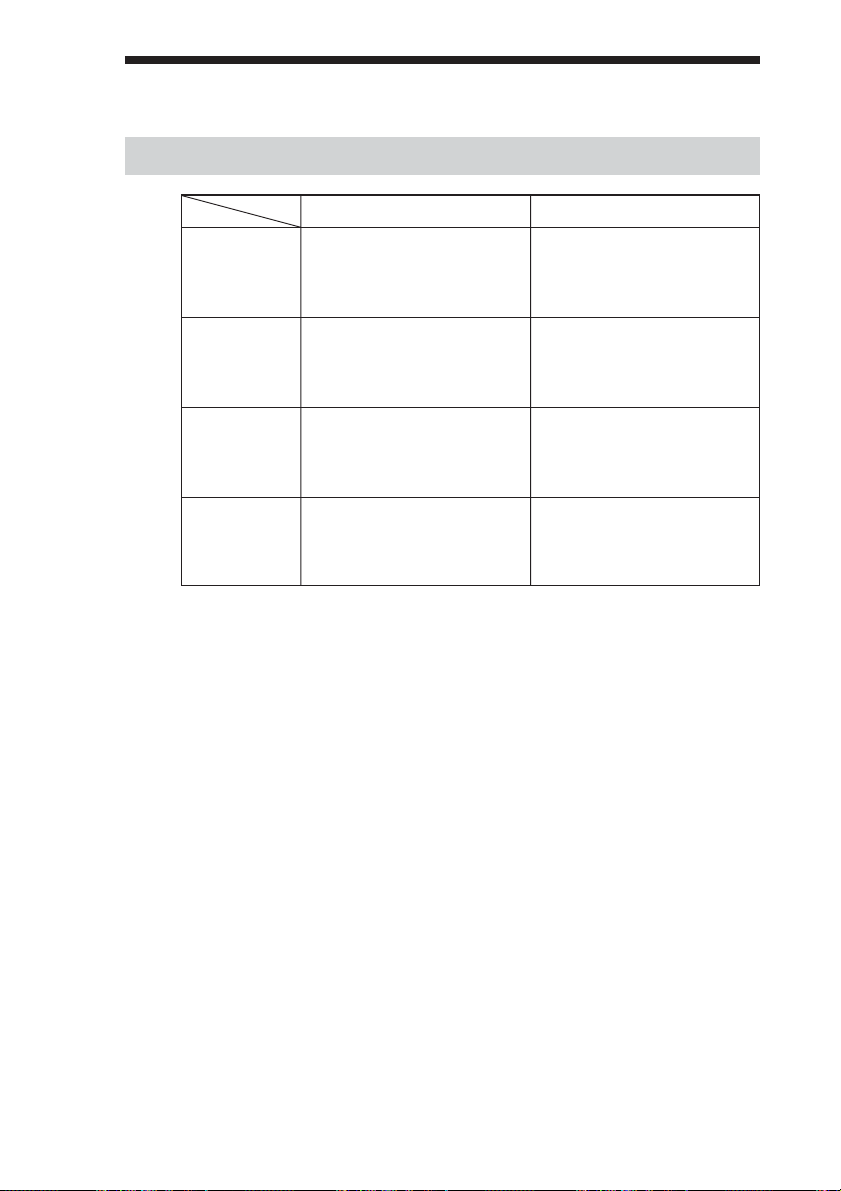
Product Features
Data Capacity Transfer Rate (sustained)
AITi390-ST
AITi200-A
AITi200-ST
AITi100-A
AITi100-ST
AITi50-A
* Assuming a 2.6 : 1 compression ratio.
(The compression ratio varies according to the type of data.)
150 GB uncompressed
(with AIT-3 Ex 246 m tape)
390 GB compressed*
(with AIT-3 Ex 246 m tape)
80 GB uncompressed
(with AIT-2 Turbo 186 m tape)
208 GB compressed*
(with AIT-2 Turbo 186 m tape)
40 GB uncompressed
(with AIT-1 Turbo 186 m tape)
104 GB compressed*
(with AIT-1 Turbo 186 m tape)
20 GB uncompressed
(with AIT-E Turbo 98 m tape)
52 GB compressed*
(with AIT-E Turbo 98 m tape)
18 MB/s uncompressed
(with AIT-3 Ex tape)
12 MB/s uncompressed
(with AIT-2 Turbo tape)
6 MB/s uncompressed
(with AIT-1 Turbo tape)
6 MB/s uncompressed
(with AIT-E Turbo tape)
AITi200-A/AITi100-A/AITi50-A
• Supported Format
AITi200-A: AIT-E Turbo, AIT-1, AIT-1 Turbo, AIT-2, and AIT-2 Turbo
AITi100-A: AIT-E Turbo, AIT-1, and AIT-1 Turbo
AITi50-A: AIT-E Turbo
• Burst Transfer Rate 100 MB/s Ultra DMA (mode 5)
• Large 12 MB Buffer Memory
• 3.5" Standard Height, 5.25" Half Height
• ATA/ATAPI-6 Interface
• Frame Rewrite Function
• Three levels of Error Correction Code (ECC)
• High Speed search (120 times normal Read/Write speed)
• Random Read, Append Write
9
Page 10

AITi390-ST/AITi200-ST/AITi100-ST
• Supported Format
AITi390-ST: AIT-2 Turbo, AIT-3, and AIT-3 Ex (read/write)
AIT-E Turbo, AIT-1, AIT-1 Turbo, and AIT-2 (read only)
AITi200-ST: AIT-E Turbo, AIT-1, AIT-1 Turbo, AIT-2, and
AIT-2 Turbo
AITi100-ST: AIT-E Turbo, AIT-1, and AIT-1 Turbo
• Burst Transfer Rate 150 MB/s
• SATA 1.5 Gbps (Gen.1)
• Large Buffer Memory
AITi390-ST: 64 MB
AITi200-ST: 24 MB
AITi100-ST: 12 MB
• 3.5" Standard Height, 5.25" Half Height
• Frame Rewrite Function
• Three levels of Error Correction Code (ECC)
• High Speed search (120 times normal Read/Write speed)
• Random Read, Append Write
10
Page 11

Precautions
Installation
Avoid placing the drive in a location subject to:
– high humidity
– high temperature
– mechanical shock and vibration
– direct sunlight
Operation
• Do not move the drive while it is operating. It may cause malfunction.
• Avoid exposing the drive to sudden changes from a low to high in
temperature. This may cause water condensation to collect inside the
drive. If the ambient temperature should suddenly rise while the drive is
turned on , wait at least one hour before turning on the drive. If you
attempt to operate the drive immediately after a sudden increase in
temperature, a malfunction may occur.
• Turning off the power to the drive while it is writing to tape may cause
the tape to become unreadable. All previously negotiated parameters will
be lost, whenever power to the drive is cycled.
Transportation
• Keep the original packing materials to facilitate transportation of the
drive.
• Always remove the tape before moving the drive. After removing the
drive from the computer, repack the drive into its original packing.
Backup Application
Make sure to use a backup application that is confirmed to operate with an
ISV.
11
Page 12

Installation
Jumper Setting
The following figures apply to the AITi100-A and AITi50-A.
IDE Interface Connector
Master
Slave
Cable Select
No Connection
12
Jumpers Drive Setting
Master
Slave
Cable Select
Power Connector
4 3 2 1
5V GND GND 12V
Page 13

Connectors
The following figures apply to the AITi200-ST.
SATA Power
Connector (*1)
Caution
DO NOT USE both the SATA Power Connector (*1) and Legacy Power
Connector (*2) at the same time.
Using both connectors possible cause the system damage.
SATA Signal
Connector
Legacy Power
Connector (*2)
4 3 2 1
5V GND GND 12V
13
Page 14

Option Switches (DIP Switch)
DIP Switch Positions
Default
DIP Switch
1 Drive Mode (OFF)
2 Drive Mode (OFF)
3 Drive Mode (OFF)
4 Drive Mode (OFF)
5 Reserved (OFF)
6 Periodic Cleaning Req (OFF)
7 DC Control (1) (ON)
8 DC Control (2) (OFF)
14
Page 15

Cleaning Request Mode
Periodic cleaning requests can be enabled by a DIP switch.
1 Drive Mode
ON
OFF
12345678
2 Drive Mode
3 Drive Mode
4 Drive Mode
5 Reserved
6 Periodic Cleaning Req (ON)
7 DC Control (1)
8 DC Control (2)
When switch 6 is ON, cleaning requests are enabled. When enabled, the
“CLEANING REQUEST” LED on the front panel lights after every 100
hours of operation.
When this LED lights, clean the drive with a head cleaning cartridge.
Note
To maintain the drive in optimum condition in environments affected by dust and other
contaminants, we recommend keeping cleaning requests enabled.
Data Compression Control DIP switch
Data compression can be selected by DIP switches. Data compression is
enabled while position 7 [DC Control (1)] is ON. Control by host can be
disabled when position 8 [DC Control (2)] is ON.
15
Page 16

Mounting Holes
The following figures apply to the AITi100-A and AITi50-A.
For 3.5" Standard Height
_
+
4.8 0.5mm
_
+
[0.19" 0.02"]
_
+
41.2 0.5mm
_
+
[1.62" 0.02"]
6-M3 (depth 2.5mm [0.10"] max.)
6-M3 (depth 2.5mm [0.10"] max.)
_
+
_
+
_
+
_
+
90.0 0.3mm [3.54" 0.01"]
60.0 0.3mm
[2.36" 0.01"]
_
+
_
+
21.0 0.3mm
[0.83" 0.01"]
_
+
_
+
7.4 0.6mm [0.29" 0.02"]
_
+
_
+
9.8 0.6 mm
[0.39" 0.02"]
7.6±0.5 mm (0.30±0.02 in)
_
+
_
+
155.0 0.5mm [6.10" 0.02"]
95.5 mm (3.76 in)
_
+
94.0 0.5mm [3.70" 0.02"]
_
+
101.6 0.5mm [4.00" 0.02"]
_
+
_
+
_
+
_
+
42.0 0.3mm
[1.65" 0.01"]
70.0 0.3mm [2.76" 0.01"]
_
+
_
+
_
+
_
+
31.0 0.3mm
[1.22" 0.01"]
16
Page 17

For 5.25" Half Height
6-M3
7.0mm
[0.28"]
_
+
_
+
79.2 0.3mm [3.12" 0.01"]
_
+
47.5 0.3mm
_
+
9.9 0.5mm
_
[0.39" 0.02"]
+
_
+
21.8 0.5mm
_
+
[0.86" 0.02"]
_
+
41.2 0.5mm
_
+
[1.62" 0.02"]
7.6±0.5 mm
(0.3±0.02 in)
_
+
_
+
_
+
_
+
_
+
79.2 0.3mm [3.12" 0.01"]
_
+
[1.87" 0.01"]
_
+
_
+
_
+
155.0 0.5mm [6.10" 0.02"]
42.0 0.3mm
[1.65" 0.01"]
70.0 0.3mm [2.76" 0.01"]
_
+
_
+
_
+
_
+
9.8 0.6 mm
[0.39" 0.02"]
_
+
7.4 0.6mm [0.29" 0.02"]
_
+
31.0 0.3mm [1.22" 0.01"]
146±0.5 mm
(5.75±0.02 in)
95.5 mm
(3.76 in)
_
+
94.0 0.5mm [3.70" 0.02"]
_
+
139.6 0.5mm [5.50" 0.02"]
_
+
146.0 0.5mm [5.75" 0.02"]
_
+
149.0 0.5mm [5.87" 0.02"]
_
+
_
+
_
+
_
+
4-M3
_
+
_
+
79.2 0.3mm [3.12" 0.01"]
_
+
_
+
47.5 0.3mm
[1.87" 0.01"]
17
Page 18

The following figures apply to the AITi200-ST.
For 3.5" Standard Height
_
+
4.8 0.5mm
_
+
[0.19" 0.02"]
_
+
41.2 0.5mm
_
+
[1.62" 0.02"]
6-M3 (depth 2.5mm [0.10"] max.)
6-M3 (depth 2.5mm [0.10"] max.)
_
+
_
+
_
+
_
+
90.0 0.3mm [3.54" 0.01"]
60.0 0.3mm
[2.36" 0.01"]
_
+
_
+
21.0 0.3mm
[0.83" 0.01"]
_
+
_
+
7.4 0.6mm [0.29" 0.02"]
_
+
_
+
9.8 0.6 mm
[0.39" 0.02"]
8.3±0.5 mm (0.33±0.02 in)
_
+
_
+
155.0 0.5mm [6.10" 0.02"]
96.1 mm (3.78 in)
_
+
94.0 0.5mm [3.70" 0.02"]
_
+
101.6 0.5mm [4.00" 0.02"]
_
+
_
+
_
+
_
+
42.0 0.3mm
[1.65" 0.01"]
70.0 0.3mm [2.76" 0.01"]
_
+
_
+
_
+
_
+
31.0 0.3mm
[1.22" 0.01"]
18
Page 19

For 5.25" Half Height
8.3±0.5 mm
(0.33±0.02 in)
146±0.5 mm
(5.75±0.02 in)
96.1 mm
(3.78 in)
7.0mm
[0.28"]
_
+
_
+
79.2 0.3mm [3.12" 0.01"]
_
+
9.9 0.5mm
_
[0.39" 0.02"]
+
_
+
21.8 0.5mm
_
+
[0.86" 0.02"]
_
+
41.2 0.5mm
_
+
[1.62" 0.02"]
6-M3
_
+
_
+
_
+
_
+
_
+
79.2 0.3mm [3.12" 0.01"]
_
+
_
+
47.5 0.3mm
[1.87" 0.01"]
_
+
_
+
_
+
155.0 0.5mm [6.10" 0.02"]
42.0 0.3mm
[1.65" 0.01"]
70.0 0.3mm [2.76" 0.01"]
_
+
_
+
_
+
_
+
9.8 0.6 mm
[0.39" 0.02"]
_
+
7.4 0.6mm [0.29" 0.02"]
_
+
31.0 0.3mm [1.22" 0.01"]
_
+
94.0 0.5mm [3.70" 0.02"]
_
+
139.6 0.5mm [5.50" 0.02"]
_
+
146.0 0.5mm [5.75" 0.02"]
_
+
149.0 0.5mm [5.87" 0.02"]
_
+
_
+
_
+
_
+
4-M3
_
+
_
+
79.2 0.3mm [3.12" 0.01"]
_
+
_
+
47.5 0.3mm
[1.87" 0.01"]
19
Page 20

Reconfiguring from 5.25" Model to 3.5" Model
You can reconfigure the 5.25" model to the 3.5" model yourself.
1 Remove the 2 screws for each side rail.
2 Take the side rail off.
Side Rail (L)
Side Rail (R)
20
Page 21

Orientation
10°10
10°10
°
10
°
10
°
°
10
°
10
°
21
Page 22

Attaching and Removing the Dust Cover
Attaching the Dust Cover
1 Align the dust cover’s hinge clips (one on each side) with the
pins of the drive bezel.
• The dust cover should be positioned so that the magnets* on the
cover’s back face the drive bezel.
*
This magnet does not affect the tape of the cartridge.
• Holding the dust cover at an angle as shown in the figure below, set
the hinge clips on top of the bezel pins, positioning them so that
they bracket the pins.
22
Page 23

2 Press down at an angle on each side in turn until you hear
the hinge clips click into place.
Caution
Do not press the dust cover in horizontally from the front. Doing so
could cause the dust cover to break.
3 Close the dust cover.
This completes attachment of the dust cover.
23
Page 24

Removing the Dust Cover
1 Open the dust cover.
2 Holding the dust cover at both corners, carefully raise the
dust cover.
The dust cover hinge clips and drive bezel pins uncouple.
24
Note
We recommend that you use the drive with the dust cover.
Page 25

Operation
Location of 3 LEDs
There are three LED indications (TAPE MOTION LED, CLEANING
REQUEST LED, REPLACE TAPE LED) and an EJECT button on the
front panel of the unit.
Front Panel (for 3.5" Standard Height)
Advanced
Intelligent
Tape
LED
TAPE
MOTION
CLEANING
REQUEST
REPLACE
TAPE
EJECT button
LED Indication for Drive Status
The LED indicators are defined as follows.
LED
TAPE CLEANING REPLACE
MOTION REQUEST TAPE
Independent Independent Tape Loaded
Independent Independent
Tape Access in Progress (write/read)
Independent Independent Tape Access in Progress (others)
Independent Independent Cleaning is requested
Independent Independent Cleaning is Not Completed
Independent Independent Media Error Occurred
H/W Error Occurred
on
Slow
1 pulse (0.9 sec on/0.3 sec off)
Fast
1 pulse (0.3 sec on/0.3 sec off)
Sense
25
Page 26

Drive Operation
Loading a Cartridge
Note
While setting the data cartridge, do not turn off the host computer. This
may cause a malfunction or damage data.
1 Turn on the host computer. Check that the drive’s TAPE
MOTION LED, CLEANING REQUEST LED and REPLACE
TAPE LED go off.
2 Open the dust cover.
3 Set the AIT data cartridge orientation as shown here and
insert it into the data cartridge slot.
By inserting the data cartridge to the extent, it is automatically set in
the drive and the TAPE MOTION LED lights.
Unloading a Cartridge
The cartridge can be removed from the AITi200-A, AITi100-A, and
AITi50-A either in response to a ATAPI Unload Command, or by pressing
the EJECT bottom.
By pressing EJECT button, the tape is rewound and the cartridge ejected
from the slot.
26
Page 27

Write-protecting a Cartridge
Cartridges can be write-protected by sliding the tab on the back of the
cartridge. In this state, data can be read from the tape but not written onto it.
AIT-E Turbo
AIT-1
Using your fingernail, push the switch in the direction of the arrow to
protect the tape from writing or accidental erasure.
Return the switch to its original position to re-enable writing.
AIT-1 Turbo
AIT-2 Turbo
AIT-2
AIT-3
AIT-3 Ex
Using a Cleaning Cartridge
To keep the AIT drive in top condition, clean the head as needed using a
head cleaning cartridge with the AIT logo. When the head needs cleaning,
the CLEANING REQUEST indicator lights.
Use the cleaning cartridge made exclusively for each model.
Cleaning cartridge to use
AITi390-ST SDX3X-CL
AITi200-A, AITi200-ST, AITi100-A, SDX1-CL
AITi100-ST, AITi50-A
How to Clean
1 Load the head cleaning cartridge into the AIT drive. Cleaning
starts automatically.
2 After about 15 seconds, cleaning will stop and the cartridge
will be ejected automatically.
Caution
Do not rewind the cleaning cartridge and reuse it. When you reach the end of
the cartridge, dispose it and buy a new cleaning cartridge with the AIT logo.
27
Page 28

Storage Precautions
• Keep cartridges in their cases when not in the drives.
• Avoid storing cartridges in dusty locations, in direct sunlight, near heaters
or air conditioners, or in humid locations.
• Do not place cartridges on dashboards or in car storage trays.
28
Page 29

Interface Implementation
Supported ATA Commands
– ATAPI SOFT RESET (0x08)
– EXECUTE DRIVE DIAGNOSTIC (0x90)
– ATAPI PACKET COMMAND (0xA0)
– ATAPI IDENTIFY DEVICE (0xA1)
– STANDBY IMMEDIATE (0xE0)
– IDLE IMMEDIATE (0xE1)
– CHECK POWER MODE (0xE5)
– SLEEP (0xE6)
– SET FEATURE (0xEF)
Supported ATAPI Packet Commands
Mandatory ATAPI command set:
Supporting most of all SCSI commands in AITi200-A/AITi100-A/AITi50-A.
– ERASE
– INQUIRY
– LOAD/UNLOAD
– LOCATE
– LOG SELECT
– LOG SENSE
– MODE SELECT
– MODE SENSE
– READ
– READ POSITION
– REQUEST SENSE
– REWIND
– SPACE
– TEST UNIT READY
– WRITE
– WRITE BUFFER
– WRITE FILEMARK
29
Page 30

Specifications
Product Specifications
Dimensions
3.5" 5.25"
Height 41.2 mm (1.62 in) 41.2 mm (1.62 in)
Width 101.6 mm (4.0 in) 146.0 mm (5.75 in)
Depth 155.0 mm (6.1 in) 155.0 mm (6.1 in)
Mass
AITi390-ST AITi200-A/AITi200-ST AITi100-A/AITi50-A/AITi100-ST
3.5" 780 g (27.5 oz.) 780 g (27.5 oz.) 740 g (26.1 oz.)
5.25" 1010 g (35.6 oz.) 1050 g (37.0 oz.) 970 g (34.2 oz.)
Temperature and Humidity Range
Temperature
Operating
Non-Operating (mech.) – 40 ˚C to 70 ˚C (∆T<20 ˚C/h)
Non-Operating (tape) – 40 ˚C to 45 ˚C (∆T<20 ˚C/h)
Humidity
Operating 20 to 80% RH, non-condensing
Non-Operating (mech.) 5 to 95% RH (∆RH<30%/h)
Non-Operating (tape) 20 to 80% RH (∆RH<30%/h)
5 ˚C to 40 ˚C (∆T<10 ˚C/h) (41 ˚F to 104 ˚F (∆T<18 ˚F/h))
(– 40 ˚F to 158 ˚F (∆T<36 ˚F/h))
(– 40 ˚F to 113 ˚F (∆T<36 ˚F/h))
Maximum wet bulb temperature : 26 ˚C (78.8 ˚F/h)
Maximum wet bulb temperature : 45 ˚C (113 ˚F/h)
Power Requirements
AITi390-ST
Voltage Max Ripple
5 V +/– 5 % 100 mVp-p 1.4 A 2.0 A
12 V +/– 10 % 150 mVp-p 0.75 A 2.0 A
AITi200-A
Voltage Max Ripple
5 V +/– 5 % 100 mVp-p 1.4 A 1.7 A
12 V +/– 10 % 150 mVp-p 0.5 A 1.2 A
Typical Maximum
Typical Maximum
Current
Current
30
Page 31

AITi200-ST
Voltage Max Ripple
5 V +/– 5 % 100 mVp-p 1.4 A 1.7 A
12 V +/– 10 % 150 mVp-p 0.5 A 1.3 A
AITi100-A/AITi50-A
Voltage Max Ripple
5 V +/– 5 % 100 mVp-p 0.9 A 1.2 A
12 V +/– 10 % 150 mVp-p 0.3 A 1.2 A
AITi100-ST
Voltage Max Ripple
5 V +/– 5 % 100 mVp-p 1.0 A 1.4 A
12 V +/– 10 % 150 mVp-p 0.3 A 1.4 A
Typical Maximum
Typical Maximum
Typical Maximum
Current
Current
Current
Air-cooling Requirement
Surrounding temperature < 40 ˚C (104 ˚F)
Clean air flow is recommended to minimize the possibility of data loss.
31
Page 32

Sony Contacts
For further information, please contact:
Sony Electronics Inc., Tape Storage Solutions (USA)
URL: http://www.storagebysony.com
Sony of Canada Ltd., AV/IT Marketing Group
Computer Peripherals Product Marketing
115 Gordon Baker Road Toronto, Ontario, M2H 3R6 Canada
TEL: (416) 499-1414 or (1) 800-961-7669
FAX: (416) 499-8541
Sony Business Europe
URL: http://www.sonyisstorage.com/
Electronics Devices Marketing (Singapore)
(A division company of Sony Electronics (S) Pte. Ltd.)
Enterprise Storage Solutions Dept.
2 International Business Park, #01-10 Tower One, The Strategy,
Singapore 609930
TEL: 65-6544-8000 FAX: 65-6544-7390
Sony Corporation of Hong Kong Ltd.
Computer Peripheral Sales & Marketing Division
Electronic Devices Marketing Hong Kong
45/F, The Lee Gardens, 33 Hysan Avenue, Causeway Bay, Hong Kong
TEL: (852) 2909-1008 FAX: (852) 2909-2001
Sony Corporation of Hong Kong Ltd. Beijing Rep. Office
Computer Peripheral Div.
Full Link Plaza Tower A 11/F., No.18 Chaoyangmenwai Ave., Beijing
100020 P.R.C.
TEL: 86-10-6588-0633 FAX: 86-10-6588-0855
URL: http://www.sony.com.cn/ed/cp/ait/
Sony Corporation of Hong Kong Ltd.,
Electronic Devices Marketing Hong Kong
Computer Peripherals Sales & Marketing Div.
8/F, One Corporate Avenue, 222 Hu Bin Road. Luwan District,
Shanghai. P.R.C. Postcode 200021
TEL: 86-21-6121-6878
URL: http://www.sony.com.cn/ed/cp/ait/
32
Page 33

Sony Brasil Ltda.
Rua Inocéncio Tobias, 125-BlocoA, CEP01144-000, São Paulo-SP-Brasil
TEL: (55) 11-3824-6586 to 6598 FAX: (55) 11-3611-9064
URL: http://www.sonybrasil.com
Sony Australia Limited
33-39 Talavera Rd.
NORTH RYDE, NSW 2113
TEL: 1300-13-7669 FAX: 02-9870-5864
e-mail: CIC-customerissues@ap.sony.com
Sony New Zealand
Akoranga Business Park
NORTH SHORE, AUCKLAND
TEL: 0800-76-6969 FAX: 09-308-9300
e-mail: CIC-customerissues@ap.sony.com
Sony Chile Ltda
Av. Kennedy 8017, Las Condes, Santiago, Chile
TEL: (02) 210-6000 FAX: (02) 210-5417
Sony Taiwan Limited
Optical Devices Storage Dept. Data Storage Section
5F, 145 Changchun Road, Taipei 104, Taiwan
TEL: 886-2-2522-7920 FAX: 886-2-2522-2153
Sony Korea Corporation EDMK CP Sales & Marketing Team
34F, ASEM Tower, World Trade Center, 159-1, Samsung-Dong,
Kangnam-Ku, Seoul, 135-798, Korea
TEL: 82-2-6001-4249 FAX: 82-2-6001-4115
URL: http://www.sony.co.kr/cp/
Sony Gulf FZE Computer Display & Peripheral Div.
P.O.BOX 16871, Jebel Ali, Dubai, U.A.E.
TEL: 971-4-8815488 or 8816912 FAX: 971-4-8817210 or 8816259
Sony Marketing of Japan
Business Solution Dept. Server Solution Marketing Section
URL: http://www.sony.co.jp/STORAGE
33
Page 34

 Loading...