

Page 1

AIT Drive
Operating Instructions
4-671-474-12(1)
AIT-3 TAPE DRIVE
AITe260
AIT-2 TAPE DRIVE
AITe130
AIT-1 TAPE DRIVE
AITe90
©2002 Sony Corporation
Page 2

Safety Regulations
Owner’s Record
The model and serial numbers are located on the bottom. Record the serial
number in the space provided below.
Refer to them whenever you call upon your dealer regarding this product.
Model No. Serial No.
________________________ __________________________________
Information
WARNING
To prevent fire or shock hazard, do not expose the
unit to rain or moisture.
To avoid electrical shock, do not open the cabinet.
Refer servicing to qualified personnel only.
Model No. for Regulatory Compliance
Your AIT DRIVE is assigned a Model No. : SDX-D400C, SDX-D500C,
SDX-D700C for regulatory compliance certifications. The number is
indicated on the model number label on your drive along with the rated
voltage and current.
For the customers in the USA
You are cautioned that any changes or modifications not expressly approved
in this manual could void your authority to operate this equipment.
WARNING
Note: This equipment has been tested and found to comply with the limits
for a Class B digital device, pursuant to Part 15 of the FCC Rules. These
limits are designed to provide reasonable protection against harmful
interference in a residential installation. This equipment generates, uses and
can radiate radio frequency energy and, if not installed and used in
accordance with the instructions, may cause harmful interference to radio
communications. However, there is no guarantee that interference will not
occur in a particular installation. If this equipment does cause harmful
interference to radio or television reception, which can be determined by
turning the equipment off and on, the user is encouraged to try to correct the
interference by one or more of the following measures:
• Reorient or relocate the receiving antenna.
• Increase the separation between the equipment and receiver.
• Connect the equipment into an outlet on a circuit different from that to
which the receiver is connected.
• Consult the dealer or an experienced radio/TV technician for help.
This device requires shielded interface cables to comply with FCC emission
limits.
2 Safety Regulations
Page 3
CAUTION
The mains plug on this equipment must be used to disconnect mains power.
Please ensure that the socket outlet is installed near the equipment and shall
be easily accessible.
ACHTUNG
Zur Trennung vom Netz ist der Netzseker aus der Steckdose zu ziehen,
welche sich in der Nähe des Gerätes befinden muß und leicht zugärlich sein
soll.
Hinweis: Der höchste Schalldruckpegel beträgt 70 db (A) oder weniger
gemäß ISO 7779
NOTICE
Use the power cord set approved by the appropriate testing organization for
the specific countries where this unit is to be used.
HINWEIS
Ausserhalb den USA und Kanada das Netzkabel verweden, das von der
dafür anerkannten testorganisation oder zuständigen Behörde des Landes, in
das Gerät betrieben wird, zugelassen ist.
If you have any questions about this product, please refer to Sony contact in
the instruction manual.
DECLARATION OF CONFORMITY
Trade Name: SONY
Model: AITe260/AITe130/AITe90
Responsible Party: Sony Electronics Inc.
Address: 680 Kinderkamack Road, Oradell NJ
07649 USA
Telephone number: 201-930-6972
This device complies with part 15 of the FCC Rules. Operation is subject to
the following two conditions:
(1) This device may not cause harmful interference.
(2) This device must accept any interference received, including
interference that may cause undesired operation.
Diese Ausrüstung erfüllt die Europäischen EMC-Bestimmungen für die
Verwendung in folgender/folgenden Umgebung(en):
– Wohngegenden
– Gewerbegebiete
– Leichtindustriegebiete
(Diese Ausrüstung erfüllt die Bestimmungen der Norm EN 55022,
Klasse B.)
Safety Regulations 3
Page 4

Table of Contents
How to Use this Guide ...................................................................... 5
Part 1.
Introduction
Part 2.
Preparation
Part 3.
Operation
Part 4.
Care and
Maintenance
About AIT Drives ............................................................................... 6
Features.................................................................................................... 6
Useable Cartridges................................................................................... 7
System Components ................................................................................ 7
Part Names and Functions............................................................... 8
Front Panel (AITe130/AITe90)................................................................ 8
Front Panel (AITe260) ............................................................................. 9
Rear Panel..............................................................................................10
Supplied Items................................................................................. 11
Interconnections ............................................................................. 11
SCSI ID Setting ................................................................................ 12
Option Switches (DIP Switch) ........................................................ 12
How to use the AIT Drive................................................................ 14
Cartridge Removal................................................................................. 15
Taking Care of the Drive ................................................................. 16
Safety Considerations ............................................................................16
Avoiding Damage ..................................................................................16
Taking Care of Cartridges .............................................................. 18
Use Precautions .....................................................................................18
Storage Precautions ...............................................................................18
Head Cleaning ................................................................................. 19
How to Clean .........................................................................................19
Appendix
4 Table of Contents
Specifications (AITe260)................................................................. 20
Specifications (AITe130)................................................................. 21
Specifications (AITe90)................................................................... 22
Page 5

How to Use this Guide
This Guide describes the AIT Drive Unit AITe260/AITe130/AITe90, and
how to take care of it. Please read it carefully before using the unit, and keep
it handy for future reference.
The Guide consists of four parts, plus the specifications. Refer to the parts
that relate to your use of the drive.
Part 1 describes the features of the drive, its system components, and the
name and function of each part.
Part 2 describes the necessary connections between the drive and the host
computer. If other SCSI devices are being used, you may need to change the
SCSI ID setting. Read this part if you are installing the drive.
Part 3 describes how to use the drive, including how to turn it on, and how
to insert and remove cartridges. Read this part if you are going to operate the
drive.
Part 4 describes how to take care of the drive and cartridges, and how to
clean the drive heads. Read this part before using the drive.
The Specifications Appendix provides the major specifications of the
AITe260/AITe130/AITe90.
How to Use this Guide 5
Page 6

Part 1. Introduction
About AIT Drives
The AITe260 is an external AIT drive unit that uses data cartridges
conforming to the AIT-3 format. The AITe130 is an external AIT drive unit
that uses data cartridges conforming to the AIT-2 format. The AITe90 is an
external AIT drive unit that uses data cartridges conforming to the AIT-1
format. The AITe260 supports AIT-1, AIT-2, and AIT-3 formats. The
AITe130 supports AIT-1 and AIT-2 formats. The AITe90 supports only
AIT-1 format.
Features
The AIT Drive Unit AITe260 has the following features:
• The Advanced Intelligent Tape format provides a huge data storage capacity
on AIT-1/AIT-2/AIT-3 data cartridges.
• Read After Write Function and third-level error code guarantee high data
reliability.
• Data compression provides 260 gigabytes of storage on 230 m tape-length
cartridge.
The native capacity is 100 gigabytes of storage on 230 m tape-length
cartridge.
• Stored data are automatically checked for compression.
• Ultra 160 SCSI LVD/SE interface is fully supported for host computer
access.
• Read/Write operation is available with AIT-1, AIT-2, and AIT-3 formats.
*1
6 Part 1. Introduction
The AIT Drive Unit AITe130 has the following features:
• The Advanced Intelligent Tape format provides a huge data storage capacity
on AIT-1/AIT-2 data cartridges.
• Read After Write Function and third-level error correction code guarantee
high data reliability.
• Data compression provides 130 gigabytes of storage on 230 m tape-length
cartridge.
The native capacity is 50 gigabytes of storage on 230 m tape-length
cartridge.
• Stored data are automatically checked for compression.
• Ultra Wide LVD/SE SCSI interface is fully supported for host computer
access.
• Read/Write operation is available with AIT-1 and AIT-2 formats.
*1
This is assuming 2.6 : 1 compression ratio.
The degree of data compression attained while recording data varies according to system
environment and data type.
*1
Page 7
Useable Cartridges
The AIT Drive Unit AITe90 has the following features:
• The Advanced Intelligent Tape format provides a huge data storage capacity
on AIT-1 data cartridges.
• Read After Write Function and third-level error correction code guarantee
high data reliability.
• Data compression provides 91 gigabytes of storage on 230 m tape-length
cartridge.
*1
The native capacity is 35 gigabytes of storage on 230 m tape-length
cartridge.
• Stored data are automatically checked for compression.
• Ultra Wide LVD/SE SCSI interface is fully supported for host computer
access.
• Read/Write operation is available with AIT-1 format.
*1
This is assuming 2.6 : 1 compression ratio.
The degree of data compression attained while recording data varies according to system
environment and data type.
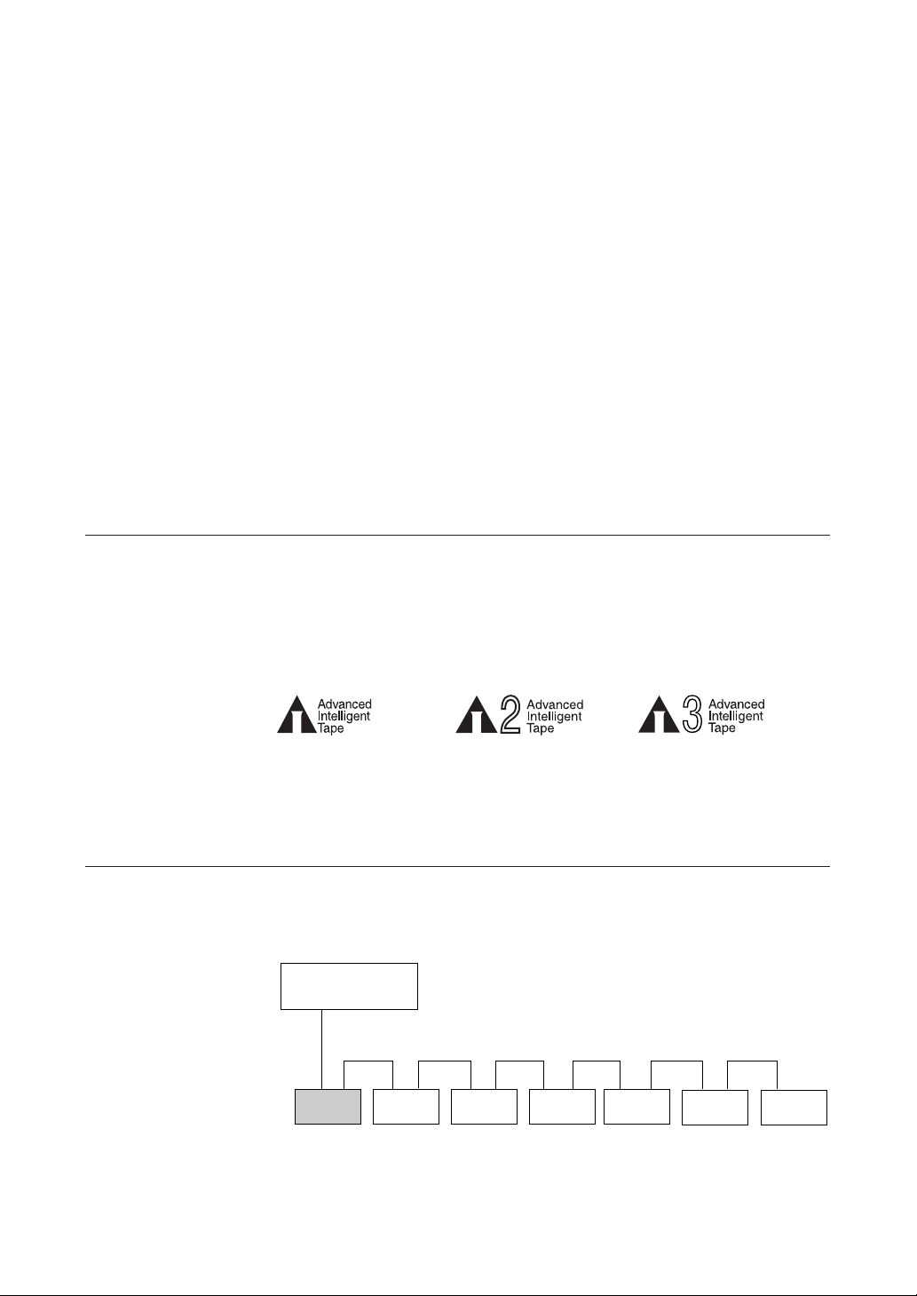
Data cartridges used with the AITe90 must be marked with the AIT-1, logo.
The AITe130 can be used with data cartridges marked with AIT-1 or AIT-2
logo. The AITe260 can be used with data cartridges marked with the AIT-1,
AIT-2, or AIT-3 logo.
Caution
Be sure to use only the cartridges designed specifically for AIT (do not use
8 mm cartridges for video).
System Components
The AITe260/AITe130/AITe90 connects to the host computer via on Ultra
Wide LVD/SE SCSI interface.
AITe260/AITe130/AITe90
The AITe260 can connects to the host computer via a Ultra 160 SCSI
interface.
AIT-1 LOGO AIT-2 LOGO AIT-3 LOGO
Host Computer
Peripheral Devices
Figure 1-1. Example of System Components
Part 1. Introduction 7
Page 8
Part Names and Functions
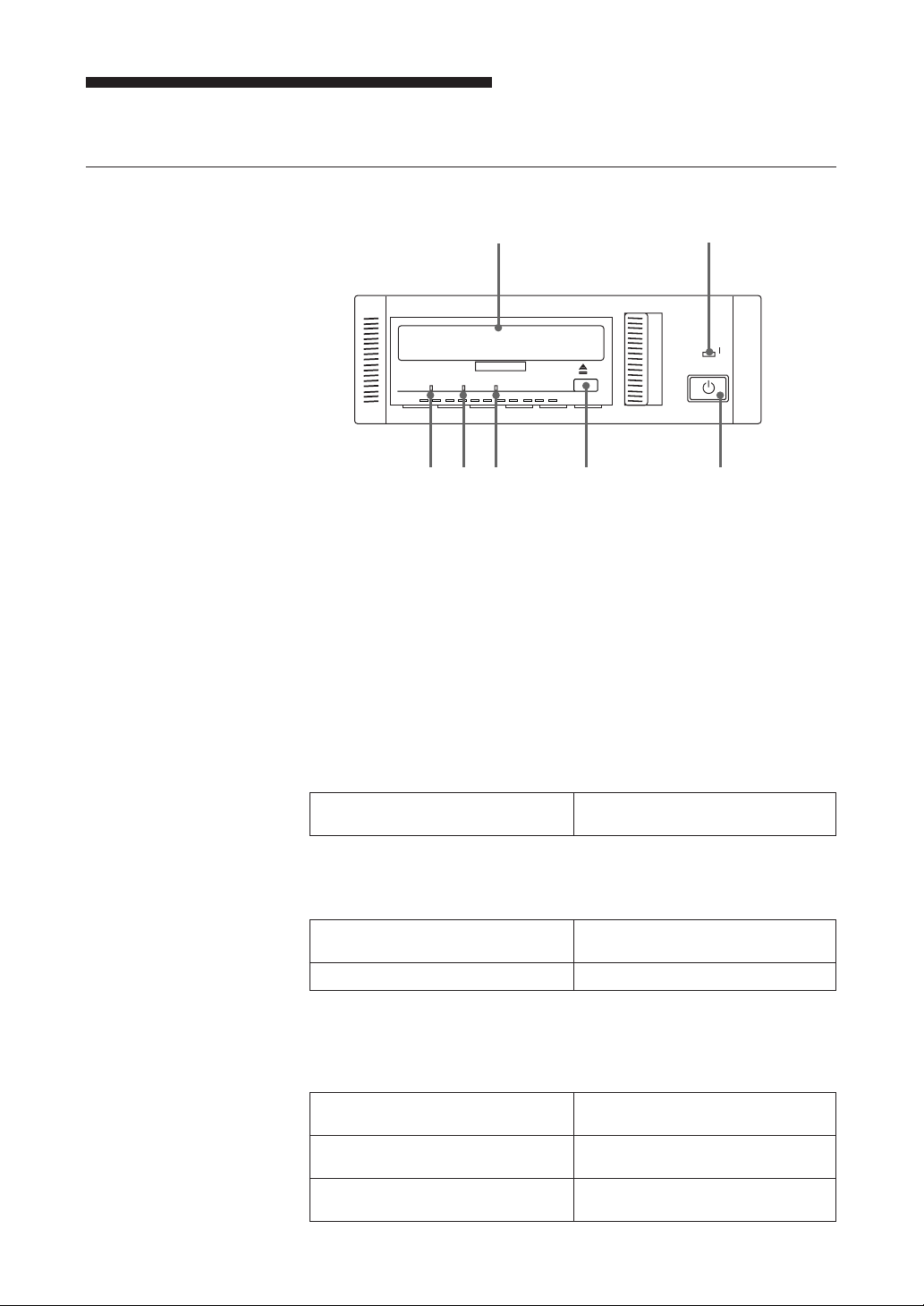
Front Panel (AITe130/AITe90)
12
BUSY TAPE STATUS
POWER
76543
Figure 1-2. Front panel
1 AIT Data Cartridge Receptacle
See page 14 for information on inserting and removing a AIT data
cartridge.
2 POWER Indicator
Lights while the drive is on.
3 BUSY Indicator
Lights when data is being transferred through the SCSI interface. This
indicator also lights under the following conditions:
Drive is reading or writing normally: repeated blinking (same on-off
interval).
4 TAPE Indicator
When a AIT cartridge is installed, this indicator lights. This also lights
under the following conditions:
Inserting and removing a cartridge: repeated blinking (same on-off
Cartridge deteriorated: alternating long-short blinking.
interval).
8 Part 1. Introduction
5 STATUS Indicator
Lights when an inserted cartridge is write-protected. This indicator also
lights under the following conditions:
Drive needs cleaning: repeating long-on, short-off
blinking.
End of Tape during cleaning: repeating blinking (same on-off
interval).
Drive Malfunctioning: repeating short-on (once or twice),
long-off blinking.
Page 9

6 EJECT Button
7 POWER Switch
Front Panel (AITe260)
Refer to AITe130/AITe90 front panel for unmarked parts.
Push to remove a data cartridge from the drive.
Press to turn the drive on or off.
1
Figure 1-3. Front panel
1 LED
The LED indicate the status of the AITe260 as follows.
TAPE MOTION
On - - Tape loaded
Slow flash - - Read/Write in
(0.9 sec on/0.3 sec off)
Fast flash - - Other tape access
(0.3 sec on/0.3 sec off)
-On -
-
- - On Media error
Fast flash Fast flash Fast flash
(0.3 sec on/0.3 sec off) (0.3 sec on/0.3 sec off) (0.3 sec on/0.3 sec off)
CLEANING REQUEST
Slow flash
(0.9 sec on/0.3 sec off)
REPLACE TAPE Meaning
progress
in progress
Cleaning
necessary
-
Cleaning not
complete
Hardware error
Part 1. Introduction 9
Page 10

Rear Panel
1
243
Figure 1-4. Rear Panel
1 Rotary Selector Switch
SCSI ID selector.
2 AC IN Connector
Connect the supplied power cable here.
3 SCSI Connector
Connects to the SCSI bus connector of the host computer or another
SCSI peripheral.
10 Part 1. Introduction
4 Cooling Fan
Page 11

Part 2. Preparation
After you confirm that you have all of the required accessories for your
installation, connect the drive to the host computer, and select the SCSI ID
with the rotary switch on the rear panel.
Supplied Items
When you first open the box, make sure it contains the following items.
Contact your supplier if anything is missing or broken.
• AIT Drive Unit
• Power Cable
• Operator’s Guide
Interconnections
The SCSI bus allows connection of up to fifteen peripherals to the host
computer. Use a SCSI cable with a half pitch 68 pin connector.
Precautions
• Switch off the host computer and peripherals before connecting the SCSI
cable.
• Make sure the SCSI connectors are pressed tightly together.
• If this unit is the last (or only) device on the SCSI bus, make sure to connect
a SCSI bus terminator to the open connector.
• The total length of the SCSI cable(s) between the host computer and the last
device should be less than 12 meters.
AC power
Figure 2-1 Interconnections
*1
It should be less than 1.5 meters, if connected to single-ended SCSI host adaptor.
*1
Part 2. Preparation 11
Page 12

SCSI ID Setting
The SCSI ID is set by the rotary switch on the rear panel. Press the + or buttons to move the number up or down, respectively.
As shipped from the factory, the SCSI ID is set to 0. Press the switch buttons,
if necessary, to select the SCSI ID number you require.
Precautions
• The SCSI ID must be different from IDs of the other peripherals on the
SCSI bus.
• As shipped from the factory, Term power is ON. A SCSI bus terminator
must be connected to the SCSI bus before use.
• Before changing the SCSI ID setting, be sure to turn off the power with the
POWER switch on the front panel.
Option Switches (DIP Switch)
Remove the two slotted screws by using a slotted screwdriver. Remove the
access cover to change the DIP switch settings. (Refer to the following
figure for details changing the DIP switch settings.)
After changing the DIP switch settings, replace access cover and tighten the
two slotted screws using a slotted screwdriver.
CAUTION
Before removing the access cover to change DIP switch settings on the
drive, turn off the computer and disconnect the power cord from the unit.
Once the DIP switch settings have been changed, replace the access cover
using the two original slotted screws provided.
Access Cover
Slotted
Screws
DIP Switch
Figure 2-2. DIP Switch Access
12 Part 2. Preparation
Page 13

DIP Switch Positions
1 Reserved (OFF)
2 Reserved (OFF)
3 Reserved (OFF)
4 Reserved (OFF)
5 Terminator Power (ON)
6 Reserved (OFF)
7 DC Control (1) (ON)
Figure 2-3. DIP Switch Settings
8 DC Control (2) (OFF)
Data Compression Control DIP Switch
Data compression can be selected by DIP switches. Data compression is
enabled while position 7 [DC Control (1)] is ON. Control by host can be
disabled when position 8 [DC Control (2)] is ON.
Part 2. Preparation 13
Page 14

Part 3. Operation
This section describes how to use the AIT drive, and how to handle data
cartridges.
How to use the AIT Drive
1 Press the POWER switch on the front panel.
The POWER indicator should light, and the STATUS, BUSY and TAPE
indicators (with the AITe260, the TAPE MOTION, CLEANING
REQUEST, and REPLACE TAPE indicators) should blink as the selftest is performed.
2 When the three indicators stop blinking, you can insert a data cartridge as
shown below. The TAPE indicator will blink, and if the cartridge is
write-protected, the STATUS indicator will light. (With the AITe260,
even if the cartridge is write-protected, only the TAPE MOTION
indicator lights.)
14 Part 3. Operation
Figure 3-1. Inserting a data cartridge
3 Computer software controls the reading and writing of tapes. While
reading or writing, the BUSY indicator blinks. (With the AITe260, the
TAPE MOTION indicator blinks.)
Page 15

Cartridge Removal
Press the EJECT button.
The cartridge ejects automatically.
Figure 3-2. Press the EJECT button
Caution
Do not push the EJECT button while the BUSY indicator is blinking (with
the AITe260, when the TAPE MOTION indicator is blinking) : to do so may
destroy data on the tape.
Part 3. Operation 15
Page 16

Part 4. Care and Maintenance
Taking Care of the Drive
Safety Considerations
■ Power
• Be sure to use only 100-240 V AC.
• Avoid plugging into the same outlet as high-current equipment like copiers
or shredders.
■ Power Cable Precautions
• Do not crush the cable or place heavy items on it. If the cable insulation
appears worn or broken, do not use the cable.
• Always unplug the cable by holding the plug: never pull the cable itself, as
it will break.
• If the drive is not being used for a long time, unplug the cable from the
outlet.
Avoiding Damage
■ Avoid shock and vibration
Intense shock, such as from dropping the drive, will damage it.
■ Environmental considerations
Do not store or use the drive in locations subject to:
• high humidity • excessive dust
• high temperature • intense vibration
• direct sunlight • sudden changes in temperature
■ Proper ventilation
To avoid overheating, install the drive where it will have free air circulation
around the case, and do not cover it during operation. The drive can
malfunction if the internal temperature rises too high.
■ Avoid sudden changes in temperature
If the drive is moved from a cool place to a warm place, or if the room
temperature suddenly rises, moisture may condense inside the case. After a
sudden change in temperature, wait at least one hour before turning the drive
on. If the drive is turned on with condensation inside, and a cartridge is
installed, the drive or the tape can be damaged.
16 Part 4. Care and Maintenance
Page 17

■ Abnormal occurrences
If the drive behaves abnormally, or if it begins to smell or smoke,
immediately unplug it from the wall outlet and contact your supplier for
assistance.
■ Cabinet cleaning
Wipe the cabinet with a soft dry cloth. For heavy dirt, wipe with a soft cloth
moistened with a gentle liquid soap, then wipe again with a soft dry cloth. Do
not use alcohol, paint thinner, bug sprays or other volatile solvents, as they
can damage the finish.
Part 4. Care and Maintenance 17
Page 18

Taking Care of Cartridges
Use Precautions
• Avoid heavy vibration and dropping.
• The shutter on the face of the cartridge is opened automatically when it is
inserted into the drive. Do not open the shutter by hand, as touching the tape
may damage it.
• The cartridge was carefully aligned during assembly at the factory. Please
do not try to open it or take it apart.
• The write-protect switch on the face of the cartridge prevents the tape from
being written to or accidentally erased. If you do not need to write to the
tape, move this switch to the write-protect position (in the direction of the
arrow).
• In case of a sudden change in temperature, condensation may interfere with
• Avoid unnecessary insertion and removal of cartridges if you do not need to
• When finished using the drive, remove the cartridge.
Storage Precautions
• Keep cartridges in their cases when not in the drive.
• Avoid storing cartridges in dusty places, in direct sunlight, near heaters or
• Do not place cartridges on the dashboard or in a storage tray in a car.
AIT-1 AIT-2, 3
Using your fingernail, push the switch in the
direction of the arrow to protect the tape
from writing or accidental erasure.
Return the switch to its original position to
re-enable writing.
Figure 4-1. Write-protect switch
reading and writing to a tape.
write or read a tape.
air conditioners, or in humid locations.
18 Part 4. Care and Maintenance
Page 19

Head Cleaning
To keep the AIT drive in top condition, clean the head as needed, using the
proper head cleaning cartridge (sold separately). When the head needs
cleaning, the STATUS indicator will blink.
With the AITe260, the CLEANING REQUEST indicator will blink.
How to Clean
1 Load the head cleaning cartridge (SDX1-CL) into the AIT drive.
2 After about 15 seconds, cleaning will stop and the cartridge will eject
Notice
Do not rewind the cleaning cartridge and reuse it. When you reach the end of
the cartridge, dispose it and buy a new one.
Cleaning starts automatically.
automatically.
One head cleaning cartridge can be used about 30 times.
Part 4. Care and Maintenance 19
Page 20

Appendix
Specifications (AITe260)
■ Performance
Storage Capacity 260 GB compressed
Bit Error Rate less than 10
Data Transfer Rate 12 MB/s uncompressed
(TAPE) 31.2 MB/s compressed
Burst Data Transfer Rate 12 MB/s maximum, asynchronous
(SCSI) 160 MB/s maximum, synchronous
Initialize Time less than 5 seconds
Load Time less than 24 seconds
Unload Time less than 30 seconds
Rewind Time less than 105 seconds (with 230 m tape)
■ Operating Environment
Operating Temperature: 10 to 35 °C
Non-Operating Temperature: –40 to +70 °C
■ Power Supply & Miscellaneous
(with 230 m AIT-3 tape)
100 GB uncompressed
(with 230 m AIT-3 tape)
-17
Humidity: 30 to 80%
Maximum wet bulb temperature: 26 °C
Humidity: 10 to 90%
*1
*1
(no condensation)
20 Appendix
Power Supply 100 to 240 V AC, 50/60 Hz
1.2 A
Case Dimensions 198 × 64.5 × 246 mm (W × H × D)
(excluding protruding parts)
Weight 2.4 kg
Accessories Power Cable (1)
Operator’s Guide/Device Driver
(CD-ROM) (1)
Data Cartridge (1)
Application soft, TapeCopy (CD-ROM) (1)
Quick Start Guide (1)
Specifications may be subject to change, in the interest of technological
improvement, without notice or obligation.
*1
This is assuming 2.6 : 1 compression ratio.
The degree of data compression attained while recording data varies according to system
environment and data type.
Page 21

Specifications (AITe130)
■ Performance
Storage Capacity 130 GB compressed
Bit Error Rate less than 10
Data Transfer Rate 6 MB/s uncompressed
(TAPE) 15.6 MB/s compressed
Burst Data Transfer Rate 12 MB/s maximum, asynchronous
(SCSI) 40 MB/s maximum, synchronous
Initialize Time less than 5 seconds
Load Time less than 24 seconds
Unload Time less than 30 seconds
Rewind Time less than 105 seconds (with 230 m tape)
■ Operating Environment
Operating Temperature: 10 to 35 °C
Non-Operating Temperature: –40 to +70 °C
■ Power Supply & Miscellaneous
(with 230 m AIT-2 tape)
*1
50 GB uncompressed
(with 230 m AIT-2 tape)
-17
*1
Humidity: 30 to 80%
(no condensation)
Maximum wet bulb temperature: 26 °C
Humidity: 10 to 90%
Power Supply 100 to 240 V AC, 50/60 Hz
1.2 A
Case Dimensions 198 × 64.5 × 246 mm (W × H × D)
(excluding protruding parts)
Weight 2.4 kg
Accessories Power Cable (1)
Operator’s Guide/Device Driver
(CD-ROM) (1)
Data Cartridge (1)
Application soft, TapeCopy (CD-ROM) (1)
Quick Start Guide (1)
Specifications may be subject to change, in the interest of technological
improvement, without notice or obligation.
*1
This is assuming 2.6 : 1 compression ratio.
The degree of data compression attained while recording data varies according to system
environment and data type.
Appendix 21
Page 22

Specifications (AITe90)
■ Performance
Storage Capacity 91 GB compressed
Bit Error Rate less than 10
Data Transfer Rate 4 MB/s uncompressed
(TAPE) 10.4 MB/s compressed
Burst Data Transfer Rate 12 MB/s maximum, asynchronous
(SCSI) 40 MB/s maximum, synchronous
Initialize Time less than 5 seconds
Load Time less than 24 seconds
Unload Time less than 30 seconds
Rewind Time less than 105 seconds (with 230 m tape)
■ Operating Environment
Operating Temperature: 10 to 35 °C
Non-Operating Temperature: –40 to +70 °C
■ Power Supply & Miscellaneous
(with 230 m AIT-1 tape)
*1
35 GB uncompressed
(with 230 m AIT-1 tape)
-17
*1
Humidity: 30 to 80%
(no condensation)
Maximum wet bulb temperature: 26 °C
Humidity: 10 to 90%
22 Appendix
Power Supply 100 to 240 V AC, 50/60 Hz
1.2 A
Case Dimensions 198 × 64.5 × 246 mm (W × H × D)
(excluding protruding parts)
Weight 2.4 kg
Accessories Power Cable (1)
Operator’s Guide/Device Driver
(CD-ROM) (1)
Data Cartridge (1)
Application soft, TapeCopy (CD-ROM) (1)
Quick Start Guide (1)
Specifications may be subject to change, in the interest of technological
improvement, without notice or obligation.
*1
This is assuming 2.6 : 1 compression ratio.
The degree of data compression attained while recording data varies according to system
environment and data type.
Page 23

Page 24

 Loading...