

SONY AFR125CX Service Manual
SER VICE MANU AL
AIR CONDITIONER
AF-R50CX
AF-R55CX
AF-R60CX
AF-R50CX
AF-R55CX
AF-R60CX
AF-R70CX
S3205AFR07CX/
MODELS
In the interests of user-safety (Required by safety regulations in some
countries) the set should be restored to its original condition and only
parts identical to those specified should be used.
TABLE OF CONTENTS
SPECIFICATIONS ................................................................................................................................................ 2
EXTERNAL DIMENSIONS ................................................................................................................................... 4
OPERATION INSTRUCTUINS ............................................................................................................................. 5
INSTALLATIOIN INSTRUCTIONS ......................................................................................................................14
DISASSEMBLING PROCEDURE....................................................................................................................... 16
HOW TO REPAIR REFRIGERATION ................................................................................................................ 20
ELECTRICAL COMPONENT TEST .................................................................................................................... 23
MICROCOMPUTER CONTROL SYSTEM ..........................................................................................................24
TROUBLESHOOTING GUIDE ............................................................................................................................28
COOLING LOAD ESTIMATE FORM ...................................................................................................................33
RUNNING CONDITION .......................................................................................................................................35
PACKING AND ACCESSORIES ......................................................................................................................... 37
REPLACEMENT PARTS LIST ............................................................................................................................38
AF-R70CX
Page
SHARP CORPORATION This document has been published to be used for after
sales service only.
The contents are subject to change without notice.
1
AF-R50CX
AF-R55CX
AF-R60CX
AF-R70CX
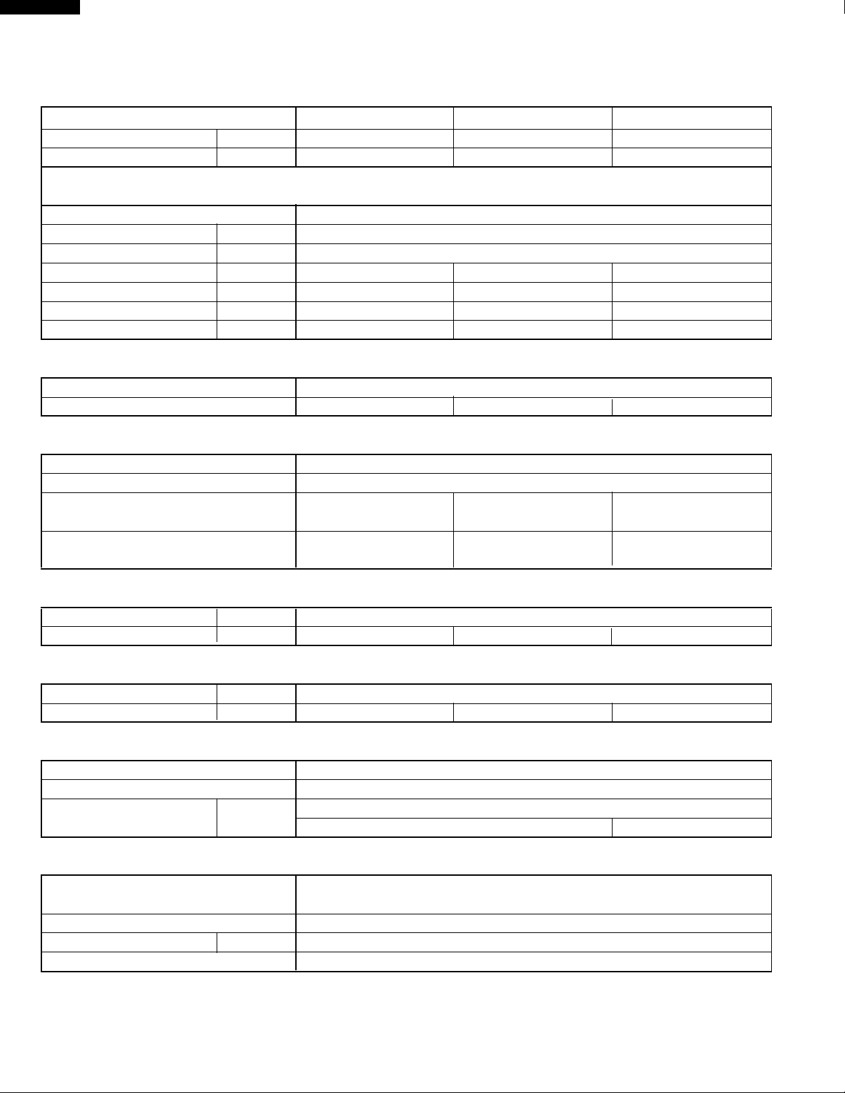
SPECIFICATIONS
Models
AF-R50CX, AF-R55CX
AF-R60CX AF-R70CX
Cooling capacity BTU/h 5000 6000 7000
Moisture removal Pints/h 1.0 1.3 1.8
ELECTRICAL DATA
Phase Single
Rared frequency Hz 60
Rated voltage Volts 115
Rated current Amps 4.6 5.5 6.3
Rated input Watts 500 600 700
Power factor % 95 95 97
EER BTU/Wh 10.0 10.0 10.0
COMPRESSOR
Type (Hermetically sealed rotary type)
Model, Motor output
RM5455GQ86, 400W
39R141AA-04P
, 460W
RM5470GQ86, 550W
REFRIGERANT SYSTEM
Evaporator Louver fin, Grooved tube, 7mm, Hair pin
Condenser Louver fin, Grooved tube, 7mm, Hair pin
Control O.D. x I.D. x Length x Q'ty(mm) 2.7 x 1.1 x 400 x 1 2.7 x 1.2 x 700 x 1 2.7 x 1.3 x 600 x 1
(Capillary tube)
Refrigerant volume R-22(OZ) 8.5 9.2 11.3
(Factory change)
NET DIMENSIONS
Width Height Depth
inches(mm)
17-23/32(450) x 14-9/16(370) x 15-1/4(387)
Net Weight lbs 46 47 50
GROSS DIMENSIONS
Width Height Depth
inches(mm)
20-7/8(530) x 18-1/8(460) x 18-3/8(467)
Gross Weight lbs 51 52 56
FAN SYSTEM
Indoor side(Evaporator) Centrifugal fan
Outdoor side(Condenser) Propeller fan
Air flow rate(indoor side) CFM High / Med / Low
195 / 175 / 150 190 / 170 / 145
OTHERS
Safety devices Compressor: Overload relay
Fan motor: Internal thermal protector
Air filter Polypropylene net
Power cord length ft 6.0
Power plug type 125V, 10A
2
ELECTRICAL PARTS
Models
AF-R50CX, AF-R55CX
AF-R60CX AF-R70CX
Running capacitor 250V-40µF 250V-25µF 250V-40µF
Fan capacitor 250V-6µF
Thermistor 15kΩ at 78˚F
Fan motor OBM-2016K1
(MLA998)
Overload relay MRA99484 B200-130-141E KA-122LAI21
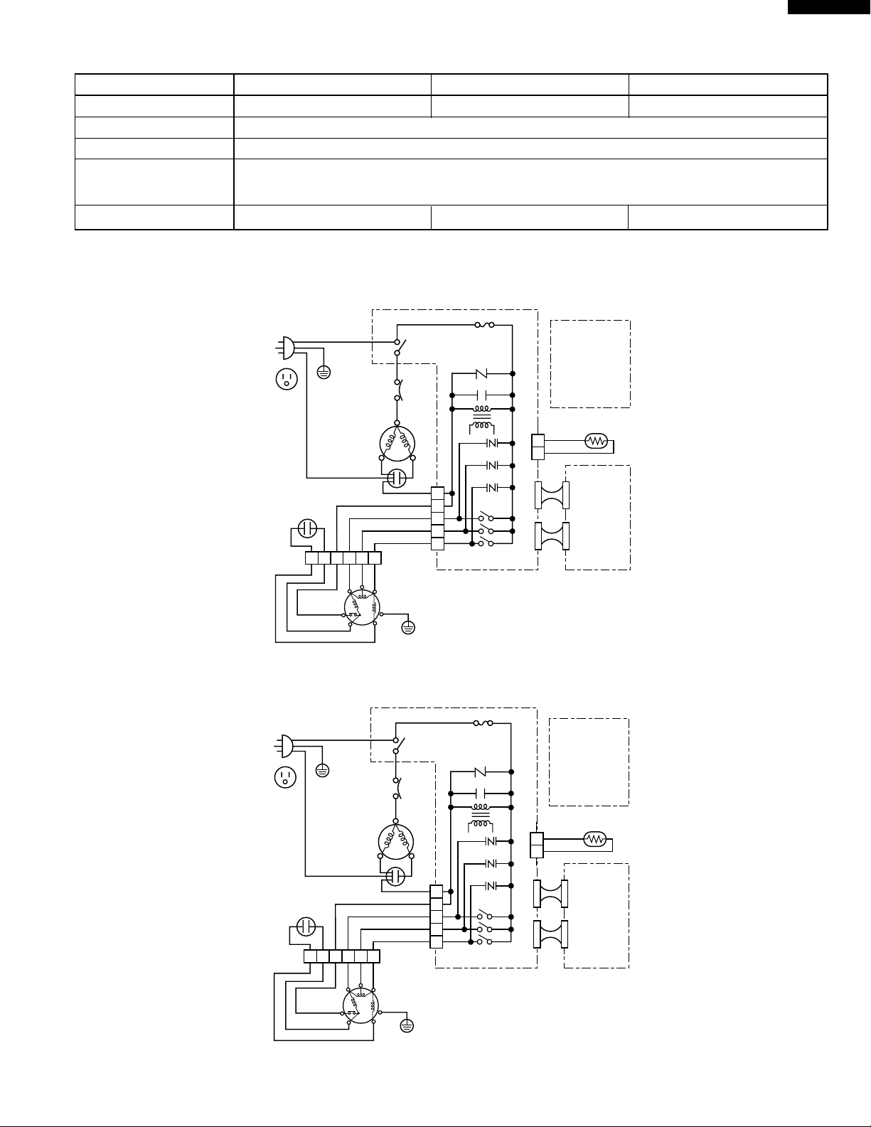
WIRING DIAGRAM
AF-R50CX
AF-R55CX
AF-R60CX
AF-R70CX
POWER SUPPLY CORD
115V 60Hz
NON RIBBED
RIBBED
RUNNING
CAPACITOR
250V 40µF
FAN MOTOR
CAPACITOR
250V 6µF
BL
BK
123654
BK
BL
THERMAL
PROTECTOR
BK
BL
GR
COMPRESSOR
GYREOR
M.C
IN
OUT
OVERLOAD
PROTECTOR
H
M
A.C
R
RE
GY
RE
OR
WH
WH
L
C
CONNECTOR
FAN MOTOR
EARTH
GR
MOTOR
BK
BK
3A 125V
MRY
S
WH
GY
FU1
CONTROL
BOARD UNIT
NR
CNR1
CNR2
8
7
1
3
5
BCN1
CNR3
C1
TR
BCN2
RY1
RY2
RY3
BCN3
WIRE COLOR
: BLACK
BK
: BLUE
BL
: RED
RE
: WHITE
WH
: GREEN
GR
: GRAY
GY
: ORANGE
OR
THERMISTOR
CN1
(
ROOM TEMP
YELLOW TH1
CN2
CN3
)
DISPLAY
BOARD
UNIT
Figure W-1. Wiring diagram for AF-R50CX, AF-R55CX and AF-R70CX
POWER SUPPLY CORD
115V 60Hz
NON RIBBED
RIBBED
RUNNING
CAPACITOR
250V 25µF
FAN MOTOR
CAPACITOR
250V 6µF
BL
BK
123654
BK
BL
THERMAL
PROTECTOR
BK
BL
GR
COMPRESSOR
GYREOR
M.C
IN
OUT
OVERLOAD
PROTECTOR
H
M
A.C
R
RE
GY
RE
OR
WH
WH
L
C
CONNECTOR
FAN MOTOR
EARTH
GR
MOTOR
BK
BK
3A 125V
MRY
S
WH
GY
FU1
CONTROL
BOARD UNIT
NR
CNR1
CNR2
8
7
1
3
5
BCN1
CNR3
C1
TR
BCN2
RY1
RY2
RY3
BCN3
WIRE COLOR
: BLACK
BK
: BLUE
BL
: RED
RE
: WHITE
WH
: GREEN
GR
: GRAY
GY
: ORANGE
OR
THERMISTOR
CN1
(
ROOM TEMP
YELLOW TH1
CN2
CN3
)
DIS
Figure W-2. Wiring diagram for AF-R60CX
3
AF-R50CX
AF-R55CX
AF-R60CX
AF-R70CX
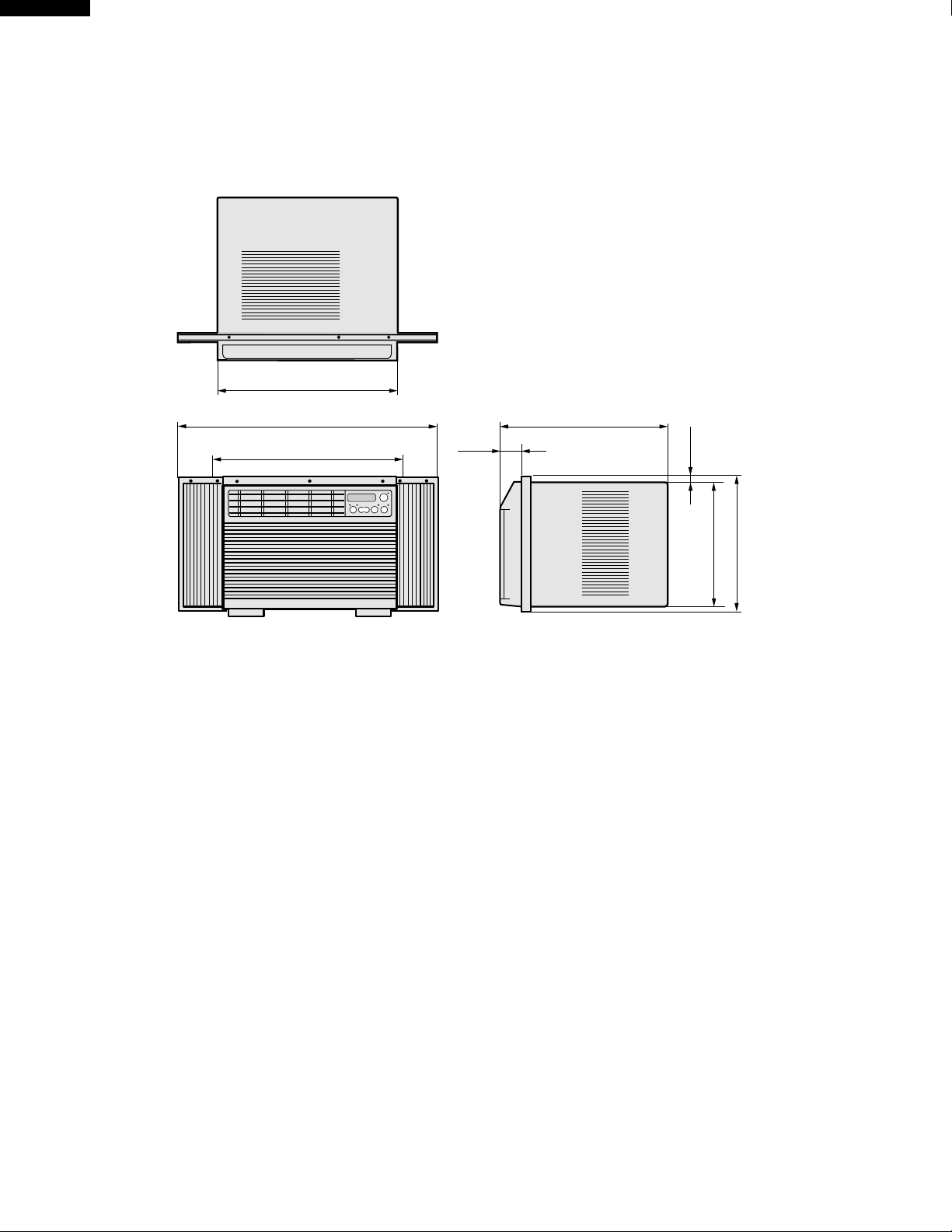
EXTERNAL DIMENSIONS.
17-23/32"
33-7/16" (full opened)
21-21/32" (full closed)
4-1/8"
15-1/4"
1-15/32"
13-5/8"
15-11/16"
4
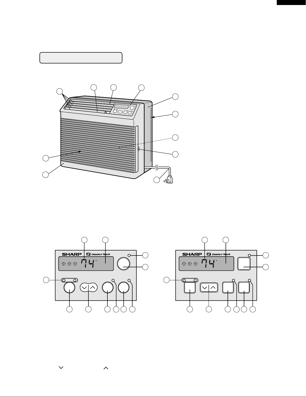
PARTS NAMES
UNIT
OPERATION INSTRUCTIONS
AF-R50CX
AF-R55CX
AF-R60CX
AF-R70CX
3
4
2
1
CONTROL PANEL
AF-R50CX, R60CX, R70CX
5
6
7
1Front Cabinet
2Air Inlet (Indoor Side)
3Horizontal Louvers
4Vertical Louvers
8
5Air Outlet (Indoor Side)
6Control Panel
7Rear Cabinet
9
8Air Inlet (Outdoor side)
9Filter (Pull the filter handle
10
to the right to remove.)
0Filter Handle
qPower Cord
11
AF-R55CX
2
1
11
F
hr
3
COOL / FAN TEMP
SELECTOR
4
5
TIMER
ON/OFF
POWER
ON/OFF
ENERGY
SAVER
6
8
7
10
9
1Receiver window for remote control signal
2Display
3SELECTOR indicator
4SELECTOR pad
5TEMPERATURE setting pad
----Lower temp. ----Raise temp.
2
1
11
F
hr
3
COOL / FAN TEMP
SELECTOR
4
5
TIMER
ON/OFF
POWER
ON/OFF
ENERGY
SAVER
6
8
7
10
9
6TIMER ON/OFF pad
7TIMER indicator
8ENERGY SAVER pad
9ENERGY SAVER indicator
0POWER ON/OFF pad
qPOWER indicator
5
AF-R50CX
AF-R55CX
AF-R60CX
AF-R70CX
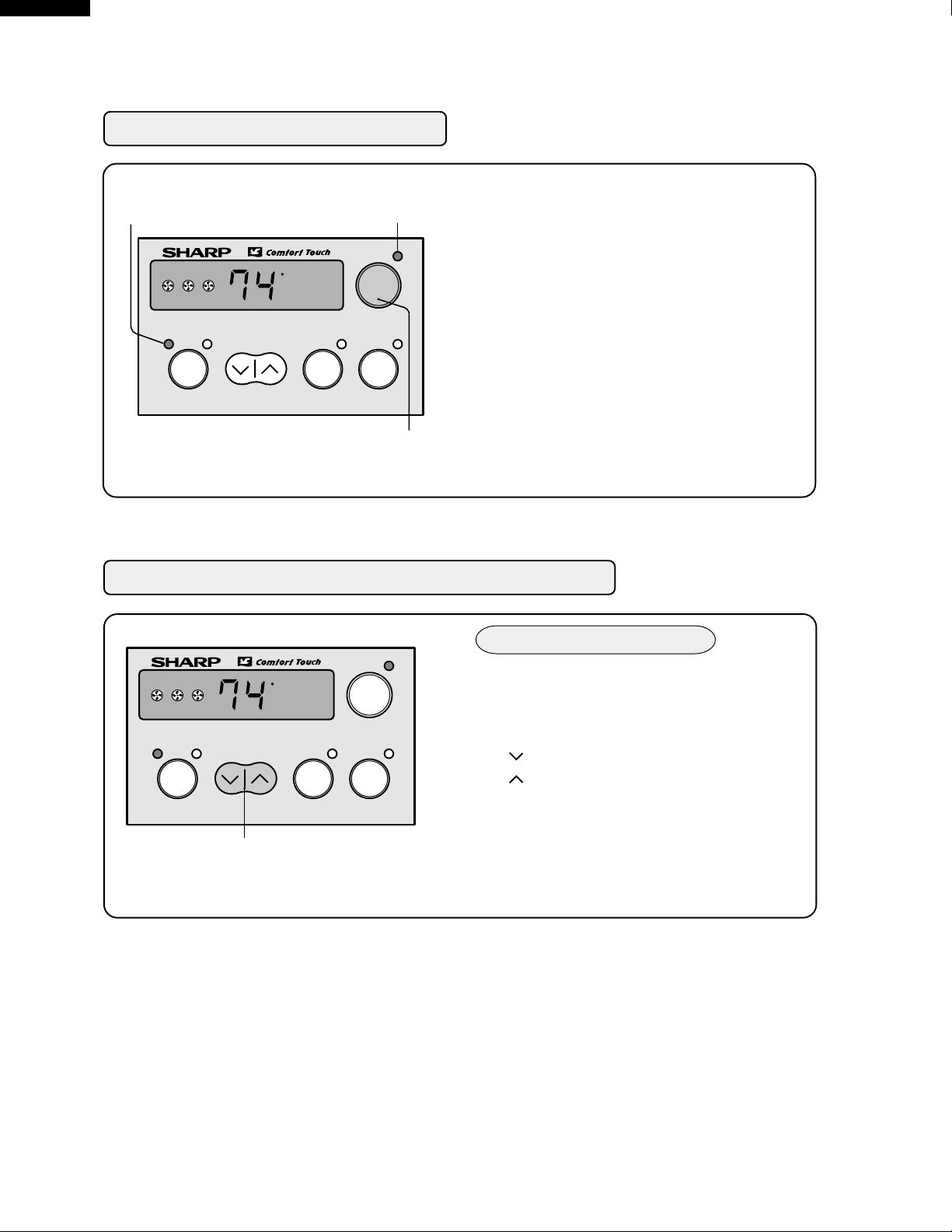
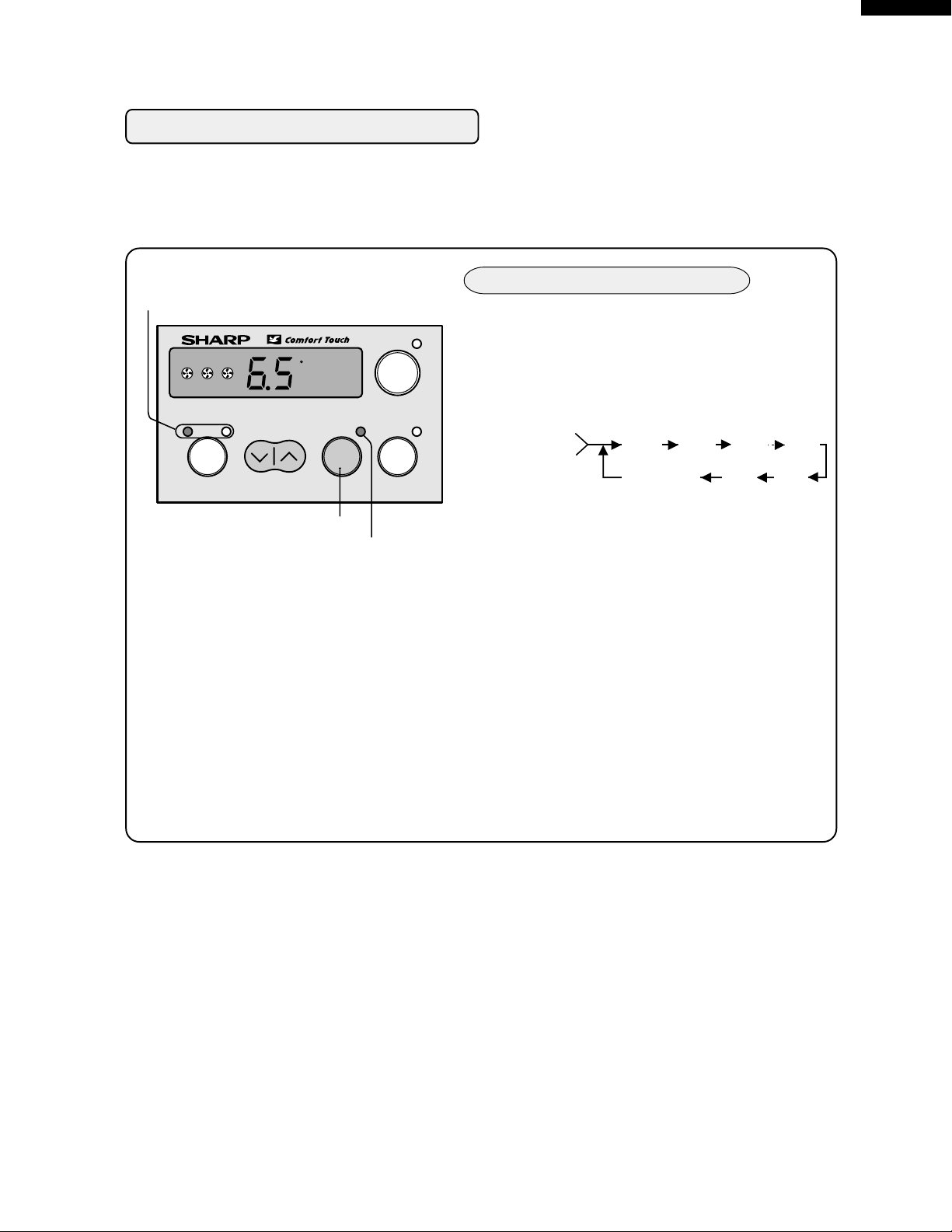
COOLING OPERATION
SELECTOR indicator
POWER
indicator
Touch POWER ON/OFF pad.
1
• The unit is preset at 74°F and HIGH
COOL. This will show in the display
when the power is first turned on.
COOL / FAN TEMP
SELECTOR
F
hr
TIMER
ON/OFF
POWER
ON/OFF
ENERGY
SAVER
• POWER indicator and SELECTOR
indicator (COOL) will light.
To turn off the unit, touch POWER
2
ON/OFF pad again
• POWER indicator and SELECTOR
POWER ON/OFF pad
indicator will go off.
TO CHANGE TEMPERATURE SETTING
During cooling operation
.
Touch the TEMPERATURE setting pad to
adjust the temperature setting.
---Lower temp.
---Raise temp.
COOL / FAN TEMP
SELECTOR
F
hr
TIMER
ON/OFF
POWER
ON/OFF
ENERGY
SAVER
• Temperature can be set within the range
of 64°F to 86°F.
TEMPERATURE setting pad
• Display will change as you touch
the pad.
NOTE:
• The latest temperature setting will be memorized and will appear on the display the next time
the unit is turned on.
• In cases of power outages or when the unit is disconnected; when the power is restored or the
unit is plugged in, the unit and display will return to the preset conditions of 74°F and HIGH
COOL. The unit will not automatically turn back on. The user must touch POWER ON/OFF to
resume opertion.
6
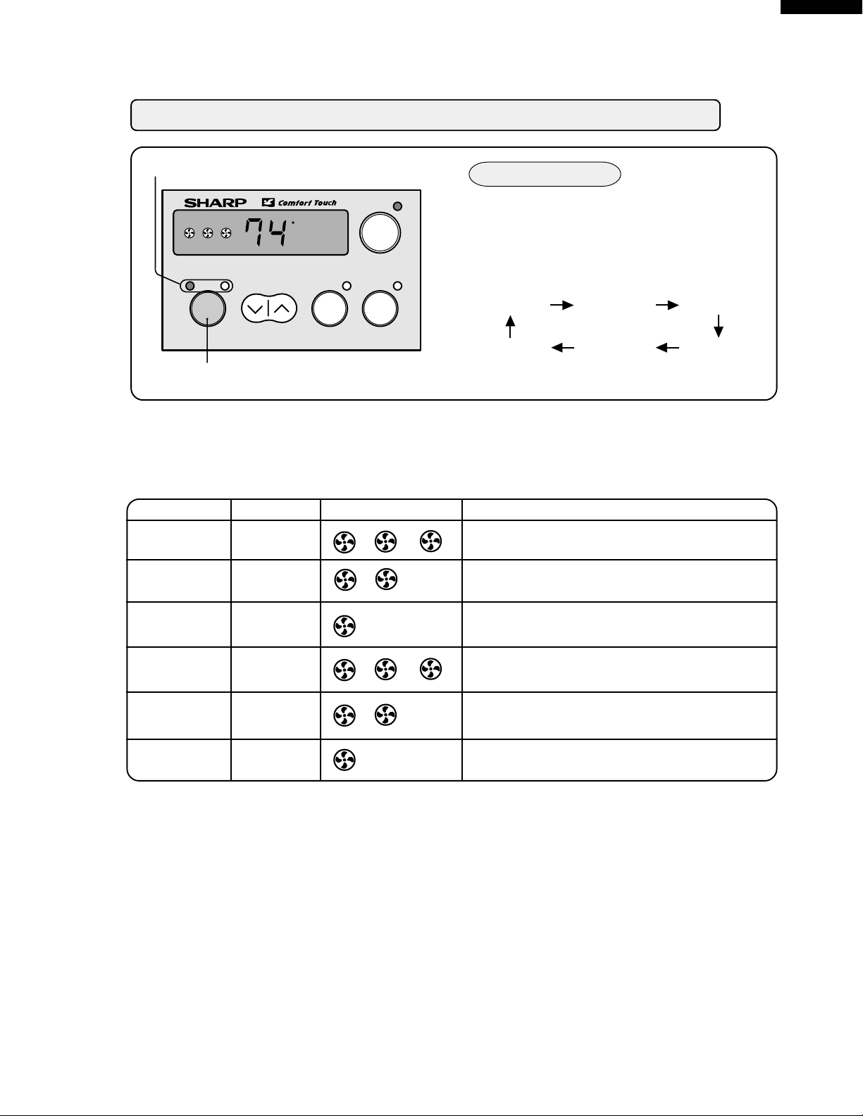
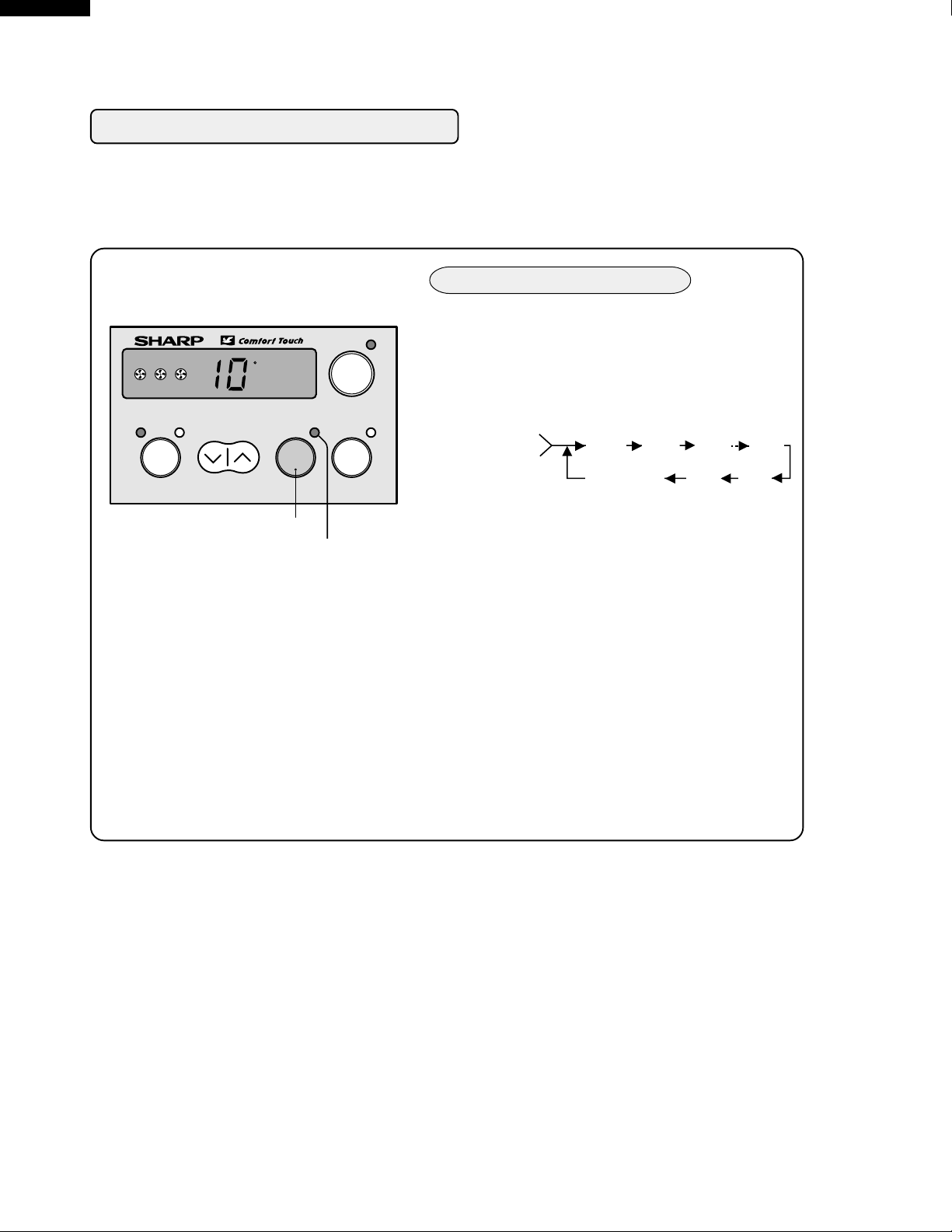
TO CHANGE FAN SPEED AND OPERATION MODE
AF-R50CX
AF-R55CX
AF-R60CX
AF-R70CX
SELECTOR indicator
COOL / FAN TEMP
SELECTOR
F
hr
TIMER
ON/OFF
POWER
ON/OFF
ENERGY
SAVER
SELECTOR pad
NOTES ON OPERATION MODE:
MODE
HIGH COOL
SELECTOR DISPLAY
COOL
During operation
Touch SELECTOR pad and select the
operation mode and fan speed.
• SELECTOR indicator and display will light
in order as you touch.
HIGH COOL MED COOL
MED FANLOW FAN
Cooling operation with high fan speed.
LOW COOL
HIGH FAN
MED COOL
LOW COOL
HIGH FAN
MED FAN
LOW FAN
COOL
COOL
FAN
FAN
FAN
Cooling operation with medium fan speed.
Cooling operation with low fan speed.
Fan only operation with high fan speed.
Fan only operation with medium fan speed.
Fan only operation with low fan speed.
• The latest operation mode will be memorized and the selector indicator and display will light
when the unit is turned on.
• In fan only operation, the temperature display will go off.
• When the SELECTOR is changed to fan only operation from cooling operation, it will take 5
seconds for the compressor to stop.
7
AF-R50CX
AF-R55CX
AF-R60CX
AF-R70CX
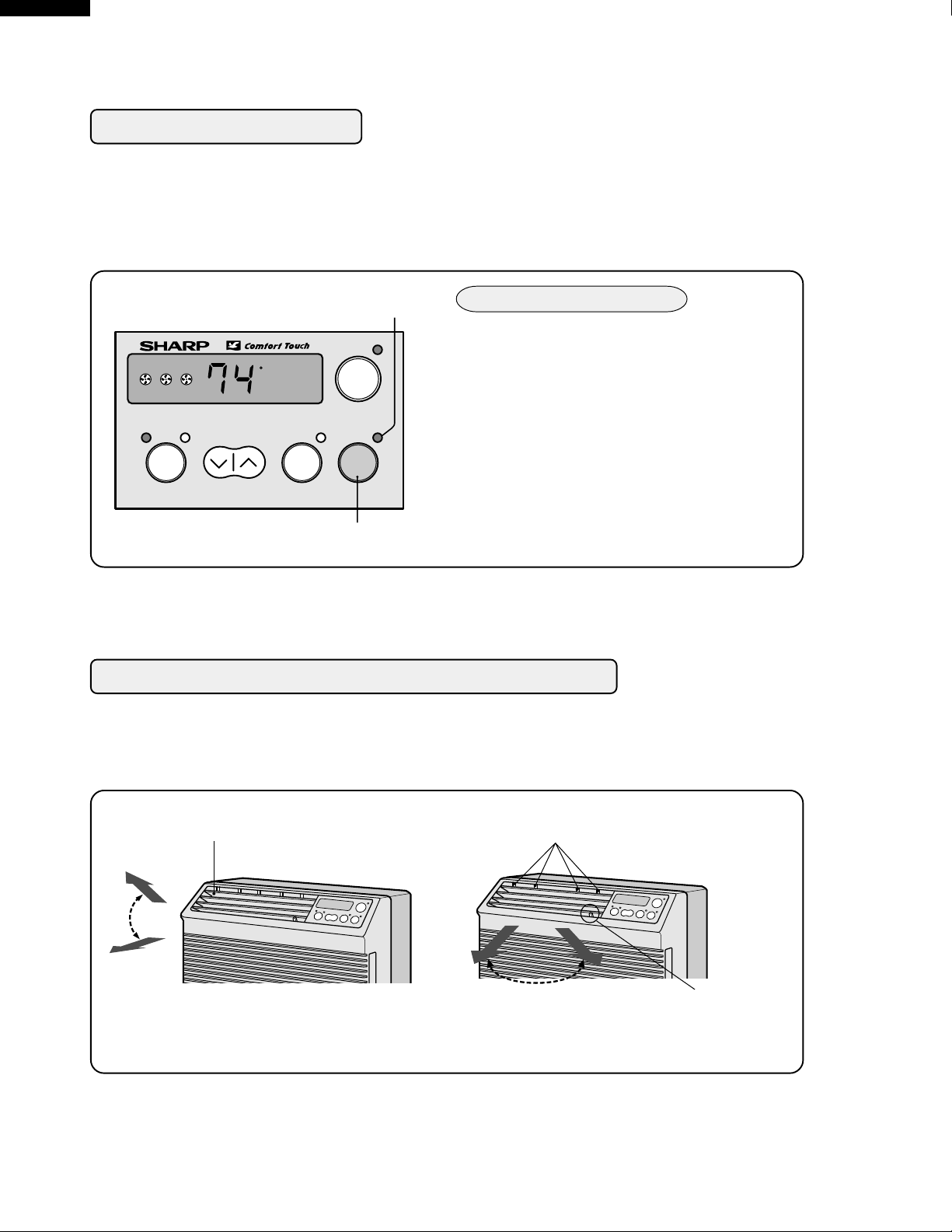
ENERGY SAVER
During normal operation, the thermostat automatically controls cooling and the fan runs continuously.
When the ENERGY SAVER is selected, the thermostat automatically controls cooling and the fan
automatically stops when the compressor is not operating. (Fan will stop 30 seconds after the
compressor stops. After the fan stops, the fan is programmed to rotate for approx. 2 minutes to
detect room temperature. This will occur within a 20 min time span.)
ENERGY SAVER indicator
COOL / FAN TEMP
SELECTOR
F
hr
TIMER
ON/OFF
POWER
ON/OFF
ENERGY
SAVER
During cooling operation
Touch ENERGY SAVER pad.
1
• ENERGY SAVER indicator will light.
To cancel, touch ENERGY SAVER
2
pad again.
• ENERGY SAVER indicator will go
off.
ENERGY SAVER pad
NOTE: ENERGY SAVER cannot be set during fan only (HIGH FAN, MED FAN, LOW FAN)
operation.
TO CHANGE AIR FLOW DIRECTION
The horizontal louvers are used to adjust the UP / DOWN direction of air flow, and the vertical
louvers are used to adjust the LEFT / RIGHT direction of air flow for uniform and efficient cooling
of the room.
Horizontal louvers
Adjust UP/DOWN air flow
Vertical louvers
Lever
Adjust LEFT/RIGHT air flow
8
ON TIMER OPERA TION
• This unit has a built-in timer that can be programmed to start the unit up to 12 hours in advance.
You can set the timer to start in increments of 30 minutes (0.5 hours) up to 9.5 hours in advance
of the start time, or in 1 hour increments from 10 to 12 hours in advance of the start time.
• The unit will start automatically according to your setting.
When the unit is not operating
SELECTOR indicator
Touch the TIMER ON/OFF pad to set the delayed
start time.
1
F
hr
POWER
ON/OFF
• The time setting will change as you touch the
pad. The display will change as follows;
AF-R50CX
AF-R55CX
AF-R60CX
AF-R70CX
COOL / FAN TEMP
SELECTOR
TIMER
ON/OFF
TIMER ON/OFF pad
TIMER indicator
(If you wish to start the operation
6 hours and 30 minutes later, set
the delay time as shown above.)
ENERGY
SAVER
Preset(0.5h)
Previous setting
0.5h
CL(cancel)
1.0h
1.5h 10h
11h12h
• The timer will be set, 5 seconds after the
TIMER ON/OFF pad is touched for the last
time.
• SELECTOR indicator and TIMER indicator
will light.
• The time display will count down the
remaining time.
• The unit will start when the set time expires.
The temperature setting will be displayed.
TO CANCEL THE TIMER SETTING
Touch the TIMER ON/OFF pad again after the
timer is set, or press the TIMER ON/OFF pad
until CL(cancel) appears on the display.
NOTES FOR TIMER SETTING AND OPERATION:
• After setting the TIMER, change the temperature and fan speed settings as shown on pages 11
and 12. When the temperature is set in the timer mode, the temperature will show in the display
for 5 seconds and then return to the time display.
• The last setting used will be memorized and will appear on the display the next time you operate
the unit with the TIMER function.
• If a power failure occurs while the ON or OFF TIMER is set, the TIMER memory will be cancelled
and will not resume even after power is reinstated. The unit will not automatically start.
• OFF TIMER OPERATION can also be set with the REMOTE CONTROL.
9
AF-R50CX
AF-R55CX
AF-R60CX
AF-R70CX
OFF TIMER OPERA TION
• T
his unit has a built-in timer that can be programmed to shut the unit off up to 12 hours in advance.
You can set the timer to stop in increments of 30 minutes (0.5 hours) up to 9.5 hours in advance of
the stop time, or in 1 hour increments from 10 to 12 hours in advance of the stop time.
• The unit will stop automatically according to your setting.
When the unit is operating
1
F
hr
POWER
ON/OFF
Touch the TIMER ON/OFF pad to set the delayed
stop time.
• The time setting will change as you touch the
pad. The display will change as follows;
COOL / FAN TEMP
SELECTOR
TIMER
ON/OFF
ENERGY
SAVER
TIMER ON/OFF pad
TIMER indicator
(If you wish to stop the operation
10 hours later, set the delay time
as shown above.)
Preset(0.5h)
Previous setting
0.5h
CL(cancel)
1.0h
1.5h 10h
11h12h
• The timer will be set, 5 seconds after the
TIMER ON/OFF pad is touched for the last
time.
• TIMER indicator will light.
• The time display will count down the
remaining time.
• The unit will stop when the set time expires.
All indicators and displays will go out.
TO CANCEL THE TIMER SETTING
Touch the TIMER ON/OFF pad again after the
timer is set or, press the TIMER ON/OFF pad until
CL(cancel) appears on the display.
10
USING THE REMOTE CONTROL
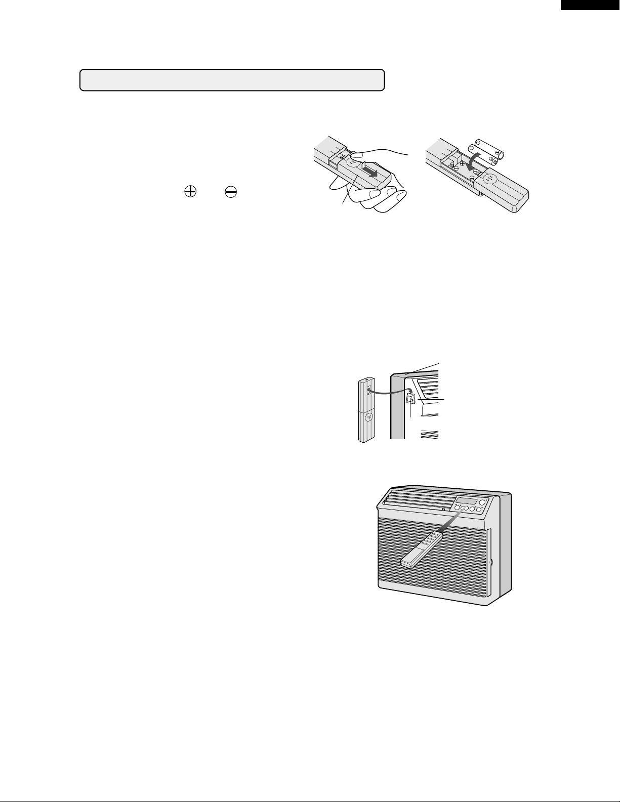
INSTALLING BATTERIES
Use two size-AAA (R03) batteries.
Remove the battery compartment cover.
1
Insert the batteries in the compartment,
2
making sure the and polarities
are properly aligned.
Replace the cover.
3
NOTES:
• The battery life is approximately one year with normal use.
• When you replace the batteries, always use two new ones of the same type.
• If the remote control does not operate normally after replacing the batteries, take out the
batteries and replace them again after 30 seconds.
• If you will not be using the unit for a long time, remove the batteries from the remote control.
Battery compartment cover
AF-R50CX
AF-R55CX
AF-R60CX
AF-R70CX
ATTACHING THE REMOTE CONTROL HOOK
• Remove the backing from the remote control hook.
• Attach the hook onto the left side of the unit's front
cabinet.
• To prevent loss, hook the remote control on the front
cabinet when not in use.
Remote control hook
Rear Cabinet
Front Cabinet
HOW TO USE THE REMOTE CONTROL
Point the remote control towards the unit's receiver window and press the desired button. A
beep will sound when the unit receives the signal.
• Make sure no objects, such as curtains, block the
receiver window.
• The remote control operates from up to 20 feet (6
meters) away.
• The beep will also sound when each pad on the
control panel is touched.
CAUTION:
• Do not expose the receiver window to direct sunlight. This can adversely affect its operation. In
such case, close the curtains to block the sunlight.
• Use of a fluorescent lamp in the same room may interfere with the transmission of the signal.
• The unit may be affected by signals emitted from the remote control of a television, VCR or other
equipment used in the same room.
• Do not leave the remote control exposed to direct sunlight or near a heater. Protect the remote
control from moisture and shock which can discolor or damage it.
11
AF-R50CX
AF-R55CX
AF-R60CX
AF-R70CX
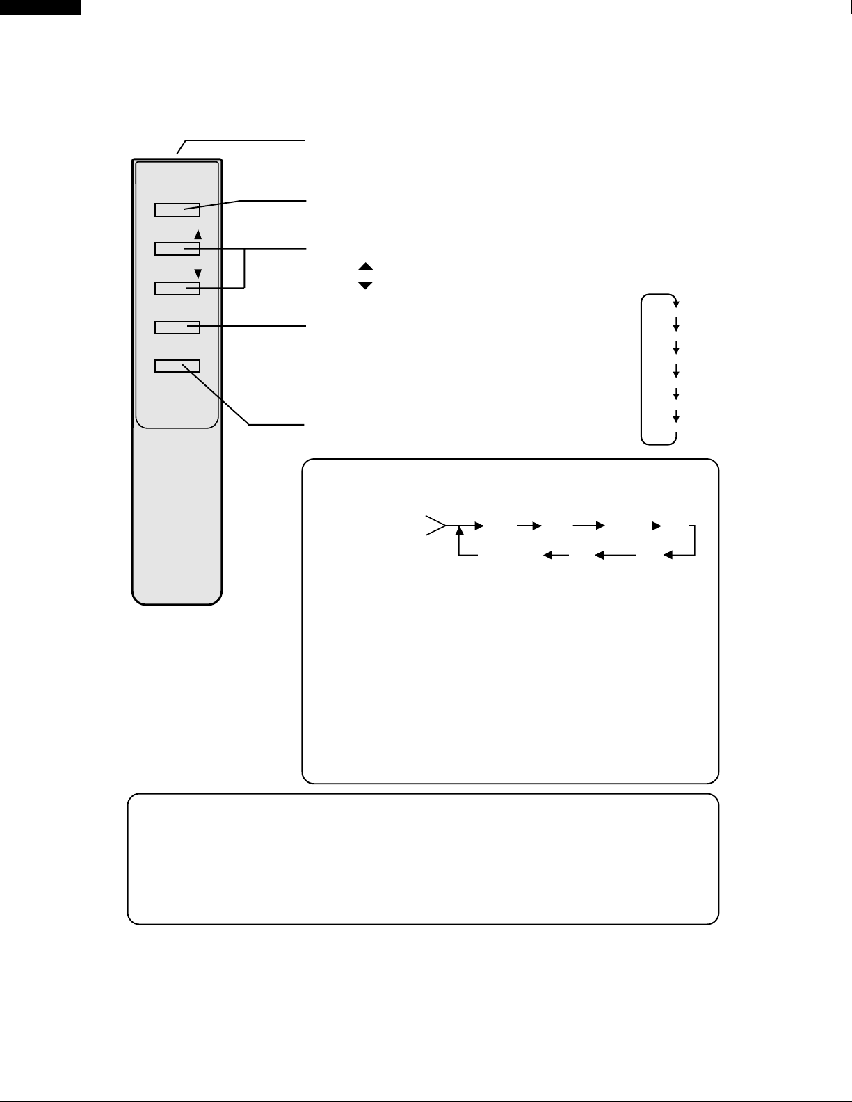
OPERATING WITH THE REMOTE CONTROL
TRANSMITTER
POWER
ON/OFF
TEMP.
POWER ON/OFF button
Push to start or stop the operation.
TEMP.
SELECTOR
SET TIMER/OFF
TEMP.
TEMP.
SELECTOR button
Push to change fan speed and operation
mode.
Fan speed and operation mode selections are shown to the right.
SET TIMER/OFF button
---Raise temp. setting 1°F at a time.
---Lower temp. setting 1°F at a time.
HIGH COOL
MED COOL
LOW COOL
HIGH FAN
MED FAN
LOW FAN
Push to set delay "OFF" timer during operation.
• The time setting will change as you push the button. The display
will change as follows;
Preset(0.5h)
Previous setting
0.5h
CL(cancel)
• The last OFF time setting is memorized by the unit and will
appear on the display when the button is pushed.
• The timer will be set, 5 seconds after the SET TIMER/OFF button
is pushed for the last time.
• If you wish to cancel the timer, push the SET TIMER/OFF button
again after the time is set or, push the SET TIMER/OFF button
until CL (cancel) appears on the display. A double beep will
sound when the timer is cancelled.
• The "ON" TIMER cannot be set with the remote control.
It can only be activated by the TIMER ON/OFF pad on the unit's
control panel ( See page 9).
1.0h
1.5h 10h
11h12h
To change temperature setting when ON/OFF timer is in use
1. Push a TEMPERATURE setting button.
The current set temperature will be recalled on the unit's display.
2. Use the TEMPERATURE setting buttons to set the new temperature.
The new set temperature will show on the display for 5 seconds and return to
the time display.
12
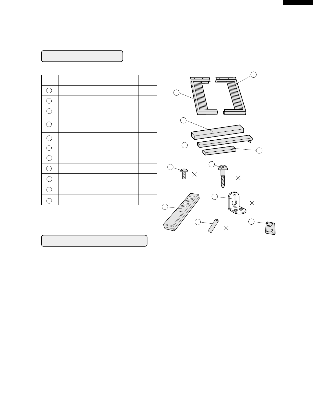
ACCESSORIES
No.
Accessories Q'ty
AF-R50CX
AF-R55CX
AF-R60CX
AF-R70CX
1
1
2
3
4
5
6
7
8
9
10
11
Right closure assembly 1
Left closure assembly 1
Window sash foam seal 1
Window sash foam seal 1
(adhesive type)
Bottom gasket 1
Screws (L=1", 25.4mm) 7
Screws (L=
13
/32", 10mm) 6
Base pan angle 2
Remote control 1
Battery 2
Remote control hook 1
2
3
4
5
6
6
7
7
8
9
10
2
2
11
SUGGESTED TOOLS
1. Screw driver (medium size Phillips)
2. Tape measure or ruler
3. Knife or scissors
13
AF-R50CX
AF-R55CX
AF-R60CX
AF-R70CX
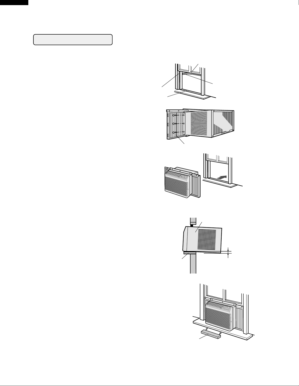
INSTALLATION
WARNING: Make sure the unit is turned off and unplugged before working.
Cut the window sash foam seal (adhesive
type) to the proper length and attach it to
1
the underside of the window sash.
Insert the right closure assembly and the
left closure assembly into the top angle
2
and the bottom channels.
Secure the right and left closure to the
cabinet with six of the provided screws.
13
/32", 10mm)
(L=
Jamb
Sill
Sash
Window sash foam seal
(adhesive type)
Closure assembly
Open the window sash and place the air
conditioner on the sill.
3
Balance the unit on the sill and close the
window sash securely behind the top
angle.
WARNING:
At this step, make sure the unit is inclined
approximately 1 cm (
If the unit is not properly inclined, the water
collected in the bottom tray during operation will not drain properly and may flow into
the room where the air conditioner is installed.
Insert the bottom gasket into the space
between the window sill and the bottom of
4
the unit to seal outside air.
3
/8") to the back.
sill
unit
incline backwards approximately
1cm (3/8")
If there is space between the bottom
channel and the sill, fill the gap with a thin
board or other hard filler.
14
Bottom gasket
 Loading...