

Page 1
SERVICE MANUAL
AE-6B
CHASSIS
MODEL
KV-28LS60B
KV-28LS60E
KV-28LS60U
COMMANDER DEST CHASSIS NO.
RM-932 FR SCC-Q83C-A
RM-932 ESP SCC-Q81E-A
RM-932 UK SCC-Q84D-A
MODEL
KV-32LS60B
KV-32LS60E
KV-32LS60K
KV-32LS60U
COMMANDER DEST CHASSIS NO.
RM-932 FR SCC-Q83B-A
RM-932 ESP SCC-Q81D-A
RM-932 OIRT SCC-Q82C-A
RM-932 UK SCC-Q84C-A
KV-28/32LS60
- 1 -
RM-932
Page 2
AE-6B SELF DIAGNOSTIC SOFTWARE
The identification of errors within the AE-6B chassis is triggered in one of two ways :- 1: Busy or 2: Device failure to respond to IIC. In the
event of one of these situations arising the software will first try to release the bus if busy (Failure to do so will report with a continuous
flashing LED) and then communicate with each device in turn to establish if a device is faulty. If a device is found to be faulty the relevant
device number will be displayed through the LED (Series of flashes which must be counted) See table 1, non fatal errors are reported using this
method.
Each time the software detects an error it is stored within the NVM. See Table 2.
Table 1
egasseMrorrE
rorreoN00
devreseR10
)noitcetorPtnerruCrevO(PCO20
noitcetorPegatloVrevO30
cnySlacitreVoN40
norewoptarorrERKI50
norewoptaegdelwonkcasubCIIonMVN70
noitcetorPlatnoziroH80
norewoptaegdelwonkcaonrenuT90
rorrErossecorPdnuoS01
devreseR11
rorrEetarnacS21
rorrECAD31
rorrEdnekcaB41
rorrEecnegrevnoCcimanyD51
rorrEPIP61
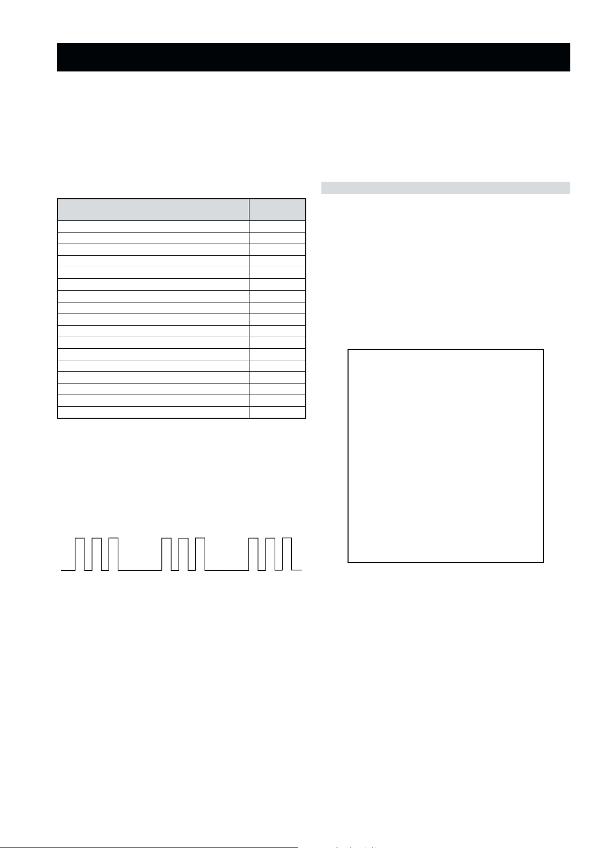
Flash Timing Example : e.g. error number 3
StBy LED
ON ON ON
OFF
OFF
norewoptawolsenilatadro/dnakcolcsubCII60
How to enter into Table 2
DEL
edoC
1. Turn on the main power switch of the TV set.
2. Program Remote Commander for Operation in Service
Mode. [See Page 22].
3. Press ‘VIDEO’ ‘VIDEO’ > ‘MENU’ on the Remote
Commander.
4. Using the Remote Commander, Scroll to the ‘Error Menu’
item using the down arrow key, then press the right arrow
key.
5. The following table will be displayed indicating the error
count.
Table 2
UNEMRORRE
20E
30E
40E
50E
60E
70E
80E
90E
01E
11E
21E
31E
41E
51E
61E
SRUOH
SETUNIM
PCO
PVO
CNYSV
RKI
CII
MVN
TORPH
RENUT
PDNUOS
ETARNACS
CAD
DNEKCAB
NOCNYD
PIP
EMITGNIKROW
)552,0(
0
)552,0(
0
)552,0(
0
)552,0(
0
)552,0(
0
)552,0(
0
)552,0(
0
)552,0(
0
)552,0(
0
)552,0(
0
)552,0(
0
)552,0(
0
)552,0(
0
)552,0(
0
)552,0(
0
41
7
Note: To clear the error count data press ‘80’ on the Remote
commander.
- 7 -
Page 3
4-1. Electrical Adjustments
SECTION 4 CIRCUIT ADJUSTMENTS
Service adjustments to this model can be performed using the
supplied remote Commander RM-932.
Programming the Remote Commander for
Operation in Service Mode
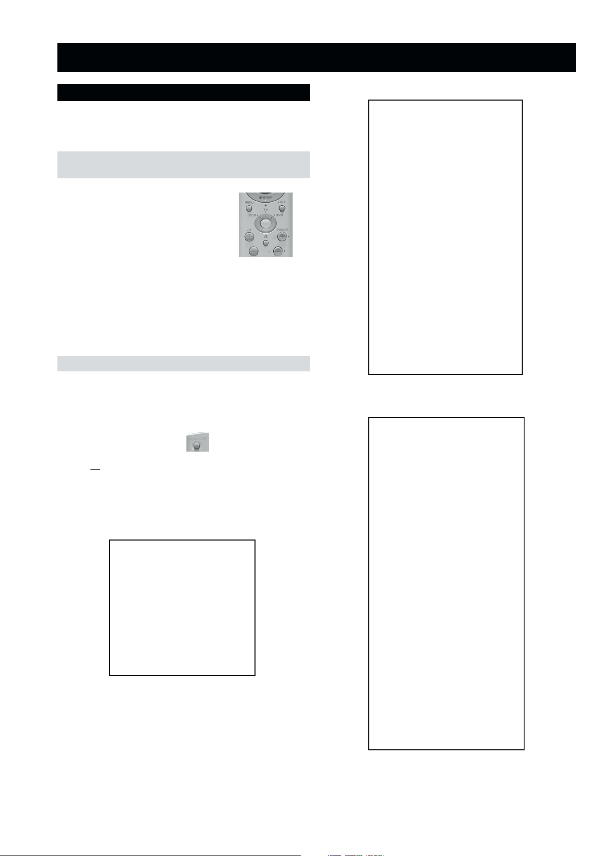
1. Press the VCR/TV/DVD button until the
TV LED lights.
2. Press and hold the yellow button for
approx. 5 seconds until the TV LED
flashes quickly.
3. Press 99999. All three LED’s should light.
The remote commander is now set to Service Mode.
4. To return the remote commander to normal operation mode
repeat steps 1. and 2. then press 00000. All three LED’s
should light.
The remote commander is now set to normal mode.
Setting the TV into Service Mode
1. Program the remote commander for operation in Service
Mode as described above.
YRTEMOEG
HTLBA
EDOMLBA
LBAP
EZISV
NOITISOPV
PMOCV
NILV
NOITCERROCS
EZISH
PMANIP
NIPRENROCPU
NIPM
NIPRENROCOL
MUIZEPART
NOITISOPH
WOBCFA
ELGNACFA
KLBTFEL
KLBTHGIR
TCEPSAV
1MITBKA
2MITBKA
RKI
GNH
GNV
)3,0(
)3,0(
)3,0(
)3,0(
)3,0(
)1,0(
0
0
)51,0(
)36,0(
)36,0(
)51,0(
)51,0(
)36,0(
)36,0(
)36,0(
)36,0(
)51,0(
)36,0(
)51,0(
)51,0(
)36,0(
)36,0(
)36,0(
51
53
33
1
7
7
44
23
92
2
92
2
04
8
9
43
71
74
2
0
1
0
0
2. Turn on the TV main power switch.
3. Press the video standby button on the remote
commander twice.
‘TT ’ will appear in the upper right corner of the screen.
Other status information will also be displayed.
4. Press ‘MENU’ on the remote commander to obtain the
following menu on the screen.
yrtemoeG
ecivreS
etarnacS
CAD
.vnoC.nyD
PiP
dnuoS
tsujdaFI
uneMrorrE
)1002nuJ(41.0vB6EA
hFFhFFatadyrotcaF
G1143PSM:eciveDPSM
5. Move to the corresponding adjustment item using the
up or down arrow buttons on the Remote Commander.
6. Press the right arrow button to enter into the required menu item.
7. Press the ‘Menu’ button on the Remote Commander to quit the
Service Mode when all adjustments have been completed.
.VNOC.NYD
EGNAR
LpuY
LAV
LwolY
LAV
LpuWOBM
LAV
LwolWOBM
LAV
LPMAH
LAV
RpuY
LAV
RwolY
LAV
RpuWOBM
LAV
RwolWOBM
LAV
RPMAH
LAV
YPU
LAV
YWOL
LAV
TATSH
LAV
RROCPU
LAV
RROCWOL
LAV
)36,0(
)1,0(
)36,0(
)1,0(
)36,0(
)1,0(
)36,0(
)1,0(
)36,0(
)1,0(
)36,0(
)1,0(
)36,0(
)1,0(
)36,0(
)1,0(
)36,0(
)1,0(
)36,0(
)1,0(
)36,0(
)1,0(
)36,0(
)1,0(
)36,0(
)1,0(
)36,0(
)1,0(
)36,0(
)1,0(
)36,0(
36
0
03
0
13
0
13
0
23
0
73
0
03
0
03
0
23
0
23
0
63
0
13
0
33
0
33
0
43
0
91
·
Note :
· After carrying out the service adjustments, to prevent the
customer accessing the ‘Service Menu’ switch the TV set
OFF and then ON.
- 22 -
Page 4
TSUJDAFI
UNEMRORRE
etumotuA
niaGoiduA
gnitaGL
ECIVRES
LOCBUS
EUHBUS
PRAHSBUS
THGIRBBUS
TNOCBUS
EVIRD-R
EVIRD-G
EVIRD-B
FFOTUCR
FFOTUCG
FFOTUCB
TXTrB
DSOrB
)36,0(
)36,0(
)36,0(
)36,0(
)51,0(
)36,0(
)36,0(
)36,0(
)36,0(
)36,0(
)36,0(
)51,0(
)51,0(
1
0
0
jdA
13
03
31
21
05
jdA
jdA
82
42
64
7
01
20E
30E
40E
50E
60E
70E
80E
90E
01E
11E
21E
31E
41E
51E
61E
EMITGNIKROW
SRUOH
SETUNIM
PCO
PVO
CNYSV
RKI
CII
MVN
TORPH
RENUT
PDNUOS
ETARNACS
CAD
DNEKCAB
NOCNYD
PIP
)552,0(
0
)552,0(
0
)552,0(
0
)552,0(
0
)552,0(
0
)552,0(
0
)552,0(
0
)552,0(
0
)552,0(
0
)552,0(
0
)552,0(
0
)552,0(
0
)552,0(
0
)552,0(
0
)552,0(
0
41
7
Sub Brightness Adjustment
1. Input a Monoscope pattern.
2. Program the Remote Commander for operation in Service Mode.
CAD
[ See Page 22 ].
3. Press ‘VIDEO’ ‘VIDEO’ 13 on the Remote Commander.
GIFNOC
TNOCNIPM
NILH
PARTH
LIOC.TOR
HPSUCOHP
)552,0(
)552,0(
)552,0(
)552,0(
)552,0(
00000000
69
38
721
031
09
4. Adjust the ‘Sub-Brightness’ data so that there is barely a
difference between the 0 IRE and 10 IRE signal levels.
Sub Contrast Adjustment
1. Input a video signal that contains a small 100% white area on a
black background.
2. Connect an digital voltmeter to Pin 10 of J7378 [C Board].
3. Program the Remote Commander for operation in Service Mode.
DNUOS
N-M
D-M
S-M
M-S
M-D
M-N
EBB
1B
2B
3B
4B
5B
LWS
FWS
DACMACIN
rorrEMACIN
oeretS
)115,0(
)1-,821-(
)721+,0+(
)721+,0+(
)1-,821-(
)3201,0(
)86+,0+(
)69+,69-(
)69+,69-(
)69+,69-(
)69+,69-(
)69+,69-(
)0+,821-(
)04+,5+(
)7402,0(
)721+,821-(
002
02-
02+
01+
01-
694
82+
0+
0+
0+
0+
0+
0+
03+
10001
0
0+
[ See Page 22 ].
4. Adjust the Sub-Contrast [ Using ‘VIDEO’ ‘VIDEO’ ‘11’ ] to
obtain a voltage of 105 +/- 5V.
Sub Colour Adjustment
1. Receive a PAL colour bar signal.
2. Connect an oscilloscope to Pin 6 of CN7001 [A Board].
3. Program the Remote Commander for operation in Service Mode.
[ See Page 22 ].
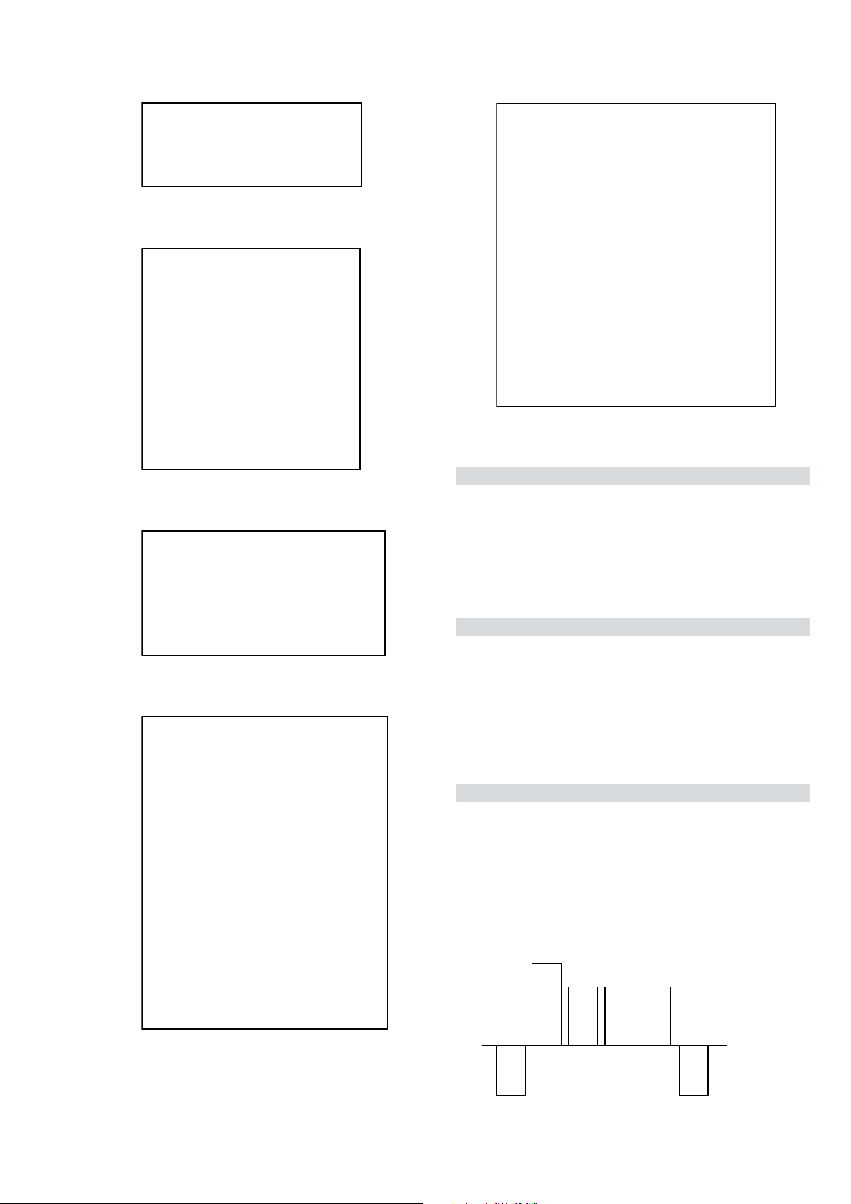
4. Adjust the ‘Sub Colour’ [ Using ‘VIDEO’ ‘VIDEO’ ‘12’ ] so
that the Cyan, Magenta and Blue colour bars are of equal levels
as indicated below.
Same Level
sutatS0110000000
B-Out Waveform
- 23 -
Page 5
Deflection System Adjustment
72
RKEDAnoitanitseD
82
RKEDAnoitanitseD
13
elbasiD/elbanEffotuhSotuA
63
tsetNO/FFO)MV(noitaludoMyticoleV
14
MVNesilaitini-eR
34
dnuosAlauDtceleS
44
dnuosBlauDtceleS
54
dnuosonoMtceleS
64
dnuosoeretStceleS
84
nigrivnonsaMVNteS
94
nigrivsaMVNteS
35
elbasiD/elbanEnoitaludomrevOMF
55
)SPLA/YNOS(noitcelesrenuT
95
stracS2roPIP+stracS3ledoMtceleS
86
)melborpN(erusaemretnuoc62XelbasiD/elbanE
37
)47.6/5.6(metsys2K/DnotiewZelbanE
47
)47.5/5.6(metsys3K/DnotiewZelbanE
87
thgirllufecnalaB
97
tfelllufecnalaB
78
tsetsyeklacoL
99
unememiTgnikroWdnarorrEyalpsiD
00
ffoedom'TT'
10
mumixamerutciP
20
muminimerutciP
30
%53otemuloVenohpdaeh/rekaepsteS
40
%05otemuloVenohpdaeh/rekaepsteS
50
%56otemuloVenohpdaeh/rekaepsteS
60
%08otemuloVenohpdaeh/rekaepsteS
70
edomgniegA
80
noitidnoCgnippihS
11
tnemtsujdaerutcipbuS
21
tnemtsujdaruolocbuS
31
tnemtsujdassenthgirBbuS
41
tnemtsujdanoitisoPHtxeT
51
tseTlioCnoitatoR
61
%05levelerutciP
91
elbasiD/elbanEedoMyrotcaF
12
RKEDAnoitanitseD
22
LBnoitanitseD
32
RKEDAnoitanitseD
42
UnoitanitseD
52
RKEDAnoitanitseD
62
LBnoitanitseD
4-2. TEST MODE 2:
1. Program the Remote Commander for operation in Service Mode.
[ See Page 22 ] and enter into the ‘Geometry’ service menu.
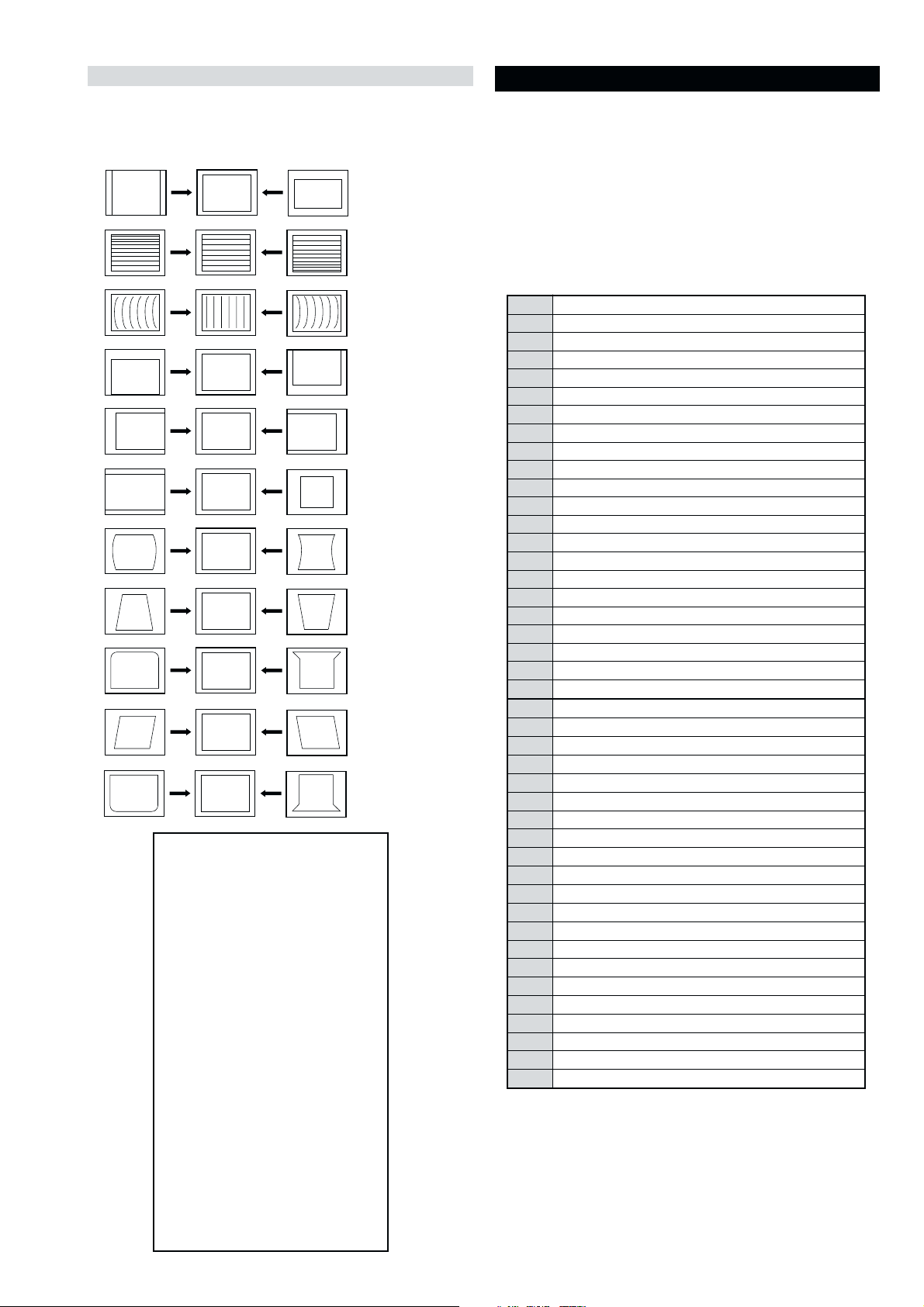
2. Select and adjust each item in order to obtain the optimum image.
V SIZE
V LIN
AFC BOW
V POSITION
H POSITION
H SIZE
PIN AMP
Test Mode 2 is available by rogramming the Remote Commander for
operation in Service Mode [ As shown on Page 22 ] then pressing the
‘VIDEO’ button twice, OSD ‘TT’ appears. The functions described
below are available by selecting the two numbers. To release the ‘Test
mode 2’, press 00, 10, 20 ... twice or switch the TV set into Stand-by
mode. In ‘TT Menu’ mode, it is possible to remove the Menu from
the screen by pressing the Speaker Off button once. Pressing the
Speaker OFF button a second time will cause the Menu to reappear.
The function is kept even when the menu is not displayed on
screen !!.
TRAPEZIUM
UP CORNER PIN
AFC ANGLE
LO CORNER PIN
YRTEMOEG
HTLBA
EDOMLBA
LBAP
EZISV
RKI
NOITISOPV
PMOCV
NILV
EZISH
PMANIP
NIPM
WOBCFA
KLBTFEL
1MITBKA
2MITBKA
NOITCERROCS
NIPRENROCPU
NIPRENROCOL
MUIZEPART
NOITISOPH
ELGNACFA
KLBTHGIR
TCEPSAV
GNH
GNV
)3,0(
)3,0(
)3,0(
)3,0(
)3,0(
)1,0(
0
0
)51,0(
)36,0(
)36,0(
)51,0(
)51,0(
)36,0(
)36,0(
)36,0(
)36,0(
)51,0(
)36,0(
)51,0(
)51,0(
)36,0(
)36,0(
)36,0(
51
53
33
1
7
7
44
23
92
2
92
2
04
8
9
43
71
74
2
0
1
0
0
- 24 -
Page 6
- 29 -
- 29 -
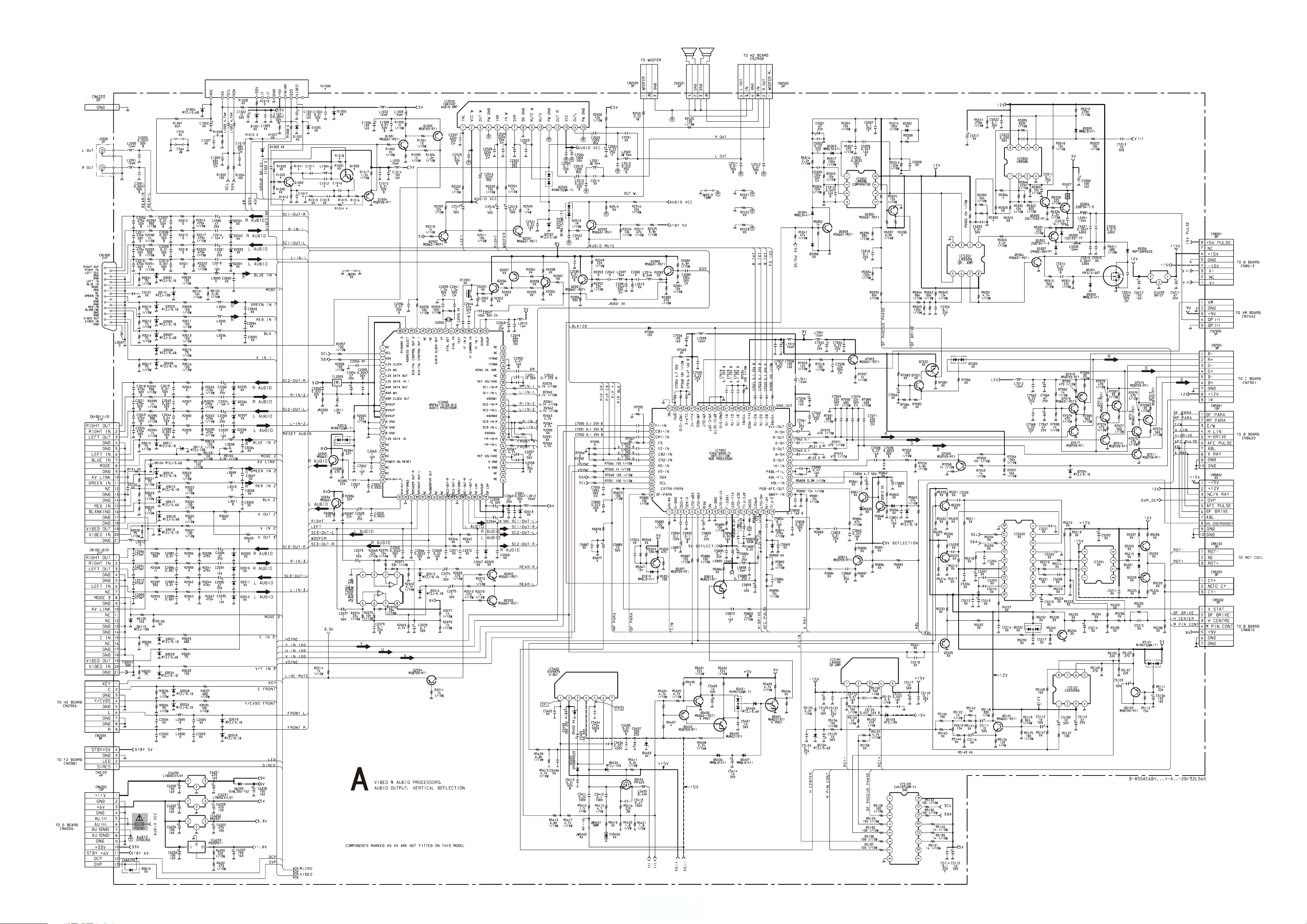
~ A Schematic [ Video & Audio Processors, Audio Output,
Vertical Deflection] page 1/2~
Page 7
~ A Board Waveforms ~
feR B06SL82 E06SL82 U06SL82 B06SL23 E06SL23 K06SL23 U06SL23
1101CV05%5FP021__V05%5FP021___
2101CV05%5FP65__V05%5FP65___
6101CV05FP05.0FP01__V05FP05.0FP01___
7101CV05%5FP86__V05%5FP86___
4001LHU81__HU81___
2001Q1TSR-106DSM__ 1TSR-106DSM___
3001QKE411CTD__ KE411CTD___
1101RW01/1%5033__W01/1%5033___
2101RW01/1%5033__W01/1%5033___
4101R_ 0TROHS0TROHS_ 0TROHS0TROHS0TROHS
5101RW01/1%5074__W01/1%5074___
6101RW01/1%5001__W01/1%5001___
8101RW01/1%5K2.2__W01/1%5K2.2___
0201R0TROHS__ 0TROHS___
3035RW01/1%5.0K65W01/1%5.0K65W01/1%5.0K65W01/1%5.0K72W01/1%5.0K72W01/1%5.0K72W01/1%5.0K72
6035RW01/1%5.0K8.6W01/1%5.0K8.6W01/1%5.0K8.6W01/1%5.0K5.7W01/1%5.0K5.7W01/1%5.0K5.7W01/1%5.0K5.7
7235RW3%528W3%528W3%528W3%593W3%593W3%593W3%593
8335RW4/1%5K1W4/1%5K1W4/1%5K1W4/1%5074W4/1%5074W4/1%5074W4/1%5074
0045RW01/1%5K081W01/1%5K081W01/1%5K081W01/1%5K022W01/1%5K022W01/1%5K022W01/1%5K022
7045RW01/1%5K065W01/1%5K065W01/1%5K065W01/1%5M1W01/1%5M1W01/1%5M1W01/1%5M1
8785RW01/1%5028W01/1%5028W01/1%5028W01/1%5K1W01/1%5K1W01/1%5K1W01/1%5K1
3885RW01/1%5M2.2W01/1%5M2.2W01/1%5M2.2W01/1%5K086W01/1%5K086W01/1%5K086W01/1%5K086
0001UT114FE-FTB114CE-FTB116UE-FTB114FE-FTB114CE-FTB114CE-FTB116UE-FTB
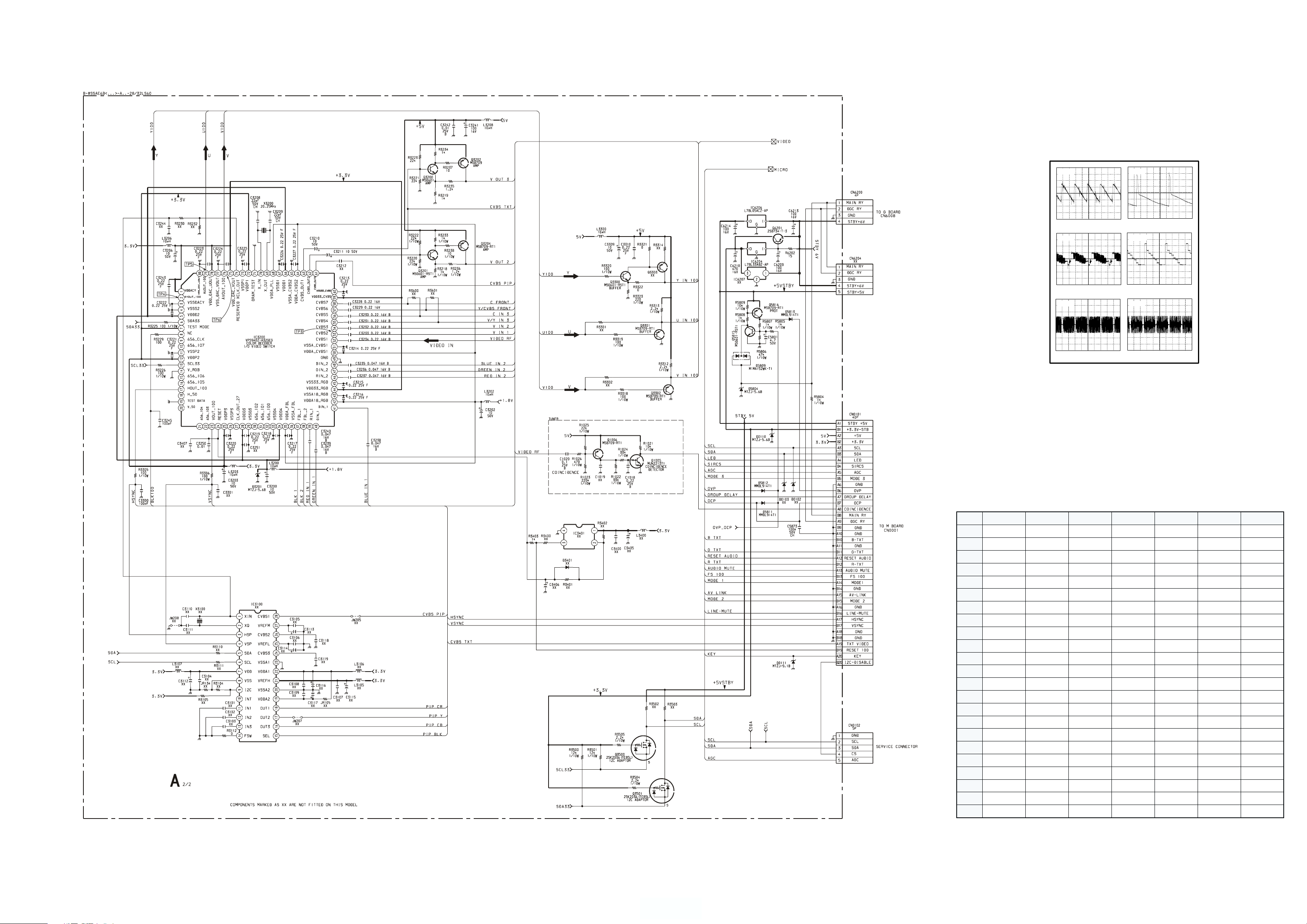
TP1 TP2
5ms/div
744 mVp-p (V) 53 Vp-p (V)
TP3
20us/div
1.4 Vp-p (H)
TP5 TP6
5ms/div
TP4
TP4
688 mVp-p (H)
264 mVp-p (H) 272 mVp-p (H)
2ms/div
10us/div
5ms/div
- 30 -
- 30 -
~ A Board Difference Table ~
~ A Schematic [ Video & Audio Processors, Audio Output,
Vertical Deflection] page 2/2~
Page 8

~ VM Printed Wiring Board Conductor side ~
~ VM Board Waveforms ~
TP1 TP2
1.54 Vp-p (H) 1.4 Vp-p (H)
5ms/div
5ms/div
TP3
20 Vp-p (H)
5ms/div
~ VM Board Voltage Table ~
feR )s()e( )g()b( )d()c(
0047Q0.57.57.8
1047Q9.05.11.4
2047Q5.51.69.8
3047Q1.55.59.8
4047Q7.41.40
5047Q1.57.40
6047Q4318.33186
7047Q1.14.186
8047Q3.66.55.2
9047Q7.53.69.0
~ A Board Location Table (A Side) ~
EDOID
1010D7-M5102D9-K7003D7-M8103D3-N1023D2-J7035D6-C9085D8-K2035CI4-B7026CI4-H
4010D4-L8102D2-M8003D7-M9103D3-N3015D6-D0045D4-E
0110D4-I9102D2-M9003D7-N1203D4-M4015D5-E4045D3-F4015CI6-D1026CI01-G2025Q2-E
1110D2-H2052D9-H1103D4-M3203D4-M0025D2-D5045D3-F0025CI3-B2026CI6-I1035Q5-C
2110D4-M1003D7-M3103D4-M4203D4-M1025D2-E7085D7-F1025CI4-C3026CI6-J6035Q4-E
3110D5-M3003D7-M5103D4-M6203D2-M5035D6-D0026D6-J0035CI4-E5026CI5-D4045Q4-F
6001D01-M
4102D9-K5003D7-M7103D4-M8203D2-M6035D5-C4007D7-F1035CI4-D6026CI3-H
CI
0045CI4-G
ROTSISNART
~ A Board Location Table (B Side) ~
EDOID
1010D7-B1003D7-B6203D2-B0045D4-K4015CI6-K0001Q6-C2023Q3-C1035Q5-L9007Q6-K
4010D5-C3003D7-B8203D2-C1045D4-J0025CI3-M1001Q6-D4023Q3-C2035Q7-K1107Q6-J
0110D4-G5003D7-B1023D2-F4045D3-J1025CI4-L4001Q01-D0033Q3-F3035Q4-M2107Q5-J
1110D2-G7003D6-B3015D6-L5045D3-I0035CI3-J5001Q2-B1033Q3-F4035Q5-M3107Q6-J
2110D5-C8003D6-B4015D5-J9085D8-K1035CI4-K6001Q3-B2033Q3-F5035Q3-K4107Q6-J
3110D5-C9003D6-B0025D2-K1185D8-L2035CI4-M0002Q9-C0053Q3-F6035Q4-K5107Q5-I
6001D01-B1103D4-C2025D4-L2185D8-L0045CI3-I2002Q9-D1053Q3-F0045Q4-J6107Q5-I
4102D9-C3103D4-C0035D5-L0026D7-F0026CI9-I3002Q9-D1015Q5-M1045Q4-K7107Q6-I
5102D9-D5103D4-C3035D4-N
6102D8-E7103D4-B4035D4-M0002CI8-C2026CI6-F5002Q7-E1025Q3-N3045Q4-J9107Q5-I
8102D2-B8103D3-B5035D6-L1002CI9-D3026CI6-E1052Q8-G2025Q3-K4045Q4-J
9102D2-B9103D3-B6035D5-L0052CI8-F5026CI5-K2052Q9-G3025Q2-J3185Q8-J
0052D9-G1203D4-C7035D7-L0013CI5-E6026CI3-G3052Q9-G4025Q4-L5185Q8-L
2052D9-G3203D3-B8035D4-M0023CI3-E7026CI4-G0023Q3-C5025Q3-M6185Q8-L
3052D9-G4203D3-B9035D3-J3015CI3-L
CI
1026CI8-I4002Q7-E0025Q4-M2045Q5-J8107Q5-I
ROTSISNART
- 33 -
1023Q2-C0035Q4-M3007Q6-H
Page 9

~ A Board Semiconductor Voltage Table ~
feR )s( )g( )d( feR )e( )b( )c( feR )e( )b( )c( feR )e( )b( )c( feR )e( )b( )c( feR )e( )b( )c(
0053Q7.23.39.32002Q004 4023Q54.44.35025Q9.12.10 3185Q09.70 5107Q6.119.018.8
1053Q7.23.34 3002Q004 0033Q7.03.15 0035Q04.02.24185Q 000 6107Q66.69.01
1035Q01.52.154002Q3.39.33.81033Q9.12.10 1035Q1.50 2.155185Q005 7107Q7.220
4045Q005.05002Q3.39.33.82033Q9.12.10 2035Q9.87.50 6185Q550 8107Q6.119.016.8
feR )e( )b( )c(
1001Q2.39.33.82052Q07.00 1053Q3.37.24 0043Q001.09007Q2.37 1.00207Q9.89.80
4001Q9.13.10 3052Q6.06.05.01015Q04.04.61045Q009.71107Q5.29.10 1207Q7.27.29.8
5001Q05.05 0023Q9.15.24.41025Q8.24.39.72045Q003.11-2107Q6.119.017.8
6001Q57.41 1023Q9.15.24.42025Q2.08.07.113045Q5.31-2.11-3.8-3107Q66.69.01
0002Q2.48.43.82023Q54.44.33025Q2.08.07.114045Q005.04107Q5.28.10
1052Q002.510053Q3.37.29.34035Q04.06.53007Q6.52.68.89107Q66.69.01
~ A Board IC Voltage Table ~
elbaTegatloVCI
oNfeR
oNniP )V(egatloV
13.1
27.17265.074.1330
36.28071.21
40 9 1.381.41-20537.4
55.2013
63.3115 2 6 4 8.4739.8
70 215 3 6 5 5.3830
80 315 4 0 6 4.3938.4
91.1410 5 6 7 6.7048.4
011.1510 6 6 8 0 148.4
110 615 7 6 9 0 240
210
310 29.4
410 38.425.8214.0543.6
0013CI
515.048.435.6319.0649.8
613.05540 415 749.8
713.06555.6515.2846
813.07561.7610 945.2
913.38574.0713 051.4
020 99.4821817.2150
123.3011.21
223.3111.428.5020 358.5
320 215 3 3.6121.6458.5
422.3315 4 0 227.2554.0
522.1419.156.6328.8658.5
622.3511.165.6420 758.5
721.2610 7 4.0523.4858.5
823.0710 8 21622.3953.0
13.3810
23.3
3015CI
39.128.335.21-929.4269.2
46.238.344.51-034.3367.3
55.244.51-54.0-136.5
oNfeR
3015CI
0025CI
1025CI
oNniP )V(egatloV
68.1
18.4821014.0340
13.922.31823.0160
oNfeR
1025CI
0035CI
1035CI
2035CI
0045CI
oNniP )V(egatloV
53.9
16 3 4.4637.4
17.1118.1440
10 919.3256
14.1722.5060
oNfeR
0045CI
2007CI
oNniP )V(egatloV
67.31
16.3437.4
oNfeR
2007CI
oNniP )V(egatloV
239.8
- 34 -
Page 10

ABCDE F
G
HI JKLMN
1
2
3
4
5
~ F2 Board Schematic Diagram [ Power Switch & Fuse. LED & IR Receiver ] ~
~ H2 Board Schematic Diagram [ Front AV & Headphone ] ~
10
6
7
8
9
11
~ VM Board Schematic Diagram [ Velocity Modulation ] ~
- 35 -
Page 11

ABCDE F
1
2
3
4
G
HI JKLMN
5
6
7
8
9
10
11
~ G Board Schematic Diagram [ Power Supply ] ~
- 37 -
Page 12

ABCDE F
1
2
3
4
G
HI JKLMN
5
6
7
8
9
10
11
~ C Board Schematic Diagram [ R-G-B Out ] ~
- 38 -
Page 13

~ C Printed Wiring Board Conductor side ~
~ M Printed Wiring Board Conductor side A ~
~ C Board Waveforms ~
~ C Board Semiconductor Voltage Table ~
feR )e( )b( )c(
0537Q2189.110
2537Q008.3
3537Q008.3
4537Q89.11210
5537Q008.3
~ C Board IC Voltage Table ~
elbaTegatloVCI
oNfeR
oNniP )V(egatloV
19.3
38.3
55.7
0037CI
6002
7041
8351
9041
19.3
38.3
57.7
5237CI
6002
7041
8351
9041
19.3
38.3
55.7
0537CI
6002
7931
8841
9831
10us/div
TP1
TP2
2.16 Vp-p (H) 2.0 Vp-p (H)
TP3
1.9 Vp-p (H)
TP5
10us/div
10us/div
TP4
TP4
6.8 Vp-p (H)
TP6
116 Vp-p (H) 100 Vp-p (H)
TP7
10us/div
100 Vp-p (H)
10us/div
10us/div
~ M Printed Wiring Board Conductor side B ~
10us/div
- 39 -
Page 14

ABCDE F
1
2
3
4
G
HI JKLMN
5
6
7
8
9
10
11
~ M Board Schematic Diagram [ Micro• Processor ] ~
- 40 -
Page 15

ABCDE F
1
2
3
4
G
HI JKLMN
5
6
7
8
9
10
11
~ D Board Schematic Diagram [ Deflection ] ~
- 42 -
Page 16

~ D Board Difference Table ~
feR B06SL82 E06SL82 U06SL82 B06SL23 E06SL23 K06SL23 U06SL23
7018C--- W01/1%5.0K72W01/1%5.0K72W01/1%5.0K72W01/1%5.0K72
0318CV05%5FP022V05%5FP022V05%5FP022____
7028C___ V61%01FU740.0V61%01FU740.0V61%01FU740.0V61%01FU740.0
8028C___ V52%01FU10.0V52%01FU10.0V52%01FU10.0V52%01FU10.0
4188CVK2.1%3FP0057VK2.1%3FP0057VK2.1%3FP0057VK2.1%3FP0086VK2.1%3FP0086VK2.1%3FP0086VK2.1%3FP0086
5188CVK5.1%3FP0086VK5.1%3FP0086VK5.1%3FP0086VK5.1%3FP0026VK5.1%3FP0026VK5.1%3FP0026VK5.1%3FP0026
5288CV052%5FU22.0V052%5FU22.0V052%5FU22.0V052%5FU81.0V052%5FU81.0V052%5FU81.0V052%5FU81.0
6288CV052%5FU86.0V052%5FU86.0V052%5FU86.0V052%5FU65.0V052%5FU65.0V052%5FU65.0V052%5FU65.0
7218RW01/1%5.0K7.4W01/1%5.0K7.4W01/1%5.0K7.4W01/1%5.0K8.6W01/1%5.0K8.6W01/1%5.0K8.6W01/1%5.0K8.6
1418RW01/1%5.0K22W01/1%5.0K22W01/1%5.0K22W01/1%5.0K33W01/1%5.0K33W01/1%5.0K33W01/1%5.0K33
2418RW01/1%5.0K5.7W01/1%5.0K5.7W01/1%5.0K5.7W01/1%5.0K7.4W01/1%5.0K7.4W01/1%5.0K7.4W01/1%5.0K7.4
4418RW01/1%5K022W01/1%5K022W01/1%5K022W01/1%5K021W01/1%5K021W01/1%5K021W01/1%5K021
9418RW01/1%5K22W01/1%5K022W01/1%5K022W01/1%5K9.3W01/1%5K9.3W01/1%5K9.3W01/1%5K9.3
0518RW01/1%5K22W01/1%5K22W01/1%5K22W01/1%5K8.6W01/1%5K8.6W01/1%5K8.6W01/1%5K8.6
4518RW01/1%5K6.5W01/1%5K6.5W01/1%5K6.5W01/1%5K3.3W01/1%5K3.3W01/1%5K3.3W01/1%5K3.3
5518RW01/1%5.0K7.4W01/1%5.0K7.4W01/1%5.0K7.4W01/1%5K7.2W01/1%5K7.2W01/1%5K7.2W01/1%5K7.2
8518RW01/1%5.0K2.2W01/1%5.0K2.2W01/1%5.0K2.2W01/1%5.0K7.4W01/1%5.0K7.4W01/1%5.0K7.4W01/1%5.0K7.4
9518RW01/1%5.0K2.2W01/1%5.0K2.2W01/1%5.0K2.20TROHS0TROHS0TROHS0TROHS
1618RW01/1%5.0K8.6W01/1%5.0K8.6W01/1%5.0K8.6W01/1%5.0K2.8W01/1%5.0K2.8W01/1%5.0K2.8W01/1%5.0K2.8
5718RW01/1%5K7.4W01/1%5K7.4W01/1%5K7.4W01/1%5K8.6W01/1%5K8.6W01/1%5K8.6W01/1%5K8.6
6718R0TROHS0TROHS0TROHSW01/1%5K01W01/1%5K01W01/1%5K01W01/1%5K01
7718RW01/1%5K6.5W01/1%5K6.5W01/1%5K6.5W01/1%5K7.4W01/1%5K7.4W01/1%5K7.4W01/1%5K7.4
9718RW01/1%5K7.4W01/1%5K7.4W01/1%5K7.40TROHS0TROHS0TROHS0TROHS
6818RW01/1%5K7.2W01/1%5K7.2W01/1%5K7.2W01/1%5K9.3W01/1%5K9.3W01/1%5K9.3W01/1%5K9.3
9818RW01/1%5K5.1W01/1%5K5.1W01/1%5K5.1W01/1%5065W01/1%5065W01/1%5065W01/1%5065
3028RW01/1%5K8.6W01/1%5K8.6W01/1%5K8.60TROHS0TROHS0TROHS0TROHS
6028RW01/1%5K074W01/1%5K074W01/1%5K074W01/1%5.0K033W01/1%5.0K033W01/1%5.0K033W01/1%5.0K033
7028RW01/1%5K072W01/1%5K072W01/1%5K072W01/1%5K022W01/1%5K022W01/1%5K022W01/1%5K022
5128RW01/1%5.0K22W01/1%5.0K22W01/1%5.0K22W01/1%5.0K74W01/1%5.0K74W01/1%5.0K74W01/1%5.0K74
6128RW01/1%5K74W01/1%5K74W01/1%5K74W01/1%5.0K74W01/1%5.0K74W01/1%5.0K74W01/1%5.0K74
0228RW01/1%5K8.6W01/1%5K8.6W01/1%5K8.6W01/1%5K21W01/1%5K21W01/1%5K21W01/1%5K21
1228RW01/1%5K81W01/1%5K81W01/1%5K81W01/1%5K22W01/1%5K22W01/1%5K22W01/1%5K22
4228R___ W01/1%5K3.3W01/1%5K3.3W01/1%5K3.3W01/1%5K3.3
0188RW2%5K7.4W2%5K7.4W2%5K7.4W2%5K9.3W2%5K9.3W2%5K9.3W2%5K9.3
6388RW4/1%5K81W4/1%5K81W4/1%5K81W4/1%5K51W4/1%5K51W4/1%5K51W4/1%5K51
6588RW3%5K2.8W3%5K2.8W3%5K2.8W3%5K8.6W3%5K8.6W3%5K8.6W3%5K8.6
7588RW3%5K2.8W3%5K2.8W3%5K2.8W3%5K8.6W3%5K8.6W3%5K8.6W3%5K8.6
8588RW3%5K2.8W3%5K2.8W3%5K2.8W3%5K8.6W3%5K8.6W3%5K8.6W3%5K8.6
9588RW3%5K2.8W3%5K2.8W3%5K2.8W3%5K8.6W3%5K8.6W3%5K8.6W3%5K8.6
6888RW01/1%5.0K022W01/1%5.0K022W01/1%5.0K022W01/1%5K022W01/1%5K022W01/1%5K022W01/1%5K022
7988RW4/1%1K074W4/1%1K074W4/1%1K074W4/1%1K086W4/1%1K086W4/1%1K086W4/1%1K086
0088TYSSATBF
412Z//2254XN
YSSATBF
412Z//2254XN
YSSATBF
412Z//2254XN
YSSATBF
4B2Z//2254XN
YSSATBF
4B2Z//2254XN
YSSATBF
4B2Z//2254XN
YSSATBF
4B2Z//2254XN
- 43 -
Page 17

5-4. SEMICONDUCTORS
1
16
17
32
1
14 15
28
CXAB070AP
MCZ3001D
18
1
CXA1875AM-T4
16 9
1
( TOP VIEW )
LM318P
PST573IMT
LM358N
LM393DT
10
LM393N
M24C16-MN6T(A)
7
6
8
5
9
2
3
1
LM78L05ACZ
8
4
SAA5665HL/M1D/0358
IN
OUT
GND
25
123
+
100
1
26 50
1
Vcc
Out
3
2
Gnd
76
75
51
CXA2100AQ-TL
51
52
64
1
(TOP VIEW)
K6T2008V2A-YF70T00
MSP3411G-QA-B10
33
32
20
19
9
10
18
26
68
1
( TOP VIEW )
61
60
52
44
433527
SBX3081-51(30)
SDA9488X-B23GEG
NJM3404AD-W
UPC4558G2
85
1
4
( TOP VIEW )
LA6500-FA
PQ30RV11
1 : V IN
2 : V OUT
3 : GND
4 : ON/OFF CONTROL
STV9379
1
2
3
4
1
7
- 44 -
Page 18

TCET1103G
115
1
2
3
TDA6111Q/N4
DTA144EK
DTC144TKA-T146
2SA1162-G
C
E
B
DTA144ESA
2SA933AS-QT
2SC2785-HFE
SE135N-LF4
2
1
2SA1837(LBS2S0N)
3
1V
OUT
2 COLLECTOR
3 GND
SENSE
19
TDA7497
VPS9402-A32GEG
1
6180
60
B
C
E
L7809CV/LSY
STP5NB40FP
STP5NB40(030Y)
2SC5698-CA
2S5696-SONY-CA
MSB709-RT1
MSD601-RST1
M1MA152WA-T1
UN2111
UN213
2SK2036(TE85L)
B
C
2SB734-34
2SC2688(5)-LK
E
20
21
(TOP VIEW)
BA12T
BAO33T
IRF614-005
IRF620
SPA07N60C2
2SA2005
2SC5511
B
E
C
41
40
RB705D
3
2
E
BAS216
1
2
3
1
B
C
- 45 -
Page 19

BAS316-115
MMDL914T1
UDZSTE-176.2B
ANODE
CATHODE
BYV98-200-RAS 15/12
CATHODE
ANODE
D1NL20U
EGP20G
EL1Z
GP08D
UF4005PKG23
FBIU4D7MA-B
RBV-406B
S1VB40
GS1B460/45
D2S4MTA1
ERA38-06
ERA85-009
HZS9.1NB2
MTZJ-13B
MTZJ-33B
MTZJ-3.6A
MTZJ-4.7C
CATHODE
ANODE
MTZJ-T-77-22
RD15ES-B2
RD39ES-B2
RD5.6ESB2
1SS119-25
1SS133T-77
TLHK5190
ANODE
CATHODE
CATHODE
ANODE
- 46 -
Page 20

5-5 IC BLOCK DIAGRAMS
A BOARD IC6202/IC6205 BA033T/BA12T
1
REFERENCE
VOLTAGE
2
A BOARD IC2500 TDA7497
VOLUME
1
30K
VOLUME
5
30K
-
+
2
MUTE/STBY
PROTECTIONS
3
14
OP AMP
9
10
60K
12
OP AMP
G BOARD IC6001 MCZ3001D
Remote
1
Vsense
5
SS
DVLD
15v/8v
7
4 3 2
Osc
Internal
ref 5v
F/B
43
18
Latch
Centre
OFF
Sel=34v
Timer
8
Driver
Reg. 10v
TSD
Level
Shift
Control
Logic
OCP
6
14
16
15
10
12
11
9
- 47 -
Page 21

A BOARD IC2000 MSP3411G
65 68 13 45 7 6
25
23
28
31
30
34
33
37
36
SBUS Interface
DEMODULATOR
IDENT
DFP
A/D
A/D
SCART Switching Facilities
I2C Interface
D/A
D/A
D/A
D/A
D/A
D/A
56
57
59
60
47
48
50
51
G BOARD IC6003 SE135N-LF4
A BOARD IC5400 STV9379
2 6 3
1
7
-
POWER
AMPLIFIER
+
8 7 269
FLYBACK
GENERATOR
THERMAL
PROTECTION
A BOARD IC5301/IC5302 LM393N
15 4 3
1
-
+
2
3
A BOARD IC5300 LM358N
1
2
++
--
3
5
4
7
-
+
6
5
8
7
6
5
4
- 48 -
Page 22

NOTE :
SECTION 6
EXPLODED VIEWS
Items with no part number and no description are not
stocked because they are seldom required for routine
service.
The construction parts of an assembled part are indicated
with a collation number in the remarks column.
6-1. CHASSIS
17
18
19
15
16
16
Items marked “*” are not stocked
since they are seldom required for
routine service. Some delay should
be anticipated when ordering these
items.
13
15
14
2
3
12
4
21
11
10
9
8
7
5
6
20
UK Models
only
1
REF.NO. PART.NO DESCRIPTION REMARK REF.NO. PART.NO DESCRIPTION REMARK
1 *A-1647-043-A H2 BOARD, COMPLETE
2 *A-1624-102-A F2 BOARD, COMPLETE
3 *4-206-055-01 BRACKET F2
4 £ 1-571-433-21 SWITCH, PUSH (AC POWER)
5 *4-202-531-01 AC CORD LOCK (SC)
6 £ 1-823-853-11 CORD, POWER (KV-28LS60B/28LS60E/32LS60B/
KV-32LS60E/32LS60K)
£ 1-776-860-12 POWER CORD, FILTER (UK)
(KV-28LS60U/32LS60U)
7 1-424-855-11 COIL, CHOKE 29MMH
8 *4-206-106-01 BRACKET, MAIN
9 *A-1300-179-A G BOARD, COMPLETE
10 8-598-535-11 FRONTEND BTF-EF411 (KV-28LS60B/32LS60B)
8-598-533-01 FRONTEND BTF-EC411 (KV-28LS60E/32LS60E
/32LS60K)
8-598-529-01 FRONTEND BTF-EU611 (KV-28LS60U/32LS60U)
11 *A-1300-287-A M BOARD, COMPLETE
12 *A-1300-302-A A BOARD, COMPLETE (KV-28LS60B)
*A-1300-301-A A BOARD, COMPLETE (KV-28LS60U)
*A-1300-288-A A BOARD, COMPLETE (KV-32LS60B)
*A-1300-177-A A BOARD, COMPLETE (KV-32LS60E/32LS60K)
*A-1300-289-A A BOARD, COMPLETE (KV-32LS60U)
13 £ 1-453-383-21 TRANSFORMER ASSY, FLYBACK (NX-4522//Z214)
(KV-28LS60)
£ 1-453-340-31 TRANSFORMER ASSY, FLYBACK (NX-4522//Z2B4)
(KV-32LS60)
14 *A-1300-176-A D BOARD, COMPLETE (KV-28LS60)
*A-1300-178-A D BOARD, COMPLETE (KV-32LS60)
15 7-685-663-71 SCREW +BVTP 4x16 TYPE 2 IT-3
16 1-529-408-11 SPEAKER (4.2x24CM)
17 *A-1678-219-A WOOFER COMPL. ASSY 18-19
18 7-685-663-71 SCREW +BVTP 4x16 TYPE 2 IT-3
19 1-529-989-11 SPEAKER (8CM)
20 4-206-089-11 COVER REAR (KV-28LS60)
4-206-062-21 COVER REAR (KV-32LS60)
21 7-685-663-79 SCREW +BVTP 4x16 TYPE 2 IT-3
*A-1300-175-A A BOARD, COMPLETE (KV-28LS60E)
- 49 -
Page 23

6-2. PICTURE TUBE
73
67
74
75
76
77
55
54
72
71
70
58
69
68
59
60
66
61
62
63
66
65
64
52
51
53
56
57
REF.NO. PART.NO DESCRIPTION REMARK REF.NO. PART.NO DESCRIPTION REMARK
51 X-4039-915-1 BEZNET ASSY (KV-28LS60) 52-55
X-4200-824-1 BEZNET ASSY (KV-32LS60)
52 4-205-948-02 POWER BUTTON
53 4-204-426-01 SPRING
54 4-205-375-01 GUIDE, LIGHT
55 4-204-295-01 SHEET, BLOTTING
56 X-4200-712-3 DOOR ASSY (KV-28LS60) 57-58
X-4039-993-1 DOOR ASSY (KV-32LS60)
57 4-205-946-02 DOOR
58 4-047-464-01 CATCHER, PUSH
59 £ 8-451-521-11 DEFLECTION YOKE (Y28RVC3-B)(KV-28LS60)
£ 1-451-480-11 DEFLECTION YOKE (Y32RVC2)(KV-32LS60)
60 1-419-363-11 COIL, NA ROTATION (RT200)
61 8-453-011-11 NECK ASSY, (NA299-M)
62 *A-1644-119-A VM BOARD, COMPLETE
63 *A-1638-158-A C BOARD, COMPLETE
65 £ 1-424-886-11 COIL, DEGAUSSING (KV-28LS60)
£ 1-424-888-11 COIL, DEGAUSSING (KV-32LS60)
66 4-203-390-11 CUSHION, DGC
67 *4-204-768-01 HOLDER, DGC (29”)
68 *4-203-022-01 HOLDER, HV
69 £ 1-251-946-21 CAP ASSY, HIGH-VOLTAGE (KV-28LS60)
£ 1-251-374-32 CAP ASSY, HIGH-VOLTAGE (KV-32LS60)
70 3-704-495-01 SPACER, DY
71 £ 8-735-099-05 PICTURE TUBE (W66LLX060X)(KV-28LS60)
£ 8-735-079-05 PICTURE TUBE (W76LLZ060X)(KV-32LS60)
72 4-046-765-12 SCREW, TAPPING 7+CROWN WASHER
73 4-308-870-00 CLIP, LEAD WIRE
74 1-452-094-00 MAGNET, ROTATABLE DISK; 15MM
75 1-452-032-00 MAGNET, DISK; 10MM
76 X-4387-214-1 PERMALLOY ASSY, CORRECTION
77 3-701-007-00 BAND, BINDING
64 4-369-318-21 SPRING, TENSION
- 50 -
 Loading...