

SONY AA-2W Service Manual

SERVICE MANUAL
MODEL NAME REMOTE COMMANDER DESTINATION CHASSIS NO.
AA-2W
CHASSIS
KV-29FV16A
RM-Y171 Argentina SCC-S34P-A
9-965-908-01
KV-29FV16A
RM-Y171
TRINITRON® COLOR TELEVISION
SECTION 4: CIRCUIT ADJUSTMENTS
ELECTRICAL ADJUSTMENTS BY REMOTE COMMANDER
Use the Remote Commander (RM-Y171) to perform the circuit adjustments in this section.
Test Equipment Required: 1. Pattern generator 2. Frequency counter 3. Digital multimeter 4. Audio oscillator
KV-29FV16A
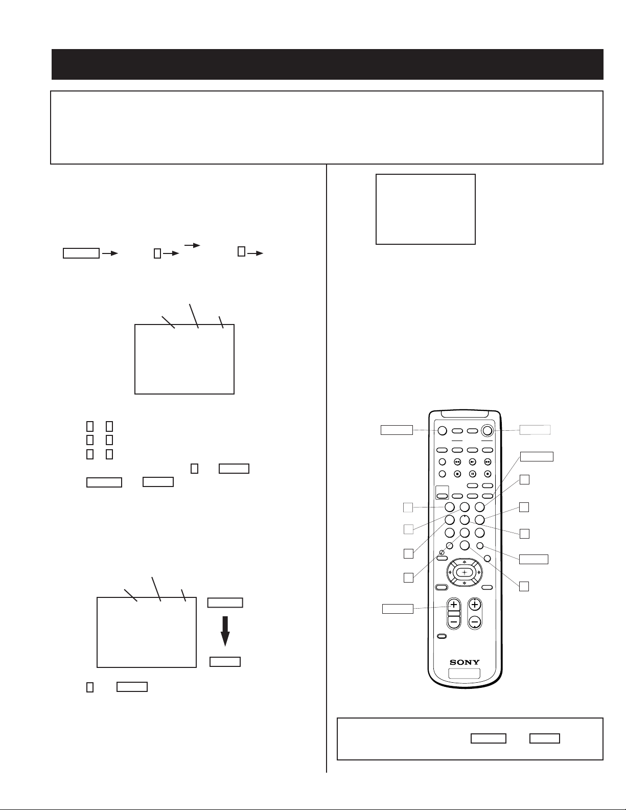
4-1. SETTING THE SERVICE ADJUSTMENT
MODE
1. Standby mode (Power off).
2. Press the following buttons on the remote commander within a
second of each other:
DISPLAY
Channel 5 Sound Volume
+
Power
SERVICE ADJUSTMENT MODE IN
Register Item
Device Item Data Item
SERVICE VP VPOS 30
1000 0
3. The CRT displays the item being adjusted.
4. Press 2 or 5 on the Remote Commander to select the device item.
5. Press
6. Press
7. To recover the latest values, press
8. Press
1
or 4 on the Remote Commander to select the item.
3
or 6 on the Remote Commander to change the data.
0
ENTER
MUTING
then
then
ENTER
to write into memory**.
.
Note: If the NVM is replaced, perform this test and reset. Then
download from microprocessor to NVM to prevent loss of
picture.
SERVICE ADJUSTMENT MODE MEMORY
Register Item
Device Item Data Item
SERVICE VP VPOS 30
1000 0
MUTING
Green
SERVICE WRITE
1000 0000
Factory original setting
10. Turn set off and on to exit.
4-2. MEMORY WRITE CONFIRMATION
METHOD
1. After adjustment, pull out the plug from the AC outlet, then replace the
plug in the AC outlet again.
2. Turn the power switch ON and set to Service Mode.
3. Call the adjusted items again to confi rm they were adjusted.
4-3. REMOTE ADJUSTMENT BUTTONS AND
INDICATORS
FREEZE
SLEEP
SAT/CABLE
FUNCTION
SAT/CABLE
SWAP PIP
AUDIO
CHVOL
ENTER
POWER
TV/VIDEO
TV/VIDEOANT
DISPLAYMTS/SAP
RM-Y171
GUIDE
TV
TV
POWER
(Service mode)
DISPLAY
(Service mode)
3
(Data up)
6
(Data down)
5
(Device item down)
ENTER
(Write into memory)
0
(Read out of memory)
(Write into memory)
MUTING
1
(Item up)
2
(Device item up)
4
(Item down)
8
(Initialize)
VOL (+)
(Service mode)
MUTING
VTR/DVD
SYSTEM
VTR/DVD
OFF
TV/VTR
+
CH
POSITION
Ð
PICTURE
MODE
1 2 3
4 5 6
7 809
JUMP
TV/SAT
RESET MENU
CODE SET
Red
9. Press
then
8
ENTER
ENTER
on the Remote Commander to initialize.
Note: Carry out this step when adjusting IDs 0 to 4 and when
replacing IC102.
— 13 —
TV
RM-Y171
** WARNING: Do NOT turn off the power or remove the AC cord
immediately after pressing
MUTING
then
ENTER
. Wait at
least 10 seconds
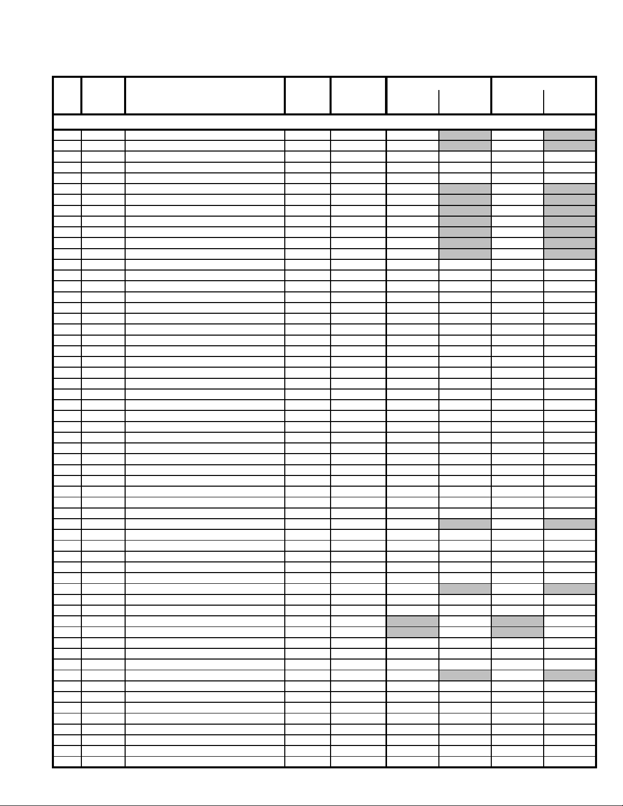
SERVICE DATA
V
V
KV-29FV16A
No. Initial Data Average Data
Name
DescriptionRegister
Range
Adj/FixData
NTSC
PAL-M
PAL-N
TV/AUX
S/VIDEO 1-3
VIDEO 4
NTSC
PAL-M
PAL-N
TV/AUX
S/VIDEO 1-3
VIDEO 4
P CXA2135S
1 HPOS Horizontal Position Adjust 0-31 Fix 7 7
2 HSIZ Horizontal Amp Adjust 0-31 Fix 10 10
3 VBOW VRT Line Bowing Adjust 0-15 Fix6666
4 VANG VRT Line Bow Slant Adjust 0-15 Fix5555
5 TRAP Horizontal Trapezoid Adjust 0-15 Fix6666
6 PAMP Horizontal Pin Distort Adjust 0-63 Fix 32 32
7 UCPN Upper Pin 0-63 Fix 36 36
8 LCPN Lower Pin 0-63 Fix 36 36
9 VSIZ Vertical Amplitude Test 0-63 Fix 0 0
10 VPOS Vertical Position Test 0-63 Fix 31 31
11 VLIN Vertical Linearity Adjust 0-15 Fix 7 7
12 VSCO S-Correction 0-15 Fix 7 7
13 VZOM 16:9 CRT Z Mode On/Off 0,1 Fix0000
14 EHT VRT High Volt Correction 0-15 Fix4444
15 ASP Aspect Ratio Control 0-63 Fix47474747
16 SCRL 16:9 CRT Z Mode Tran Scroll 0-63 Fix31313131
17 HBSW HBLK SW 0,1 Fix1111
18 LBLK Left Screen H Blk Control 0-15 Fix15151515
19 RBLK Right Screen H Blk Control 0-15 Fix0000
20 HDW H Drive Pulse Width 0,1 Fix0011
21 EWDC EW/DC Adjust 0,1 Fix0000
22 LVLN Screen Bottom VRT Lin Adjust 0-15 Fix0000
23 UVLN Screen Top VRT Lin Adjust 0-15 Fix0000
24 RDRV R Output Drive Control 0-63 Adj 31 31 31 31
25 GDRV G Output Drive Control 0-63 Adj 31 31 31 31
26 BDRV B Output Drive Control 0-63 Adj 31 31 31 31
27 RCUT R Output Cutoff Control 0-15 Adj 7777
28 GCUT G Output Cutoff Control 0-15 Adj 7777
29 BCUT B Output Cutoff Control 0-15 Adj 7777
30 RDR4 Video 4 R Output Drive Control 0-63 Adj 31 31 31 31
31 GDR4 Video 4 G Output Drive Control 0-63 Adj 31 31 31 31
32 BDR4 Video 4 B Output Drive Control 0-63 Adj 31 31 31 31
33 RCU4 Video 4 R Output Cutoff Control 0-15 Adj 7777
34 GCU4 Video 4 G Output Cutoff Control 0-15 Adj 7777
35 BCU4 Video 4 B Output Cutoff Control 0-15 Adj 7777
36 SHUE Sub Hue 0-31 Adj 7 7 15 15
37 SCOL Sub Color 0-31 Adj 15 15
38 SBRT Sub Brightness 0-63 Fix15151515
39 RON R Output On/Off 0,1 Fix1111
40 GON G Output On/Off 0,1 Fix1111
41 BON B Output On/Off 0,1 Fix1111
42 AXPL Axis Pal 0,1 Fix0000
43 CBPF Chroma BPF On/Off 0,1 Fix 1 1
44 COFF Color On/Off 0,1 Fix0000
45 KOFF Set Color Killer 0,1 Fix0000
46 SSHP Sub Sharpness 0-15 Fix 7 7
47 SHPF Sharpness Circuit F0 0,1 Fix 1 1
48 PREL Pre/Over-Shoot Switching 0,1 Fix1111
49 Y-DC DC Trans Radio Switching 0,1 Fix1111
50 ABLM ABL Mode Switching 0,1 Fix1111
51 YDEL Y Delay Time Control 0-15 Fix 7 7
52 NCOL No Color ID 0,1 Fix1111
53 FSC FSC Out On/Off 0,1 Fix1111
54 K-ID Killer ID 0,1 Fix1111
55 HOSC H VCO Oscillation Frequency 0-15 Fix7777
56 VSS V Sync Slice Level 0,1 Fix0011
57 HSS H Sync Slice Level 0,1 Fix0011
58 HMSK H Mask 0,1 Fix1111
59
TMS Select Signal VTIM Pin 0-3 Fix0000
— 14 —
 Loading...