

Sony 40EX700, 52EX701, 32EX700, 46EX700, 46EX701 User Manual
...
SERVICE MANUAL
HISTORY INFORMATION FOR THE FOLLOWING MANUAL:
SERVICE MANUAL
AZ1-L Chassis
ORIGINAL MANUAL ISSUE DATE: 1/2010
Version Date Subject
1.0 1/25/2010 No revisions or updates
2.0 1/29/2010 Corrected part information for Lens. Replaced pages i, 16-18.
3.0 3/17/2010 Corrected Disassembly/Part Number Information section. Replaced pages 12-20.
Corrected Service Adjustment Information. Reissue entire manual.
LCD Digital Color TV
9-888-268-03
SERVICE MANUAL
SERVICE MANUAL
AZ1-L Chassis
Self Diagnosis
Supported model
LCD Digital Color TV
9-888-268-03
MODEL LIST
MODEL COMMANDER DESTINATION MODEL COMMANDER DESTINATION
KDL-32EX700 RM-YD033 US
KDL-52EX700 RM-YD033 US
KDL-32EX700 RM-YD055 CND/MX
KDL-40EX700 RM-YD033 US
KDL-40EX700 RM-YD055 CND/MX
KDL-40EX703 RM-YD055 CND
KDL-46EX700 RM-YD033 US
KDL-46EX700 RM-YD055 CND/MX
KDL-46EX701 RM-YD033 US
KDL-46EX701 RM-YD055 CND
KDL-46EX703 RM-YD055 CND
KDL-52EX700 RM-YD055 CND/MX
KDL-52EX701 RM-YD033 US
KDL-52EX701 RM-YD055 CND
KDL-52EX703 RM-YD055 CND
KDL-60EX700 RM-YD033 US
KDL-60EX700 RM-YD055 CND/MX
KDL-60EX701 RM-YD033 US
KDL-60EX701 RM-YD055 CND
KDL-60EX703 RM-YD055 CND
9-888-268-03

TABLE OF CONTENTS
Specifi cations..................................................................................................................................................................................1
Warnings and Cautions ..................................................................................................................................................................3
Safety-Related Warning ..................................................................................................................................................................5
Safety Check-Out ............................................................................................................................................................................6
Self Diagnosis Functions ...............................................................................................................................................................8
SEC 1. Disassembly/Part Number Information ..........................................................................................................................12
1-1. Table-Top Stand Assembly Removal .............................................................................................................................12
1-2. Rear Cover, Switch Unit, and Power Switch Removal ..................................................................................................13
1-2-1. KDL-32EX700 and KDL-40EX700/40EX703 ............................................................................................................................. 13
1-2-2. KDL-46EX700/46EX701/46EX703 and KDL-52EX700/52EX701/52EX703 .............................................................................. 14
1-2-3. KDL-60EX700/60EX701/60EX703 ............................................................................................................................................ 14
1-3. Speakers, HLR Board, and LCD Panel Brackets Removal ...........................................................................................15
1-4. GE3-A/GE2-A/GE2-B (Power) Boards, BAL Board, HMS2 Board, and LCD Panel Removal .......................................16
1-4-1. KDL-32EX700/40EX700/40EX703 ............................................................................................................................................ 16
1-4-2. KDL-46EX700/46EX701/46EX703 ............................................................................................................................................ 17
1-4-3. KDL-52EX700/52EX701/52EX703 ............................................................................................................................................ 17
1-4-4. KDL-60EX700/60EX701/60EX703 ............................................................................................................................................ 18
1-5. Cleaning the LCD Panel ...............................................................................................................................................18
1-6. Screw Legend................................................................................................................................................................18
1-6-1. KDL-32EX700 ............................................................................................................................................................................ 18
1-6-2. KDL-40EX700/40EX703 ............................................................................................................................................................ 18
1-6-3. KDL-46EX700/46EX701/46EX703 ............................................................................................................................................ 18
1-6-4. KDL-52EX700/52EX701/52EX703 ............................................................................................................................................ 18
1-6-5. KDL-60EX700/60EX701/60EX703 ............................................................................................................................................ 18
KDL-32EX700/40EX700/40EX703/46EX700/46EX701/46EX703/ i
52EX700/52EX701/52EX703/60EX700/60EX701/60EX703

TABLE OF CONTENTS
1-7. Connectors ....................................................................................................................................................................19
1-7-1. KDL-32EX700 ............................................................................................................................................................................ 19
1-7-2. KDL-40EX700/40EX703 ............................................................................................................................................................ 19
1-7-3. KDL-46EX700/46EX701/46EX703 ............................................................................................................................................ 20
1-7-4. KDL-52EX700/52EX701/52EX703 ............................................................................................................................................ 20
1-7-5. KDL-60EX700/60EX701/60EX703 ............................................................................................................................................ 20
1-8. Accessories and Packaging ..........................................................................................................................................21
1-9. Miscellaneous ................................................................................................................................................................21
1-10. Remote Commander .....................................................................................................................................................21
SEC 2. Service Adjustments ........................................................................................................................................................22
2-1. Accessing Service Adjustment Mode ............................................................................................................................22
2-1-1. Viewing the Service Menus ........................................................................................................................................................ 23
2-1-2. Using the Remote Commander to View or Change Service Data ............................................................................................. 23
2-2. Adjustments After Replacing the BAL Board or LCD Panel ..........................................................................................24
2-2-1. Updating the Software ............................................................................................................................................................... 24
2-2-2. Selecting the Model ................................................................................................................................................................... 24
2-2-3. Setting the Destination ............................................................................................................................................................... 25
2-2-4. Verifying the Model and Panel Information ................................................................................................................................ 26
2-2-5. Reconnecting All Cables ............................................................................................................................................................ 27
2-3. White Balance Adjustments ...........................................................................................................................................28
2-4. Resetting the TV to Factory Condition ...........................................................................................................................29
2-4-1. Resetting the TV to Factory Condition Using Service Mode ...................................................................................................... 29
KDL-32EX700/40EX700/40EX703/46EX700/46EX701/46EX703/ ii
52EX700/52EX701/52EX703/60EX700/60EX701/60EX703

TABLE OF CONTENTS
SEC 3. Diagrams ...........................................................................................................................................................................30
3-1. Circuit Boards Location .................................................................................................................................................30
3-1-1. KDL-32EX700 ............................................................................................................................................................................ 30
3-1-2. KDL-40EX700/40EX703 ............................................................................................................................................................ 31
3-1-3. KDL-46EX700/46EX701/46EX703 ............................................................................................................................................ 32
3-1-4. KDL-52EX700/52EX701/52EX703 ............................................................................................................................................ 33
3-1-5. KDL-60EX700/60EX701/60EX703 ............................................................................................................................................ 34
3-2. Block Diagram ...............................................................................................................................................................35
KDL-32EX700/40EX700/40EX703/46EX700/46EX701/46EX703/ iii
52EX700/52EX701/52EX703/60EX700/60EX701/60EX703
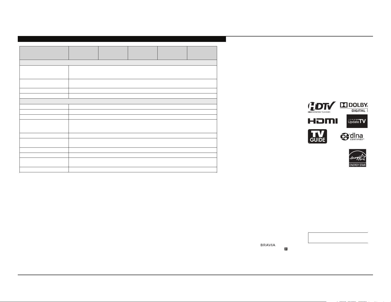
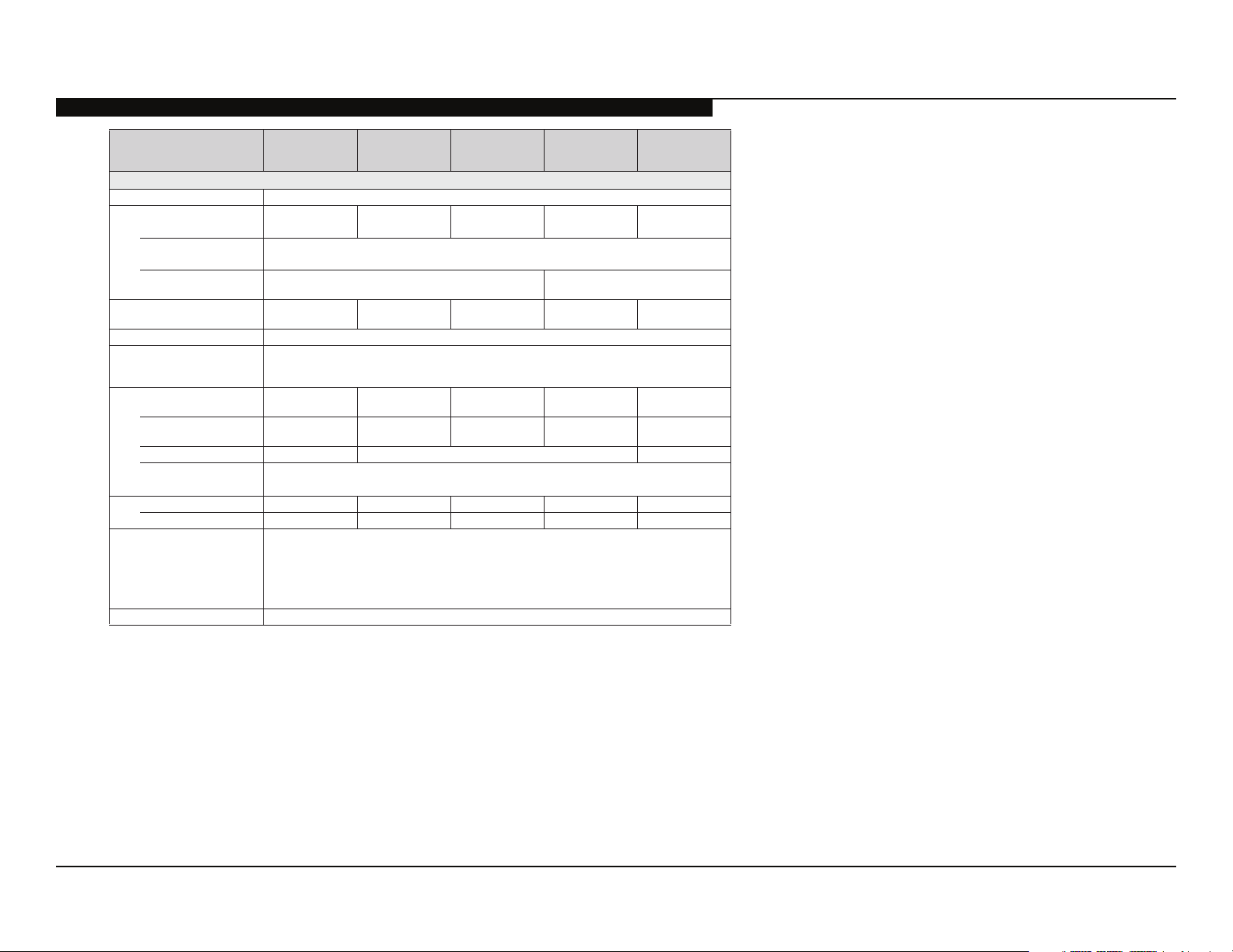
SPECIFICATIONS
p
a
s
Model name KDL- 60EX703
60EX701
60EX700
52EX703
52EX701
52EX700
46EX703
46EX701
46EX700
40EX703
40EX700
System
Television system NTSC: American TV standard
Channel coverage Analog terrestrial: 2 - 69 / Digital terrestrial: 2 - 69
Panel system LCD (Liquid Crystal Display) Panel
Speaker output 10 W + 10 W
ATSC (8VSB terrestrial): ATSC compliant 8VSB
QAM on cable: ANSI/SCTE 07 2000 (Does not include CableCARD functionality)
Analog Cable: 1 - 135 / Digital Cable: 1 - 135
Input/Output jacks
CABLE/ANTENNA 75-ohm external terminal for RF inputs
VIDEO IN 1/2 VIDEO / AUDIO
COMPONENT IN 1/2 YPBPR (Component Video) / Signal format: 480i, 480p, 720p, 1080i, 1080p / AUDIO
HDMI IN 1/2/3/4 HDMI: Video: 480i, 480p, 720p, 1080i, 1080p, 1080/24p
AUDIO OUT 500 mVrms (typical)
DIGITAL AUDIO OUT
(OPTICAL)
PC/HDMI 4 AUDIO IN Stereo mini jack
LAN
USB/DLNA Refer to the i-Manual for supported format.
*1 For LAN connections, use a Category 7 10BASE-T/100BASE-TX cable (not supplied).
HDMI: Audio: Two channel linear PCM 32, 44.1 and 48 kHz, 16, 20 and 24 bits, Dolby Digital
AUDIO (HDMI IN 4)
PCM/Dolby Digital optical signal
BGR golana ,nip-51 bus-DNI CP
10BASE-T/100BASE-TX connector (Connection speed may differ depending on the network environment.
10BASE-T/100BASE-TX communication rate and communication quality are not guaranteed for this TV.)*
32EX700
Licensing Information
Macintosh is a trademark of Apple Inc.,
registered in the U.S. and other countries.
HDMI, the HDMI logo and High-Definition
Multimedia Interface are trademarks or
registered trademarks of HDMI Licensing,
LLC.
Fergason Patent Properties, LLC:
U.S. Patent No. 5,717,422
U.S. Patent No. 6,816,141
Manufactured under license from Dolby
Laboratories. Dolby and the double-D
symbol are trademarks of Dolby
Laboratories.
In the United States, TV Guide and TV Guide
On Screen are registered trademarks of TV
Guide Entertainment Group, Inc. and/or its
subsidiaries or affiliates, and are used under a
license by Gemstar-TV Guide International,
Inc. and/or its subsidiaries. In Canada, TV
Guide is a registered mark of
Transcontinental Inc., and is used under a
license by Gemstar-TV Guide International,
Inc. and/or its subsidiaries.
The TV Guide On Screen system is
manufactured under license from Gemstar-
1
TV Guide International, Inc. and/or its
subsidiaries.
The TV Guide On Screen system is protected
by one or more of t he following United States
patents 6,498,895; 6,850,693; 6,396,546;
5,940,073; 6,239,794 to Gemstar-TV Guide
International, Inc. and/or its subsidiaries.
Gemstar-TV Guide International, Inc. and/or
its related affiliates are not in any way liable
for the accuracy or availability of the program
schedule information or other data in the TV
Guide On Screen system and cannot
guarantee service availability in your area. In
no event shall Gemstar-TV Guide
International, Inc. and/or its related affiliates
be liable for any damages in connection with
the accuracy or availability of the program
schedule information or other data in the TV
Guide On Screen system.
Blu-ray Disc is a trademark.
“BRAVIA” and , S-Force,
Motionflow, BRAVIA Sync, and are
trademarks or registered marks of Sony
Cor
oration.
“XrossMediaBar” is a trademark of Sony
Corporation. “XMB” is a trademark of Sony
Corporation and Sony Computer
Entertainment Inc.
“PlayStation” is a registered trademark and
“PS3” is a trademark of Sony Computer
Entertainment Inc.
®
, the DLNA Logo and DLNA
DLNA
CERTIFIED™ are trademarks, service
marks, or certification marks of the Digital
Living Network Alliance.
Your BRAVIA TV is
ENERGY STAR
in the “Home” mode.
It meets strict energy
efficiency guidelines set by
the U.S. Environmental
Protection Agency and
Department of Energy. ENERGY STAR is
joint program of these government agencies,
designed to promot e energy efficient product
and practices.
Changes to certain features, settings, and
functionalities of this TV (i.e. TV Guide,
Picture/Sound, Light Sensor, Power Savings)
can increase or change the power
consumption.
Depending upon such changed settings, the
power consumption may exceed the limits
required for the ENERGY STAR
qualification in the “Home” mode.
The 32 class has a 31.5 inch viewable
image size (measured diagonally).
®
qualified
KDL-32EX700/40EX700/40EX703/46EX700/46EX701/46EX703/ 1
52EX700/52EX701/52EX703/60EX700/60EX701/60EX703
SPECIFICATIONS
Model name KDL- 60EX703
60EX701
60EX700
52EX703
52EX701
52EX700
46EX703
46EX701
46EX700
40EX703
40EX700
32EX700
Power and others
Power requirement 110-240 V AC, 50/60 Hz (U.S.A./Canada 120 V AC, 60 Hz)
Power consumption
in use
2
in DAM*
in standby less than 0.17 W with 120 V AC and less than 0.23 W with
Screen size
(inches measured diagonally)
Speaker
Full range with speaker (mm)
Dimensions with stand (mm)
Mass with stand (kg)/(lb.) 38.1/84.0 27.0/59.5 21.3/47.0 17.8/39.3 12.7/28.0
Supplied accessories
Optional accessories Connecting cables / Support Belt Kit / Wall-Mount Bracket
*1 The 32" and 40" models require assembling. Refer to other leaflet to assemble the Table-Top Stand.
*2 The Stand Rear Cover is attached to the Table-Top Stand for 46, 52 and 60 inch models.
*3 Please refer to the model name printed on the remote control.
• Optional accessories availability depends on its stock.
• Design and specifications are subject to change without notice.
box (2) (inches)
(inches)
without stand (mm)
(inches)
wall-mount hole pattern (mm)
wall-mount screw size (mm)
without stand (kg)/(lb.) 31.3/69.0 22.7/50.0 18.4/40.6 14.9/32.9 10.7/23.6
208 W 142 W 125 W 107 W 91 W
15 W
(You may hear a clicking noise during the download but this is normal.)
less than 0.13 W with 120 V AC and less
240 V AC
60 inches 52 inches 46 inches 40 inches
34 × 160
3
1
/8 × 6 3/8
1,431 × 909 × 386
56 3/8 × 35 7/8 × 15 1/
1,431 × 877 × 66
56 3/8 × 34 5/8 × 2 5/8
AC power cord (1) / Table-Top Stand (1) *1 (except KDL-60EX700/60EX701/60EX703 / models) /
Stand Rear Cover (1) *2 /
Fixing screws for Table-Top Stand (M5 × 16) (4) (except KDL-60EX700/60EX701/60EX703 models)/
Assembling Screws for Table-Top Stand (M5 × 16) (4) (for KDL-40EX700/40EX703/32EX700 models)/
Remote control (1) *3 / Size AAA batteries (2) /
USB Wireless LAN Adapter UWA-BR100 (1)
1,252 × 805 × 350
4
49 3/8 × 31 3/4 × 13 7/
1,252 × 775 × 65
49 3/8 × 30 5/8 × 2 5/8
1,118 × 730 × 280
8
44 1/8 × 28 3/4 × 11 1/
1,118 × 698 × 65
44 1/8 × 27 1/2 × 2 5/
M6
(length: refer to diagram on page 13.)
(for KDL-60EX701/52EX701/46EX701 models)
than 0.2 W with 240 V AC
)lacitrev( senil 080,1 × )latnoziroh( stod 029,1 noituloser yalpsiD
985 × 655 × 280
8
38 7/8 × 25 7/8 × 11 1/
985 × 623 × 64
8
38 7/8 × 24 5/8 × 2 5/8
8
31.5 inches
(32 class)
811 × 539 × 250
32 × 21 1/4 × 9 7/
811 × 507 × 65
32 × 20 × 2 5/
8
8
002 × 002003 × 003003 × 004
KDL-32EX700/40EX700/40EX703/46EX700/46EX701/46EX703/ 2
52EX700/52EX701/52EX703/60EX700/60EX701/60EX703
WARNINGS AND CAUTIONS
CAUTION
These servicing instructions are for use by qualifi ed service personnel only. To reduce the risk of electric shock, do not perform any servicing
other than that contained in the operating instructions unless you are qualifi ed to do so.
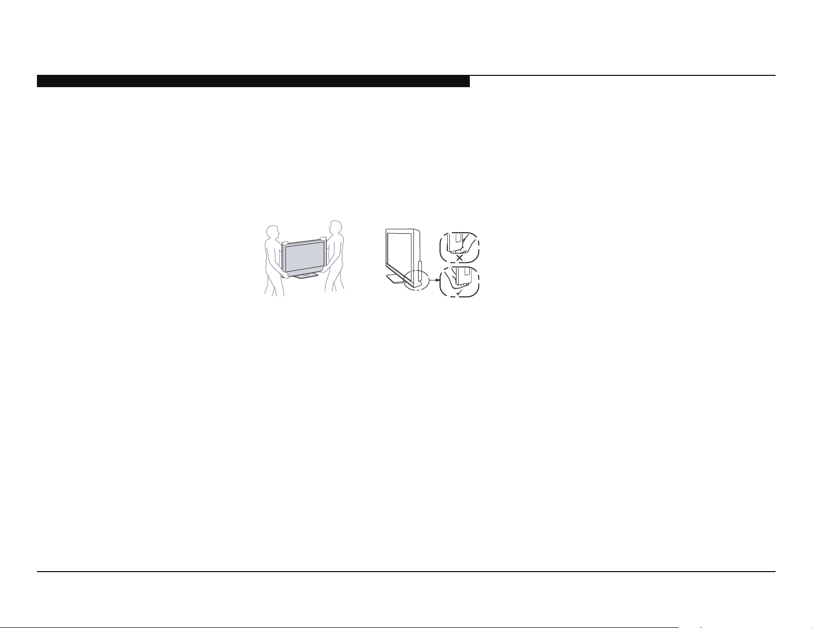
CARRYING THE TV
• Carry the TV with the adequate number of people; larger size TVs require two or more people.
• Correct hand placement while carrying the TV is very important for safety and to avoid
damage.
WARNING!!
An isolation transformer should be used during any service to avoid possible shock hazard, because of live chassis. The chassis of this
receiver is directly connected to the AC power line.
! SAFETY-RELATED COMPONENT WARNING!!
Components identifi ed by shading and ! mark on the exploded views are critical for safe operation.
Replace all components with Sony parts whose part numbers appear as shown in this manual or in supplements published by Sony. It is
essential that all critical parts be replaced only with the part number specifi ed in this manual to prevent electric shock, fi re, or other hazard.
Circuit adjustments that are critical for safe operation are identifi ed in this manual.
Follow these procedures whenever critical components are replaced or improper operation is suspected.
NOTE: Do not modify the original design without obtaining written permission from the manufacturer or you will void the original parts and
labor guarantee.
KDL-32EX700/40EX700/40EX703/46EX700/46EX701/46EX703/ 3
52EX700/52EX701/52EX703/60EX700/60EX701/60EX703
ATTENTION!!
Ces instructions de service sont à l’usage du personnel de service qualifi é seulement. Pour prévenir le risque de choc électrique, ne pas faire
l’entretien autre que celui contenu dans le Mode d’emploi à moins que vous soyez qualifi é faire ainsi.
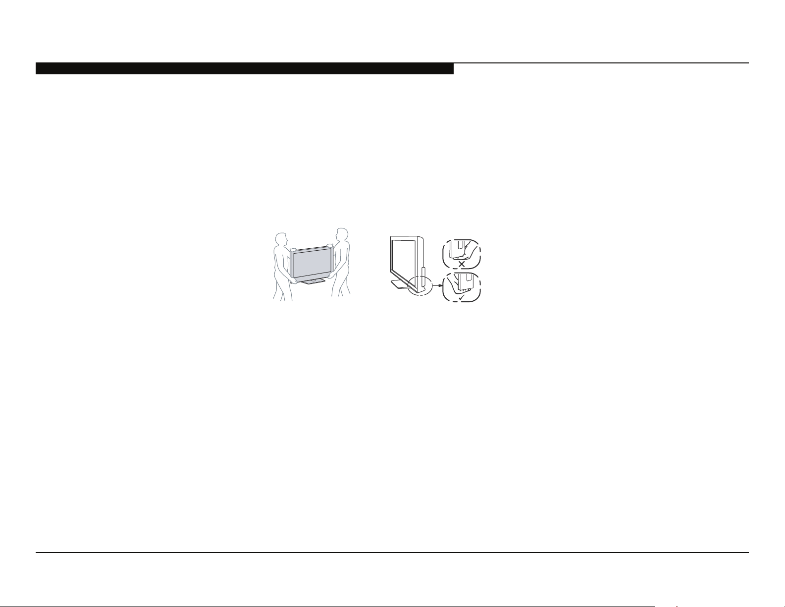
POUR TRANSPORTER LE TÉLÉVISEUR
• Transportez le téléviseur avec le nombre de personnes approprié ; un téléviseur de grande
taille doit être transporté par au moins deux personnes.
• Lors du transport du téléviseur, l’emplacement des mains est très important pour votre
sécurité, ainsi que pour éviter de causer des dommages.
ALERTE!!
Afi n d’eviter tout risque d’electrocution provenant d’un chássis sous tension, un transformateur d’isolement doit etre utilisé lors de tout
dépannage. Le chássis de ce récepteur est directement raccordé à l’alimentation du secteur.
WARNING AND CAUTIONS
! ATTENTION AUX COMPOSANTS RELATIFS A LA SECURITE!!
Les composants identifi es par une trame et par une marque ! sur les schemas de principe, les vues explosees et les listes de pieces sont
d’une importance critique pour la securite du fonctionnement. Ne les remplacer que par des composants Sony dont le numero de piece est
indique dans le present manuel ou dans des supplements publies par Sony. Les reglages de circuit dont l’importance est critique pour la
securite du fonctionnement sont identifi es dans le present manuel. Suivre ces procedures lors de chaque remplacement de composants
critiques, ou lorsqu’un mauvais fonctionnement suspecte.
KDL-32EX700/40EX700/40EX703/46EX700/46EX701/46EX703/ 4
52EX700/52EX701/52EX703/60EX700/60EX701/60EX703
SAFETY-RELATED WARNING
USE CAUTION WHEN HANDLING THE LCD PANEL
When repairing the LCD panel, be sure you are grounded by using a wrist band.
When installing the LCD panel on a wall, the LCD panel must be secured using the 4 mounting holes on the rear cover.
1) Do not press on the panel or frame edge to avoid the risk of electric shock.
2) Do not scratch or press on the panel with any sharp objects.
3) Do not leave the module in high temperatures or in areas of high humidity for an extended period of time.
4) Do not expose the LCD panel to direct sunlight.
5) Avoid contact with water. It may cause a short circuit within the module.
6) Disconnect the AC power when replacing the inverter circuit.
(High voltage occurs at the inverter circuit at 650Vrms.)
7) Always clean the LCD panel with a soft cloth material.
8) Use care when handling the wires or connectors of the inverter circuit. Damaging the wires may cause a short.
9) Protect the panel from ESD to avoid damaging the electronic circuit (C-MOS).
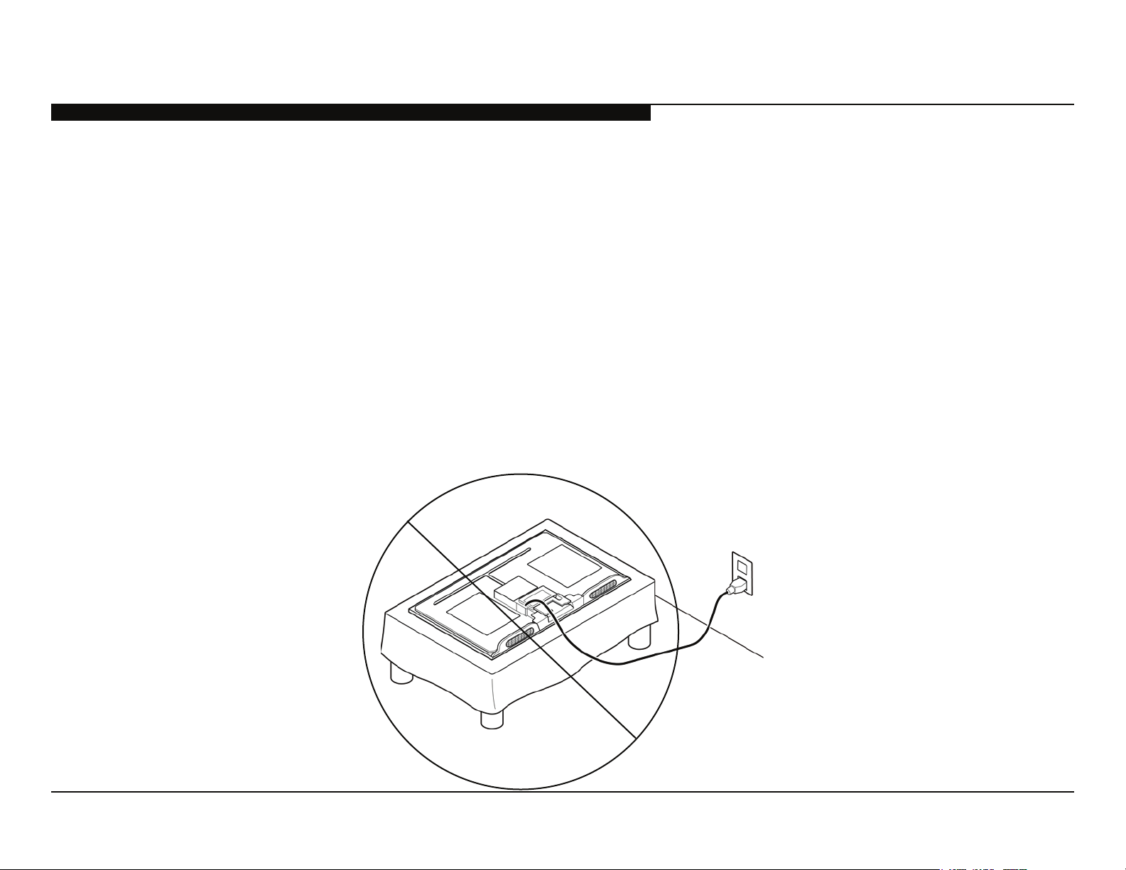
10) During the repair, DO NOT leave the Power On for more than 1 hour while the TV is face down on a cloth.
KDL-32EX700/40EX700/40EX703/46EX700/46EX701/46EX703/ 5
52EX700/52EX701/52EX703/60EX700/60EX701/60EX703
SAFETY CHECK-OUT
After correcting the original service problem, perform the following safety checks before releasing the set to the customer:
1. Check the area of your repair for unsoldered or poorly soldered connections.
Check the entire board surface for solder splashes and bridges.
2. Check the interboard wiring to ensure that no wires are “pinched” or touching
high-wattage resistors.
3. Check that all control knobs, shields, covers, ground straps, and mounting
hardware have been replaced. Be absolutely certain that you have replaced
all the insulators.
4. Look for unauthorized replacement parts, particularly transistors, that were
installed during a previous repair. Point them out to the customer and
recommend their replacement.
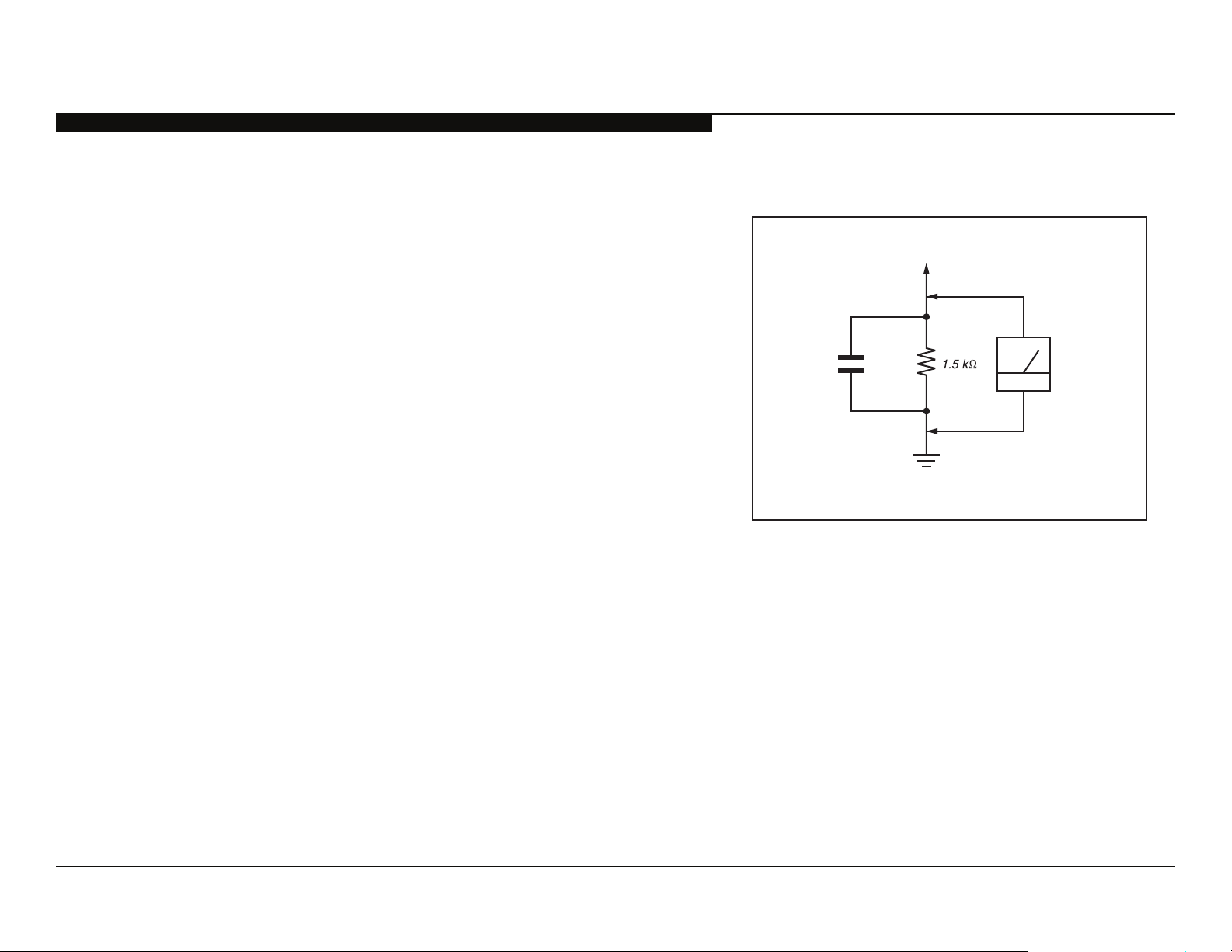
0.15 μF
To Exposed Metal
Parts on Set
AC
Voltmeter
(0.75V)
5. Look for parts which, though functioning, show obvious signs of deterioration.
Point them out to the customer and recommend their replacement.
6. Check the line cords for cracks and abrasion. Recommend the replacement
of any such line cord to the customer.
7. Check the antenna terminals, metal trim, “metallized” knobs, screws, and
all other exposed metal parts for AC leakage. Check leakage as described
below.
Figure A. Using an AC voltmeter to check AC leakage.
Earth Ground
KDL-32EX700/40EX700/40EX703/46EX700/46EX701/46EX703/ 6
52EX700/52EX701/52EX703/60EX700/60EX701/60EX703
LEAKAGE TEST
The AC leakage from any exposed metal part to earth ground and from all
exposed metal parts to any exposed metal part having a return to chassis, must
not exceed 0.5 mA(500 microamperes). Leakage current can be measured by
any one of three methods.
1. A commercial leakage tester, such as the Simpson 229 or RCA WT-540A.
Follow the manufacturers’ instructions to use these instructions.
2. A battery-operated AC milliampmeter. The Data Precision 245 digital
multimeter is suitable for this job.
3. Measuring the voltage drop across a resistor by means of a VOM or batteryoperated AC voltmeter. The “limit” indication is 0.75 V, so analog meters
must have an accurate low voltage scale.
SAFETY CHECK-OUT
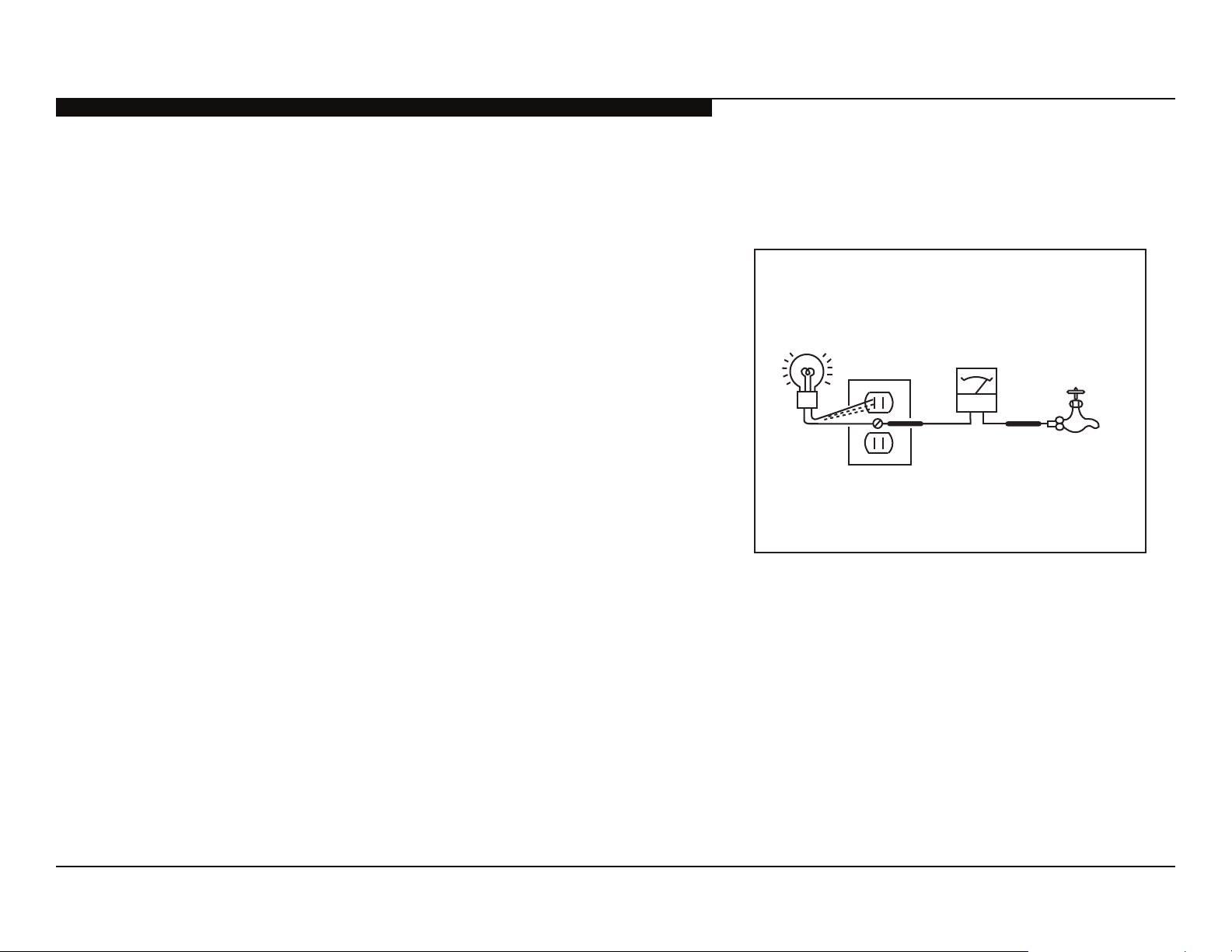
Trouble Light
AC Outlet Box
Ohmmeter
The Simpson’s 250 and Sanwa SH-63TRD are examples of passive VOMs
that are suitable. Nearly all battery-operated digital multimeters that have a
2 VAC range are suitable (see Figure A).
Cold-water Pipe
HOW TO FIND A GOOD EARTH GROUND
A cold-water pipe is a guaranteed earth ground; the cover-plate retaining screw
on most AC outlet boxes is also at earth ground.
If the retaining screw is to be used as your earth ground, verify that it is at
ground by measuring the resistance between it and a cold-water pipe with an
ohmmeter. The reading should be zero ohms.
If a cold-water pipe is not accessible, connect a 60-to 100-watt trouble-light (not
a neon lamp) between the hot side of the receptacle and the retaining screw.
Try both slots, if necessary, to locate the hot side on the line; the lamp should
light at normal brilliance if the screw is at ground potential (see Figure B).
KDL-32EX700/40EX700/40EX703/46EX700/46EX701/46EX703/ 7
52EX700/52EX701/52EX703/60EX700/60EX701/60EX703
Figure B. Checking for earth ground.
 Loading...