

Sony 454XRF Service Manual
SERVICE MANUAL
COMPACT DISC CHANGER SYSTEM
US Model
Canadian Model
CDX-454RF
E Model
CDX-454XRF
SPECIFICATIONS
CDX-454RF/454XRF
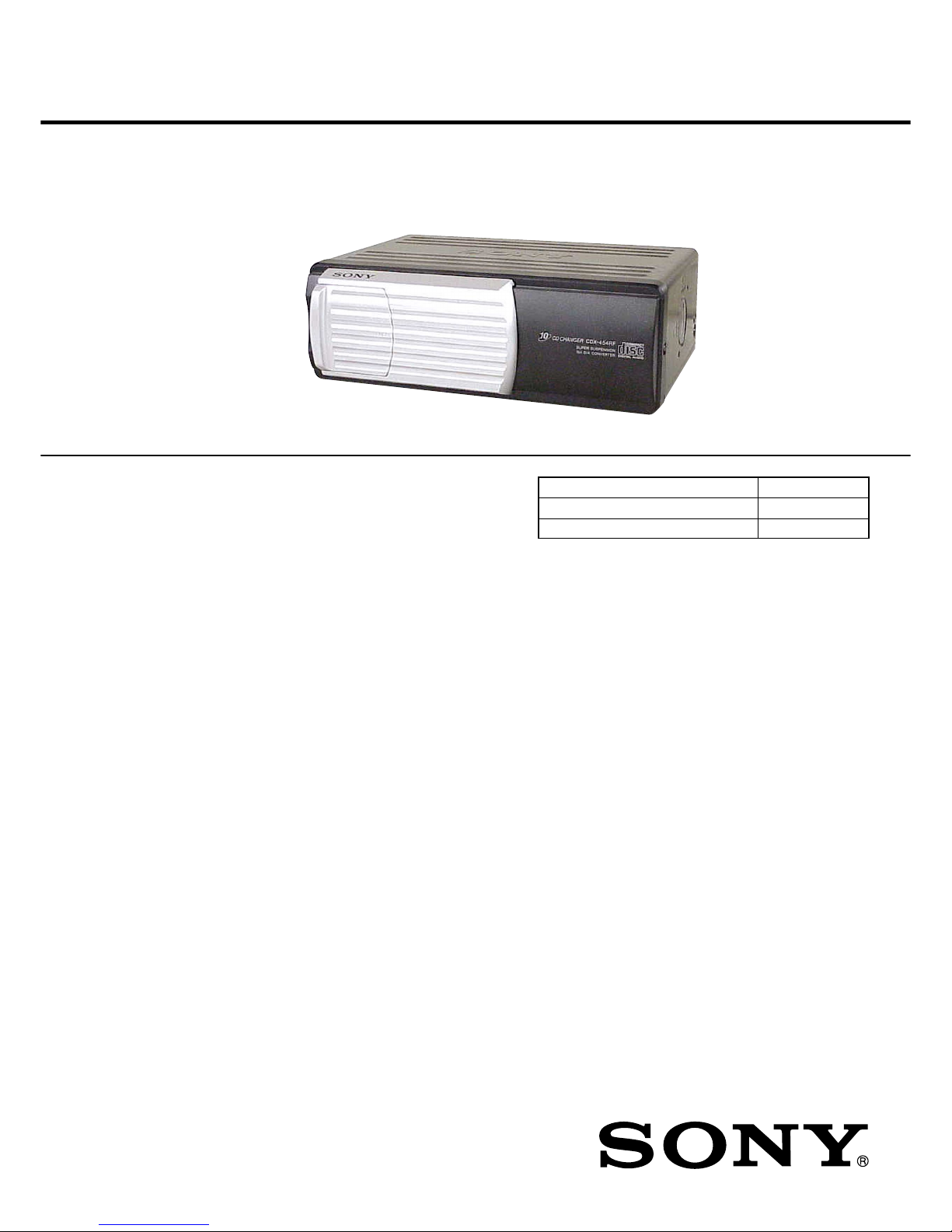
Photo: CDX-454RF
Ver 1.1 2002.03
9-873-373-02 Sony Corporation
2002C0500-1 e Vehicle Company
C 2002.03 Published by Sony Engineering Corporation
Model Name Using Similar Mechanism CDX-444RF
CD Drive Mechanism Type MG-251A-137
Optical Pick-up Name KSS-720A
CD changer
System Compact disc digital audio system
Transmitting
Laser Diode Properties
Material GaAlAs
Wavelength 780 nm
Emission Duration Continuous
Laser output power Less than 44.6 µW*
* This output is the value measured at a distance of 200 mm from the
objective lens surface on the Optical Pick-up Block.
frequency 88.3 MHz/88.5 MHz/
88.7 MHz/88.9 MHz/
89.1 MHz/89.3 MHz/
89.5 MHz/89.7 MHz/
89.9 MHz (switchable)
Input/output terminals Wired remote control
(8 pin)
RF signal (FM) output
Power input (3 pin)
Current drain 800 mA (at playback)
800 mA (at disc loading/
ejecting)
Operating temperature –10°C to +55°C
(14°F to 131°F)
Dimensions Approx. 262 × 90 ×
185 mm
(10
3
/8 × 3 5/8 × 7 3/8 in.)
(w/h/d)
Mass Approx. 2.1 kg (4 lb. 10 oz.)
Relay box
Input/output Aerial input terminal
Aerial output cord
CD changer input cord
Dimensions Approx. 40 × 40 × 27 mm
(1
5
/8 × 1 5/8 × 1 1/8 in.)
(w/h/d)
Mass Approx. 140 g (5 oz.)
Wired remote (RM-X82RF)
Dimensions Approx. 122 × 36.5 ×
15.5 mm
(4
7
/8 × 1 7/16 × 5/8 in.)
(w/h/d)
Mass Approx. 255 g (9 oz.)
General
Supplied accessories Disc magazine (1)
Parts for installation and
connections (1 set)
Design and specifications are subject to change
without notice.
2
CDX-454RF/454XRF
TABLE OF CONTENTS
1. SERVICING NOTES ................................................ 3
2. GENERAL
Location of controls ........................................................ 4
Installation....................................................................... 5
Connections ..................................................................... 7
3. DISASSEMBLY
3-1. Disassembly Flow .......................................................... 8
3-2. Case (Upper. T), Front Panel Assy ................................. 9
3-3. Mechanism Deck (MG-251A-137) ................................ 9
3-4. FM Board ........................................................................ 10
3-5. MAIN Board, Slide Variable Resistor
(Elevator Height Sensor) (RV202) ................................. 10
3-6. ELJ Motor Assy (Elevator) (M104)................................ 11
3-7. Escutcheon (T) ................................................................ 11
3-8. Chassis (U.S) Sub Assy .................................................. 12
3-9. Chassis assy..................................................................... 12
3-10. RF Board ......................................................................... 13
3-11. Sled Motor Assy (251) (M101),
Optical Pick-up (KSS-720A) .......................................... 13
3-12. LSW Board, Spindle Motor (S) Sub Assy (M102) ........ 14
3-13. ELJ Motor Assy (Chucking) (M103) ............................. 14
4. ASSEMBLY
4-1. Assembly Flow................................................................ 15
4-2. Optical Pick-up Complete Assy...................................... 15
4-3. Gear (Lomini)/(Load 1) Assy ......................................... 16
4-4. Operation Check ............................................................. 16
5. MECHANICAL ADJUSTMENTS....................... 17
6. ELECTRICAL CHECK .......................................... 18
7. DIAGRAMS
7-1. Block Diagram – SERVO Section – .............................. 21
7-2. Block Diagram – MAIN Section – ................................ 22
7-3. Note for Printed Wiring Boards and
Schematic Diagrams ....................................................... 23
7-4. Printed Wiring Boards – RF/LSW Boards – ................. 24
7-5. Schematic Diagram – RF/LSW Boards –...................... 25
7-6. Printed Wiring Board
– MAIN Board (Component Side) – .............................. 26
7-7. Printed Wiring Boards
– MAIN (Conductor Side)/SW Boards – ....................... 27
7-8. Schematic Diagram – MAIN Board (1/2) – .................. 28
7-9. Schematic Diagram – MAIN (2/2)/SW Boards – ......... 29
7-10. Printed Wiring Board – FM Board – ............................. 30
7-11. Schematic Diagram – FM Board – ................................. 31
7-12. IC Pin Function Description ........................................... 36
8. EXPLODED VIEWS
8-1. General Section-1............................................................ 38
8-2. General Section-2............................................................ 39
8-3. Mechanism Deck Section-1 (MG-251A-137)................ 40
8-4. Mechanism Deck Section-2 (MG-251A-137)................ 41
8-5. Mechanism Deck Section-3 (MG-251A-137)................ 42
8-6. Mechanism Deck Section-4 (MG-251A-137)................ 43
9. ELECTRICAL PARTS LIST ............................... 44
ATTENTION AU COMPOSANT AYANT RAPPORT
À LA SÉCURITÉ!
LES COMPOSANTS IDENTIFIÉS P AR UNE MARQUE 0
SUR LES DIAGRAMMES SCHÉMA TIQUES ET LA LISTE
DES PIÈCES SONT CRITIQUES POUR LA SÉCURITÉ
DE FONCTIONNEMENT. NE REMPLACER CES COMPOSANTS QUE PAR DES PIÈCES SONY DONT LES
NUMÉROS SONT DONNÉS DANS CE MANUEL OU
DANS LES SUPPLÉMENTS PUBLIÉS PAR SONY.
SAFETY-RELATED COMPONENT WARNING!!
COMPONENTS IDENTIFIED BY MARK 0 OR DOTTED
LINE WITH MARK 0 ON THE SCHEMATIC DIAGRAMS
AND IN THE PARTS LIST ARE CRITICAL TO SAFE
OPERATION. REPLACE THESE COMPONENTS WITH
SONY PARTS WHOSE PART NUMBERS APPEAR AS
SHOWN IN THIS MANUAL OR IN SUPPLEMENTS PUBLISHED BY SONY.
CAUTION
Use of controls or adjustments or performance of procedures
other than those specified herein may result in hazardous radiation exposure.
Notes on chip component replacement
• Never reuse a disconnected chip component.
• Notice that the minus side of a tantalum capacitor may be damaged by heat.
Flexible Circuit Board Repairing
• Keep the temperature of the soldering iron around 270 ˚C during repairing.
• Do not touch the soldering iron on the same conductor of the
circuit board (within 3 times).
• Be careful not to apply force on the conductor when soldering
or unsoldering.
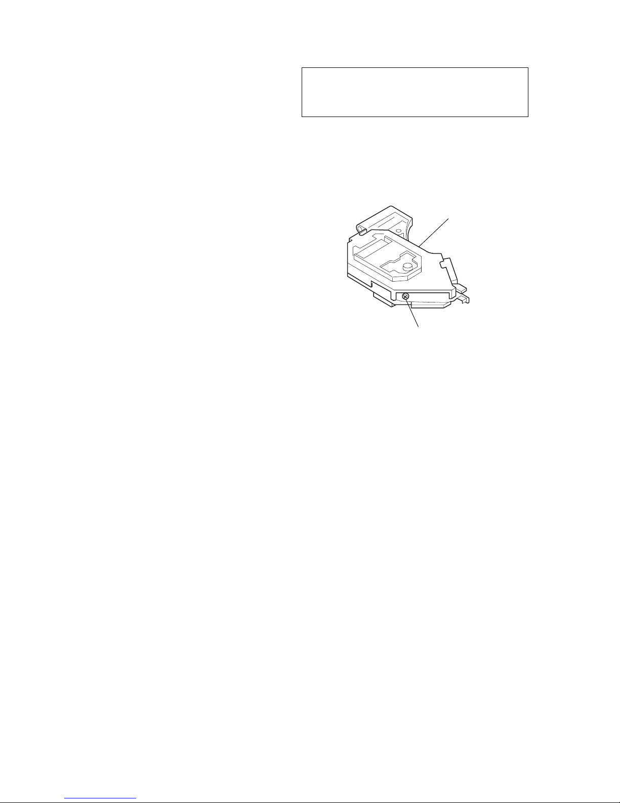
OPTICA
L
PICK-UP
BLOCK
SEMI-FIXED
RESISTOR
US/Canadian model:
If the optical pick-up block is defective, please replace the whole
optical pick-up block.
Never turn the semi-fixed resistor located at the side of optical
pick-up block.
3
CDX-454RF/454XRF
SECTION 1
SERVICING NOTES
DISC MAGAZINE GETTING OUT PROCEDURE
ON THE POWER SUPPLY IS OFF
Remove the COVER (LOWER.T) assy beforehand
1) Press the lever (ML.S) to arrow direction.
2) Removal the magazine assy.
Note: Take out the magazine only when the tray is completely within the
magazine. If the disk or tray is sticking out, turn on the power and
eject the magazine.
NOTES ON HANDLING THE OPTICAL PICKUP BLOCK OR BASE UNIT
Lever (ML.S)
Magazine assy
The laser diode in the optical pick-up block may suffer electrostatic breakdown because of the potential difference generated by
the charged electrostatic load, etc. on clothing and the human body .
During repair, pay attention to electrostatic breakdown and also
use the procedure in the printed matter which is included in the
repair parts.
The flexible board is easily damaged and should be handled with
care.
NOTES ON LASER DIODE EMISSION CHECK
The laser beam on this model is concentrated so as to be focused
on the disc reflective surface by the objective lens in the optical
pick-up block. Therefore, when checking the laser diode emission, observe from more than 30 cm away from the objective lens.
TEST DISC
This set can playback a CD-R, CD-RW for audio use. When test
this set, use the following test disc.
Test disc for CD-R: TCD-R082LMT (Part No.: J-2502-063-1)
Notes on CD-R/CD-RW discs
You can play CD-Rs (recordable CDs)
designed for audio use on this unit.
Look for this mark to
distinguish CD-Rs for audio
use.
This mark denotes that a
disc is not for audio use.
Some CD-Rs (depending on the equipment
used for its recording or the condition of
the disc) may not play on this unit.
You cannot play a CD-R that is not
finalized*.
You cannot play CD-RWs (rewritable CDs).
* A process necessary for a recorded CD-R disc to
be played on the audio CD player.
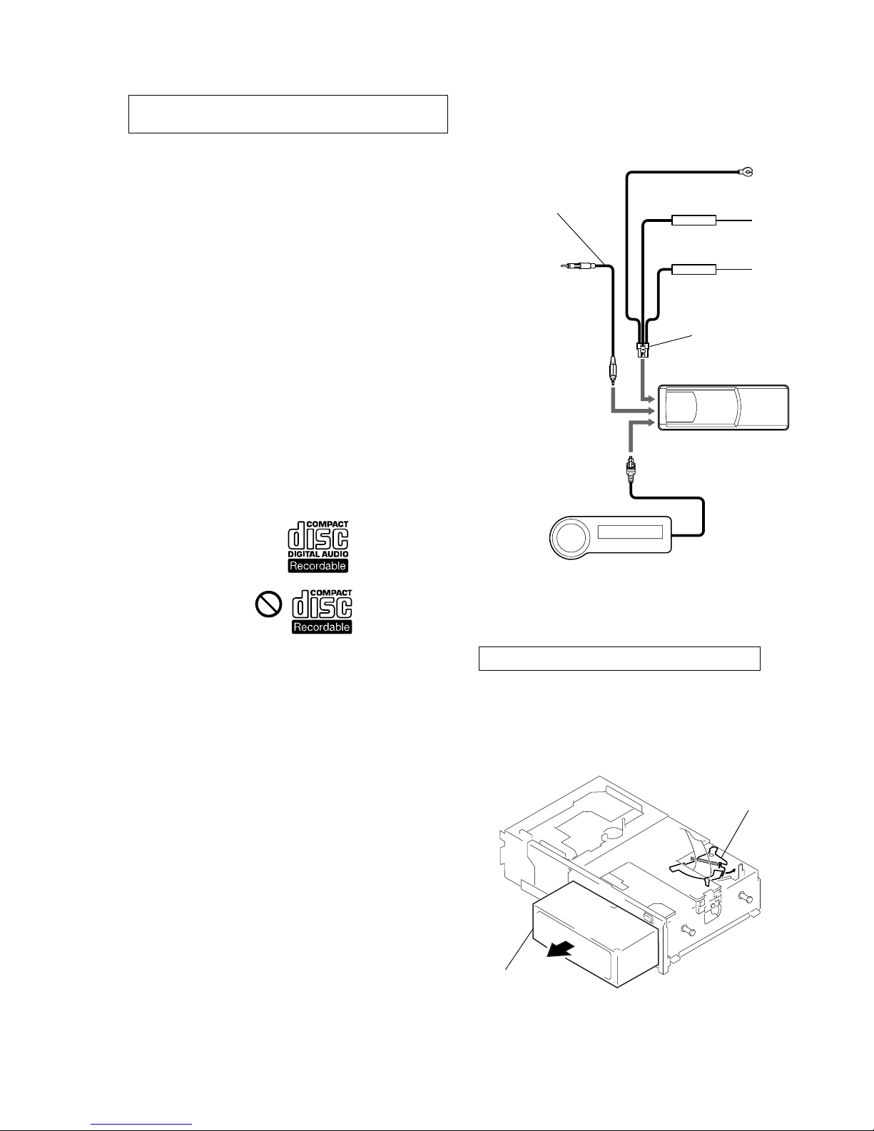
power supply cord
(J-2502-058-2)
compact disc changer
RF output cord
(J-2502-058-1)
wirerd remote commander
JIG ON REPAIRING
When repairing this set, connect the jig (cord) for RF output extract (Part No. J-2502-058-1) and power supply (Part No. J-2502058-2) as the figure shown below.
Ver 1.1
4
CDX-454RF/454XRF
SECTION 2
GENERAL
This section is extracted from
instruction manual.
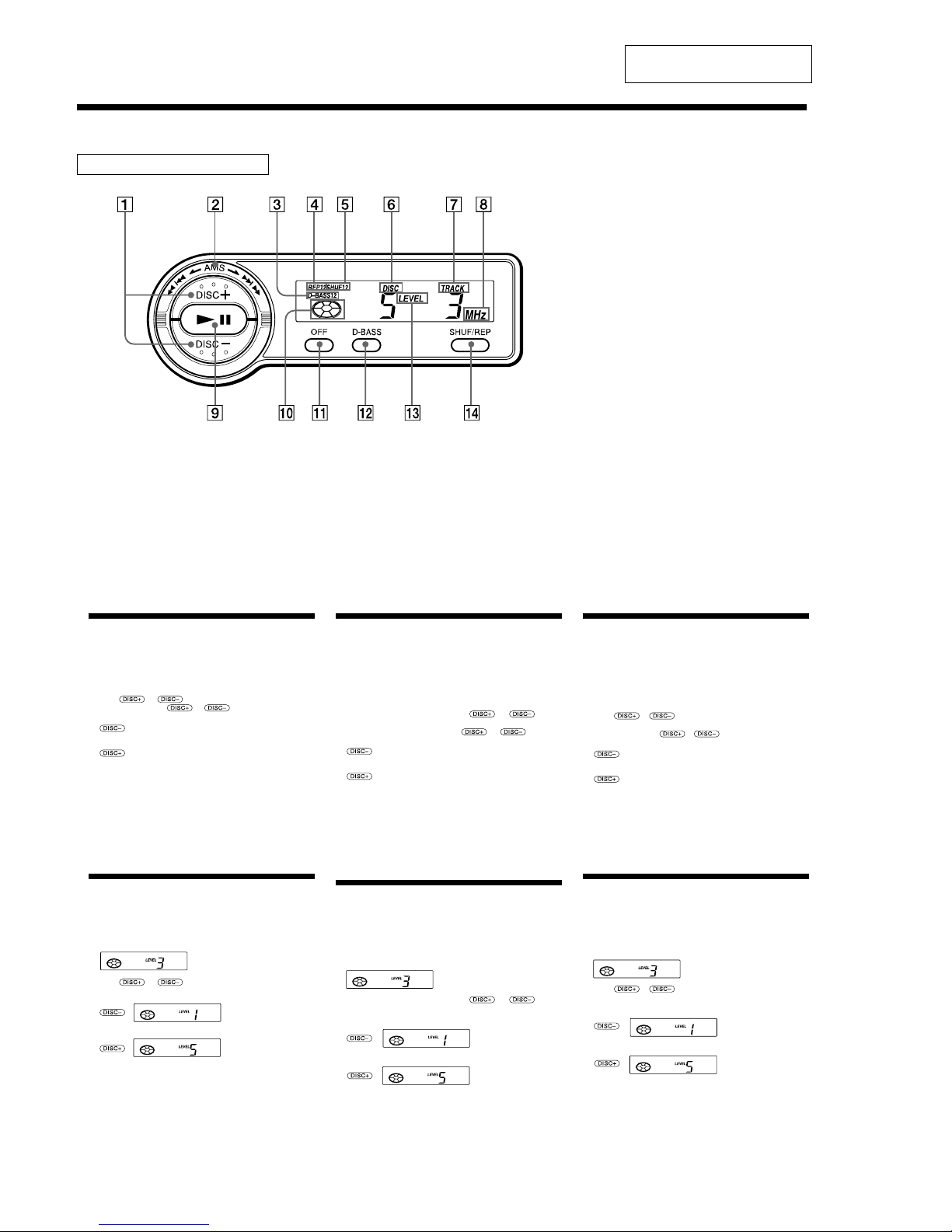
Location of controls
Wired remote (RM-X82RF)
Refer to the pages for details.
1 DISC (disc select) buttons 5, 6, 8
2 AMS (Automatic Music Sensor/manual
search) control 6
3 D-BASS indication 7
4 REP (repeat play) indication
5 SHUF (shuffle play) indication
6 DISC (disc number) indication
The indicated disc number matches the
disc number in the disc magazine.
7 TRACK (track number) indication
8 MHz (frequency) indication
9 u (play/pause) button 5, 6
If pressed during CD playback, the CD
will pause. If pressed again, CD playback
will continue.
0 Play/pause indication
Turns around during CD playback and
flashes when the pause button is pressed.
qa OFF button 6
qs D-BASS button 7
qd LEVEL (output level) indication
qf SHUF/REP (shuffle play/repeat play/
control mode set) button 5, 7, 8
Changing the transmitting frequency
Because this unit processes CD playback sound through an FM
tuner, there may be interference noise during CD playback. In such a
case, change the frequency of the modulated RF signal transmitted
from the unit. The initial setting is 88.3 MHz.
1 Press (SHUF/REP) for two seconds until frequency appears.
2 Press
or repeatedly to select the frequency.
Each time you press
or , the frequency changes
as follows:
:88.3 MHz t 89.9 MHz t 89.7 MHz t 89.5 MHz t
89.3 MHz t 89.1 MHz t 88.9 MHz t 88.7 MHz t
88.5 MHz t 88.3 MHz
:88.3 MHz t 88.5 MHz t 88.7 MHz t 88.9 MHz t
89.1 MHz t 89.3 MHz t 89.5 MHz t 89.7 MHz t
89.9 MHz t 88.3 MHz
3 Press (SHUF/REP) for two seconds.
Notes
• When you change the transmitting frequency on the unit, be sure to
tune your FM tuner to the newly selected one.
• Press u on the wired remote before changing the frequency if the
power to the unit is turned off.
Changing the Output Level
You can select the output level of the unit. Normally the unit is used
in the initial output level; change the level if necessary.
1 Press (SHUF/REP) for two seconds.
2 Press (SHUF/REP) momentarily.
3 Press or repeatedly to select the output level.
To decrease the output level
To increase the output level
4 Press (SHUF/REP) for two seconds.
Note
When you select level 4 or 5, the CD playback sound may be distorted or
you may hear some noise. In such a case, select a lower output level on the
unit and turn down the overall volume on your car audio.
Changement de la frquence de transmission
Comme cet appareil traite le son de lecture CD via un syntoniseur
FM, il se peut qu’il y ait des interférences durant la lecture du CD. En
pareil cas, changez la fréquence du signal RF modulé transmis par
l’appareil. Le réglage initial est de 88,3 MHz.
1 Appuyez sur (SHUF/REP) pendant deux secondes jusqu’à ce
que la fréquence apparaisse.
2 Appuyez plusieurs fois de suite sur
ou pour
sélectionner la fréquence.
Chaque fois que vous appuyez sur
ou , la
fréquence change dans l’ordre suivant :
:88.3 MHz t 89.9 MHz t 89.7 MHz t 89.5 MHz t
89.3 MHz t 89.1 MHz t 88.9 MHz t 88.7 MHz t
88.5 MHz t 88.3 MHz
: 88.3 MHz t 88.5 MHz t 88.7 MHz t 88.9 MHz t
89.1 MHz t 89.3 MHz t 89.5 MHz t 89.7 MHz t
89.9 MHz t 88.3 MHz
3 Appuyez sur (SHUF/REP) pendant deux secondes.
Remarques
• Si vous changez la fréquence de transmission de l’appareil, n’oubliez pas
de syntoniser votre syntoniseur FM sur la nouvelle fréquence
sélectionnée.
• Appuyez sur la touche u de la télécommande filaire avant de changer
la fréquence si l’appareil n’est pas sous tension.
Changement du niveau de sortie
Vous pouvez sélectionner le niveau de sortie de l’appareil. En
principe, l’appareil est utilisé au niveau de sortie initial ; changez le
niveau si nécessaire.
1 Appuyez sur (SHUF/REP) pendant deux secondes.
2 Appuyez brièvement sur (SHUF/REP).
3 Appuyez plusieurs fois de suite sur
ou pour
sélectionner le niveau de sortie.
Pour diminuer le niveau de sortie
Pour augmenter le niveau de sortie
4 Appuyez sur (SHUF/REP) pendant deux secondes.
Remarque
Si vous sélectionnez le niveau 4 ou 5, le son de lecture CD peut comporter
des distorsions ou des parasites. En pareil cas, sélectionnez un niveau de
sortie inférieure et baissez le volume de votre autoradio.
:
:
Initial setting
:
:
Ajuste inicial
Cambio de la frecuencia de transmisin
Puesto que esta unidad procesa el sonido de reproducción de CD
mediante un sintonizador de FM, es posible que se oiga ruido
producido por interferencias durante la reproducción de CD. En tal
caso, cambie la frecuencia de la señal RF modulada que transmite el
sistema. El ajuste inicial es 88,3 MHz.
1 Pulse (SHUF/REP) durante dos segundos hasta que aparezca
la frecuencia.
2 Pulse
o varias veces para seleccionar la
frecuencia.
Cada vez que pulse
o , la frecuencia cambiará de
la siguiente forma:
:88,3 MHz t 89,9 MHz t 89,7 MHz t 89,5 MHz t
89,3 MHz t 89,1 MHz t 88,9 MHz t 88,7 MHz t
88,5 MHz t 88,3 MHz
:88,3 MHz t 88,5 MHz t 88,7 MHz t 88,9 MHz t
89,1 MHz t 89,3 MHz t 89,5 MHz t 89,7 MHz t
89,9 MHz t 88,3 MHz
3 Pulse (SHUF/REP) durante dos segundos.
Nota
• Cuando cambie la frecuencia de transmisión de la unidad, asegúrese de
ajustar el sintonizador de FM en la frecuencia seleccionada.
• Pulse u en el mando alámbrico antes de cambiar la frecuencia si la
alimentación del sistema está desactivada.
Cambio del nivel de salida
Es posible seleccionar el nivel de salida del sistema. Normalmente el
sistema se utiliza con el nivel de salida inicial. Cámbielo si es
necesario.
1 Pulse (SHUF/REP) durante dos segundos.
2 Pulse (SHUF/REP) momentáneamente.
3 Pulse
o varias veces para seleccionar el nivel
de salida.
Para reducir el nivel de salida
Para aumentar el nivel de salida
4 Pulse (SHUF/REP) durante dos segundos.
Nota
Si selecciona el nivel 4 ó 5, es posible que el sonido de reproducción de CD
se distorsione o que se oiga cierto ruido. En tal caso, seleccione un nivel de
salida inferior en la unidad y disminuya el volumen general en el sistema
de audio del automóvil.
:
:
Réglage initial
5
CDX-454RF/454XRF
2
3
1
1
2
3
¿ 3.5 mm
(
5
/32 in.)
¿ 3,5 mm
(
5
/32 po.)
¿ 3,5 mm
CD changer
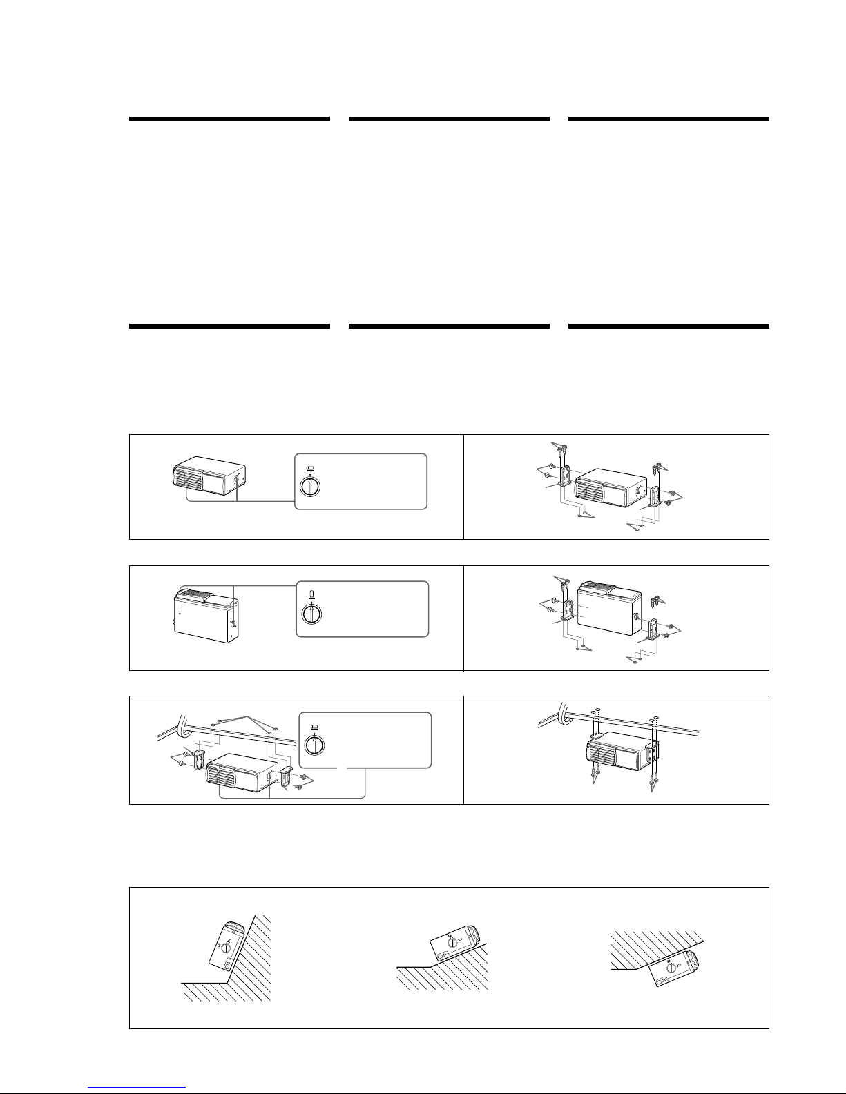
•Choose the mounting location carefully, observing the following:
— Do not install the unit where;
•the ambient temperature exceeds 55°C (131°F).
•it will be exposed to direct sunlight or hot air from a heater.
•it will be exposed to rain, water, or high humidity.
•it will be exposed to a lot of dust.
•it will be subject to excessive vibration.
— The fuel tank should not be damaged by the tapping screws.
— There should be no wire harnesses or pipelines under the place
where you are going to install the unit.
— The spare tire, tools, or other equipment in or under the trunk
should not be interfered with or damaged by the screws or the
unit itself.
Notes
• Be sure to use only the supplied mounting hardware for a safe and
secure installation.
• Make holes of ¿ 3.5 mm (
5
/32 in.) only after making sure there is nothing
on the other side of the mounting surface.
How to install the CD changer
•When you install the CD changer, be careful not to damage wiring
or equipment on the other side of the mounting surface.
•The brackets 1 provide two positions for mounting, high and low.
Use the appropriate screw holes according to your preference.
Cambiador de discos compactos
•Elija cuidadosamente el lugar de montaje teniendo en cuenta lo
siguiente:
— No instale la unidad donde:
•la temperatura ambiente sea superior a 55°C.
•quede expuesta a la luz solar directa o al aire caliente de un
calefactor.
•quede expuesta a lluvia, agua o mucha humedad.
•quede expuesta a polvo excesivo.
•quede sujeta a vibraciones excesivas.
— El depósito de combustible no deberá dañarse con los tornillos
autorroscantes.
— No deberá haber cables ni tubos debajo del lugar en el que vaya
a instalar la unidad.
— Ni los tornillos ni la propia unidad deberían dañar ni interferir
con la rueda de repuesto, las herramientas y demás equipos del
portaequipajes o situados debajo de éste.
Notas
• Para realizar una instalación firme y segura, cerciórese de utilizar
solamente la ferretería de montaje suministrada.
• Antes de hacer los orificios de ¿ 3,5 mm, compruebe que no haya nada
en el otro lado de la superficie de montaje.
Forma de instalar el cambiador de discos
compactos
•Cuando instale el cambiador de discos compactos, cerciórese de no
dañar el cableado ni los equipos que puedan encontrarse en la otra
parte de la superficie de montaje.
•Los soportes 1 proporcionan dos posiciones de montaje, alta y
baja. Utilice los orificios para tornillo apropiados según sus
preferencias.
Instalacin horizontal
1
Vertical installation Installation verticale
1
2
Suspended installation Installation suspendue
1
2
When the unit is to be installed under the rear tray or in the trunk,
observe the following.
•Choose the mounting location carefully so that the unit can be
installed horizontally.
•Make sure the unit does not hinder the action of the torsion bar
spring, hinge, etc. of the deck lid.
Cuando vaya a instalar la unidad debajo de la bandeja trasera o en el
portaequipajes, tenga en cuenta lo siguiente.
•Elija cuidadosamente el lugar de montaje de forma que la unidad
pueda instalarse horizontalmente.
•Asegúrese de que la unidad no dificulta la acción del resorte de la
barra de torsión, la bisagra, etc. de la tapa de la platina.
Inclined installation Installation incline
Après avoir installé l’appareil, alignez les disques sur l’un des repères
afin que la flèche soit aussi proche que possible de la position
verticale.
After installing the unit, align the dials with one of the marks
so
that the arrow comes as close to a vertical position as
possible.
2
Remarque
Veillez à aligner les disques gauche et droite sur le même repère.
Note
Be sure to align the left and right dials with the same mark.
H
O
R
I
Z
O
N
T
A
L
V
E
R
T
I
C
A
L
H
O
R
I
ZO
N
T
A
L
V
E
R
T
I
CA
L
HO
RIZONTAL
V
E
R
T
I
C
A
L
Horizontal installation
HORIZONTAL
Align with the marked position.
Alignez sur le repère.
Alinee con la posición marcada.
VERTICAL
Align with the marked position.
Alignez sur le repère.
Alinee con la posición marcada.
2
1
3
1
2
3
HORIZONTAL
Align with the marked position.
Alignez sur le repère.
Alinee con la posición marcada.
2
1
1
2
3
3
Installation Instalacin
Changeur de CD
•Choisir l’emplacement de montage en tenant compte des
observations suivantes
— N’installez pas l’appareil à un endroit :
• soumis à une température ambiante supérieure à 55°C (131°F) ;
• exposé au rayonnement direct du soleil ou à un conduit d’air
chaud ;
• exposé à la pluie, à de l’eau ou à une forte humidité ;
• exposé à un fort empoussièrement ;
• soumis à des vibrations excessives.
— Vérifiez que le réservoir d’essence ne risque pas d’être
endommagé par les vis taraudeuses.
— Il ne doit pas y avoir de faisceaux de fils ou de tuyaux sous
l’emplacement du montage.
— Vérifiez que l’appareil ou les vis ne risquent pas d’endommager
ou de gêner la roue de secours, les outils ou un autre objet dans
le coffre.
Remarques
• Pour garantir la sécurité de l’installation, utilisez uniquement le matériel
de montage fourni.
• Ne percez les trous de 3,5 mm (
5
/32 po.) ø qu’après vous être assuré qu’il
n’y avait rien de l’autre côté de la surface de montage.
Installation du changeur de CD
•Quand vous installez le changeur de CD, veillez à ne pas
endommager les câbles ou les instruments qui se trouvent de
l’autre côté.
•Les supports 1 offrent deux positions de montage, haut et bas.
Utilisez les trous de vissage appropriés en fonction de vos
préférences.
Installation
Installation horizontale
Instalacin vertical
¿ 3.5 mm
(
5
/32 in.)
¿ 3,5 mm
(
5
/32 po.)
¿ 3,5 mm
Instalacin suspendida
¿ 3.5 mm (5/32 in.)
¿ 3,5 mm (
5
/32 po.)
¿ 3,5 mm
Si vous comptez installer le changeur de CD sous la plage arrière ou
dans le coffre, prenez les précautions suivantes.
•Choisissez soigneusement l’emplacement pour que le changeur soit
à l’horizontale.
•Assurez-vous que l’appareil n’entrave pas l’action du ressort à
barre de torsion, des charnières, etc., du couvercle de la malle.
Instalacin sobre una superficie inclinada
Después de instalar la unidad, alinee los diales con una de las
marcas, de forma que la flecha quede orientada en posición
vertical tanto como sea posible.
Nota
Asegúreses de alinear los diales derecho e izquierdo con la misma
marca.
6
CDX-454RF/454XRF
Wired remote
•Avoid mounting it where it may:
— hinder normal driving activities.
— block the airbag (especially passenger-side)
in operations.
— jeopardize the passengers.
— be exposed to hot air from the heater.
— be exposed to direct sunlight.
•After installing the unit, make sure the unit
can be operated by the wired remote.
Tlcommande fil
•Evitez de l’installer dans des endroits où elle
pourrait :
— gêner la conduite normale du véhicule ;
— bloquer le fonctionnement du coussin
gonflable (airbag) (surtout côté passager) ;
— mettre les passagers en danger ;
— être exposée à l’air chaud d’un chauffage ;
— être exposée au rayonnement direct du
soleil.
•Après avoir installé l’appareil, assurez-vous
que l’appareil peut être contrôlé au moyen de
la télécommande filaire.
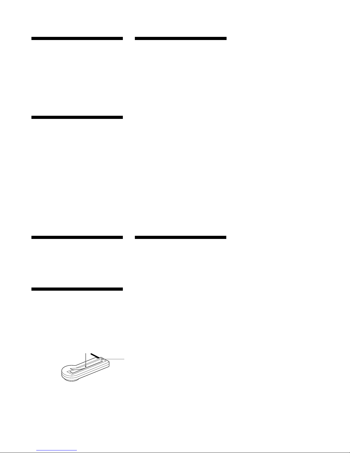
The back of the wired remote
Dos de la télécommande à fil
Parte posterior del mando a distancia alámbrico
4
Installing the wired remote
Use the supplied double-sided adhesive tape
4, and mount the wired remote in a suitable
location where it will not interfere with your
driving.
Installation de la
tlcommande fil
Utilisez la bande à double face adhésive fournie
4 pour installer la télécommande à fil dans un
endroit qui ne risque pas de gêner la conduite.
Instalacin del mando a
distancia almbrico
Utilice la cinta 4 adhesiva de doble cara
suministrada e instale el mando a distancia
alámbrico en un lugar adecuado que no
interfiera en la conducción.
Mando a distancia almbrico
•Evite montarlo donde pueda:
— estorbar las operaciones normales de
conducción.
— bloquear el funcionamiento del “airbag”
(especialmente en el lado del
acompañante).
— molestar a los pasajeros.
— quedar expuesto al aire caliente del
calefactor.
— quedar expuesto a la luz solar directa.
•Una vez instalada la unidad, compruebe que
puede controlarla mediante el mando a
distancia alámbrico.
7
CDX-454RF/454XRF
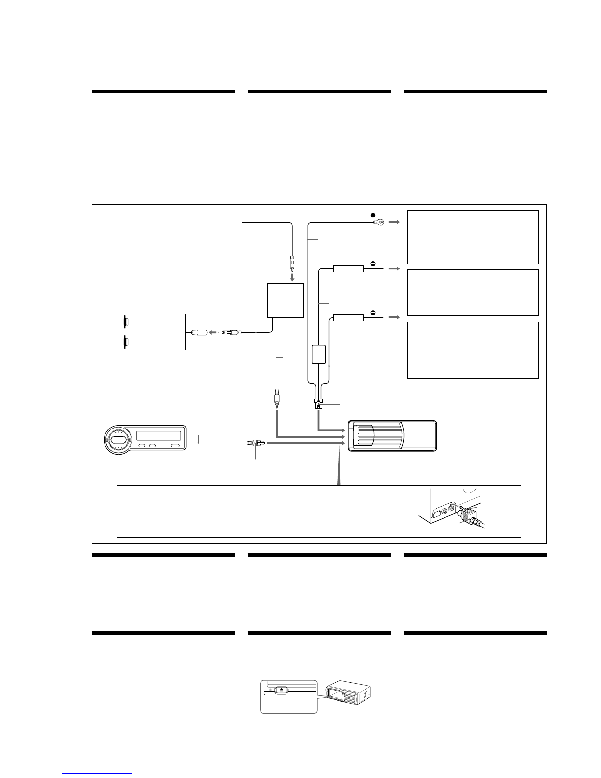
Connections
Caution
•This unit is designed for negative ground 12 V DC operation only.
•Before making connections, turn the car ignition off to avoid short
circuits.
•Connect the yellow and red power input leads only after all other
leads have been connected.
•Be sure to connect the red power input lead to the positive 12 V
power terminal which is powered when the ignition switch is in the
accessory position.
•Run all ground wires to a common ground point.
•When finished making all the connections, press the reset
button of the CD changer. (See “Reset button” below.)
•The use of optical instruments with this product will increase eye
hazard.
Conexiones
Prcautions
•Cet appareil est uniquement conçu pour fonctionner sur 12 V CC
avec une masse négative.
•Avant d’effectuer les raccordements, coupez le contact du véhicule
pour éviter tout court-circuit.
•Branchez les fils d‘entrée d‘alimentation jaune et rouge seulement
après avoir terminé tous les autres branchements.
•Veillez à ne pas raccorder le fil rouge d‘entrée d‘alimentation à la
borne positive de 12 V qui est alimentée quand la clé de contact est
sur la position accessoire.
•Rassemblez tous les fils de terre en un point de masse commun.
•Lorsque vous avez terminé toutes les connexions, appuyez sur
la touche de réinitialisation du changeur de CD. (Voir “Touche
de réinitialisation” ci-dessous.)
•L’utilisation d’instruments optiques avec ce produit augmente les
risques pour les yeux.
Remplacement du fusible
Si le fusible saute, vérifiez la connexion d’alimentation et remplacezle. Si le fusible saute à nouveau quand vous venez de le remplacer, il
s’agit peut être d’un mauvais fonctionnement interne.
Avertissement
Utilisez un fusible de l’ampérage spécifié.
L’utilisation d’un fusible d’ampérage supérieur peut causer de
sérieux dommages.
Touche de rinitialisation
Après avoir terminé l’installation et les connexions ou remplacé les
piles, appuyez sur la touche de réinitialisation du changeur de CD à
l’aide d’un stylo à bille, etc.
Fuse replacement
If the fuse blows, check the power connection and replace the fuse. If
the fuse blows again after replacement, there may be an internal
malfunction.
Warning
Use a fuse with the specified amperage rating.
Use of a higher amperage fuse may cause serious damage.
Reset button
After the installation and connections are completed or the batteries
have been changed, be sure to press the reset button with a ball-point
pen, etc.
WARNING
Plug the connector into the jack on
the left side of the CD changer.
Make sure that the catch of the
connector is secured in the hole
next to the jack.
AVERTISSEMENT
Branchez le connecteur sur la prise
du côté gauche du changeur de CD.
Assurez-vous que l’ergot du
connecteur s’adapte dans l’orifice à
côté de la prise.
to the +12 V power terminal which is powered at all times
Be sure to connect the black ground lead first.
à la borne d’alimentation +12 V qui est alimentée en
permanence
Raccordez d’abord le fil de masse noir.
a un terminal de +12 V que esté permanentemente energizado
Asegúrese de conectar en primer lugar el conductor de puesta
a masa negro.
to the +12 V power terminal which is powered when the
ignition switch is in the accessory position
Be sure to connect the black ground lead first.
à la borne d’alimentation de +12 V qui est alimentée quand la
clé de contact est sur la position accessoire
Raccordez d’abord le fil de masse noir.
a un terminal de +12 V que se energice al poner el interruptor
de encendido en la posición para accesorios
Asegúrese de conectar en primer lugar el conductor de puesta
a masa negro.
Fuse
Fusible
Fusible
5
Relay box
Boîtier de relais
Caja de relé
6
Wired remote
Télécommande à fil
Mando a distancia alámbrico
CD changer
Changeur de CD
Cambiador de discos compactos
Red
Rouge
Rojo
Black
Noir
Negro
Yellow
Jaune
Amarillo
Fuse
Fusible
Fusible
aerial connector
*
Connecteur d‘antenne*
Conector de antena*
Speaker system
Système de haut-parleurs
Sistema de altavoces
Car audio
Autoradio
Sistema de audio
del automóvil
from the car aerial*
depuis l’antenne de la voiture*
de la antena del automóvil*
Catch
Ergot
Retén
Reset button
Touche de réinitialisation
Botón de restauración
Insert the connector until it locks.
Insérez le connecteur jusqu’à ce qu’il
s’enclenche.
Inserte el conector hasta que quede
bloqueado.
* An adaptor (optional) may be necessary for your car and car
audio system. In such a case, consult your dealer.
* Un adaptateur (en option) peut s’avérer nécessaire suivant
votre voiture et votre autoradio. En pareil cas, consultez votre
revendeur.
* Es posible que sea necesario utilizar un adaptador (opcional)
para el automóvil y el sistema de audio de éste. En tal caso,
consulte con el proveedor.
Connector
Connecteur
Conector
1 m
5 m
5 m
5.5 m
5,5 m
0.5 m
0,5 m
5 m
Conexiones
Precauciones
•Esta unidad está diseñada para emplearse solamente con negativo a
masa de CC 12 V.
•Antes de realizar las conexiones, desactive el encendido del
automóvil para evitar cortocircuitos.
•Conecte los conductores de entrada de alimentación amarillo y
rojo solamente después de haber conectado todos los demás.
•Cerciórese de conectar el conductor de entrada de alimentación rojo
a un terminal de alimentación de 12 V positivo que reciba
electricidad al poner el interruptor de encendido en la posición
para accesorios.
•Conecte todos los conductores de puesta a masa a un punto
común.
•Cuando finalice todas las conexiones, pulse el botón de
reposición del cambiador de CD. (Consulte “Botón de
restauración” más adelante.)
•La utilización de instrumentos ópticos con este producto
aumentará el riesgo de sufrir daños en la vista.
to a metal point on the car
First connect the black ground lead, then connect the yellow
and red power input leads.
vers un point métallique de la voiture
Branchez d’abord le fil de masse noir et, ensuite, les fils
d’entrée d’alimentation jaune et rouge.
a un punto metálico del automóvil
Conecte en primer lugar el conductor de puesta a masa negro
y, después, los conductores de entrada de alimentación
amarillo y rojo.
ADVERTENCIA
Enchufe el conector a la toma del
lateral izquierdo del cambiador de
CD. Compruebe que el retén del
conector queda inmovilizado en el
orificio situado junto a la toma.
Sustitucin del fusible
Si el fusible se funde, verifique la conexión de alimentación y
sustitúyalo. Si una vez sustituido vuelve a fundirse, puede deberse a
un funcionamiento interno defectuoso.
Precaucin
Emplee un fusible del amperaje especificado.
El uso de un fusible de amperaje superior puede provocar daños
serios.
Botn de reposicin
Una vez completadas la instalación y las conexiones o después de
cambiar las pilas, asegúrese de pulsar el botón de restauración con
un bolígrafo, etc.
CDX-454RF/454XRF
8
• This set can be disassembled in the order shown below.
SECTION 3
DISASSEMBLY
3-1. DISASSEMBLY FLOW
3-2. CASE (UPPER.T),
FRONT PANEL ASSY
(Page 9)
3-3. MECHANISM DECK
(MG-251A-137)
(Page 9)
3-4. FM BOARD
(Page 10)
3-7. ESCUTCHEON (T)
(Page 11)
3-8. CHASSIS (U.S) SUB ASSY
(Page 12)
3-5. MAIN BOARD,
SLIDE VARIABLE RESISTOR
(ELEVATOR HEIGHT SENSOR) (RV202)
(Page 10)
3-6. ELJ MOTOR ASSY
(ELEVATOR) (M104)
(Page 11)
3-9. CHASSIS ASSY
(Page 12)
3-10. RF BOARD
(Page 13)
3-13. ELJ MOTOR ASSY (CHUCKING) (M103)
(Page 14)
3-11. SLED MOTOR ASSY (251) (M101),
OPTICAL PICK-UP (KSS-720A)
(Page 13)
3-12. LSW BOARD,
SPINDLE MOTOR (S) SUB ASSY (M102)
(Page 14)
SET
Note 1: The process described in can be performed in any order.
Note 2: Without completing the process described in , the next process can not be performed.
CDX-454RF/454XRF
9
Note: Follow the disassembly procedure in the numerical order given.
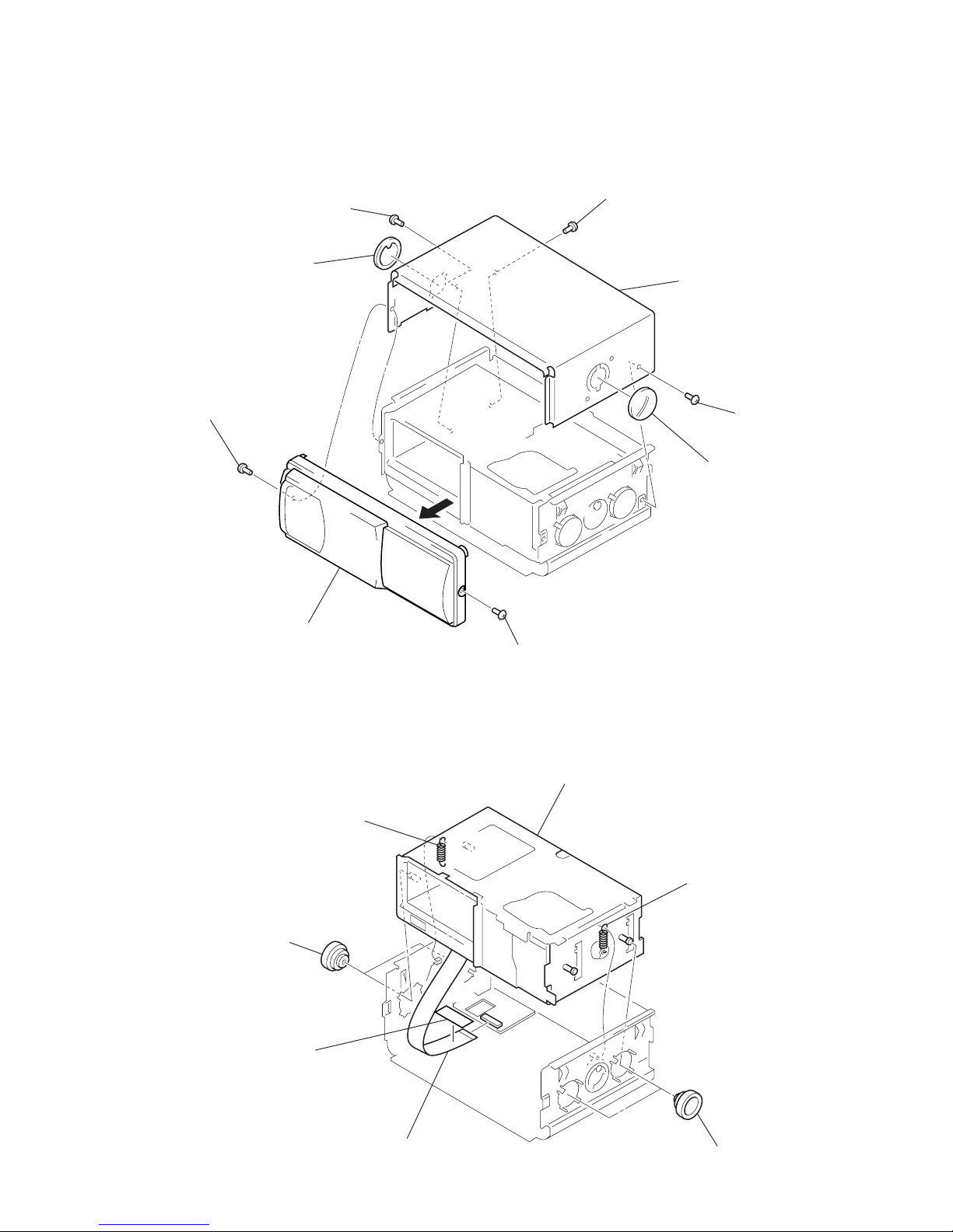
3-2. CASE (UPPER. T), FRONT PANEL ASSY
3
screw
(PTT2.6
×
6)
4
lever (FLT. 838)
3
screw (PTT2.6 × 6)
3
screw (PTT2.6 × 6)
1
screw (PTT2.6 × 6)
1
screw
(PTT2.6
×
6)
2
front panel assy
4
lever (FLT. 838)
5
case (upper. T)
3-3. MECHANISM DECK (MG-251A-137)
1
two dampers (T)
1
two dampers (T)
3
FM flexible board
(CN701)
filament tape
2
tension coil spring (FL
)
4
mechanism deck
(MG-251A-137)
2
tension coil spring (FL)
CDX-454RF/454XRF
10
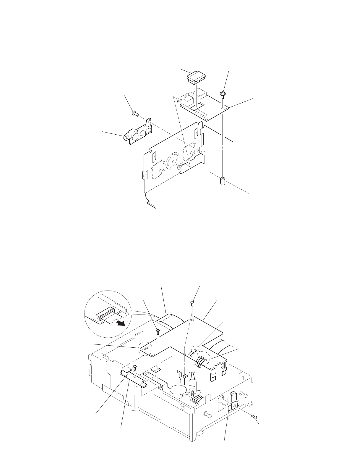
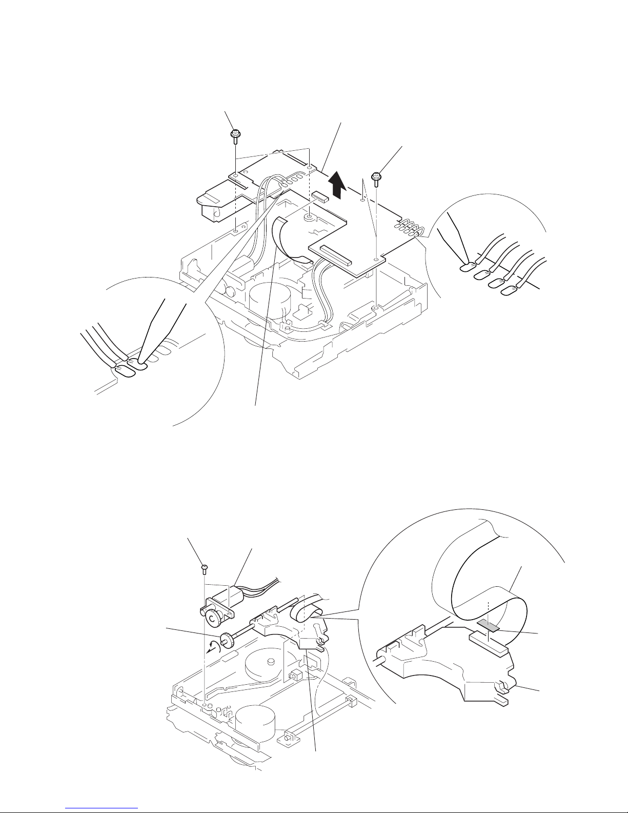
3-4. FM BOARD
3-5. MAIN BOARD, SLIDE VARIABLE RESISTOR (ELEVATOR HEIGHT SENSOR) (RV202)
1
screw
(BVTT2.6
×
6)
3
cover
(FM connector.T)
2
screw
(ground)
4
cover (FM)
5
FM boar
d
1
main flexible board
(CNJ101)
5
two screws (FP)
5
screw (FP)
6
main board
2
Remove two solders of
the elevator motor leads (M104).
2
Remove three solders
of the slide variable resistor
(RV202).
2
Remove four solders of
the SW board leads.
3
screw (PTT2 × 4)
4
heat sink (T)
8
slide variable resistor
(elevator height sensor)
(RV202)
7
screw
(PTT2
×
4)
CDX-454RF/454XRF
11
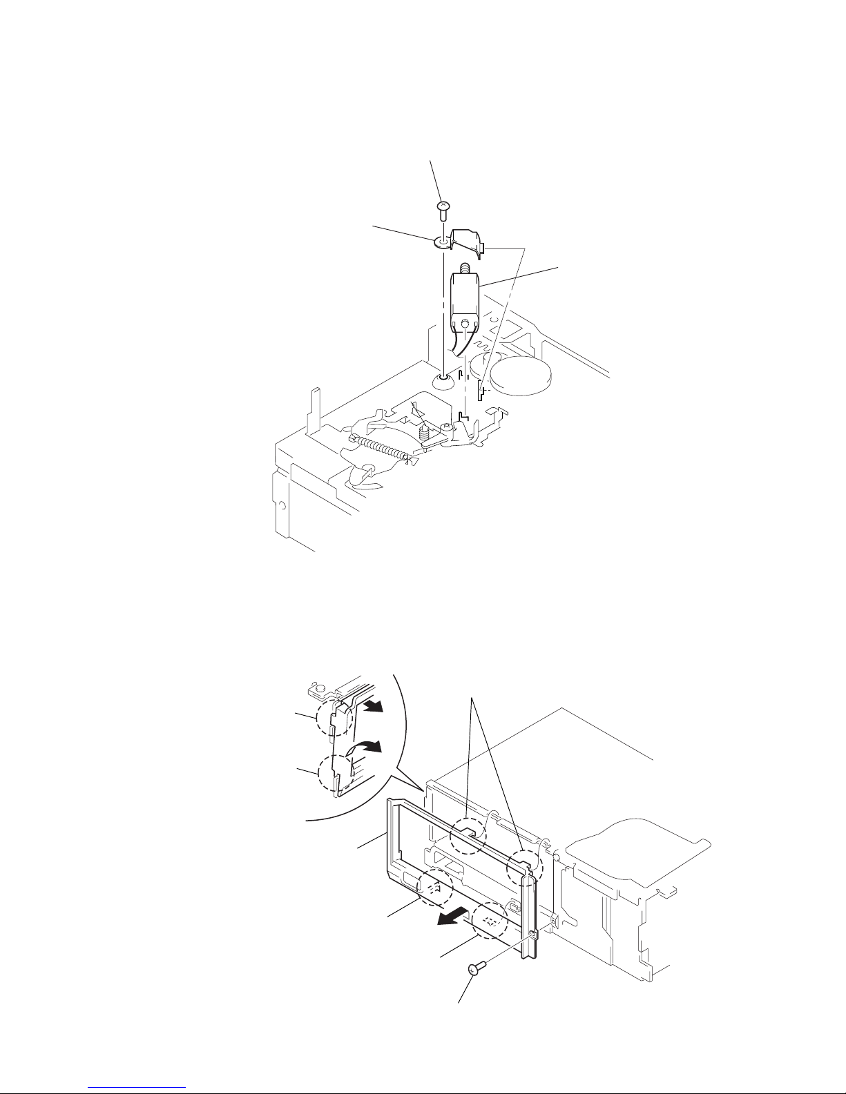
3-6. ELJ MOTOR ASSY (ELEVATOR) (M104)
3-7. ESCUTCHEON (T)
1
screw
(PTT2
×
4)
2
bracket (EVM.S)
3
ELJ motor assy (elevator)
(M104)
2
Remove the claw
in the direction of arrow
A
.
4
Remove the ditch
in the direction of arrow
B
.
A
B
5
Remove the escutcheon (T)
in the direction of arrow
C
.
4
ditch
3
claw
C
3
two claws
1
screw (T)
CDX-454RF/454XRF
12
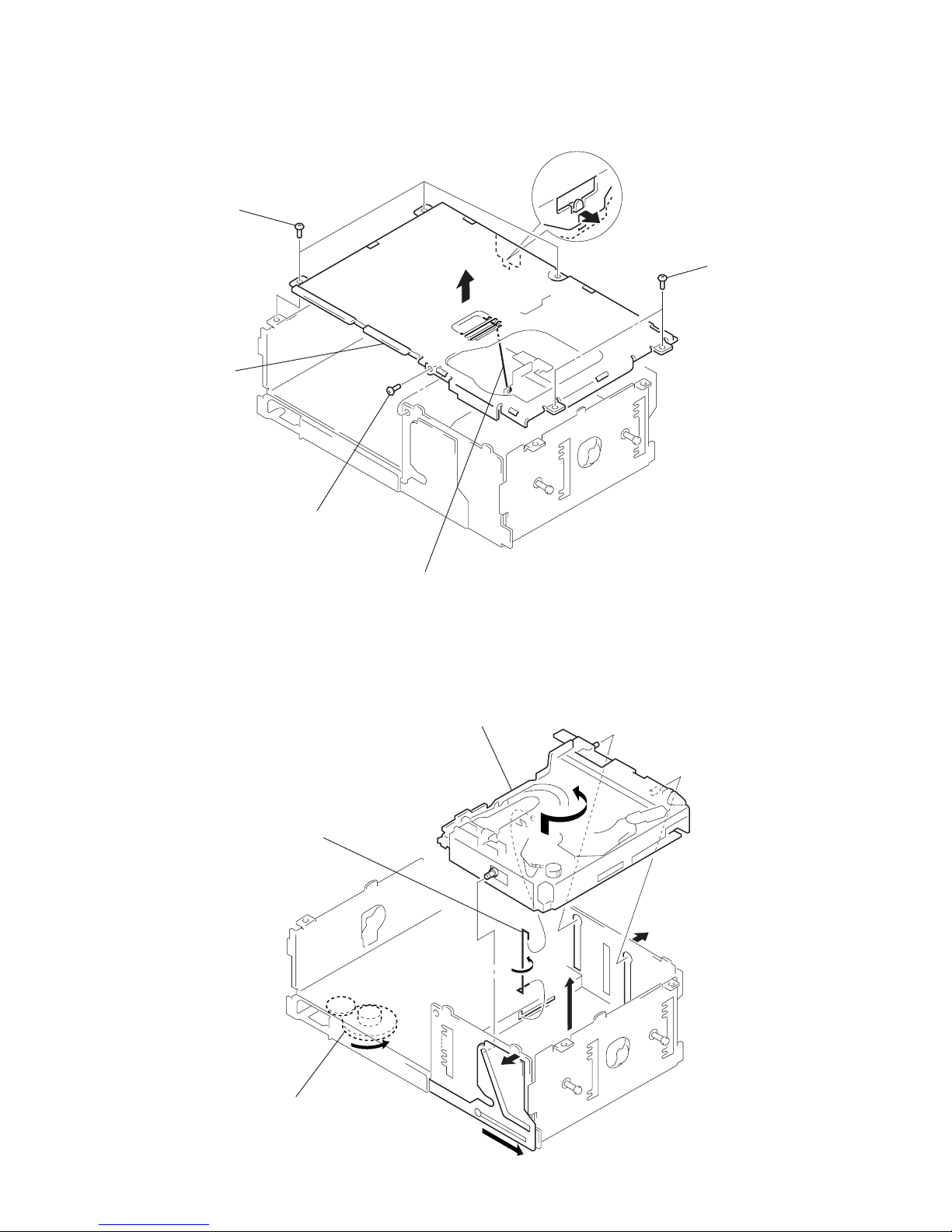
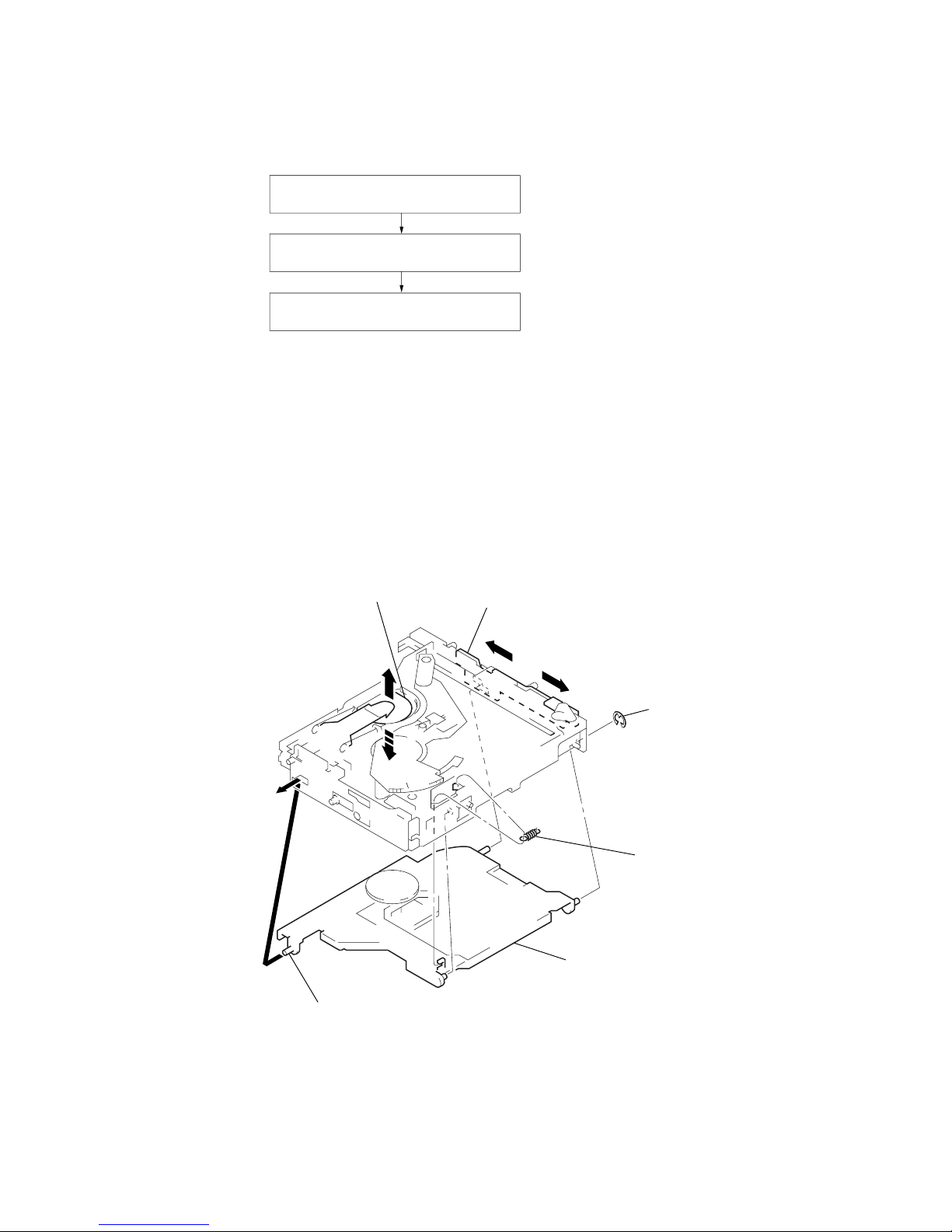
3-8. CHASSIS (U.S) SUB ASSY
3-9. CHASSIS ASSY
1
three screws
(PTT2 × 4)
1
screw
(PTT2 × 4)
1
two screws
(PTT2 × 4)
4
spring (SUT)
2
Remove the edge
in the direction
of arrow A.
5
chassis (U.S) sub assy
3
A
6
chassis assy
1
Turn the gear (EVD.S) fully
in the direction of arrow
A
.
5
spring (stopper.lower)
4
A
3
2
3
CDX-454RF/454XRF
13
3-10. RF BOARD
3-11. SLED MOTOR ASSY (251) (M101), OPTICAL PICK-UP (KSS-720A)
3
two screws
(PS2
×
4)
3
two screws
(PS2
×
4)
2
Remove four solders
of the LSW board leads
and spindle motor leads (M102).
2
Remove two solders
of the sled motor leads
(M101).
1
OP flexible board (CN102).
4
RF board
1
two precision screws
(P2
×
3)
4
Turn shaft (feed) assy
in the direction
of the arrow,
then remove it.
2
sled motor assy (251)
(M101)
OP flexible board
adhesive
sheet
3
optical pick-up
(KSS-720A)
optical
pick-up
Note: After connecting OP flexible board,
fix it with adhesive sheet
to optical pick-up.

CDX-454RF/454XRF
14
3-12. LSW BOARD, SPINDLE MOTOR (S) SUB ASSY (M102)
3-13. ELJ MOTOR ASSY (CHUCKING) (M103)
8
two precision screws
(P1.7
×
2.2)
7
3
spring (chucking)
6
retainer (disc
)
4
precision scre
w
(P2 × 2.2)
5
bracket (CP)
9
Remove the spindle motor (S) sub assy (M102)
in the direction of the arrow.
2
LSW board
1
precision screw
(P2
×
2.5)
2
two screws
(PTT2
×
4)
3
retainer (CHM)
4
ELJ motor
assy
(chucking)
(M103)
1
Remove two solders of
the chucking motor leads (M103).
CDX-454RF/454XRF
15
• This set can be assembled in the order shown below.
SECTION 4
ASSEMBLY
4-1. ASSEMBLY FLOW
4-2. OPTICAL PICK-UP COMPLETE ASSY
(Page 15)
4-3. GEAR (LOMINI) / (LOAD 1) ASSY
(Page 16)
4-4. OPERATION CHECK
(Page 16)
4-2. OPTICAL PICK-UP COMPLETE ASSY
chuck plate
1
Move the lever (LOCK 3A) in the direction of arrow A,
and return it a little in the direction of arrow
B
from the position where the chuck plate is moved
down to the lower limit.
A
B
3
stop ring 2.0 (E type
)
4
tension spring (DH)
2
optical pick-up complete assy
Note: Insert the shaft (A) first.
shaft (A)
 Loading...