

Sony 4-178-247-13-2 User Manual

4-178-247-13(2)
Blu-ray Disc/DVD
Home Theatre System
Operating Instructions
BDV-E870 / E370
©2010 Sony Corporation
WARNING
Do not install the appliance in a
confined space, such as a bookcase
or built-in cabinet.
To reduce the risk of fire, do not
cover the ven tilation opening of the
apparatus with newspapers,
tablecloths, curtains, etc. Do not
place the naked flame sources such
as lighted candles on the apparatus.
To reduce the risk of fire or electric
shock, do not expose this apparatus
to dripping or splashing, and do not
place objects filled with liquids,
such as vases, on the apparatus.
Do not expose batteries or
apparatus with battery-installed to
excessive heat such as sunshine,
fire or the like.
To prevent injury, this apparatus
must be securely attached to the
floor/wall in accordance with the
installation instructions.
Indoor use only.
CAUTION
The use of optical instruments with
this product will increase eye
hazard. As the laser beam used in
this Blu-ray Disc / DVD Home
Theatre System is harmful to eyes,
do not attempt to disassemble the
cabinet.
Refer servicing to qualified
personnel only.
This appliance is classified as a
CLASS 3R LASER product.
Visible and invisible laser radiation
is emitted when the laser protective
housing is opened, so be sure to
avoid direct eye exposure.
This marking is located on the laser
protective housing inside the
enclosure.
This appliance is classified as a
CLASS 1 LASER product. This
marking is located on the rear
exterior.
Disposal of
Old Electrical
& Electronic
Equipment
(Applicable in
the European
Union and other European
countries with separate
collection systems)
This symbol on the product or on its
packaging indicates that this
product shall not be treated as
household waste. Instead it shall be
handed over to the applicable
collection point for the recycling of
electrical and electronic equipment.
By ensuring this product is
disposed of correctly, you will help
prevent potential negative
consequences for the environment
and human health, which could
otherwise be caused by
inappropriate waste handling of
this product. The recycling of
materials will help to conserve
natural resources. For more
detailed information about
recycling of this product, please
contact your local Civic Office,
your household waste disposal
service or the shop where you
purchased the product.
Disposal of
waste batteries
(applicable in
the European
Union and other European
countries with separate
collection systems)
This symbol on th e battery or on the
packaging indicates that the battery
provided with this product shall not
be treated as household waste. On
certain batteries this symbol might
be used in combination with a
chemical symbol. The chemical
symbols for mercury (Hg) or lead
(Pb) are added if the battery
contains more than 0.0005%
mercury or 0.004% lead. By
ensuring these batteries are
disposed of correctly, you will help
prevent potentially negative
consequences for the environment
and human health which could
otherwise be caused by
inappropriate waste handling of the
battery. The recycling of the
materials will help to conserve
natural resources. In case of
products that for safety,
performance or data integrity
reasons require a permanent
connection with an incorporated
battery, this battery should be
replaced by qualified service staff
only. To ensure that the battery will
be treated properly, hand over the
product at end-of-life to the
applicable collection point for the
recycling of electrical and
electronic equipment. For all other
batteries, please view the section on
how to remove the battery from the
product safely. Hand the battery
over to the applicable collection
point for the recycling of waste
batteries. For more detailed
information about recycling of this
product or battery, please contact
your local Civic Office, your
household waste disposal servi ce or
the shop where you purchased the
product.
Notice for customers: the following
information is only applicable to
equipment sold in countries
applying EU directives.
The manufacturer of this product is
Sony Corporation, 1-7-1 Konan
Minato-ku Tokyo, 108-0075 Japa n.
The Authorized Representative for
EMC and product safety is Sony
Deutschland GmbH, Hedelfinger
Strasse 61, 70327 Stuttgart,
Germany. For any service or
GB
2

guarantee matters please refer to
the addresses given in separate
service or guarantee documents.
Precautions
This equipment has been tested and
found to comply with the limits set
out in the EMC Directive using a
connection cable shorter than 3
meters. (European and Russian
models only)
On power sources
• The unit is not disconnected from
the mains as long as it is
connected to the AC outlet, even
if the unit itself has been turned
off.
• As the main plug is used to
disconnect the unit from the
mains, connect the unit to an
easily accessible AC outlet.
Should you notice an abnormality
in the unit, disconnect the main
plug from the AC outlet
immediately.
On watching 3D video
images
Some people may experience
discomfort (such as eye strain,
fatigue, or nausea) while watching
3D video images. Sony
recommends that all viewers take
regular breaks while watching 3D
video images. The length and
frequency of necessary breaks will
vary from person to person. You
must decide what works best . If you
experience any discomfort, you
should stop watching the 3D video
images until the discomfort ends;
consult a doctor if you believe
necessary. You should also review
(i) the instruction ma nual and/or the
caution message of any other
device used with, or Blu-ray Disc
contents played with this product
and (ii) our website (for customers
in Europe and Russia: http://
www.sony-europe.com/
myproduct/; for customers in Asia
and Australia: http://www.sonyasia.com/support/) for the latest
information. The vision of young
children (especially those under six
years old) is still under
development. Consult your doctor
(such as a pediatrician or eye
doctor) before allowing young
children to watch 3D video images.
Adults should supervise young
children to ensure they follow the
recommendations listed above.
Copyrights and
Trademarks
• This system incorporates with
Dolby* Digital and Dolby Pro
Logic (II) adaptive matrix
surround decoder and the DTS**
Digital Surround System.
* Manufactured under license
from Dolby Laboratories.
Dolby, Pro Logic, and the
double-D symbol are
trademarks of Dolby
Laboratories.
** Manufactured under license
under U.S. Patent #’s:
5,451,942; 5,956,674;
5,974,380; 5,978,762;
6,226,616; 6,487,535;
7,212,872; 7,333,929;
7,392,195; 7,272,567 &
other U.S. and worldwide
patents issued & pending.
DTS is a registered
trademark and the DTS
logos, Symbol, DTS-HD
and DTS-HD Master Audio
are trademarks of DTS, Inc.
© 1996-2008 DTS, Inc. All
Rights Reserved.
• This system incorporates HighDefinition Multimedia Interface
TM
) technology.
(HDMI
HDMI, the HDMI logo and HighDefinition Multimedia Interface
are trademarks or registered
trademarks of HDMI Licensing
LLC.
• Java and all Java-based
trademarks and logos are
trademarks or registered
trademarks of Sun Microsystems,
Inc.
• “BD-LIVE” and
“BONUSVIEW” are trademarks
of Blu-ray Disc Association.
• “Blu-ray Disc” is a trademark.
• “Blu-ray Disc,” “DVD+RW,”
“DVD-RW,” “DVD+R,” “DVDR,” “DVD VIDEO,” and “CD”
logos are trademarks.
• “Blu-ray 3D” and “Blu-ray 3D”
logo are trademarks of Blu-ray
Disc Association.
• “BRAVIA” is a trademark of
Sony Corporation.
• “AVCHD” and the “AVCHD”
logo are trademarks of Matsushita
Electric Industrial Co., Ltd. and
Sony Corporation.
• “S-AIR” and its logo are
trademarks of Sony Corporation.
• , “XMB,” and “xross media
bar” are trademarks of Sony
Corporation and Sony Computer
Entertainment Inc.
• “PLAYSTATION” is a trademark
of Sony Computer Entertainment
Inc.
®
•DivX
, DivX Certified® and
associated logos are registered
trademarks of DivX, Inc. and are
used under license.
• Music and video recognition
technology and related data are
provided by Gracenote
Gracenote is the industry standard
in music recognition technology
and related content delivery. For
more information, please visit
www.gracenote.com.
CD, DVD, Blu-ray Disc, and
music and video-relate d data from
Gracenote, Inc., copyright ©
2000-present Gracenote.
Gracenote Software, copyright ©
2000-present Gracenote. One or
more patents owned by Grace note
apply to this product and service.
See the Gracenote website for a
nonexhaustive list of applicable
Gracenote patents. Gracenote,
CDDB, MusicID, MediaVOCS,
the Gracenote logo and logotype,
and the “Powered by Gracenote”
logo are either registered
trademarks or trademarks of
Gracenote in the United States
and/or other countries.
®
.
GB
3

• “PhotoTV HD” and the “PhotoTV
HD” logo are trademarks of Sony
Corporation.
• MPEG Layer-3 audio coding
technology and patents licensed
from Fraunhofer IIS and
Thomson.
• iPod is a trademark of Apple Inc.,
registered in the U.S. and other
countries.
• “Made for iPod” means that an
electronic accessory has been
designed to connect specifically
to iPod and has been certified by
the developer to meet Apple
performance standards.
• Apple is not responsible for the
operation of this device or its
compliance with safety and
regulatory standards.
• Windows Media is either a
registered trademark or trademark
of Microsoft Corporation in the
United States and/or other
countries.
®
, the DLNA Logo and
•DLNA
DLNA CERTIFIED™ are
trademarks, service marks, or
certification marks of the Digital
Living Network Alliance.
• Other system and product names
are generally trademarks or
registered trademarks of the
manufacturers. ™ and ® marks
are not indicated in this document.
About These Operating Instructions
• The instructions in these
Operating Instructions
describe the controls on the
remote. You can also use the
controls on the unit if they
have the same or similar
names as those on the remote.
• In this manual, “disc” is used
as a general reference for
BDs, DVDs, Super Audio
CDs, or CDs unl ess otherwise
specified by the text or
illustrations.
• The instructions in this
manual are for BDV-E870
and BDV-E370. BDV-E870
is the model used for
illustration purposes. Any
difference in operation is
clearly indicated in the text,
for example, “BDV-E870.”
• The items displayed on the
TV screen may vary
depending on the area.
• The default setting is
underlined.
• The system is compatible
with the S-AIR function,
which allows transmission of
sound between S-AIR
products wirelessly. For
details on the S-AIR function,
see “Using an S-AIR
Product” (page 41).
• Notes or instructions for the
surround amplifier, surround
back amplifier, or S-AIR
receiver in these Operating
Instructions refer only to
when the surround amplifier,
surround back amplifier, or
S-AIR receiver is used.
GB
4

Table of Contents
About These Operating Instructions ....... 4
Unpacking...............................................6
Index to Parts and Control ......................8
Getting Started
Step 1: Installing the System....... 13
Step 2: Connecting the System... 19
Step 3: Performing the Easy
Setup........................................ 25
Step 4: Selecting the Source....... 26
Step 5: Enjoying Surround
Sound....................................... 27
Playback
Playing a Disc .......................................29
Playing from a USB Device..................30
Enjoying an iPod...................................31
Playing via a Network...........................32
Available Options .................................34
Sound Adjustment
Selecting the Effect to Suit
the Source .......................................36
Selecting the Audio Format, Multilingual
Tracks, or Channel..........................36
Enjoying Multiplex Broadcast
Sound ..............................................37
Using the Sound Effect .........................37
Tuner
Listening to the Radio...........................39
Using the Radio Data System
(RDS)..............................................40
External Audio Device
Using an S-AIR Product .......................41
Other Operations
Using the Control for HDMI Function for
“BRAVIA” Sync ............................ 46
Calibrating the Appropriate Settings
Automatically .................................48
Setting the Speakers..............................49
Using the Sleep Timer .......................... 51
Deactivating the Buttons on
the Unit ...........................................51
Controlling Your TV with the Supplied
Remote ........................................... 51
Saving Power in Standby Mode ........... 51
Settings and Adjustments
Using the Setup Display ....................... 52
[Network Update]................................. 52
[Screen Settings]................................... 53
[Audio Settings].................................... 54
[BD/DVD Viewing Settings]................ 55
[Parental Control Settings] ................... 55
[Music Settings].................................... 56
[System Settings].................................. 56
[Network Settings]................................ 57
[Easy Setup].......................................... 58
[Resetting] ............................................ 58
Additional Information
Precautions............................................ 59
Notes about the Discs ........................... 60
Troubleshooting.................................... 61
Playable Discs....................................... 68
Playable Types of Files......................... 69
Supported Audio Formats..................... 70
Video Output Resolution ...................... 70
Specifications........................................ 71
Language Code List.............................. 73
Glossary................................................ 74
Index ..................................................... 77
GB
5
Unpacking
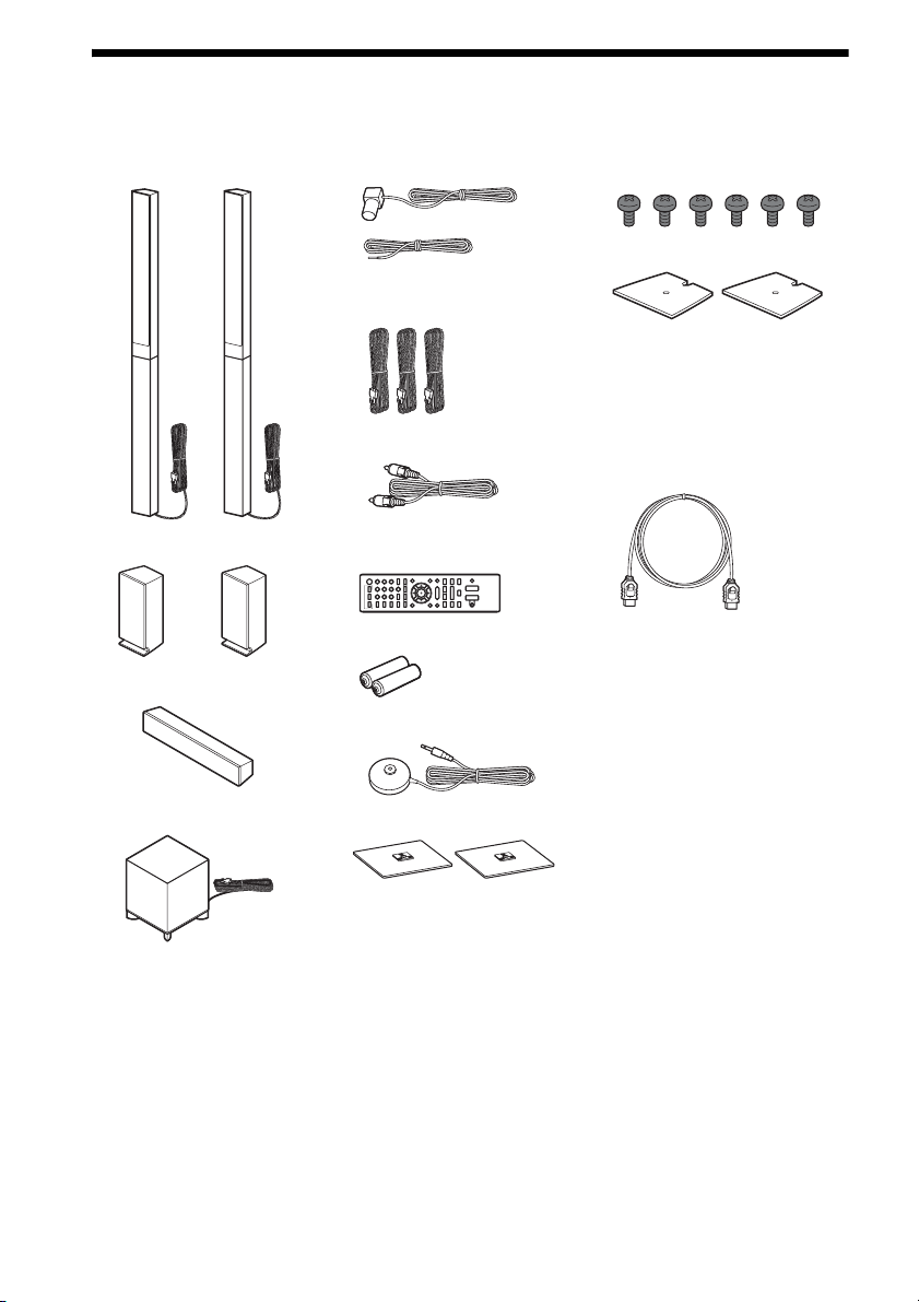
BDV-E870
• Front speakers (2)
• FM wire antenna (aerial) (1)
or
• Speaker cords (3, blue/gray/
green)
•Video cord (1)
• Screws (6)
• Speaker-bottom covers (2)
• Operating Instructions
• Speaker Installation Guide
• Quick Setup Guide
• End user license agreement
• HDMI cable (1)
(Taiwan models only)
• Surround speakers (2)
• Center speaker (1)
• Subwoofer (1)
• Remote commander
(remote) (1)
• R6 (size AA) batteries (2)
• Calibration mic (1)
• Bases (2)
GB
6

BDV-E370
• Front speakers (2)
• FM wire antenna (aerial) (1)
or
• Calibration mic (1)
• Operating Instructions
• Quick Setup Guide
• End user license agreement
• HDMI cable (1)
(Singapore, Thai, and
Taiwan models only)
• Surround speakers (2)
• Center speaker (1)
• Subwoofer (1)
• Speaker cords (5, white/red/
blue/gray/green)
• Video cord (1)
• Remote commander
(remote) (1)
• R6 (size AA) batteries (2)
Preparing the remote
Insert two R6 (size AA) batteries (supplied) by matching the 3 and # ends on the batteries to the
markings inside the compartment.
GB
7
Index to Parts and Control
For more information, refer to the pages indicated in parentheses.
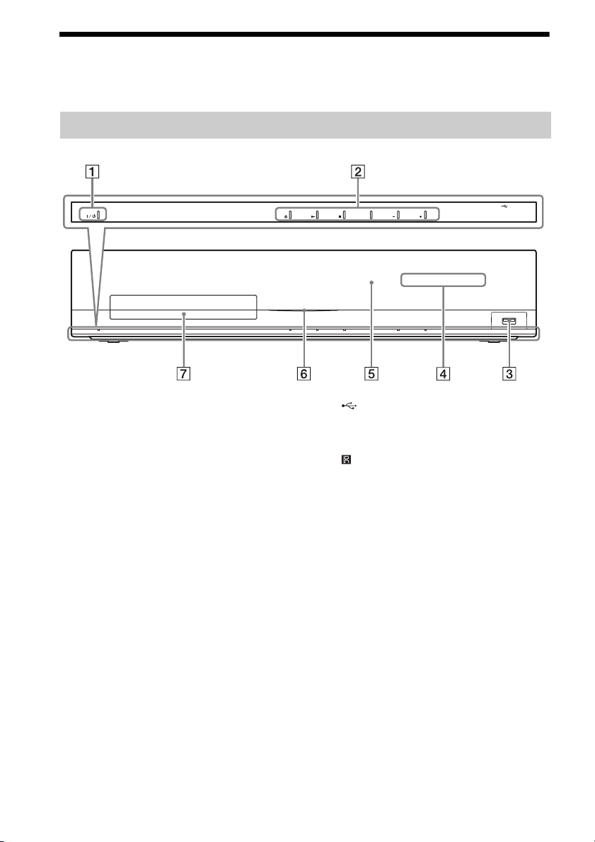
Front panel
FUNCTION VOLUME VOLUME
A "/1 (on/standby)
Turns on the unit, or sets it to standby mode.
B Play operation buttons
Z (open/close) (page 29)
Opens or closes the disc tray.
N (play)
Starts or re-starts playback (resume play).
Plays a slideshow when a disc containing
JPEG image files is inserted.
x (stop)
Stops playback and remembers the stop
point (resume point).
The resume point for a title/track is the last
point you played or the last photo for a
photo folder.
FUNCTION
Selects the playback source.
VOLUME +/–
Adjusts the system’s volume.
GB
8
C (USB) port (page 30)
Used for connecting a USB device.
D Front panel display
E (remote sensor)
F Power indicator
Lights up while the system is turned on.
G Disc tray (page 29)

Front panel display
About the indications in the front panel display
A Displays the current sound format.
B Lights up when the system is playing
via the PARTY STREAMING function.
C Lights up when outputting 1920 ×
1080p/24 Hz video signals.
D Lights up when outputting 720p/1080i/
1080p video signals from the HDMI
OUT jack or 720p/1080i video signals
from the COMPONENT VIDEO OUT
jacks.
E Lights up when the HDMI OUT jack is
correctly connected to an HDCP (Highbandwidth Digital Content Protection)compliant device with HDMI or DVI
(Digital Visual Interface) input.
F Lights up when a station is received.
(Radio only) (page 39)
G Lights up when stereo sound is
received. (Radio only) (page 39)
H Flashes when the sleep timer is set.
(page 51)
I S-AIR indicator (only when the wireless
transmitter (not supplied) is inserted
into the unit)
Lights up during wireless
transmission. Flashes when [Standby]
is set to [On] and the system is in
standby mode while wireless
transmission between the unit and
S-AIR receiver is not activated. (page
41)
J Displays system’s status such as
chapter, title, or track number, time
information, radio frequency, playing
status, surround setting, etc.
K Lights up when repeat play is
activated.
L Displays system’s playing status.
M Lights up when muting is on.
GB
9

Rear panel
SPEAKERS
FRONT R
FRONT L
SUBWOOFER CENTER
SPEAKERS
SUR R SUR L
LAN(100)
Y
COMPONENT VIDEO OUT
SAT/CABLE
DIGITAL IN
COAXIAL
VIDEO OUT
PB / CBPR / C
DIGITAL IN
TV
OPTICAL
Screws*
ARC
R
OUT
FM
COAXIAL
ANTENNA
A. CAL MIC
ECM-AC2
75
EZW-T100
AUDIO
AUDIO INRL
A (USB) port (page 30)
B LAN (100) terminal (page 24)
C COMPONENT VIDEO OUT jacks (page
20)
D VIDEO OUT jack (page 20)
E HDMI OUT jack (page 20)
F EZW-T100 slot (page 41)
G AUDIO (AUDIO IN L/R) jacks (page 22)
H A.CAL MIC jack (pages 25, 48)
I ANTENNA (FM COAXIAL 75Ω) jack
(page 23)
J TV (DIGITAL IN OPTICAL) jack (page
21)
K SAT/CABLE (DIGITAL IN COAXIAL)
jack (page 22)
L SPEAKERS jacks (page 19)
* CAUTION
Please do not remove the screws unless you
are installing the EZW-T100.
10
GB
Remote control
ONE-TOUCH
TV
PLAY
THEATRE
BRAVIA Sync
HOME
231
564
8097
D.TUNING
POP UP/ MENU
SOUND MODE
PRESET
TUNING
TV
TV
9
TOP MENU
RETURN OPTIONS
FUNCTION
PRESET
TUNING
8
SLEEP
SYSTEM
MENU
DISPLAY
Number 5, , 2 +, and N buttons have a
tactile dot. Use the tactile dot as a reference
when operating the remote.
• : For TV operations
(For details, see “Controlling Your TV with
the Supplied Remote” (page 51).)
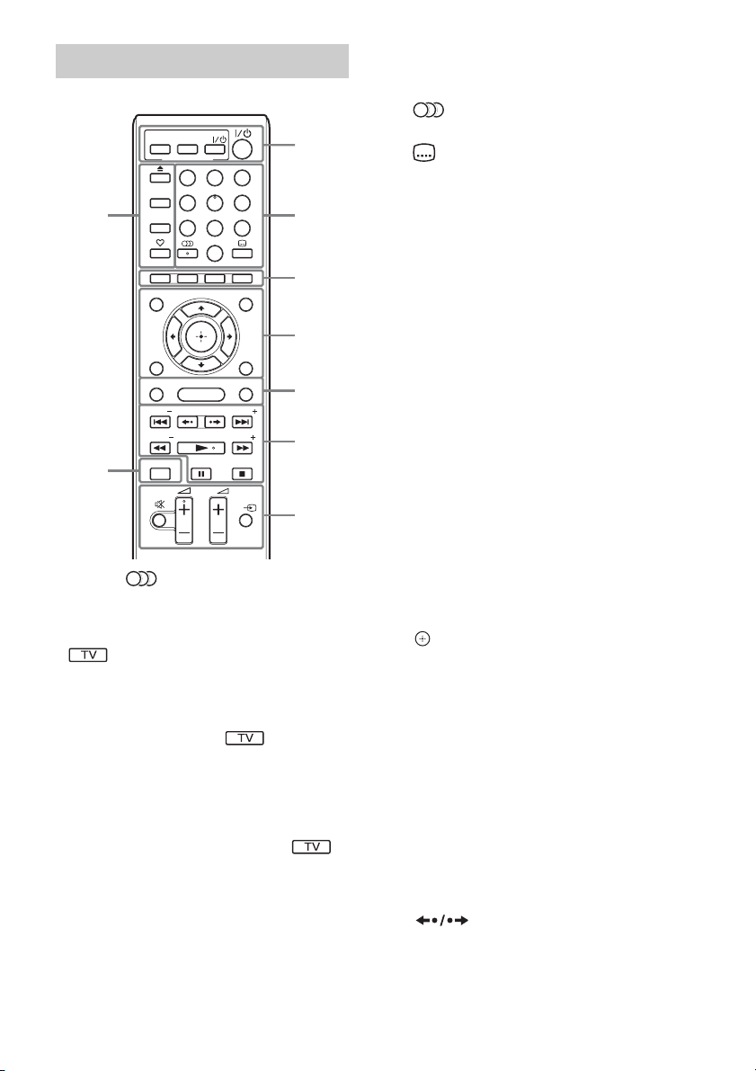
A THEATRE (page 47)
Switches to the optimum video mode for
watching movies automatically.
ONE-TOUCH PLAY (page 47)
Activates One-Touch Play.
TV "/1 (on/standby) (page 51)
Turns on the TV or sets it to standby mode.
"/1 (on/standby) (pages 25, 39)
Turns on the system or sets it to standby
mode.
1
2
3
4
5
6
7
B Number buttons (pages 40, 51)
Enters the title/chapter numbers, radio
frequencies, etc.
(audio) (pages 36, 37)
Selects the audio format/track.
(subtitle) (page 55)
Selects the subtitle language when
multilingual subtitles are recorded on a BDROM/DVD VIDEO.
D.TUNING (page 39)
Selects the radio frequencies.
C Color buttons (red/green/yellow/blue)
Short cut keys for selecting items on some
BD menus (can also be used for Java
interactive operations on BDs).
D TOP MENU
Opens or closes the BD’s or DVD’s Top
Menu.
POP UP/MENU
Opens or closes the BD-ROM’s Pop-up
Menu, or the DVD’s menu.
OPTIONS (page 34)
Displays the options menu on the TV
screen.
RETURN
Returns to the previous display.
C/X/x/c
Moves the highlight to a displayed item.
(ENTER)
Enters the selected item.
E FUNCTION (pages 26, 39)
Selects the playback source.
HOME (pages 25, 39, 41, 48, 49, 52)
Enters or exits the system’s home menu.
SOUND MODE (page 36)
Selects the sound mode.
F Playback operation buttons
See “Playback” (page 29).
./> (previous/next)
Skip to the previous/next chapter, track, or
file.
(replay/advance)
Briefly replay the current scenes for 10
seconds./Briefly fast forwards the current
scenes for 15 seconds.
11
GB

m/M (fast reverse/fast forward)
Fast reverse/fast forward the disc during
playback. Each time you press the button,
search speed changes.
Activates slow-motion play when pressed
for more than one second in pause mode.
Plays one frame at a time when pressed in
pause mode.
N (play)
Starts or re-starts playback (resume play).
Plays a slideshow when a disc containing
JPEG image files is inserted.
X (pause)
Pauses or re-starts playback.
x (stop)
Stops playback and remembers the stop
point (resume point). The resume point for
a title/track is the last point you played or
the last photo for a photo folder.
Radio operation buttons
See “Tuner” (page 39).
PRESET +/–
TUNING +/–
G (muting)
Turns off the sound temporarily.
2 (volume) +/– (page 39)
Adjusts the volume.
TV 2 (volume) +/–
Adjusts the TV volume.
TV t (TV input)
Switches the TV’s input source between the
TV and other input sources.
H DISPLAY (pages 29, 32)
Displays the playback information on the
TV screen.
When the function is “TUNER FM,”
changes the radio information in the front
panel display (European and Russian
models only).
When the function is “TV” or “SAT/
CABLE” and digital signals are input via
the DIGITAL IN jack, displays the stream
information in the front panel display.
I Z (open/close)
Opens or closes the disc tray.
SLEEP (page 51)
Sets the sleep timer.
SYSTEM MENU (pages 27, 35, 37, 39)
Enters the system menu.
(favorites)
Displays the Internet contents added to the
Favorites List. You can save 18 favorite
Internet contents.
12
GB
Getting Started
Step 1: Installing the System
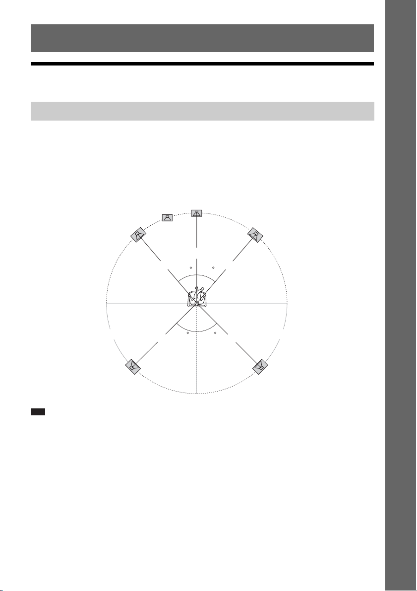
Positioning the speakers
For the best possible surround sound, place all speakers at the same distance from the listening position
(A). The distance can be between 0.0 to 7.0 meters.
If you cannot place the center speaker and surround speakers at the same distance as (A), place them
within 7.0 meters of the listening position.
Place the surround speakers to the rear of the listening position (B).
The subwoofer can be placed anywhere in the room.
Subwoofer
Center speaker
Getting Started
Front left speaker (L)
Front right speaker (R)
A
A
30 30
B B
Surround left speaker (L)
Note
• Use caution when placing the speakers and/or speaker stands attached to the speakers on a specially treated (waxed,
oiled, polished, etc.) floor, as staining or discoloration may result.
• Do not lean or hang on a speaker, as it may fall down.
45
A
45
AA
Surround right speaker (R)
13
GB

To add the optional surround back speakers
You can enjoy 7.1 surround sound by purchasing the Wireless Surround Speaker Kit (WAHT-SBP2,
optional). The optional product lineup differs depending on the area.
For the position of the surround back speakers, refer the illustration below (C).
Subwoofer
Center speaker
Getting Started
Note
• To use the surround back speakers, set [Surround Back] (page 49) in [Speaker Settings] to [Yes] while performing
the Easy Setup (page 25).
Front left speaker (L)
Surround left
speaker (L)
Surround back left speaker (L)
(optional)
30 30
45 45
CC
Front right speaker (R)
Surround right
speaker (R)
Surround back right speaker (R)
(optional)
Installing the speakers on a wall
Caution
• Contact a screw shop or installer regarding the wall material or screws to be used.
• Use screws that are suitable for the wall material and strength. As a plaster board wall is especially fragile, attach
the screws securely to a beam and fasten them to the wall. Install the speakers on a vertical and flat wall where
reinforcement is applied.
• Sony is not responsible for accidents or damage caused by improper installation, insufficient wall strength or
improper screw installation, natural calamity, etc.
Before installing the front speakers of BDV-E870 on a wall, you need to disassemble the speakers. You
can install the upper part of the speakers on a wall.
GB
14
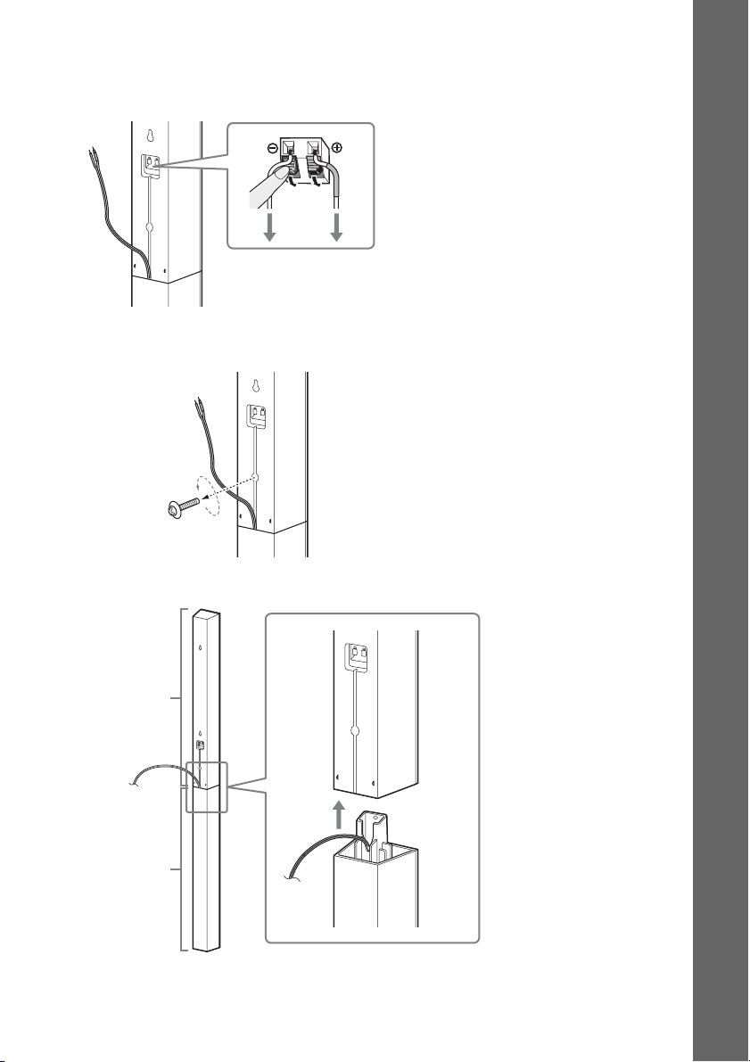
To disassemble the speaker
(Front speakers of BDV-E870 only)
1 Disconnect the speaker cords from the speaker.
Rear of the speaker
2 Remove the screw (pre-installed) at the rear of the speaker.
This screw is used when reassembling the speaker. Be sure not to lose the screw.
Getting Started
Screw
Rear of the speaker
3 Disassemble the speaker by lifting the upper part of the speaker.
Upper part
Lower part
Rear of the speaker
15
GB
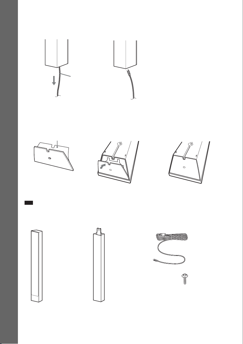
4 Pull out the speaker cord from the bottom of the lower part of the speaker.
The removed speaker cord is used when installing the speaker on a wall.
Lower part of the speaker
,
Getting Started
Speaker cord
5 Remove the protection paper from the speaker-bottom cover, then attach the speaker-
bottom cover to the bottom of the upper part of the speaker.
Bottom of the upper part of
Protection paper
the speaker
,,
Speaker-bottom cover
Note
• When removing the protection paper, pull it off via the section exposed by the notch in the speaker-bottom cover.
Fully-disassembled illustration
16
Upper part of
the speaker
GB
Lower part of
the speaker
Speaker cord
Screw
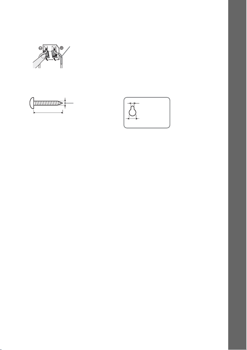
To install the speakers on a wall
Before installing the speakers on a wall, connect the speaker cord to the speaker.
Be sure to match the speaker cords to the appropriate terminals on the speakers: the speaker cord with
the color tube to 3, and the speaker cord without the color tube to #.
Color tube
Front left speaker (L): White
Front right speaker (R): Red
Center speaker: Green
Surround left speaker (L): Blue
Surround right speaker (R): Gray
1 Prepare screws (not supplied) that are suitable for the hole on the back of each speaker.
See the illustrations below.
Hole on the back of
4 mm
5 mm
the speaker
Getting Started
30 mm
10 mm
17
GB
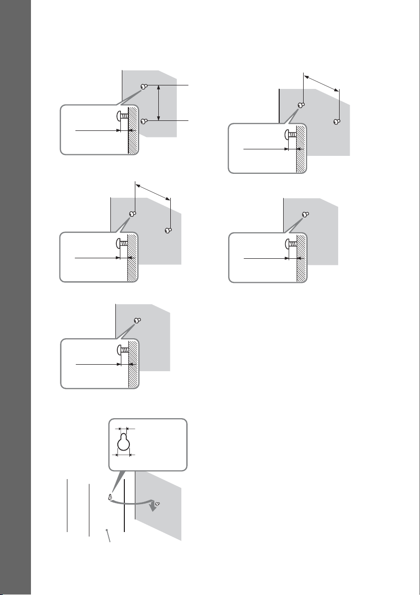
2 Fasten the screws to the wall.
BDV-E870
For the front speakers
Getting Started
8 to 10 mm
For the center speaker
304 mm
219 mm
BDV-E370
For the center speaker
219 mm
8 to 10 mm
For the other speakers
8 to 10 mm
For the surround speakers
8 to 10 mm
3 Hang the speakers on the screws.
5 mm
10 mm
Rear of the speaker
Hole on the back of
the speaker
8 to 10 mm
18
GB
Step 2: Connecting the System
For connecting the system, read the information on the following pages.
Do not connect the AC power cord (mains lead) of the unit to a wall outlet (mains) until all the other
connections are made.
Note
• When you connect another component with a volume control, turn down the volume of the other components to a
level where sound is not distorted.
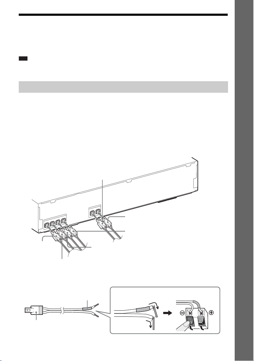
Connecting the speakers
The connector of the speaker cords and the color tube are color-coded depending on the type of speaker.
Connect the speaker cords to match the color of the SPEAKERS jacks of the unit.
Be sure to match the speaker cords to the appropriate terminals on the speakers: the speaker cord with
the color tube to 3, and the speaker cord without the color tube to #. Do not catch the speaker cord
insulation (rubber covering) in the speaker terminals.
To connect speaker cords to the unit
When connecting to the unit, insert the connector until it clicks.
Rear panel of the unit
Gray
(Surround right speaker (R))
Getting Started
S
R
E
K
A
E
P
S
L
R
U
S
R
R
U
S
R
E
K
A
E
P
S
R
E
T
N
E
C
R
FE
O
O
W
B
U
S
L
T
N
O
R
F
R
T
N
O
R
F
S
Blue
(Surround left speaker (L))
Green
(Center speaker)
Red
(Front right
speaker (R))
Purple
(Subwoofer)
White
(Front left speaker (L))
To connect speaker cords to the speaker
Color tube
Connector
(+)
(–)
Rear or bottom of the speaker
19
GB
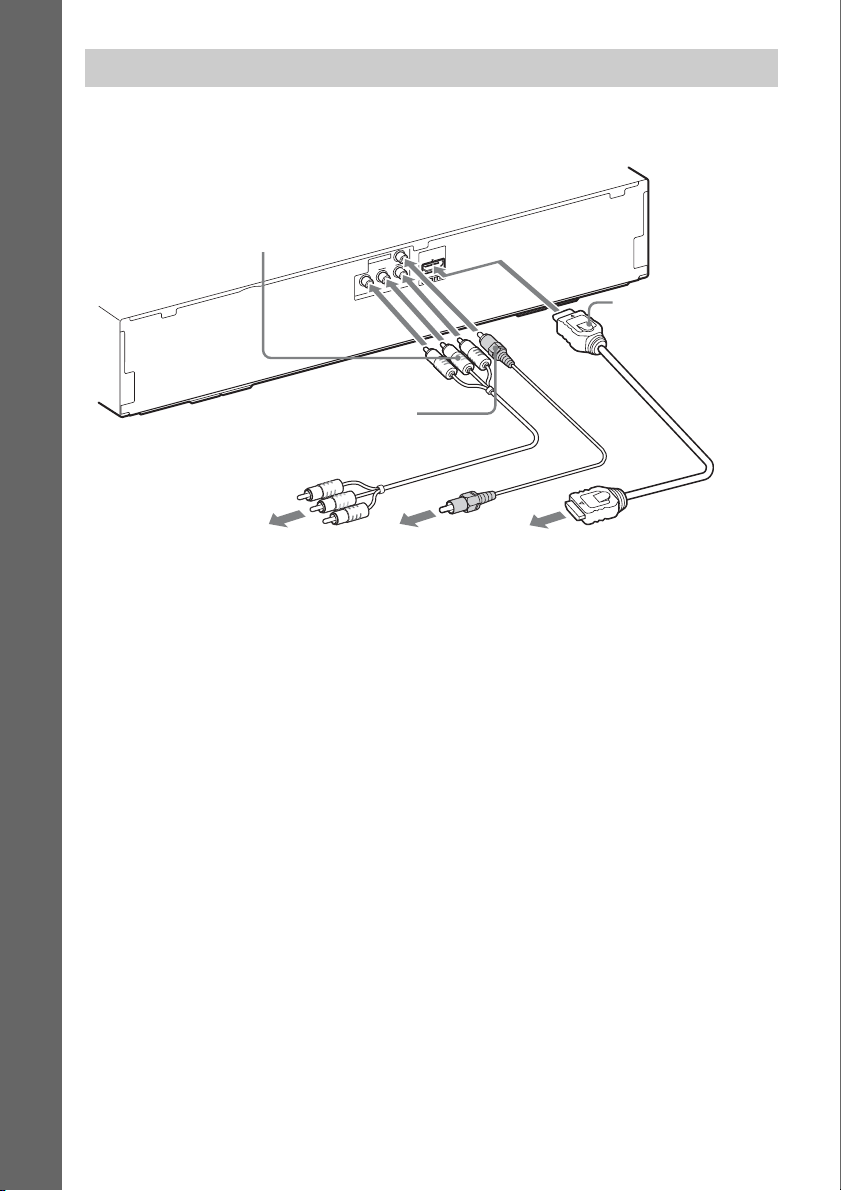
Connecting the TV (Video connection)
This connection sends a video signal to the TV.
Depending on the jacks on your TV, select the connection method.
Rear panel of the unit
Getting Started
B Component video
cable (not supplied)
T
U
O
O
E
ID
V
ARC
OUT
R
/ C
R
P
B
/ C
T
B
P
U
O
O
E
ID
V
Y
T
N
E
N
O
P
M
O
C
A HDMI cable*
C Video cord (supplied)
To the component
video input jacks of
the TV.
To the video input
jack of the TV.
To the HDMI IN jack
of the TV.
* The HDMI cable is supplied with Singapore, Thai, and Taiwan models only.
Method 1: HDMI cable (A) connection
If your TV has an HDMI jack, connect to the TV with an HDMI cable. Picture quality will be improved
compared to using the component video cable connection or the video cord connection.
When connecting with the HDMI cable, you need to select the type of output signal (page 53).
Method 2: Component video cable (B) connection
If your TV does not have an HDMI jack, but has component video input jacks, connect to the TV with
a component video cable. Picture quality will be improved compared to using the video cord
connection.
When connecting with the component video cable, you need to select the type of output signal (page
53).
Method 3: Video cord (C) connection
If you do not have an HDMI cable or a component video cable, temporarily make this connection.
GB
20
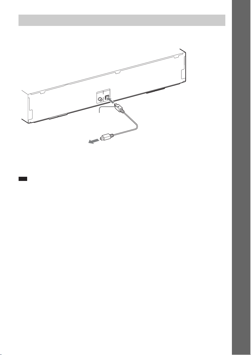
Connecting the TV (Audio connection)
This connection sends an audio signal to the unit from the TV. To listen to TV sound via the system,
perform this connection.
Rear panel of the unit
IO
D
AU
IN
IO
D
U
A
V
T
E
N
I
L
L
B
A
A
T
I
/C
G
T
I
A
D
S
N
I
L
A
T
I
IG
D
L
A
C
I
T
P
O
L
A
I
X
A
O
C
Digital optical cord (not
supplied)
To the digital optical out jack of
the TV.
With a digital audio connection, the system receives a Dolby Digital multiplex broadcast signal and
you can enjoy multiplex broadcast sound.
Note
• When you connect the TV and the unit with an audio cord, see “Connecting the other components” (page 22).
RL
Getting Started
About Audio Return Channel
If your TV is compatible with the Audio Return Channel function, an HDMI cable connection also
sends a digital audio signal from the TV. You do not need to make a separate audio connection for
listening to TV sound. For details of the Audio Return Channel function, see [Audio Return Channel]
(page 56).
21
GB

Connecting the other components
When you connect the system and other components to the TV, video signals from the system and the
components are sent to the TV, and audio signals from the components are sent to the system as
follows.
TV
Getting Started
System
Signal flow
: Video signal
: Audio signal
You can enjoy connected components via the system’s speakers.
• VCR or digital satellite receiver, etc. (not supplied), which has a digital coaxial output jack: D
• VCR, digital satellite receiver, PlayStation, or portable audio source, etc. (not supplied): E
Rear panel of the unit
To the digital coaxial out jack
of the VCR or digital satellite
receiver, etc.
D Digital coaxial cord
(not supplied)
V
T
E
L
IN
L
B
A
A
T
I
/C
T
IG
A
D
S
IN
L
A
T
I
G
I
D
L
A
C
I
T
P
O
L
A
I
X
A
O
C
IO
D
U
A
IN
IO
D
U
A
RL
E Audio cord
(not supplied)
To the audio out jacks of the VCR,
digital satellite receiver, PlayStation,
or portable audio source, etc.
22
GB

p
Connecting the antenna (aerial)
To connect the antenna (aerial)
Rear panel of the unit
5
7
L
IA
X
A
O
C
M
A
F
N
N
E
T
N
A
or
FM wire antenna (aerial)
(supplied)
Note
• Be sure to fully extend the FM wire antenna (aerial).
• After connecting the FM wire antenna (aerial), keep it as horizontal as possible.
Ti
• If you have poor FM reception, use a 75-ohm coaxial cable (not supplied) to connect the unit to an outdoor FM
antenna (aerial) as shown below.
Outdoor FM antenna (aerial)
Unit
Getting Started
COAXIAL
FM
75
ANTENNA
GB
23
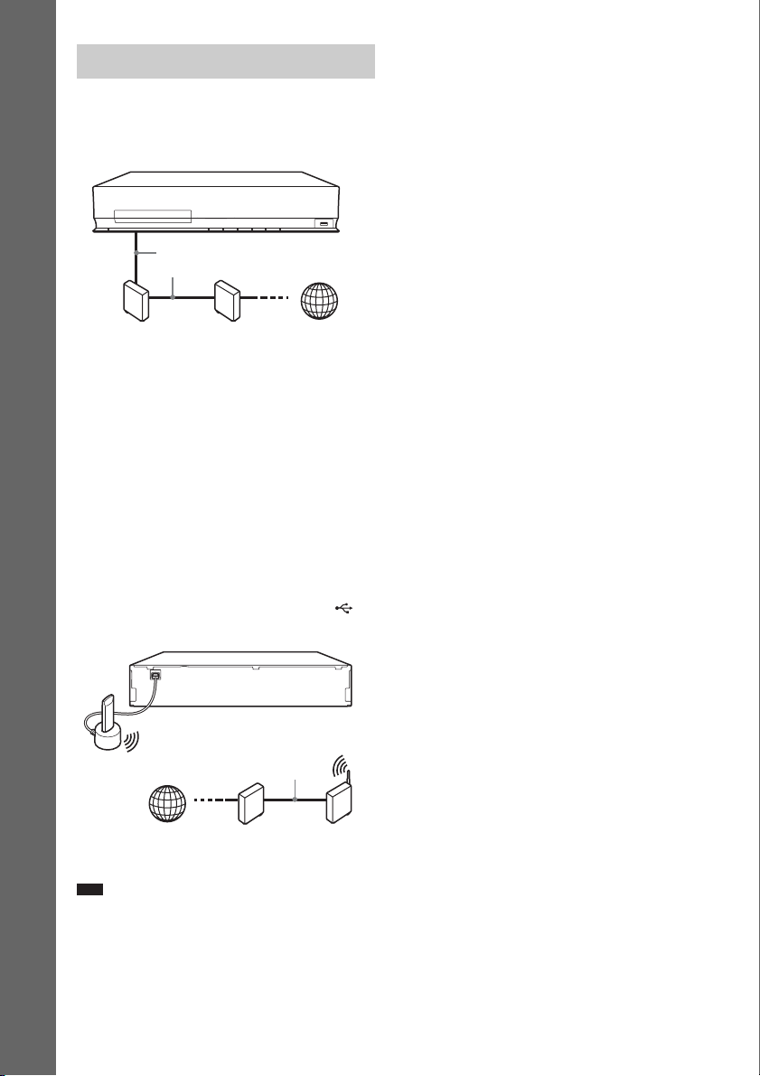
Connecting to the network
Wireless LAN Adapter and the wireless LAN router
closer to each other.
Wired Setup
Use a LAN cable to connect to the LAN (100)
terminal on the unit.
Getting Started
LAN cable
(not supplied)
Broadband
router
ADSL modem/
cable modem
USB Wireless Setup
Use a wireless LAN via the USB Wireless LAN
Adapter (Sony UWA-BR100* only) (not
supplied).
The USB Wireless LAN Adapter may not be
available in some regions/countries.
* As of January 2010.
Turn the unit off before connecting the
extension cable or inserting the USB Wireless
LAN Adapter. After inserting the USB Wireless
LAN Adapter to the base of the extension cable
and connecting the extension cable to the
(USB) port (front or rear), turn the unit on again.
VIDEO OUT
LAN(100)
ARC
Y
PB / CBPR / C
R
OUT
COMPONENT VIDEO OUT
SAT/CABLE
TV
SPEAKERS
DIGITAL IN
DIGITAL IN
SUR R SUR L
COAXIAL
OPTICAL
LAN cable
(not supplied)
ADSL modem/
cable modem
COAXIAL
FM
75
ANTENNA
USB
Wireless
LAN
Adapter
SPEAKERS
FRONT R
FRONT L
SUBWOOFER CENTER
Internet
Internet
EZW-T100
A. CAL MIC
AUDIO
ECM-AC2
AUDIO INRL
Wireless LAN
router
To set the network settings
For details, see [Network Settings] (page 57)
and follow the on-screen instructions to
complete the setup.
About wireless LAN security
Since communication via the wireless LAN
function is established by radio waves, the
wireless signal may be susceptible to
interception. To protect wireless
communication, this system supports various
security functions. Be sure to correctly
configure the security settings in accordance
with your network environment.
No Security
Although you can easily make settings, anyone
can intercept wireless communication or intrude
into your wireless network, even without any
sophisticated tools. Keep in mind that there is a
risk of unauthorized access or interception of
data.
WEP
WEP applies security to communications to
prevent outsiders from intercepting
communications or intruding into your wireless
network. WEP is a legacy security technology
that enables older devices, which do not support
TKIP/AES, to be connected.
WPA-PSK (TKIP), WPA2-PSK (TKIP)
TKIP is a security technology developed to
correct for the deficiencies of WEP. TKIP
assures a higher security level than WEP.
WPA-PSK (AES), WPA2-PSK (AES)
AES is a security technology that uses an
advanced security method that is distinct from
WEP and TKIP.
AES assures a higher security level than WEP or
TKIP.
Note
• The placement distance between the USB Wireless
LAN Adapter and your wireless LAN router differs
depending on the usage environment. If the system
cannot connect to the network or the network
connection is unstable, move the USB Wireless LAN
Adapter to a different position or place the USB
GB
24
 Loading...