

Page 1

Multi Channel AV
Receiver
3-289-204-42(3)
Operating Instructions
STR-DA2400ES
©2008 Sony Corporation
Page 2
WARNING
To reduce the risk of fire or electric
shock, do not expose this apparatus to
rain or moisture.
To reduce the risk of fire, do not cover the ventilation
opening of the apparatus with newspapers,
tablecloths, curtains, etc. Do not place the naked
flame sources such as lighted candles on the
apparatus.
To reduce the risk of fire or electric shock, do not
expose this apparatus to dripping or splashing, and
do not place objects filled with liquids, such as
vases, on the apparatus.
Do not install the appliance in a confined space, such
as a bookcase or built-in cabinet.
As the main plug is used to disconnect the unit from
the mains, connect the unit to an easily accessible
AC outlet. Should you notice an abnormality in the
unit, disconnect the main plug from the AC outlet
immediately.
Do not expose batteries or apparatus with batteryinstalled to excessive heat such as sunshine, fire or
the like.
For customers in Europe
Disposal of Old Electrical &
Electronic Equipment
(Applicable in the European
Union and other European
countries with separate
collection systems)
This symbol on the product or on its packaging
indicates that this product shall not be treated as
household waste. Instead it shall be handed over to
the applicable collection point for the recycling of
electrical and electronic equipment. By ensuring this
product is disposed of correctly, you will help
prevent potential negative consequences for the
environment and human health, which could
otherwise be caused by inappropriate waste
handling of this product. The recycling of materials
will help to conserve natural resources. For more
detailed information about recycling of this product,
please contact your local Civic Office, your
household waste disposal service or the shop where
you purchased the product.
Disposal of waste batteries
(applicable in the European
Union and other European
countries with separate
collection systems)
This symbol on the battery or on the packaging
indicates that the battery provided with this product
shall not be treated as household waste.
By ensuring these batteries are disposed of correctly,
you will help prevent potentially negative
consequences for the environment and human health
which could otherwise be caused by inappropriate
waste handling of the battery. The recycling of the
materials will help to conserve natural resources.
In case of products that for safety, performance or
data integrity reasons require a permanent
connection with an incorporated battery, this battery
should be replaced by qualified service staff only.
To ensure that the battery will be treated properly,
hand over the product at end-of-life to the applicable
collection point for the recycling of electrical and
electronic equipment.
For all other batteries, please view the section on
how to remove the battery from the product safely.
Hand the battery over to the applicable collection
point for the recycling of waste batteries. For more
detailed information about recycling of this product
or battery, please contact your local Civic Office,
your household waste disposal service or the shop
where you purchased the product.
Notice for the customer in the
countries applying EU Directives
The manufacturer of this product is Sony
Corporation, 1-7-1 Konan Minato-ku Tokyo, 1080075 Japan. The Authorized Representative for
EMC and product safety is Sony Deutschland
GmbH, Hedelfinger Strasse 61, 70327 Stuttgart,
Germany. For any service or guarantee matters
please refer to the addresses given in separate
service or guarantee documents.
GB
2
Page 3
About This Manual
• The instructions in this manual are for model
STR-DA2400ES. Check your model number by
looking at the lower right corner of the front panel.
In this manual, models of area code CEL is used
for illustration purposes unless stated otherwise.
Any difference in operation is clearly indicated in
the text, for example, “Models of area code CEK
only”.
• The instructions in this manual describe the
controls on the supplied remote. You can also use
the controls on the receiver if they have the same
or similar names as those on the remote.
• “Neural-THX” and “neural THX” introduced in
the Operating Instructions and displayed in the
display window and on the GUI menu screen mean
Neural-THX Surround.
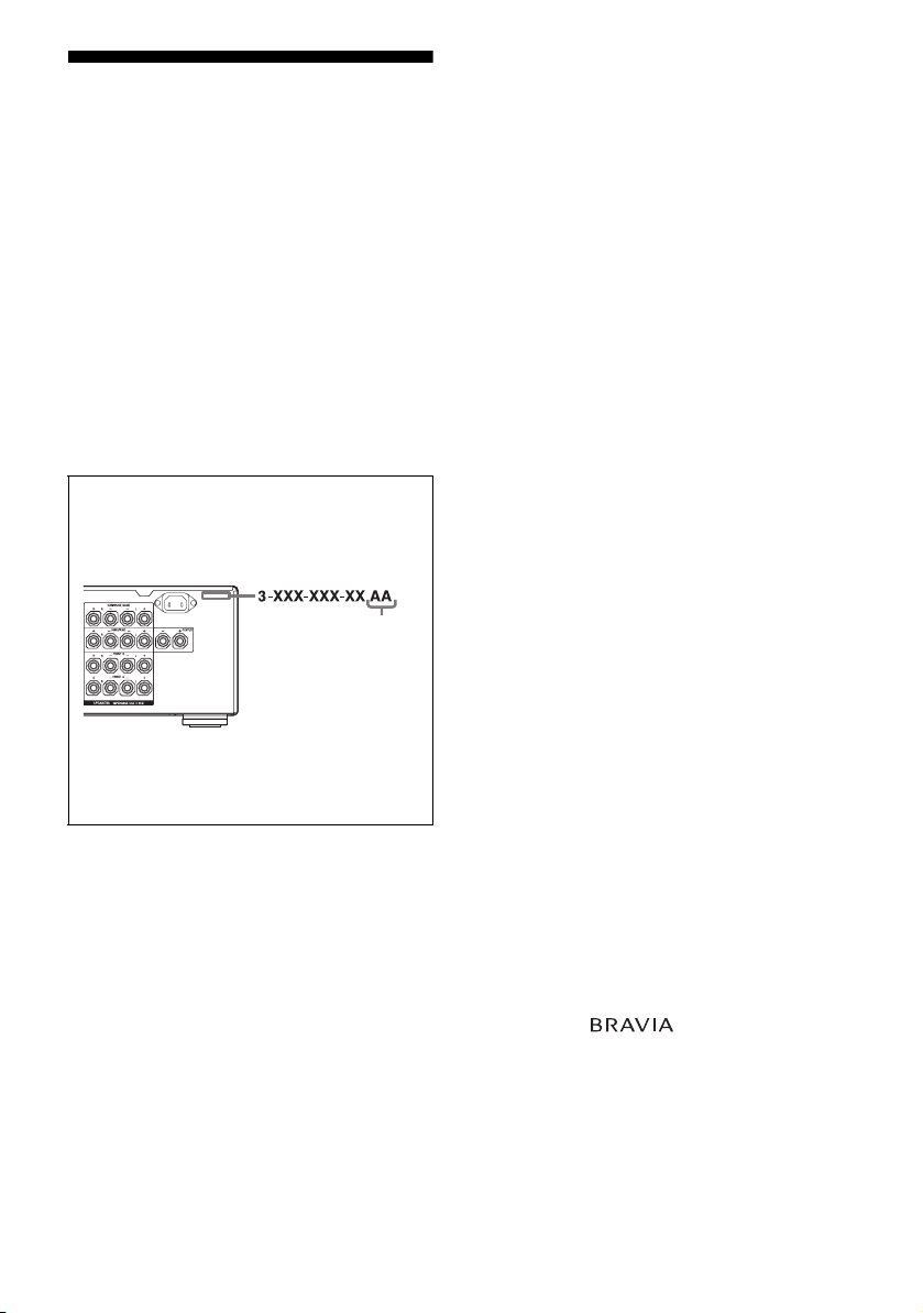
About area codes
The area code of the receiver you purchased is
shown on the upper right portion of the rear panel
(see the illustration below).
This receiver incorporates High-Definition
Multimedia Interface (HDMI™) technology.
HDMI, the HDMI logo and High-Definition
Multimedia Interface are trademarks or registered
trademarks of HDMI Licensing LLC.
This product is manufactured under license from
Neural Audio Corporation and THX Ltd. Sony
Corporation hereby grants the user a non-exclusive,
non-transferable, limited right of use to this product
under USA and foreign patent, patent pending and
other technology or trademarks owned by Neural
Audio Corporation and THX Ltd. “Neural
Surround”, “Neural Audio”, “Neural” and “NRL”
are trademarks and logos owned by Neural Audio
Corporation, THX is a trademark of THX Ltd.,
which may be registered in some jurisdictions. All
rights reserved.
The font type (Shin Go R) installed in this receiver
is provided by MORISAWA & COMPANY LTD.
These names are the trademarks of MORISAWA &
COMPANY LTD., and the copyright of the font also
belongs to MORISAWA & COMPANY LTD.
Area code
Any differences in operation, according to the area
code, are clearly indicated in the text, for example,
“Models of area code AA only”.
This receiver incorporates Dolby* Digital and Pro
Logic Surround and the DTS** Digital Surround
System.
* Manufactured under license from Dolby
Laboratories. Dolby, Pro Logic, Surround EX,
and the double-D symbol are trademarks of
Dolby Laboratories.
** Manufactured under license under U.S. Patent
#’s: 5,451,942; 5,956,674; 5,974,380; 5,978,762;
6,226,616; 6,487,535 & other U.S. and
worldwide patents issued & pending. DTS is a
registered trademark and the DTS logos,
Symbol, DTS-HD and DTS-HD Master Audio
are trademarks of DTS, Inc. © 1996-2007 DTS,
Inc. All Rights Reserved.
iPod is a trademark of Apple Inc., registered in the
U.S. and other countries.
All other trademarks and registered trademarks are
of their respective holders. In this manual, ™ and ®
marks are not specified.
The Bluetooth word mark and logos are owned by
the Bluetooth SIG, Inc. and any use of such marks by
Sony Corporation is under license.
Other trademarks and trade names are those of their
respective owners.
“M-crew Server” is a trademark of Sony
Corporation.
“x.v.Colour (x.v.Color)” and “x.v.Colour
(x.v.Color)” logo are trademarks of Sony
Corporation.
“BRAVIA” and are trademarks of Sony
Corporation.
GB
3
Page 4

Table of Contents
Getting Started
Description and location of parts ..................6
1: Installing the speakers ............................14
2: Connecting speakers ...............................16
3: Connecting the TV .................................18
4a: Connecting the audio components ........19
4b: Connecting the video components .......24
5: Connecting the antennas (aerials) ...........35
6: Preparing the receiver and the remote ....36
7: Operating the receiver using the GUI
(Graphical User Interface) .....................39
8: Setting the speakers ................................42
9: Calibrating the appropriate speaker settings
automatically (Auto Calibration) ...........44
Playback
Selecting a component ................................50
Listening to a Super Audio CD/CD ............52
Watching a DVD/Blu-ray Disc ................... 53
Enjoying video games ................................ 54
Watching video ...........................................55
Amplifier Operations
Settings for the audio
(Audio settings menu) ...........................56
Settings for the video
(Video settings menu) ............................57
Settings for HDMI
(HDMI settings menu) ...........................57
Enjoying Surround Sound
Enjoying a pre-programmed sound field ....58
Resetting sound fields to the initial
settings ...................................................64
Enjoying the surround effect at low volume
levels (NIGHT MODE) .........................65
Advanced Speakers Setting
Up
Adjusting the speaker settings manually .... 65
Adjusting the equalizer .............................. 71
Tuner Operations
Listening to FM/AM radio ......................... 72
Using the Radio Data System (RDS)
(Models of area code CEL, CEK, ECE
only) ...................................................... 75
Control for HDMI
Using the Control for HDMI function for
“BRAVIA” Sync ................................... 77
Preparing Control for HDMI function ....... 79
Watching a DVD (One-Touch Play) .......... 80
Enjoying the TV sound from the speakers
connected to the receiver
(System Audio Control) ........................ 81
Turning off the receiver with the TV
(System Power Off) .............................. 81
Other Operations
Converting analog video input signals ....... 82
Enjoying the DIGITAL MEDIA PORT
adapter (DMPORT) ............................... 82
Naming inputs ............................................ 86
Switching between digital and analog audio
(INPUT MODE) ................................... 87
Enjoying the sound/images from other
inputs ..................................................... 88
Changing the display ................................. 90
Using the sleep timer ................................. 94
Recording using the receiver ...................... 94
Using a bi-amplifier connection ................. 95
Operating without connecting to the TV ... 96
GB
4
Page 5

Using the Remote
Operating each component using the
remote ................................................. 105
Programming the remote .......................... 107
Clearing all the contents of the remote’s
memory ............................................... 111
Additional Information
Glossary ................................................... 112
Precautions ............................................... 115
Troubleshooting ....................................... 116
Specifications ........................................... 122
Index ......................................................... 124
GB
5
Page 6
Getting Started
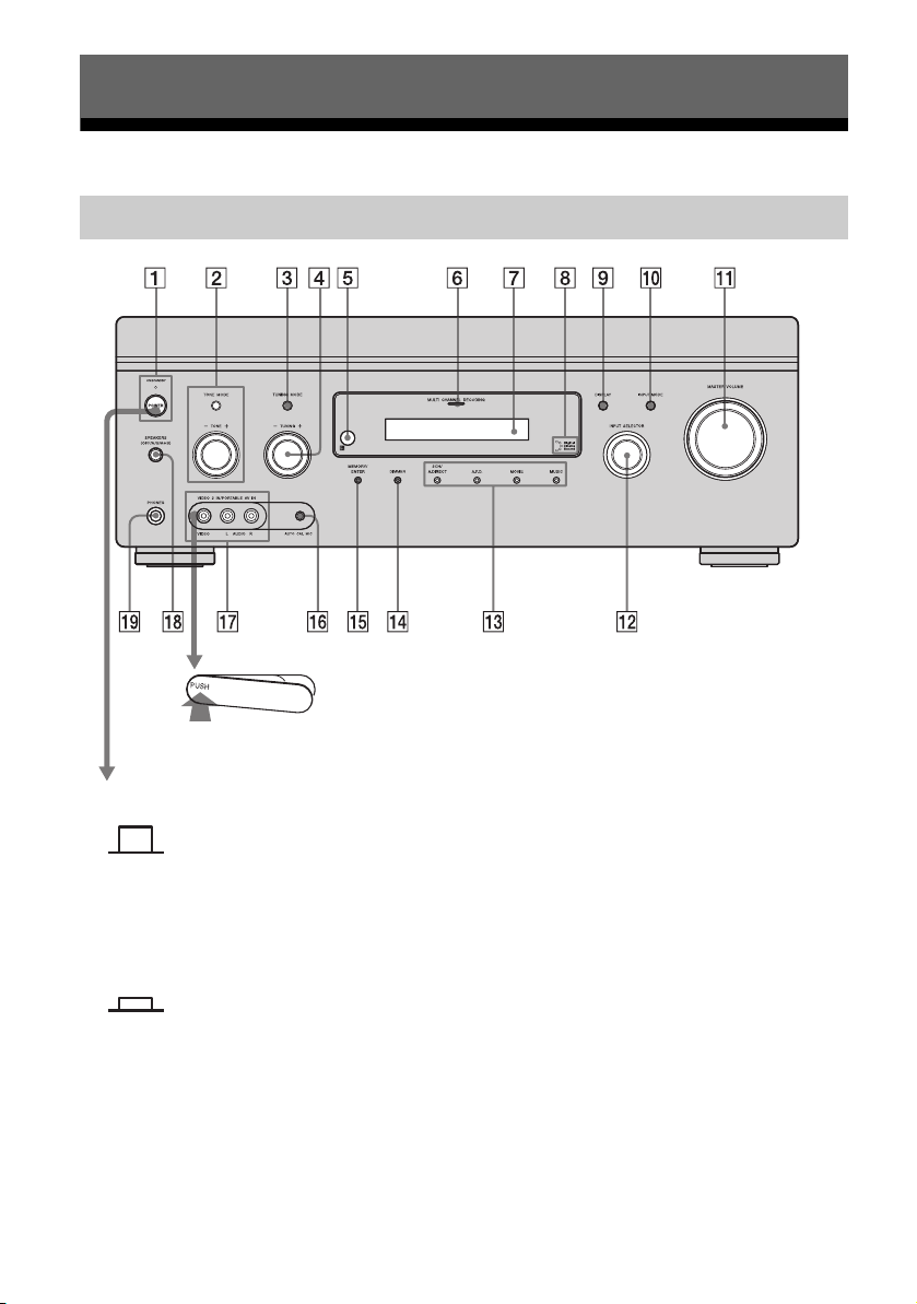
Description and location of parts
Front panel
To remove the cover
Press PUSH.
When you remove the cover, keep it out
of reach from children.
Status of the POWER button
x (Off)
The receiver is turned off (initial setting).
The ON/STANDBY lamp lights off.
Press POWER to turn the receiver on. You cannot
turn the receiver on using the remote.
x (On/Standby)
Press
?/1 on the remote to turn the receiver on or
set it to the standby mode.
When you press POWER on the receiver, the
receiver will be turned off.
GB
6
Page 7

Name Function
A POWER Press to turn the
receiver on or off.
ON/STANDBY
lamp
Lights up in green
when the receiver is
turned on. Lights up in
red when the receiver is
set to standby mode.
B TONE MODE Adjusts the tonal
TONE +/–
quality (bass/treble
level) of the front,
center and surround
speakers. Press TONE
MODE repeatedly to
select bass or treble
level, then turn TONE
+/– to adjust the level
(page 98).
C TUNING MODE Press to select the
tuning mode
(page 104, 105).
D TUNING +/– Turn to scan a station
(page 104, 105).
E Remote
sensor
F MULTI
CHANNEL
DECODING
Receives signals from
remote commander.
Lights up when multi
channel audio signals
are decoded.
lamp
G Display
window
The current status of
the selected component
or a list of selectable
items appears here
(page 91).
H Digital Cinema
Sound lamp
Lights up when a sound
field with DCS is
selected (page 63).
I DISPLAY Press repeatedly to
select information
displayed on the
display.
Name Function
J INPUT MODE Press to select the input
mode when the same
components are
connected to both
digital and analog
jacks.
K MASTER
VOLUME
Turn to adjust the
volume level of all
speakers at the same
time.
L INPUT
SELECTOR
Turn to select the input
source to play back.
M 2CH/A.DIRECT Press to select sound
A.F.D.
field (page 103, 104).
MOVIE
MUSIC
N DIMMER Press repeatedly to
adjust brightness of the
display.
O MEMORY/
ENTER
Press to store a station
or enter the selection
when selecting the
settings.
P AUTO CAL MIC
jack
Connects to the
supplied optimizer
microphone for the
Digital Cinema Auto
Calibration function
(page 45).
Q VIDEO 2 IN/
PORTABLE AV
IN jacks
Connect to a portable
audio/video component
such as a camcorder or
video game.
R SPEAKERS
(OFF/A/B/A+B)
Press to select the
speaker system
(page 44).
S PHONES jack Connects to
headphones.
Getting Started
GB
7
Page 8
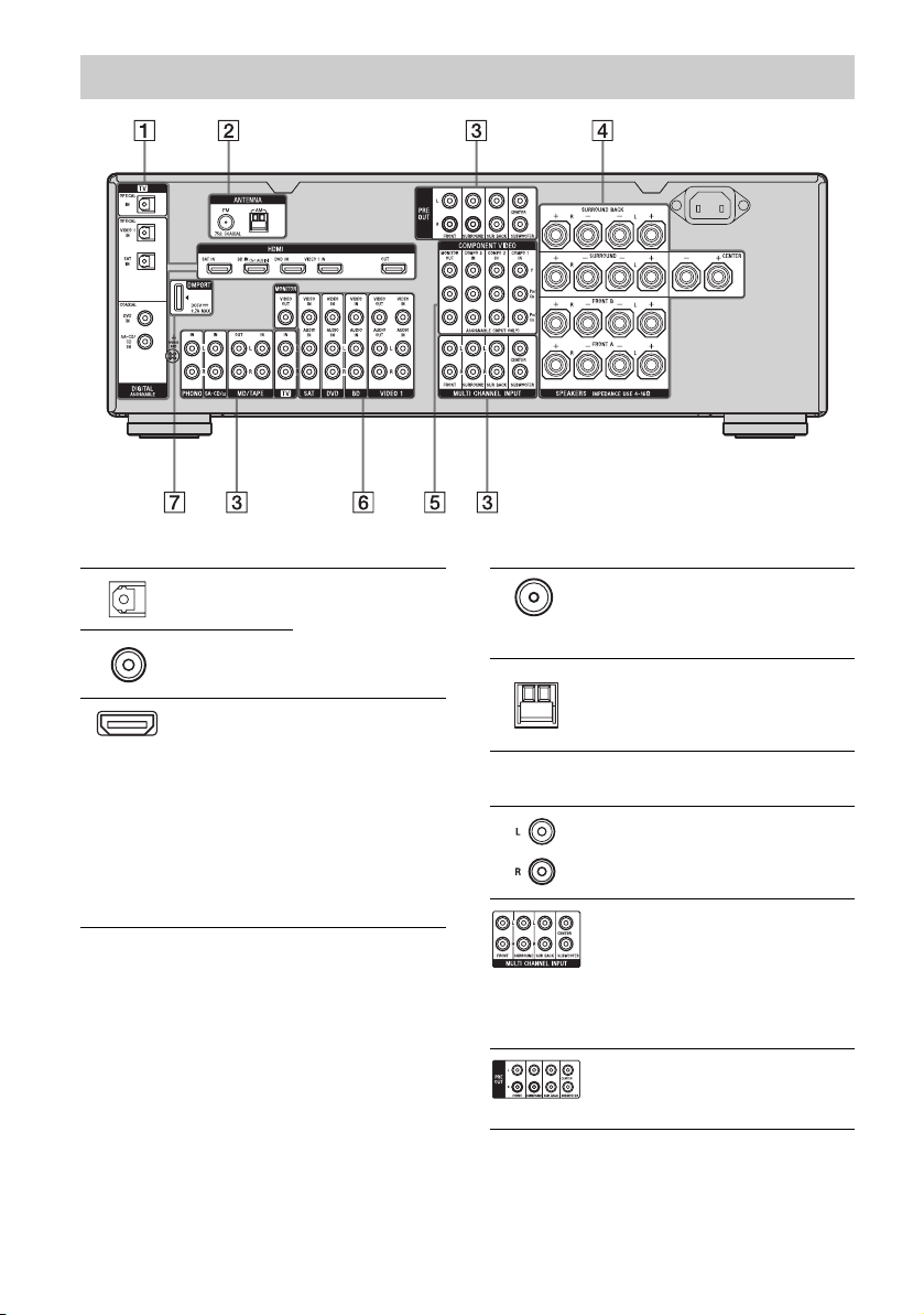
Rear panel
A DIGITAL INPUT/OUTPUT section
OPTICAL IN/
OUT jacks
COAXIAL IN
jacks
HDMI IN/
OUT* jacks
Connect to a DVD
player, etc. The
COAXIAL jack
provides a better
sound quality (page
18, 20, 29, 30).
Connect to a DVD
player, Blu-ray Disc
Player, or a satellite
tuner. The image is
output to a TV or a
projector while the
sound can be output
from a TV or/and
speakers connected
to this receiver (page
18, 26).
B ANTENNA section
FM ANTENNA
jack
AM
ANTENNA
jack
Connects to the FM
wire antenna (aerial)
supplied with this
receiver (page 35).
Connects to the AM
loop antenna (aerial)
supplied with this
receiver (page 35).
C AUDIO INPUT/OUTPUT section
AUDIO IN/
OUT jacks
MULTI
CHANNEL
INPUT jacks
PRE OUT
jacks
Connect to a Super
Audio CD player, etc
(page 18, 20, 23).
Connect to a Super
Audio CD player,
etc. with an analog
audio jack for 7.1
channel or 5.1
channel sound (page
22).
Connect to an
external power
amplifier.
GB
8
Page 9
D SPEAKERS section
Connects to speakers
(page 16).
E COMPONENT VIDEO INPUT/
OUTPUT section
Y, PB/CB, PR/
C
IN/OUT*
R
jacks
Connect to a DVD
player, TV, or a
satellite tuner etc.
(page 18, 28-30).
F VIDEO/AUDIO INPUT/OUTPUT
section
AUDIO IN/
OUT jacks
VIDEO IN/
OUT* jacks
G DMPORT
* You can watch the selected input image when you
connect the MONITOR OUT or HDMI OUT jack
to a TV (page 18). You can operate this receiver
using a GUI (Graphical User Interface) (page 39).
Connect to a VCR or
a DVD player etc.
(page 18, 29, 30, 31).
Connects to a
DIGITAL MEDIA
PORT adapter
(page 20).
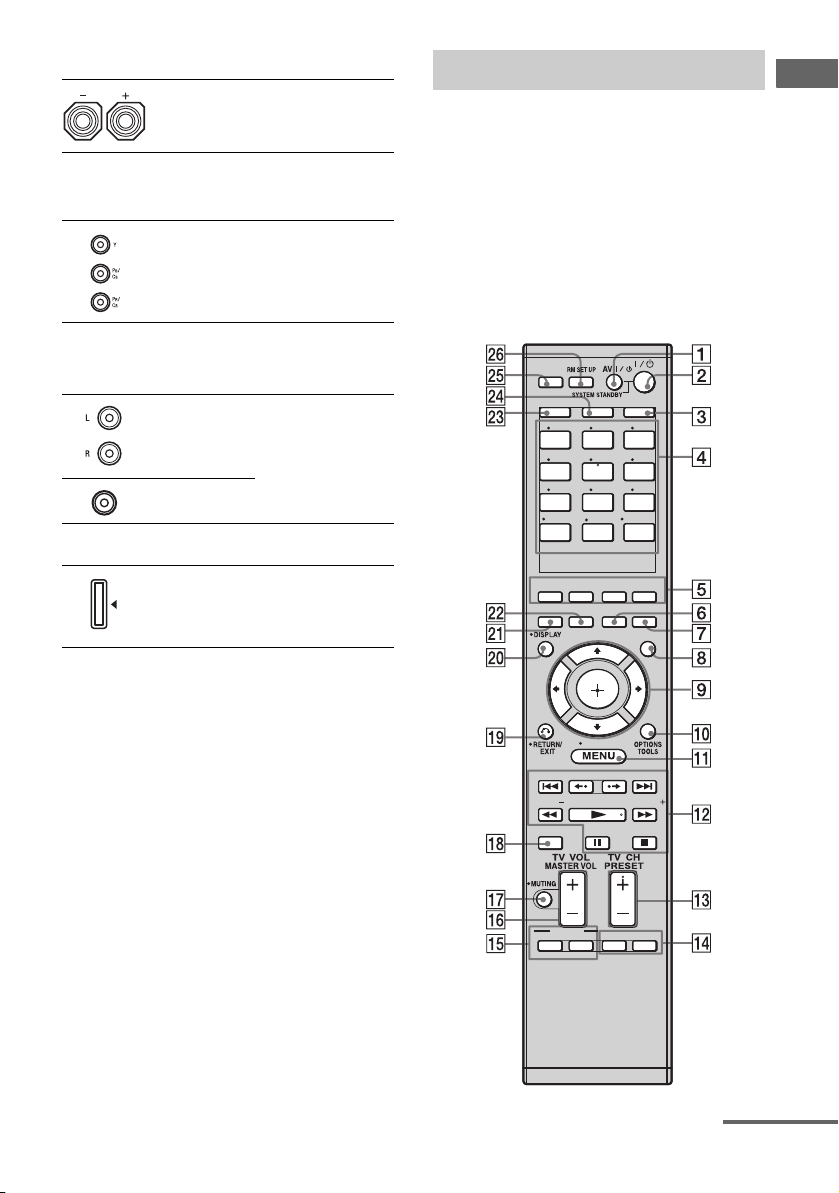
Remote commander
You can use the supplied remote to operate the
receiver and to control the Sony audio/video
components that the remote is assigned to
operate.
You can also program the remote to control
non-Sony audio/video components. For
details, see “Programming the remote”
(page 107).
RM-AAP024
THEATRE
SHIFT
123
VIDEO 1
456
DVD TV
789
MD/
TAPE
-/--
PHONO
CLEAR/>10
2CH/
A.DIRECT
A.F.D.
INPUT
MODERESOLUTION
VIDEO 2
SAT
SA-CD/
CD
0/10
MULTI IN
HOME
AMPTV
BD
TUNER
ENT/MEM
DMPORT
MUSICMOVIE
NIGHT
MODESLEEP
GUI
MODE
Getting Started
TUNING
DISC SKIP
BD/DVD
TOP MEN U
TV INPUT WIDE
MENU
TUNING
D.TUNING
F1 F2
continued
GB
9
Page 10

Name Function
A AV ?/1
(on/standby)
B ?/1
(on/standby)
C AMP Press to enable the receiver
D Input
buttons
Press to turn on or off the audio/
video components that the
remote is programmed to
operate.
To turn the TV on or off, press
TV (X) and then press AV
?/1.
If you press ?/1 (B) at the
same time, it will turn off the
receiver and other Sony
components (SYSTEM
STANDBY).
Note
The function of the AV ?/1
switch changes automatically
each time you press the input
buttons (D).
Press to turn the receiver on or
set it to standby mode.
To turn off all Sony
components, press ?/1 and AV
?/1 (A) at the same time
(SYSTEM STANDBY).
Saving the power in standby
mode.
When “Control for HDMI”
(page 79) is set to “OFF”.
operation (page 96).
Press one of the buttons to
select the component you want
to use. When you press any of
the input buttons, the receiver
turns on. The buttons are
factory assigned to control Sony
components (page 50). You can
program the remote to control
non-Sony components
following the steps in
“Programming the remote” on
page 107.
Name Function
Numeric
buttons
(number 5
ENT/MEM Press SHIFT (W) and then
CLEAR Press SHIFT (W) and then
-/-- Press SHIFT (W) and then
Press SHIFT (W) and then
press numeric buttons to
a)
)
– preset/tune to preset stations.
– select track numbers of the
CD player, VCD player, LD
player, DVD player, MD
deck, DAT deck, or tape
deck. Press 0/10 to select
track number 10.
– select channel numbers of
the VCR, satellite tuner, Bluray disc player, PSX, DVD/
VHS COMBO, or DVD/
HDD COMBO.
Press TV (X), and then press
the numeric buttons to select the
TV channels.
press ENT/MEM to
– enter the value after selecting
a channel, disc or track using
the numeric buttons of the
VCR, CD player, VCD
player, LD player, MD deck,
DAT deck, tape deck,
satellite tuner, Blu-ray disc
player, or PSX.
– store a station during tuner
operation.
To enter the value of Sony TV,
press TV (X) and then press
ENT/MEM.
press CLEAR to
– clear a mistake when you
press the incorrect numeric
button of the DVD player,
Blu-ray disc player, PSX,
satellite tuner, DVD/VHS
COMBO, or DVD/HDD
COMBO.
– return to continuous
playback, etc. of the satellite
tuner or DVD player.
press -/-- to select the channel
entry mode, either one or two
digit of the VCR or satellite
tuner.
To select the channel entry
mode of the TV, press TV (X)
and then press -/--.
10
GB
Page 11
Name Function
>10 Press SHIFT (W) and then
E 2CH/
A.DIRECT
A.F.D.
MOVIE
MUSIC
F SLEEP Press to activate the Sleep
G NIGHT
MODE
H GUI MODE Press to display the GUI menu
I
,
V/v/B/b
J OPTIONS
TOOLS
press >10 to
– select track numbers over 10
of the CD player, VCD
player, LD player, MD deck,
tape deck, TV, VCR, or
satellite tuner.
– select channel numbers of
the Digital CATV terminal.
Press to select a sound field
(page 103, 104).
Timer function and the duration
which the receiver turns off
automatically.
Press to activate the Night
Mode function (page 65).
on the TV screen.
After pressing AMP (C), press
HOME/MENU (K) for
receiver operation, then press V/
v/B/b to select the settings.
After pressing BD/DVD TOP
MENU (O) or BD/DVD
MENU (O), press V/v/B/b to
select the settings, and then
press to enter the selection.
Press also to enter the
selection of the receiver, VCR,
satellite tuner, DVD player,
Blu-ray disc player, PSX, DVD/
VHS COMBO, or DVD/HDD
COMBO.
Press to display and select items
from the option menus for
receiver, DVD player, Blu-ray
Disc Player, Satellite tuner and
PSX.
Press TV (X) and then
press TOOLS to display the
options of Sony TV.
Name Function
K HOME/
MENU
L ./>
m/M
a)b)
N
b)
X
b)
x
Press to display the menus of
the receiver, VCR, DVD player,
satellite tuner, Blu-ray disc
player, PSX, DVD/VHS
COMBO, or DVD/HDD
COMBO on the TV screen.
Then, use V/v/B/b and to
perform menu operations.
To display the menus of Sony
TV, press TV (X) and then
press HOME/MENU.
b)
Press to skip tracks of the VCR,
CD player, VCD player, LD
player, DVD player, MD deck,
DAT deck, tape deck, Blu-ray
disc player, PSX, DVD/VHS
COMBO, or DVD/HDD
COMBO.
b)
Press to
– search tracks in the forward/
backward direction of the CD
player, VCD player, DVD
player, LD player, MD deck,
Blu-ray disc player, PSX,
DVD/VHS COMBO, or
DVD/HDD COMBO.
– fast forward/rewind of the
VCR, DAT deck, or tape
deck.
Press to start playback of the
VCR, CD player, VCD player,
LD player, DVD player, MD
deck, DAT deck, tape deck,
Blu-ray disc player, PSX, DVD/
VHS COMBO, or DVD/HDD
COMBO.
Press to pause playback or
recording of the VCR, CD
player, VCD player, LD player,
DVD player, MD deck, DAT
deck, tape deck, Blu-ray disc
player, PSX, DVD/VHS
COMBO, or DVD/HDD
COMBO. (Also starts recording
with components in recording
standby.)
Press to stop playback of the
VCR, CD player, VCD player,
LD player, DVD player, MD
deck, DAT deck, tape deck,
Blu-ray disc player, PSX, DVD/
VHS COMBO, or DVD/HDD
COMBO.
Getting Started
continued
11
GB
Page 12

Name Function
TUNING +/– Press to scan a station.
D.TUNING Press to enter direct tuning
b
B
•/•
M TV CH +
PRESET
a)
+
/–
N F1, F2 Press F1 or F2 to select a
O BD/DVD
TOP MENU
BD/DVD
MENU
TV INPUT Press TV (X) and then press
WIDE Press TV (X) and then press
P
TV VOL
MASTER
VOL +/ –
mode.
Press to replay the previous
scene or fast forward the current
scene of the DVD player, Bluray disc player, DVD/VHS
COMBO, or DVD/HDD
COMBO.
a)
/– Press TV (X) and then press
TV CH +/– to select preset TV
channels.
Press to
– select preset stations.
– select preset channels of the
VCR, satellite tuner, Blu-ray
disc player, DVD player,
DVD/VHS COMBO, or
DVD/HDD COMBO.
component.
• DVD/HDD COMBO
F1: HDD mode
F2: DVD mode
• DVD/VHS COMBO
F1: DVD mode
F2: VHS mode
Press to display the menu or onscreen guide of the DVD or
Blu-ray disc on the TV screen.
Then, use V/v/B/b and to
perform menu operations.
Press to display the menu of the
DVD or Blu-ray disc on the TV
screen. Then, use V/v/B/b and
to perform menu
operations.
TV INPUT to select the input
signal (TV input or video
input).
WIDE to select the wide picture
mode.
+/– Press TV (X) and then press
TV VOL +/– to adjust the TV
volume level.
Press to adjust the volume level
of all speakers at the same time.
Name Function
Q MUTING Press to turn off the sound
R DISC SKIP Press to skip disc of the CD
S RETURN/
EXIT O
T DISPLAY Press to select information
U
RESOLUTION
V INPUT
MODE
W SHIFT Press to light up the buttons. It
temporarily. Press MUTING
again to restore the sound.
Press TV (X), and then press
MUTING to activate the TV’s
muting function.
player, VCD player, DVD
player, or MD deck (multi-disc
changer only).
Press to
– return to the previous menu.
– exit the menu while the menu
or on-screen guide of the
VCD player, LD player,
DVD player, Blu-ray disc
player, PSX, DVD/VHS
COMBO, or satellite tuner is
displayed on the TV screen.
To return to the previous menu
of Sony TV, press TV (X) and
then press RETURN/EXIT O.
displayed on the display
window or TV screen of the
VCR, VCD player, LD player,
DVD player, CD player, MD
deck, Blu-ray disc player, PSX,
satellite tuner, DVD/ VHS
COMBO, or DVD/HDD
COMBO.
To select information of Sony
TV, press TV (X) and then
press DISPLAY.
Press repeatedly to change the
resolution of signals output
from the HDMI OUT or
COMPONENT VIDEO
MONITOR OUT jack
(page 82).
Press to select the input mode
when the same components are
connected to both digital and
analog jacks (page 87).
changes the remote button
function to activate the buttons
with pink printing.
12
GB
Page 13
Name Function
X TV Press to light up the button. It
Y THEATRE Press to enjoy optimal image
Z RM SET UP Press to set up the remote.
a)
The number 5, TV CH +, PRESET + and N
buttons have tactile dots. Use the tactile dots as
references when operating the receiver.
b)
See the table on page 106 for information on the
buttons that you can use to control each
component.
changes the remote key
function to activate the buttons
with yellow printing. It also
activate the DISPLAY (T),
OPTIONS TOOLS (J),
HOME/MENU (K),
RETURN/EXIT O (S),
(I), and V/v/B/b (I) buttons
to perform menu operations for
Sony TVs only.
suited for movies and to output
the sound from the speakers
connected to this receiver
automatically.
Note
This button will only function if
your TV is compatible with
Theater Mode. For details, refer
to the operating instructions
supplied with the TV.
Notes
• Some functions explained in this section may not
work depending on the model.
• The above explanation is intended to serve as an
example only. Therefore, depending on the
component, the above operation may not be
possible or may operate differently than described.
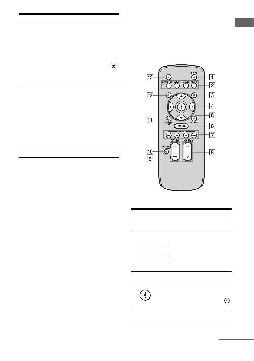
RM-AAU039
This remote can only be used to operate the
receiver. You can control the main functions of
the receiver with simple operations using this
remote.
SLEEP
DISPLAY
Name Function
A ?/1 (on/
standby)
B 2CH/
A.DIRECT
A.F.D.
MOVIE
MUSIC
C GUI MODE Press to display the GUI menu
D
V/v/B/b
E OPTIONS Press to display and select items
Press to turn a receiver on or off.
Press to select sound field
(page 103, 104).
on the TV screen.
After pressing GUI MODE
(3), press V/v/B/b to select
the menu items. Then press
to enter the selection.
from option menus.
GUI MODE
Getting Started
continued
13
GB
Page 14
Name Function
F MENU Press to display the menu to
G DMPORT Press to operate component
N Starts play.
x Stops play.
./> Skips tracks.
H INPUT
SELECTOR
I MASTER
VOLUME +/–
J MUTING Press to turn off the sound
K RETURN/
EXIT O
L DISPLAY Press to select information
M SLEEP Press to activate the sleep timer
operate the receiver.
connected to the DIGITAL
MEDIA PORT adapter
(page 50).
Press to select the input source
to play back.
Press to adjust the volume level.
temporarily. Press the button
again to restore the sound.
Press to return to the previous
menu or exit the menu.
displayed in the display
window.
function and the duration which
the receiver turns off
automatically (page 94).
1: Installing the speakers
This receiver allows you to use a 7.1 channel
system (7 speakers and one subwoofer).
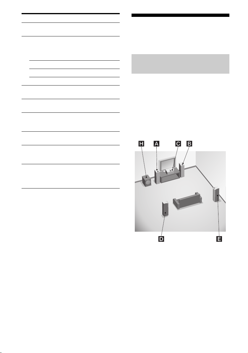
Enjoying a 5.1/7.1 channel
system
To fully enjoy theater-like multi channel
surround sound requires five speakers (two
front speakers, a center speaker, and two
surround speakers) and a subwoofer (5.1
channel system).
Example of a 5.1 channel
speaker system configuration
14
AFront speaker (left)
BFront speaker (right)
CCenter speaker
DSurround speaker (left)
ESurround speaker (right)
HSubwoofer
GB
Page 15
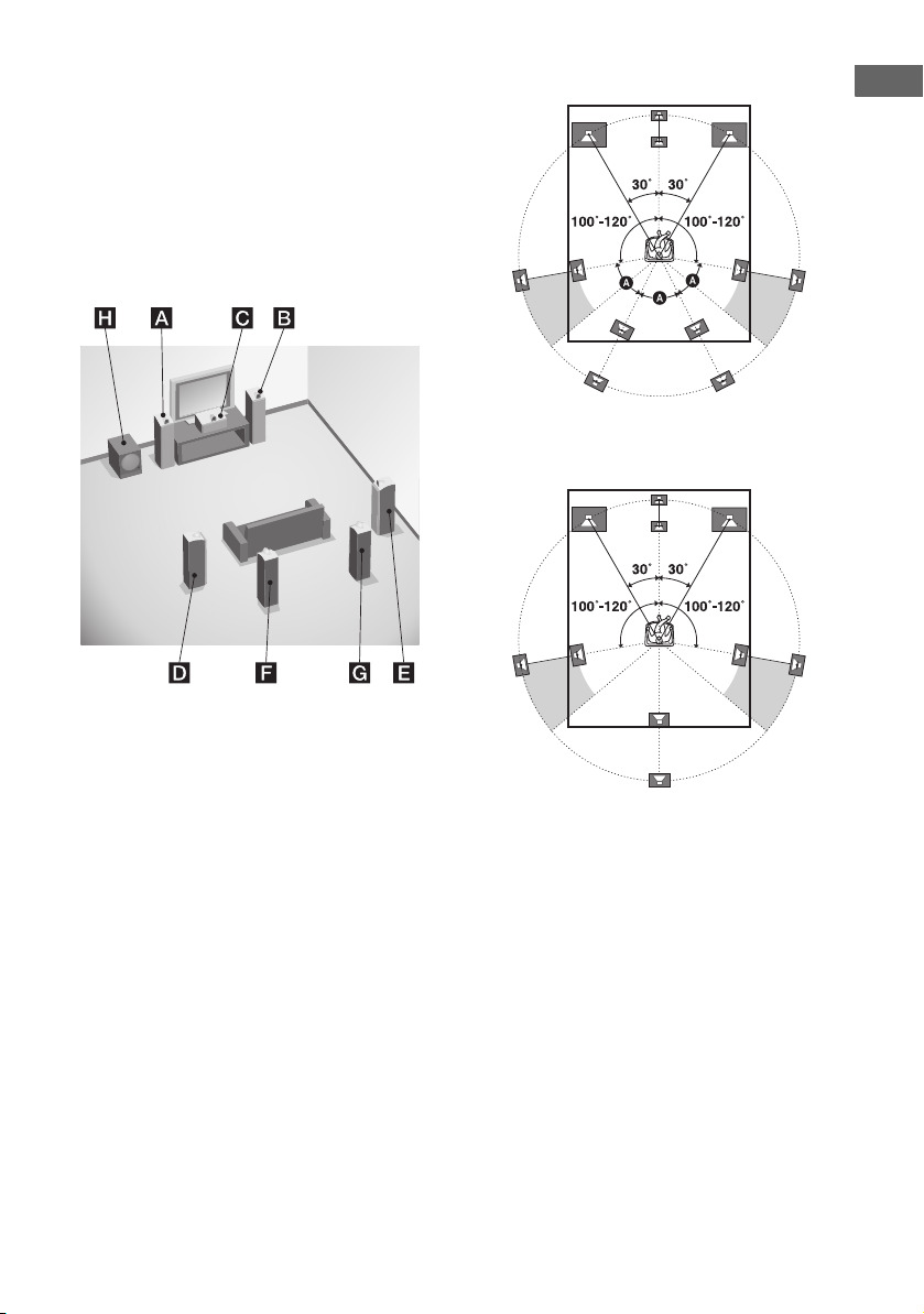
You can enjoy high fidelity reproduction of
DVD software recorded sound in the Surround
EX format if you connect one additional
surround back speaker (6.1 channel system) or
two surround back speakers (7.1 channel
system.)
Example of a 7.1 channel
speaker system configuration
Tips
• The angle A should be the same.
Getting Started
• When you connect a 6.1 channel speaker system,
place the surround back speaker behind the
listening position.
AFront speaker (left)
BFront speaker (right)
CCenter speaker
DSurround speaker (left)
ESurround speaker (right)
FSurround back speaker (left)
GSurround back speaker (right)
HSubwoofer
• Since the subwoofer does not emit highly
directional signals, you can place it wherever you
want.
15
GB
Page 16
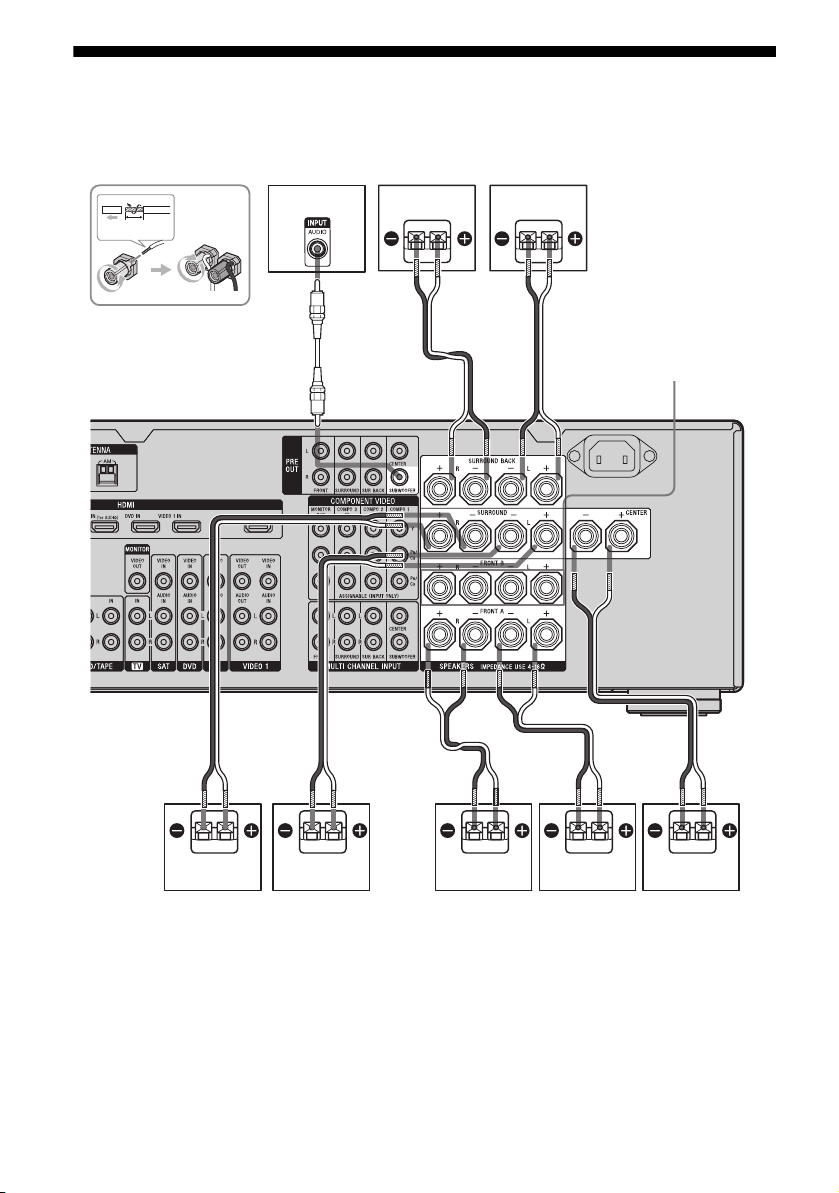
2: Connecting speakers
Before connecting cords, make sure to
disconnect the AC power cord (mains lead).
10 mm
H
G
F
BA
SPEAKERS FRONT
B terminals
a)
AAA
D
A Speaker cords (not supplied)
B Monaural audio cord (not supplied)
AFront speaker A (left)
BFront speaker A (right)
CCenter speaker
DSurround speaker (left)
GB
16
B
ACE
ESurround speaker (right)
FSurround back speaker (left)
GSurround back speaker (right)
HSubwoofer
c)
b)
b)
Page 17

a)
If you have an additional front speaker
system, connect them to the SPEAKERS
FRONT B terminals. You can select the front
speaker system you want to use with the
SPEAKERS (OFF/A/B/A+B) button on the
front panel (page 44).
b)
If you connect only one surround back
speaker, connect it to the SPEAKERS
SURROUND BACK L terminals.
c)
When you connect a subwoofer with an auto
standby function, turn off the function when
watching movies. If the auto standby
function is set to on, it turns to standby mode
automatically based on the level of the input
signal to a subwoofer, then sound may not be
output.
Notes
• When you connect all the speakers with a nominal
impedance of 8 ohms or higher, set “Speaker
Impedance” in the Speaker settings menu to “8
ohms”. In other connections, set it to “4 ohms”. For
details, see “8: Setting the speakers” (page 42).
• Before connecting the AC power cord (mains
lead), make sure that metallic wires of the speaker
cords are not touching each other between the
SPEAKERS terminals.
Tip
To connect certain speakers to another power
amplifier, use the PRE OUT jacks. The same signal
is output from both the SPEAKERS terminals and
the PRE OUT jacks. For example, if you want to
connect just the front speakers to another amplifier,
connect that amplifier to the PRE OUT FRONT L
and R jacks.
Getting Started
17
GB
Page 18
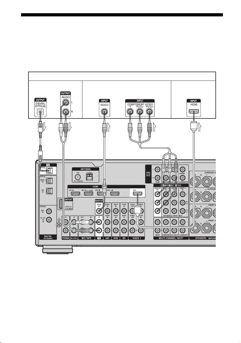
3: Connecting the TV
You can watch the selected input image when
you connect the MONITOR OUT or HDMI
OUT jack to a TV. You can operate this
receiver using a GUI (Graphical User
Interface).
Audio signals
Video signals Audio/ Video
AB
It is not necessary to connect all the cables.
Connect audio and video cords according to
the jacks of your components.
Before connecting cords, make sure to
disconnect the AC power cord (mains lead).
TV
signals
DEC
A Optical digital cord (not supplied)
B Audio cord (not supplied)
C Video cord (not supplied)
D Component video cord (not supplied)
E HDMI cable (not supplied)
We recommend that you use a Sony HDMI cable.
GB
18
Page 19

Notes
• Be sure to turn on the receiver when the video and
audio signals of a playback component are being
output to a TV via the receiver. If the power supply
of the receiver is not turned on, neither video nor
audio signals will be transmitted.
• When connecting optical digital cords, insert the
plugs straight in until they click into place.
• Do not bend or tie optical digital cords.
• Depending on the status of the connection between
the TV and the antenna (aerial), the image on the
TV screen may be distorted. In this case, place the
antenna (aerial) farther away from the receiver.
Tips
• The receiver has a video conversion function. For
details, see “Notes on converting video signals”
(page 33).
• The sound of the TV is output from the speakers
connected to the receiver if you connect the audio
output jack of the TV to the TV IN jacks of the
receiver. In this configuration, set the sound output
jack of the TV to “Fixed” if it can be switched
between either “Fixed” or “Variable”.
• All the digital audio jacks are compatible with
32 kHz, 44.1 kHz, 48 kHz, and 96 kHz sampling
frequencies.
4a: Connecting the audio components
How to hook up your
components
This section describes how to hook up your
components to this receiver. Before you begin,
refer to “Component to be connected” below
for the pages which describe how to connect
each component.
After hooking up all your components,
proceed to “5: Connecting the antennas
(aerials)” (page 35).
Component to be connected Page
Super Audio CD
player, CD player
MD deck, Tape deck,
Analog disc turntable
DIGITAL MEDIA PORT adapter 20
Notes
• Before connecting cords, make sure to disconnect
the AC power cord (mains lead).
• When connecting optical digital cords, insert the
plugs straight in until they click into place.
• Do not bend or tie optical digital cords.
Tip
All the digital audio jacks are compatible with
32 kHz, 44.1 kHz, 48 kHz, and 96 kHz sampling
frequencies.
With digital audio
output
With multi channel
audio output
With analog audio
output only
With analog audio
output only
20
22
23
23
Getting Started
19
GB
Page 20
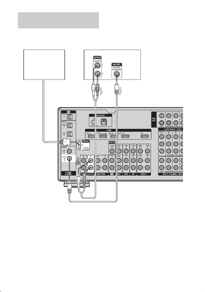
Connecting components with
digital audio output jacks
The following illustration shows how to
connect a Super Audio CD player, CD player
and DIGITAL MEDIA PORT adapter.
DIGITAL MEDIA PORT
adapter
Super Audio CD player, CD player
AB
A Audio cord (not supplied)
B Coaxial digital cord (not supplied)
GB
20
Page 21

Notes on connecting DIGITAL
MEDIA PORT adapter
• When connecting the DIGITAL MEDIA
PORT adapter, be sure the connector is
inserted with the arrow mark facing towards
the arrow mark on the DMPORT jack.
• Be sure to make DMPORT connections
firmly, insert the connector straight in.
• As the connector of the DIGITAL MEDIA
PORT adapter is fragile, be sure to handle
with care when placing or moving the
receiver.
• To disconnect the DIGITAL MEDIA PORT
adapter, squeeze the sides of the connector,
since the connector is locked in place.
Notes on playing a Super Audio
CD on a Super Audio CD player
• When you play a Super Audio CD, connect
the player to the MULTI CHANNEL INPUT
or SA-CD/CD IN jacks (analog input jack)
on this receiver. Refer to the operating
instructions supplied with the Super Audio
CD player.
• You cannot make digital recordings of a
Super Audio CD.
Getting Started
If you want to connect several
digital components, but cannot
find an unused input
See “Enjoying the sound/images from other
inputs” (page 88).
21
GB
Page 22
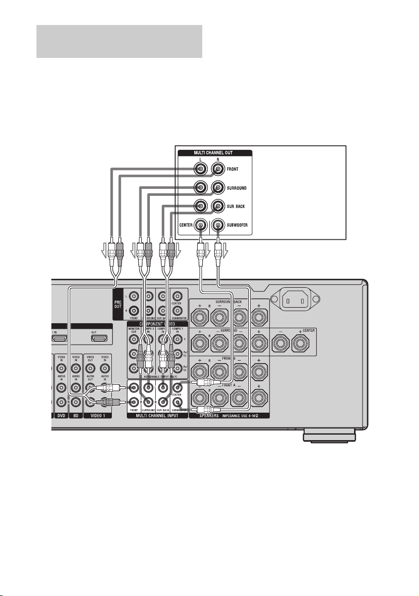
Connecting components with
multi channel output jacks
If your DVD or Super Audio CD player is
equipped with multi channel output jacks, you
can connect them to the MULTI CHANNEL
INPUT jacks of this receiver to enjoy multi
channel sound. Alternatively, the multi
channel input jacks can be used to connect an
external multi channel decoder.
DVD player,
Super Audio CD player,
etc.
A
A Audio cord (not supplied)
B Monaural audio cord (not supplied)
Note
Audio signals input from MULTI CHANNEL
INPUT jacks are not output to other audio output
jacks. The signals cannot be recorded.
B
22
GB
Page 23
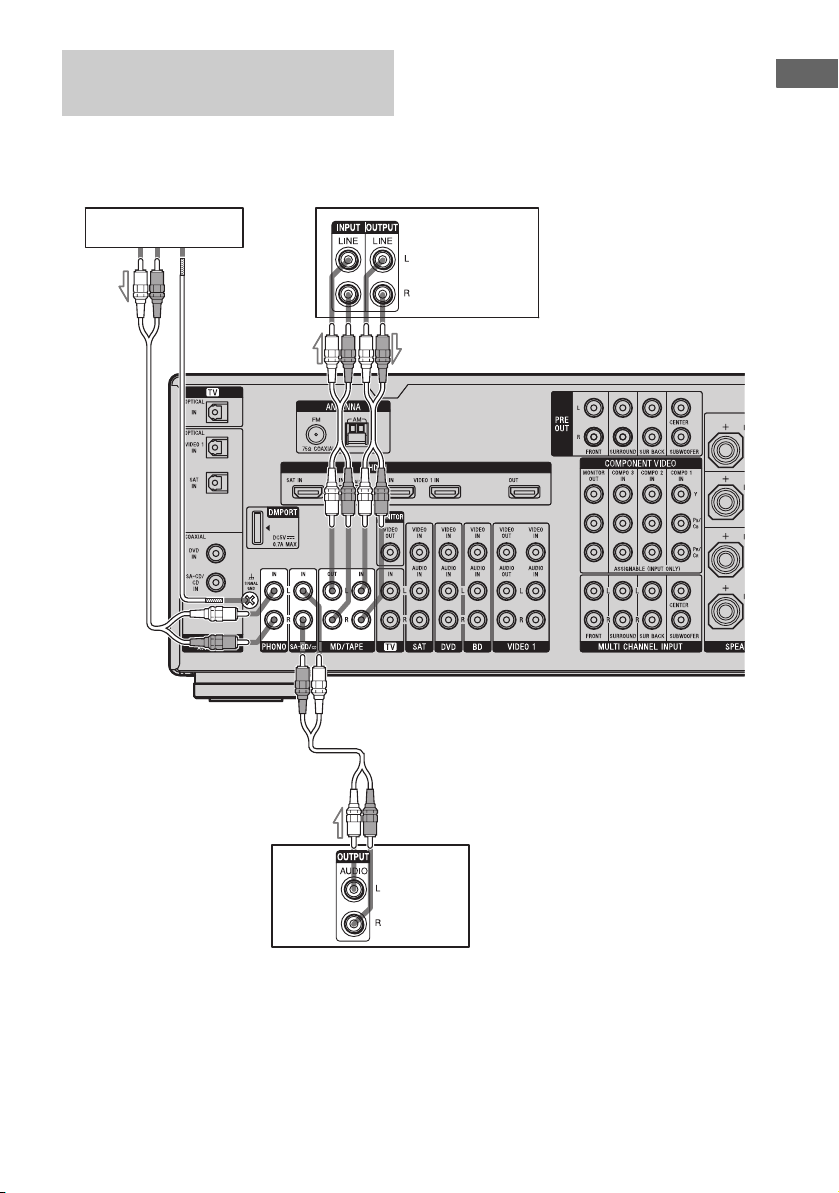
Connecting components with
analog audio jacks
The following illustration shows how to
connect a component with analog jacks, such
as tape deck, turntable, etc.
Getting Started
A
Tu r nt a b le
MD deck, Tape
deck
A
A
Super
Audio CD
player, CD
player
A Audio cord (not supplied)
Note
If your turntable has a ground (earth) wire, connect it to the U SIGNAL GND terminal.
23
GB
Page 24
4b: Connecting the video components
How to hook up your
components
This section describes how to hook up your
components to this receiver. Before you begin,
refer to “Component to be connected” below
for the pages which describe how to connect
each component.
After hooking up all your components,
proceed to “5: Connecting the antennas
(aerials)” (page 35).
Component to be connected Page
TV 18
With HDMI jack 25
Blu-ray disc player 28
DVD player 29
Satellite tuner, Set-top box 30
DVD recorder, VCR 31
Camcorder, video game, etc. 31
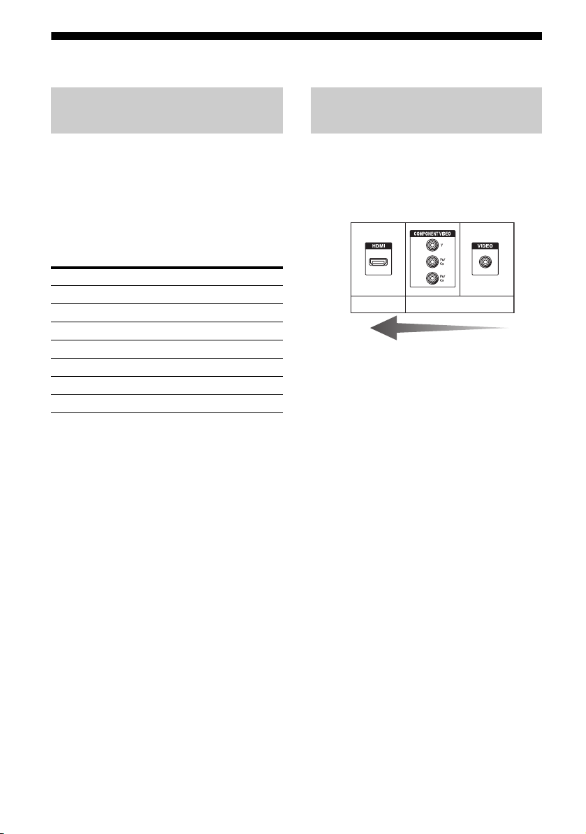
Video input/output jacks to be
connected
The image quality depends on the connecting
jack. Refer to the illustration that follows.
Select the connection according to the jacks on
your components.
Digital Analog
High quality image
Notes
• Before connecting cords, be sure to disconnect the
AC power cord.
• Be sure to turn on the receiver when the video and
audio signals of a playback component are being
output to a TV via the receiver. If the power supply
of the receiver is not turned on, neither video nor
audio is transmitted.
24
Converting video signals
This receiver is equipped with a function for upconverting video signals. For details, see page 32.
GB
Page 25

Connecting components with
HDMI jacks
HDMI is the abbreviated name for HighDefinition Multimedia Interface. It is an
interface which transmits video and audio
signals in digital format.
HDMI features
• A digital audio signals transmitted by HDMI
can be output from the speakers and the PRE
OUT jacks on this receiver. This signal
supports Dolby Digital, DTS and linear
PCM.
• This receiver can receive Multi Linear PCM
(up to 8 channels) with a sampling frequency
of 192 kHz or less with an HDMI
connection.
• Analog video signals input to the VIDEO
jack or COMPONENT VIDEO jacks can be
up-converted as HDMI signals. Audio
signals are not output from an HDMI OUT
jack when the image is converted.
• This receiver supports High Bitrate Audio
(DTS-HD Master Audio, Dolby TrueHD),
Deep Colour (Deep Color) and xvYCC
transmission, extended by HDMI ver1.3.
• This receiver supports the Control for HDMI
function. For details, see “Control for
HDMI” (page 77).
Getting Started
continued
25
GB
Page 26
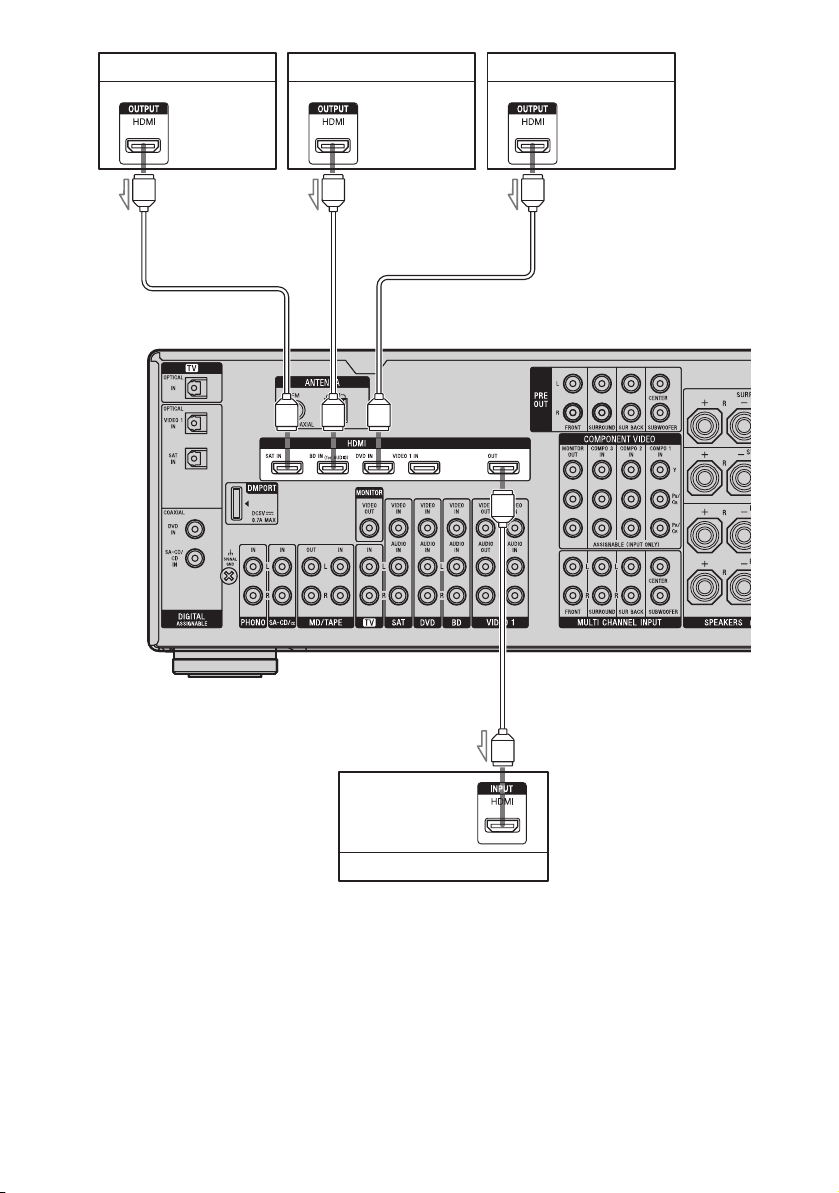
Audio/video
signals
Audio/video
signals
DVD playerSatellite tuner, Set-top box Blu-ray disc player
Audio/video
signals
A
AA
A
Audio/video
signals
A HDMI cable (not supplied)
We recommend that you use a Sony HDMI cable.
GB
26
TV, projector, etc.
Page 27

Notes on connecting cables
• We recommend that you use a Sony HDMI
cable.
• We recommend that you use an HDMI cable
with the HDMI logo (made by Sony) for the
HDMI jack corresponding to high speed (an
HDMI version1.3a, category 2 cable) when
you view images or listen to sound during a
Deep Colour (Deep Color) transmission or
when you watch a video image of 1080p or
higher.
• We do not recommend using an HDMI-DVI
conversion cable. When you connect an
HDMI-DVI conversion cable to a DVI-D
component, the sound and/or the image may
not be output. Connect other audio cords or
digital connecting cords, then set “Input
Assign” in the Input Option menu when the
sound is not output correctly.
Notes on HDMI connections
• Check the setup of the connected component
if an image is poor or the sound does not
come out of a component connected via the
HDMI cable.
• An audio signal input to the HDMI IN jack
is output from the speaker output jacks,
HDMI OUT jack and PRE OUT jacks. It is
not output from any other audio jacks.
• A video signal input to the HDMI IN jack
can only be output from the HDMI OUT
jack. The video input cannot be output from
the VIDEO OUT jacks or MONITOR
VIDEO OUT jacks.
• The audio and video signals of HDMI input
are not output from the HDMI OUT jack
while the receiver menu is displayed.
• When you want to listen to the sound from
the TV speaker, set “Audio Out” to
“TV+AMP” in the HDMI settings menu
(page 57). If you cannot play back multi
channel audio source, set to “AMP”.
However, the sound will not output from the
TV speaker.
• DSD signals of Super Audio CD are not
input and output.
• Be sure to turn on the receiver when the
video and audio of a playback component
are being output to a TV via the receiver. If
the power supply of the receiver is not turned
on, neither video nor audio is transmitted.
• Audio signals (sampling frequency, bit
length, etc.) transmitted from an HDMI jack
may be suppressed by the connected
component. Check the setup of the
connected component if an image is poor or
the sound does not come out of a component
connected via the HDMI cable.
• Sound may be interrupted when the
sampling frequency, the number of channels
or audio format of audio output signals from
the playback component is switched.
• When the connected component is not
compatible with copyright protection
technology (HDCP), the image and/or the
sound from the HDMI OUT jack may be
distorted or may not be output.
In this case, check the specification of the
connected component.
• You can enjoy High Bitrate Audio (DTS-HD
Master Audio, Dolby TrueHD), multi
channel Linear PCM only with an HDMI
connection.
• Set the image resolution of the playback
component to more than 720p to enjoy High
Bitrate Audio (DTS-HD Master Audio,
Dolby TrueHD).
• The image resolution of playback
component may need certain settings be
made before you can enjoy multi channel
Linear PCM. Refer to the operating
instructions of the player.
• Not every HDMI component supports all
functions that are defined by the specified
HDMI version. For example, components
that support HDMI, ver. 1.3a, may not
support Deep Colour (Deep Color).
• Refer to the operating instructions of each
component connected for details.
Getting Started
27
GB
Page 28
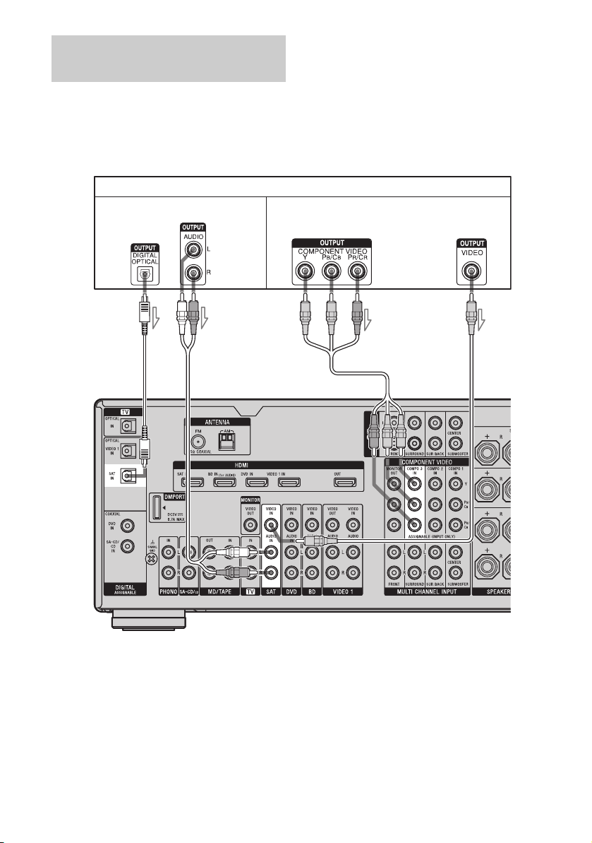
Connecting a Blu-ray Disc
Player
The following illustration shows how to
connect a Blu-ray Disc Player.
It is not necessary to connect all the cables.
Connect audio and video cords according to
the jacks of your components.
Blu-ray Disc Player
Audio signals Video signals
Note
To input multi channel digital audio from the Bluray Disc Player, set the digital audio output setting
on the Blu-ray Disc Player. Refer to the operating
instructions supplied with the Blu-ray Disc Player.
A Audio cord (not supplied)
B Component video cord (not supplied)
C Video cord (not supplied)
B
CA
Tip
The COMPONENT VIDEO COMPO 1 IN jacks
have been assigned to the Blu-ray Disc player. If you
connect your Blu-ray Disc player to the
COMPONENT VIDEO COMPO 2 or
COMPONENT VIDEO COMPO 3 IN jacks, set
“Input Assign” in the Input menu.
28
GB
Page 29
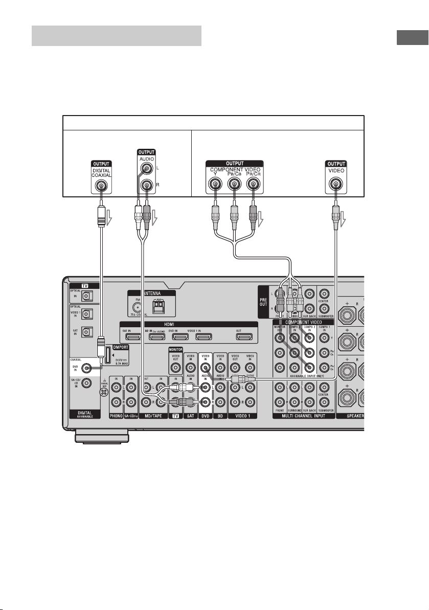
Connecting a DVD player
The following illustration shows how to
connect a DVD player.
It is not necessary to connect all the cables.
Connect audio and video cords according to
the jacks of your components.
Audio signals Video signals
Note
To input multi channel digital audio from the DVD
player, set the digital audio output setting on the
DVD player. Refer to the operating instructions
supplied with the DVD player.
DVD player
Getting Started
AB
A Coaxial digital cord (not supplied)
B Audio cord (not supplied)
C Component video cord (not supplied)
D Video cord (not supplied)
C
D
Tips
• All the digital audio jacks are compatible with
32 kHz, 44.1 kHz, 48 kHz, and 96 kHz sampling
frequencies.
• The COMPONENT VIDEO COMPO 2 IN jacks
have been assigned to the DVD player. If you
connect your DVD player to the COMPONENT
VIDEO COMPO 1 or COMPONENT VIDEO
COMPO 3 IN jacks, set “Input Assign” in the Input
menu.
29
GB
Page 30
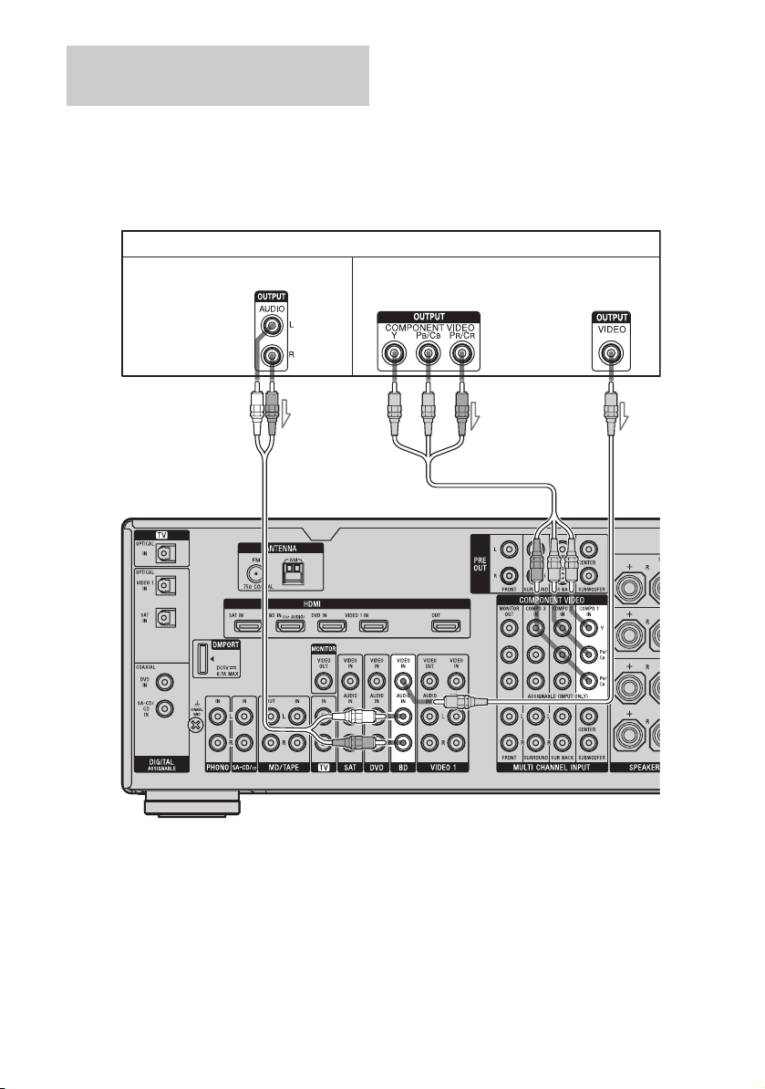
Connecting a satellite tuner,
Set-top box
The following illustration shows how to
connect a satellite tuner, Set-top box.
It is not necessary to connect all the cables.
Connect audio and video cords according to
the jacks of your components.
Satellite tuner, Set-top box
Audio signals Video signals
AB C D
Notes
• When connecting optical digital cords, insert the
plugs straight in until they click into place.
• Do not bend or tie optical digital cords.
A Optical digital cord (not supplied)
B Audio cord (not supplied)
C Component video cord (not supplied)
D Video cord (not supplied)
GB
30
Tips
• All the digital audio jacks are compatible with
32 kHz, 44.1 kHz, 48 kHz, and 96 kHz sampling
frequencies.
• The COMPONENT VIDEO COMPO 3 IN jacks
have been assigned to the satellite tuner. If you
connect your satellite tuner to the COMPONENT
VIDEO COMPO 1 or COMPONENT VIDEO
COMPO 2 IN jacks, set “Input Assign” in the Input
menu.
Page 31

Connecting components with
analog video and audio jack
The following illustration shows how to
connect a component which has analog jacks
such as a DVD recorder or VCR, etc.
It is not necessary to connect all the cables.
Connect audio and video cords according to
the jacks of your components.
Audio signals Video signals
Notes
• Be sure to change the factory setting of the VIDEO 1
input button on the remote so that you can use the
button to control your DVD recorder. For details, see
“Programming the remote” (page 107).
• You can also rename the VIDEO 1 input so that it
can be displayed on the TV screen and display
window. For details, see “Naming inputs”
(page 86).
DVD recorder, VCR
Getting Started
A
A Audio cord (not supplied)
B Video cord (not supplied)
C Audio/video cord (not supplied)
Camcorder,
video game
B
To the VIDEO 2 IN/PORTABLE
AV IN jacks (on the front panel)
C
31
GB
Page 32

Function for conversion of video
signals
For details on the video converting function,
see “In the video input/output conversion table
classified by the menu settings” (page 34).
This receiver is equipped with a function for
converting video signals. You can output the
video signal after connecting this receiver via
the MONITOR OUT or HDMI OUT jack as
shown in the illustration.
• Video signals can be output as HDMI video
and component video signals.
• Component video signals can be output as
HDMI video and video signals.
In the video input/output conversion table of the receiver
Refer to “In the video input/output conversion table classified by the menu settings” (page 34) on
the conversion function of images.
Output Signals
Input Signals
OUTPUT jack
INPUT jack
HDMI IN A f XX
COMPONENT
VIDEO IN B
VIDEO IN C aa f
a : Video signals are up-converted and output through the video converter.
f : The same type of signal as that of the input signal is output. Video signals are not converted.
X : Video signals are not output.
GB
32
HDMI OUT
aa/f X
COMPONENT VIDEO
MONITOR OUT
MONITOR VIDEO
OUT
Page 33

Notes on converting video signals
• When video signals from a VCR, etc., are
converted on this receiver and then output to
your TV, depending on the status of the
video signal output, the image on the TV
screen may appear distorted horizontally or
no image may be output.
• HDMI video signals cannot be converted to
component video signals and video signals.
• When you play a VCR with an image
improvement circuit, such as TBC, the
images may be distorted or may not be
output. In this case, set the image
improvement circuit function to off.
• The resolution of the signals output to the
COMPONENT VIDEO MONITOR OUT
jacks is converted up to 1080i. The
resolution of the signals output to the HDMI
OUT jack is converted up to 1080p.
• COMPONENT VIDEO MONITOR OUT
jacks have restrictions on resolution when
the resolution of video signals protected by
copyright technology is converted.
Resolution of up to 480p can be output to the
COMPONENT VIDEO MONITOR OUT
jacks. The HDMI OUT jack has no
restriction on resolution.
• Set “Resolution” to “AUTO” or “480/576i”
in the Video settings menu to output the
video signals from the MONITOR VIDEO
OUT and COMPONENT VIDEO
MONITOR OUT jack when both are
connected.
To display Closed Caption
Set “Resolution” to “DIRECT” in the Video
settings menu when receiving a signal that
supports Closed Captions.
Use the same kind of cords for the input/output
signals.
Getting Started
continued
33
GB
Page 34

In the video input/output conversion table classified by the menu
settings
For details on “Resolution” menu setting, see “Settings for the video (Video settings menu)”
(page 57) and on operating, see “Converting analog video input signals” (page 82).
“Resolution”
menu setting
Output from
Input signals
HDMI OUT jack COMPONENT
VIDEO MONITOR
OUT jacks
MONITOR VIDEO
OUT jack
DIRECT Component video X f X
Vid eo XXf
AUTO (initial setting) Component video a
Vid eo a
480/576i Component video a
Vid eo a
a)
a)
c)
c)
b)
a
b)
a
X
f
a X
af
480/576p Component video aaX
Vid eo aaf
720p, 1080i Component video aa
Vid eo aa
d)
d)
X
f
1080p Component video af X
Vid eo a X f
a : Video signals are up-converted and output through the video converter.
f : The same type of signal as that of the input signal is output. Video signals are not converted.
X : Video signals are not output.
a)
The resolution is set automatically, depending on the connected TV.
b)
When the TV is connected to jacks other than the HDMI jacks, 480/576i signals are output when “Resolution”
is set to “AUTO”.
c)
480/576p signals are output even if 480/576i is set.
d)
Video signals without copyright protection are output based on the settings menu. Video signals with
copyright protection are output as 480p.
Notes
• Video signals are not output from the COMPONENT VIDEO MONITOR OUT jacks when the monitor, etc.,
is connected to the HDMI OUT jack.
• If you select a resolution that the connected TV does not support in the “Resolution” menu, the images from
the TV cannot be output correctly.
• Converted HDMI image output signals do not support “x.v.Colour (x.v.Color)”.
• Converted HDMI image output signals do not support Deep Colour (Deep Color).
• When HDMI OUT jack is connected, there is no up-converted video signal output from COMPONENT
VIDEO MONITOR OUT jacks. The COMPONENT VIDEO MONITOR OUT jacks have component signal
direct output only.
34
GB
Page 35

5: Connecting the antennas (aerials)
Connect the supplied AM loop antenna
(aerial) and FM wire antenna (aerial).
Before connecting antennas, be sure to
disconnect the power cord.
AM loop antenna (aerial)
FM wire antenna (aerial) (supplied)
(supplied)
Getting Started
* The shape of the connector varies depending on
the area.
Notes
• To prevent noise pickup, keep the AM loop antenna
(aerial) away from the receiver and other
components.
• Be sure to fully extend the FM wire antenna
(aerial).
• After connecting the FM wire antenna (aerial),
keep it as horizontal as possible.
35
GB
Page 36

6: Preparing the receiver and the remote
Connecting the AC power cord
(mains lead)
Connect the supplied AC power cord (mains
lead) to the AC INLET terminal on the
receiver, then connect the AC power cord
(mains lead) to a wall outlet.
Notes
• Before connecting the AC power cord (mains
lead), make sure that metallic wires of the speaker
cords are not touching each other between the
SPEAKERS terminals.
• Connect the AC power cord (mains lead) firmly.
AC INLET terminal
Performing initial setup
operations
Before using the receiver for the first time,
initialize the receiver by performing the
following procedure. This procedure can also
be used to return settings you have made to
their factory defaults.
Be sure to use the buttons on the receiver for
this operation.
1,2 2,3
2,3
1 Press POWER to turn off the
receiver.
2 While holding down TONE
MODE and 2CH/A.DIRECT,
press POWER to turn on the
receiver.
To the wall outlet
AC power cord
(mains lead)
(supplied)
A several space is left between the plug and the
rear panel even when the power cord (mains
lead) is inserted firmly. The cord is supposed
to be connected this way. This is not
malfunction.
GB
36
3 Release TONE MODE and 2CH/
A.DIRECT after a few seconds.
After “CLEARING” appears on the
display for a while, “CLEARED !”
appears.
All the settings you have changed or
adjusted are reset to the initial settings.
Page 37

Inserting batteries into the
remote
Insert two R6 (size-AA) batteries in the RMAAP024 remote commander.
Insert two R6 (size-AA) batteries in the RMAAU039 remote control.
Observe the correct polarity when installing
batteries.
RM-AAP024 RM-AAU039
Notes
• Do not leave the remote in an extremely hot or
humid place.
• Do not use a new battery with old ones.
• Do not mix manganese batteries and other kinds of
batteries.
• Do not expose the remote sensor to direct sunlight
or lighting apparatuses. Doing so may cause a
malfunction.
• If you do not intend to use the remote for an
extended period of time, remove the batteries to
avoid possible damage from battery leakage and
corrosion.
• When you replace the batteries, the programmed
remote codes may be cleared. If this happens,
program the remote codes again (page 107).
Tip
When the remote no longer operates the receiver,
replace all the batteries with new ones.
About the command mode
The receiver and the remote use the same
command mode.
If the command modes of the receiver and the
remote are different, you cannot use the
remote to operate the receiver.
If the command modes of both the receiver and
the remote are those of the initial setting (AV
SYSTEM 2), it is not necessary to reset them.
You can switch the command mode (AV
SYSTEM 1 or AV SYSTEM 2) of the receiver
and the remote. If both the receiver and the
other Sony component respond to the same
remote command, switch the command mode
of either the component or the receiver to
another command mode so that the component
does not respond to the same remote command
as the receiver.
To switch the command mode
of the receiver
2CH/A.DIRECT
Turn on the receiver while pressing
2CH/A.DIRECT.
When the command mode is set to “AV2”,
“C. MODE AV2” appears on the display.
When the command mode is set to “AV1”,
“C. MODE AV1” appears on the display.
Getting Started
continued
37
GB
Page 38

To switch the command mode
of the RM-AAP024 remote
To switch the command mode
of the RM-AAU039 remote
11
THEATRE
SHIFT
123
VIDEO 1
456
DVD TV
789
MD/
TAPE
-/--
PHONO
CLEAR/>10
Press ?/1 while pressing RM SET UP.
1
The RM SET UP button flashes and the
SHIFT button indicator lights up.
2 Press 1 or 2 while the RM SET UP
button is flashing.
When you press 1, the command mode is
set to AV SYSTEM 1. When you press 2,
the command mode is set to AV SYSTEM
2.
3 Press ENT/MEM when the RM SET UP
button lights up.
The RM SET UP button flashes twice, then
the command mode setting process is
completed.
VIDEO 2
SAT
SA-CD/
CD
0/10
MULTI IN
AMPTV
BD
TUNER
ENT/MEM
DMPORT
2
DISPLAY
3
MUTING
Press and hold DISPLAY, then press
MUTING and at the same time.
SLEEP
DISPLAY
GUI MODE
38
GB
Page 39

7: Operating the receiver
using the GUI
Interface)
(Graphical User
1 Connect a TV to this receiver.
For details, see “3: Connecting the TV”
(page 18).
2 Turn on the TV.
Getting Started
You can change the display mode of the
receiver menu to the screen mode using the
following procedures. In the screen mode,
“GUI MODE” appears in the display window
of the receiver.
By using the GUI menu, you can make various
settings and adjustments.
For details, see “Operating without connecting
to the TV” (page 96) if you are not going to
use a GUI menu.
Note
GUI menu does not appear on the TV screen when
you have connected your TV to MONITOR VIDEO
OUT jack.
Displaying the GUI menu on the
TV screen
THEATRE
SHIFT
123
VIDEO 2
VIDEO 1
456
DVD TV
SAT
789
MD/
SA-CD/
TAPE
CD
-/--
0/10
MULTI IN
PHONO
CLEAR/>10
2CH/
A.F.D.
A.DIRECT
INPUT
MODERESOLUTION
AMPTV
BD
TUNER
ENT/MEM
DMPORT
MUSICMOVIE
NIGHT
MODESLEEP
GUI
MODE
3
4
3 Press ?/1 to turn on the
receiver.
4 Press GUI MODE repeatedly to
select “GUI ON”.
“GUI MODE” appears on the display
window of the receiver and the GUI menu
appears on the TV screen. Press MENU if
the GUI menu does not appear on the TV
screen.
5 Press V/v repeatedly to select a
menu you want, then press
or b.
HOME
5
MENU
39
GB
Page 40

Overview of the menus
The following menu items are available in
each settings menu.
Input
Selects the input to the receiver.
For details on each input, see “Selecting a
component” (page 50).
Music
You can enjoy sound and image from
component connected the DIGITAL MEDIA
PORT adapter.
For details on Music function, see “Selecting
an operation screen to operate the component
connected to the DIGITAL MEDIA PORT
adapter” (page 83).
FM/AM
You can listen to the radio using the receiver.
For details on Tuner operation, see “Tuner
Operations” (page 72).
Settings
You can use Settings menu to set and adjust
this receiver.
Auto Calibration
You can use the Auto Calibration settings
menu to adjust the speakers automatically.
For details, see “9: Calibrating the
appropriate speaker settings automatically
(Auto Calibration)” (page 44).
Surround
You can use the Surround settings menu to
select the sound field you want for your
listening pleasure. For details on adjusting
the parameters, see “Enjoying a preprogrammed sound field” (page 58).
EQ
You can use the EQ settings menu to adjust
the equalizer. For details, see “Adjusting the
equalizer” (page 71).
Audio
For details on adjusting the audio using the
Audio settings menu, see “Settings for the
audio (Audio settings menu)” (page 56).
Video
For details on adjusting the video using the
Video settings menu, see “Settings for the
video (Video settings menu)” (page 57).
HDMI
You can use the HDMI settings menu to
operate components connected to the HDMI
jacks. For details on adjusting the relevant
parameters, see “Settings for HDMI (HDMI
settings menu)” (page 57).
Speaker
You can use the Speaker settings menu to
adjust the speakers manually for the current
position, and to set the speaker impedance.
For details, see “Setting the speaker
impedances” (page 42) and “Adjusting the
speaker settings manually” (page 65).
GB
40
Page 41

Navigating through GUI menus
2CH/
A.DIRECT
A.F.D.
INPUT
MODERESOLUTION
MUSICMOVIE
NIGHT
MODESLEEP
GUI
MODE
1
2-9
3 Press or b to enter the
menu.
The menu item list appears on the TV
screen.
Getting Started
RETURN/
EXIT O
HOME
MENU
1 Press GUI MODE repeatedly to
select “GUI ON”.
“GUI MODE” appears on the display
window of the receiver and the GUI menu
appears on the TV screen. Press MENU if
the GUI menu does not appear on the TV
screen.
2 Press V/v repeatedly to select a
menu you want.
4 Press V/v repeatedly to select
the menu item you want to
adjust.
5 Press or b to enter the menu
item.
6 Press V/v repeatedly to select
the parameter you want to
adjust.
continued
41
GB
Page 42

7 Press or b to enter the
parameter.
8: Setting the speakers
Setting the speaker impedances
Set the appropriate speaker impedance for the
speakers you are using.
8 Press V/v repeatedly to select
the setting you want.
9 Press to enter the setting.
10Repeat steps 2 to 9 to make
other settings.
To return to the previous screen
Press RETURN/EXIT O.
To exit the menu
Press MENU.
To exit “GUI MODE”
Press GUI MODE repeatedly to select “GUI
OFF”.
2CH/
A.DIRECT
A.F.D.
INPUT
MODERESOLUTION
MUSICMOVIE
NIGHT
MODESLEEP
GUI
MODE
1
2-5
HOME
MENU
1 Press GUI MODE to select “GUI
ON”.
“GUI MODE” appears on the display
window of the receiver and the GUI menu
appears on the TV screen. Press MENU
if the GUI menu does not appear on the
TV screen.
2 Press V/v repeatedly to select
“Settings”, then press or b.
The Settings menu list appears on the TV
screen.
3 Press V/v repeatedly to select
“Speaker”, then press or b.
42
GB
Page 43

4 Press V/v repeatedly to select
“Speaker Impedance”, then
press or b.
5 Press V/v repeatedly to select
“4 ohms” or “8 ohms”
depending on the speakers you
are using, then press .
Notes
• If you are not sure of the impedances of the
speakers, refer to the operating instructions
supplied with your speakers. (This information is
often on the back of the speaker.)
• When you connect all speakers with a normal
impedance of 8 ohms or higher, set “Speaker
Impedance” to “8 ohms”. When connecting other
types of speakers, set it to “4 ohms”.
• When you connect front speakers to both the
SPEAKERS A and B terminals, connect the
speakers with a normal impedance of 8 ohms or
higher.
– When you connect speakers with impedance of
16 ohms or higher in both “A” and “B”
configuration:
Set “Speaker Impedance” to “8 ohms” in the
Speaker settings menu.
– For other types of speakers in other
configurations:
Set “Speaker Impedance” to “4 ohms” in the
Speaker settings menu.
Getting Started
43
GB
Page 44

Selecting the front speakers
You can select the front speakers you want to
drive.
Be sure to use the buttons on the receiver for
this operation.
SPEAKERS (OFF/A/B/A+B)
Press SPEAKERS (OFF/A/B/A+B)
repeatedly to select the front
speaker system you want to drive.
9: Calibrating the
appropriate speaker
settings automatically
(Auto Calibration)
The DCAC (Digital Cinema Auto Calibration)
function allows you to perform automatic
calibration, such as checking the connection
between each speaker and the receiver,
adjusting the speaker level, and measuring the
distance of each speaker from your seating
position automatically. Refer also to “Quick
Setup Guide” supplied with the receiver.
Before you perform the Auto
Calibration
To select Light up
The speakers connected to the
SPEAKERS FRONT A
terminals.
The speakers connected to the
SPEAKERS FRONT B
terminals.
The speakers connected to both
the SPEAKERS FRONT A and
B terminals (parallel
connection).
SP A
SP B
SP A + B
To turn off the speaker output
Press SPEAKERS (OFF/A/B/A+B)
repeatedly until the “SP A”, “SP B” and
“SP A + B” indicators on the display window
do not light up.
“ALL OFF” appears in the display window for
a while. No audio signals are output from any
speaker terminals.
Note
You cannot switch the front speaker system by
pressing SPEAKERS (OFF/A/B/A+B) when
the headphones are connected.
Before you perform the Auto Calibration, set
up and connect the speakers (page 14).
• The AUTO CAL MIC jack is used for the
supplied optimizer microphone only. Do not
connect other microphones. Doing so may
damage the receiver and the microphone.
• During the measurement, the sound that
comes out of the speakers is very loud. The
volume of the sound cannot be adjusted. Pay
attention to the presence of children or to the
effect on your neighborhood.
• Perform the measurement in a quiet
environment to avoid the effect of noise and
get a more accurate measurement.
• If there are any obstacles in the path between
the optimizer microphone and the speakers,
the calibration cannot be performed
correctly. Remove any obstacle from the
measurement area to avoid measurement
error.
• When you use a bi-amplifier connection, set
“BI-AMP Speaker” to “ON” in the Speaker
settings menu before you perform Auto
Calibration.
44
GB
Page 45

Notes
• The Auto Calibration function does not work if
– SPEAKERS (OFF/A/B/A+B) is set to off.
– headphones are connected.
• If the muting function has been activated before
you perform Auto Calibration, the muting function
will be set to off automatically.
Optimizer microphone
1 Connect the supplied optimizer
microphone to the AUTO CAL
MIC jack.
2 Set up the optimizer
microphone.
Place the optimizer microphone at your
seating position. Use a stool or tripod so
that the optimizer microphone remains at
the same height as your ears.
On setting up the active
subwoofer
• When a subwoofer is connected, turn on the
subwoofer and turn up the volume
beforehand. Turn the MASTER VOLUME
knob to just before the mid-point.
• If you connect a subwoofer with the
crossover frequency function, set the value
to maximum.
• If you connect a subwoofer with an auto
standby function, set subwoofer to off
(deactivated).
Note
Depending on the characteristics of the subwoofer
you are using, the setup distance value may be
further away from the actual position.
Using the receiver as a preamplifier
You can use the Auto Calibration function
when you use the receiver as a pre-amplifier.
In this case, the distance value shown on the
display may differ from the actual distance
value. However, there will be no problems
even if you continue to use the receiver with
that value.
Getting Started
45
GB
Page 46

Performing Auto Calibration
The Auto Calibration function allows you to
measure the following:
• Speaker connections
• Speaker polarity
• Speaker distance
• Speaker size
• Speaker level
• Frequency characteristics
a)
The measurement result is not utilized in the
following cases.
–The multi channel input is selected.
–“Analog Direct” is being used.
b)
The measurement result is not utilized in the
following cases.
–Dolby TrueHD signals with a sampling
frequency of more than 96 kHz are being
received.
–PCM signals with a sampling frequency of more
than 96 kHz are being received.
A.DIRECT
a)
a)
a)
a)b)
2CH/
A.F.D.
INPUT
MODERESOLUTION
MUSICMOVIE
NIGHT
MODESLEEP
MODE
GUI
1
2-5
HOME
MENU
3 Press V/v repeatedly to select
“Auto Calibration”, then press
or b.
4 Press V/v repeatedly to select
“Auto Calibration Start”, then
press or b.
5 Press to select “START”.
6 The measurement starts in five
seconds.
7 Measurement starts.
The measurement process will take
approximately 30 seconds with a test
tone. Wait until the measurement process
completes.
1 Press GUI MODE to select “GUI
ON”.
“GUI MODE” appears on the display
window of the receiver and the GUI menu
appears on the TV screen. Press MENU
if the GUI menu does not appear on the
TV screen.
2 Press V/v repeatedly to select
“Settings”, then press or b.
The Settings menu list appears on the TV
screen.
GB
46
Tip
The measurements may not be performed correctly
or Auto Calibration cannot be performed when
special speakers, such as dipole speakers are used.
Page 47

To cancel the measurement
The measurement will be canceled when you
do the following:
–Press ?/1, input buttons or MUTING.
– Press SPEAKERS (OFF/A/B/A+B) on the
receiver.
– Change the volume level.
– Connect the headphones.
Confirming/saving the
measurement results
1 Confirm the measurement
result.
When the measurement ends, a beep
sounds.
2 Press V/v to select the item you
want, then press .
Item Explanation
Retry Performs the Auto
Calibration again.
Save Saves the measurement
results and exits the setting
process.
Warning Displays warning
concerning the
measurement results. See
“Message list after Auto
Calibration measurement”
(page 49).
Phase* Displays the phase of each
speaker (in phase/out of
phase).
Distance Displays the measurement
result for speaker distance.
Level Displays the measurement
result for speaker level.
Exit Exits the setting process
without saving the
measurement results.
* When the speaker(s) is (are) out of the phase,
“OUT” is displayed on the TV screen. The
“+” and “–” terminals of the speaker may be
connected the other way around. However,
depending on the speakers, “OUT” appears
on the TV screen even though the speakers
are connected properly. This is because of the
speakers’ specifications. In this case, you can
continue to use the receiver.
Getting Started
3 Select “Save” in step 2, then
press to save the
measurement result.
continued
47
GB
Page 48

4 Press V/v repeatedly to select
the Auto Calibration Type, then
press .
Parameter Explanation
Full Flat Makes the measurement of
Engineer Sets the frequency to one
Front Reference Adjusts the characteristics
Off Sets the Auto Calibration
Tip
The size of a speaker (LARGE/SMALL) is
determined by the low characteristics. The
measurement results may vary, depending on the
position of the optimizer microphone and speakers,
and the shape of the room. It is recommended that
you follow the measurement results. However, you
can change those settings in the Speaker settings
menu. Save the measurement results first, then try to
change the settings if you want.
frequency from each
speaker flat.
that matches that of the
Sony listening room
standard.
of all the speakers to match
the characteristics of the
front speaker.
EQ to off.
48
GB
Page 49

Message list after Auto Calibration measurement
Error and
warning code
Error Code 31 SPEAKERS (OFF/A/B/A+B) is set to off. Set it to others and re-perform the measurement.
Error Code 32 None of the speakers were detected. Make sure that the optimizer microphone is connected
Error Code 33 • None of the front speakers are connected or only one front speaker is connected.
Warning 40 The measurement has completed. However, the noise level is high. You may be able to
Warning 41 The input from the microphone is too big.
Warning 42 The input from the microphone is too big.
Warning 43 The distance and position of a subwoofer cannot be detected. This may be caused by noise.
NO WARNING There is no warning information.
Explanation
properly and reperform the measurement.
If the optimizer microphone is connected properly but the error code appears, the optimizer
microphone cable may be damaged or improperly connected.
• The optimizer microphone is not connected.
• Either the left or right surround speakers is not connected.
• Surround back speakers are connected even though surround speakers are not connected.
Connect the surround speaker(s) to the SURROUND terminals.
• The surround back speaker is connected only to the SPEAKERS SURROUND BACK R
terminals. When you connect only one surround back speaker, connect it to the SPEAKERS
SURROUND BACK L terminals.
perform the measurement properly if you try it again, even though the measurement cannot
be performed in all environments. Try to perform the measurement in a quiet environment.
• It may be too close the distance between the speaker and the microphone. Retry the
m ea su r em en t a f te r s e tt in g ap ar t f r om ea c h o th er .
• It may be that the volume is too big when you use the receiver as a preamp.
• It may be too close the distance between the speaker and the microphone. Retry the
m ea su r em en t a f te r s e tt in g ap ar t f r om ea c h o th er .
• It may be that the volume is too big when you use the receiver as a preamp.
Try to perform the measurement in a quiet environment.
Getting Started
•Error Code 31, 32, 33
When you press , “RETRY?” appears.
1
2 Press B/b to select “YES”.
3 Press , then follow the instructions from
step 1 of “Performing Auto Calibration”.
When a warning code appears
If a warning on the measurement result is
present, detailed information is displayed.
Press to return to step 1 of
“Confirming/saving the measurement
results” (page 47).
Tip
Depending on the position of the subwoofer, the
measurement results for polarity may vary.
However, there will be no problems even if you
continue to use the receiver with that value.
To set Auto Calibration items
more precisely
On the Auto Calibration setting menu,
press .
• Auto Calibration Type
You can select this parameter only when you
have performed the Auto Calibration and
saved the measurement result.
For details, see the table on page 48.
• Position
You can register three patterns as Position 1,
2, and 3, depending on the seating position,
listening environment, and measurement
conditions.
• Name Input
You can rename the position number. For
details, refer to “Naming inputs” (page 86).
49
GB
Page 50

Playback
Selecting a component
THEATRE
THEATRE
SHIFT
SHIFT
123
123
VIDEO 1
VIDEO 1
456
456
DVD TV
DVD TV
789
789
MD/
MD/
TAPE
TAPE
-/--
-/--
PHONO
PHONO
CLEAR/>10
CLEAR/>10
2CH/
2CH/
A.F.D.
A.DIRECT
A.F.D.
A.DIRECT
TUNING
TUNING
DISC SKIP
3
DISC SKIP
INPUT
INPUT
MODERESOLUTION
MODERESOLUTION
VIDEO 2
VIDEO 2
SAT
SAT
SA-CD/
SA-CD/
CD
CD
0/10
0/10
MULTI IN
MULTI IN
HOME
HOME
AMPTV
AMPTV
BD
BD
TUNER
TUNER
ENT/MEM
ENT/MEM
DMPORT
DMPORT
MUSICMOVIE
MUSICMOVIE
NIGHT
NIGHT
MODESLEEP
MODESLEEP
GUI
GUI
MODE
MODE
TUNING
TUNING
D.TUNING
D.TUNING
Selected
input
Components that can be
played back
VIDEO 1 VCR, etc., connected to the
VIDEO 1 jack.
VIDEO 2 Video camera and TV game,
etc., connected to the VIDEO
2 IN/PORTABLE AV IN jack.
BD Blu-ray disc player, etc.,
connected to the BD jack.
DVD DVD player, etc., connected
to the DVD jack.
1
SAT Satellite tuner, etc., connected
to the SAT jack.
TV TV connected to the TV jack.
MD/TAPE MD or Tape deck, etc.,
connected to the MD/TAPE
jack.
SA-CD/CD Super Audio CD or CD
player, etc., connected to the
SA-CD/CD jack.
TUNER Built-in radio tuner.
PHONO Turntable, etc., connected to
the PHONO jack.
MULTI IN Component connected to the
MULTI CHANNEL INPUT
jack.
DMPORT Portable audio, etc.,
connected to the DIGITAL
MEDIA PORT adapter
connected to the receiver.
MUTING
BD/DVD
BD/DVD
TOP MENU
MENU
TOP MENU
MENU
F1 F2
TV INPUT WIDE
TV INPUT WIDE
1
Press one of the input buttons
F1 F2
to select the component you
want.
You can also use INPUT SELECTOR on
the receiver or the RM-AAU039 remote.
The selected input appears on the display.
GB
50
2 Turn on the component and
start playback.
3 Press MASTER VOL +/– to
adjust the volume.
You can also use MASTER VOLUME on
the receiver.
Page 51

Tips
• You can adjust the volume differently depending
on the speed with which you turn the MASTER
VOLUME on the receiver.
To turn the volume up or down quickly: turn the
knob quickly.
To make fine adjustment: turn the knob slowly.
• You can adjust the volume differently depending
on the length of time you press and hold the
MASTER VOL +/– button on the remote.
To turn the volume up or down quickly: press and
hold the button.
To make a fine adjustment: press the button and
release it immediately.
To activate the muting function
Press MUTING.
The muting function will be canceled when
you do the following.
• Press MUTING again.
• Increase the volume.
• Turn off the receiver.
To avoid damaging your
speakers
Before you turn off the receiver, be sure to turn
down the volume level.
Playback
51
GB
Page 52

Listening to a Super Audio CD/CD
SLEEP
DISPLAY
GUI MODE
2
3
5
• The operation is described for a
Sony Super Audio CD player.
• Refer to the operating
instructions supplied with the
Super Audio CD player or CD
player.
z
You can select the sound field to
suit the music. Refer to page 63
for details.
5
3
1 Turn on the Super Audio CD player or CD
player, then place the disc in the tray.
2 Turn on the receiver.
3 Press INPUT SELECTOR to select “SA-CD/
CD”.
You can also use INPUT SELECTOR on this receiver to
select “SA-CD/CD”.
4 Play back the disc.
5 Adjust to a suitable volume.
52
6 After you have finished listening to a Super
Audio CD or CD, eject the disc and turn off
the receiver and the Super Audio CD player
or CD player.
GB
Page 53

Watching a DVD/Blu-ray Disc
SLEEP
DISPLAY
2
GUI MODE
3
6
• Refer to the operating
instructions supplied with the
TV and DVD player or Blu-ray
Disc Player.
z
Select the audio format of the disc
to be played, if necessary.
z
You can select the sound field to
suit the movie or the music. Refer
to page 63 for details.
Check the following if you cannot
listen to the multi channel sound.
• Be sure the sound source
corresponds to the multi channel
format (the MULTI CHANNEL
DECODING lamp on the front
panel lights up during
playback).
• Be sure this receiver is
connected to the DVD player or
Blu-ray Disc Player via a digital
connection.
• Be sure the digital audio output
of the DVD player or Blu-ray
Disc Player is set up properly.
Playback
6
3
MULTI CHANNEL DECODING lamp
1 Turn on the TV and DVD player or Blu-ray
Disc Player.
2 Turn on the receiver.
3 Press INPUT SELECTOR to select “DVD” or
“BD”.
You can also use INPUT SELECTOR on this receiver to
select “DVD” or “BD”.
4 Switch the input of the TV so that an image
of the DVD or Blu-ray Disc is displayed.
5 Play back the disc.
6 Adjust to a suitable volume.
7 After you have finished watching a DVD or
Blu-ray Disc, eject the disc and turn off the
receiver, the TV, and the DVD player or Bluray Disc Player.
53
GB
Page 54

Enjoying video games
SLEEP
DISPLAY
GUI MODE
2
3
6
• Refer to the operating
instructions supplied with the
TV and video game.
6
3
VIDEO 2 IN/PORTABLE AV IN
1 Turn on the TV and video game.
2 Turn on the receiver.
3 Press INPUT SELECTOR to select “VIDEO
2”*.
You can also use INPUT SELECTOR on this receiver to
select “VIDEO 2”*.
* When you connect a video game to the VIDEO 2 IN/
PORTABLE AV IN jack on the front panel.
4 Switch the input of the TV so that an image
of the video game is displayed.
54
5 Place the disc in the tray and play it back on
the video game.
6 Adjust to a suitable volume.
7 After you have finished playing a game, eject
the disc and turn off the receiver, the TV and
the video game.
GB
Page 55

Watching video
SLEEP
DISPLAY
GUI MODE
2
3
6
• Refer to the operating
instructions supplied with the
TV and VCR.
Playback
6
3
1 Turn on the VCR.
2 Turn on the receiver.
3 Press INPUT SELECTOR to select “VIDEO
1”*.
You can also use INPUT SELECTOR on this receiver to
select “VIDEO 1”*.
* When you connect VCR to the VIDEO 1 jack.
4 Switch the input of the TV so that an image
of the VCR is displayed.
5 Play back the tape on the VCR.
6 Adjust to a suitable volume.
7 After you have finished watching a video,
eject the tape and turn off the receiver, the
TV and the VCR.
55
GB
Page 56

Amplifier Operations
Settings for the audio
(Audio settings menu)
You can use the Audio settings menu to make
settings for the audio to suit your preference.
Select “Audio” in the Settings menu. For
details on adjusting the parameters, see “7:
Operating the receiver using the GUI
(Graphical User Interface)” (page 39).
Audio settings menu parameters
x A/V Sync
(Synchronizes audio and video
output)
Lets you delay the output of audio to minimize
the time gap between audio output and visual
display. You can adjust the delay from 0 ms to
300 ms in 10 ms steps.
Notes
• This parameter is useful when you use a large LCD
or plasma monitor or a projector.
• This parameter is not valid when
– the multi channel input is selected.
– “Analog Direct” is being used.
x Decode Priority
(Digital audio input decoding
priority)
Lets you specify the input mode for the digital
signal input to the HDMI IN jacks.
•PCM
When signals from the HDMI IN jack are
selected, only PCM signals are output from
the connected player. To prevent interruption
when playback starts, set to “PCM”. When
signals in any other format are received, set
this item to “AUTO”.
•AUTO
Automatically switches the input mode
between Dolby Digital, DTS or PCM.
Note
Even when “Decode Priority” is set to “PCM”, the
sound may be interrupted at the very beginning of
the first track depending on the CD being played
back.
x Dual Mono
(Digital broadcast language
selection)
Lets you select the language you want to listen
to during a digital broadcast. This feature only
functions for Dolby Digital sources.
• Main/Sub
Sound of the main language will be output
through the front left speaker, and sound of
the sub language will be output through the
front right speaker simultaneously.
•Main
Sound of the main language will be output.
•Sub
Sound of the sub language will be output.
GB
56
Page 57

Settings for the video
Settings for HDMI
(Video settings menu)
You can use the Video settings menu to make
settings for video. Select “Video” in the
Settings menu. For details on adjusting the
parameters, see “7: Operating the receiver
using the GUI (Graphical User Interface)”
(page 39).
(HDMI settings menu)
You can use the HDMI menu to make the
required settings for components connected to
the HDMI jack. Select “HDMI” in the Settings
menu. For details on adjusting the parameters,
see “7: Operating the receiver using the GUI
(Graphical User Interface)” (page 39).
Video settings menu parameters HDMI settings menu parameters
x Resolution
(Converting Video signals)
Lets you convert the resolution of analog video
input signals.
•DIRECT
•AUTO
• 480/576i
• 480/576p
• 720p
• 1080i
• 1080p
For details on operating, see “In the video
input/output conversion table classified by the
menu settings” (page 34).
x Control for HDMI
Lets you turn the Control for HDMI function
on or off. For details, see “Control for HDMI”
(page 77).
x Audio Out
(Setting HDMI audio input)
Lets you set the HDMI audio signals output
from the playback component connected to the
receiver via an HDMI connection.
• TV+AMP
The sound is output from TV’s speaker and
the speakers connected to the receiver.
Notes
• The sound quality of the playback component
depends on the TV’s sound quality, such as the
number of channels, and the sampling
frequency, etc. When the TV has stereo
speakers, the sound output from the receiver is
also stereo as that of the TV, even if you play
back multi channel source.
• When you connect the receiver to an image
display component (projector, etc.), sound may
not be output from the receiver. In this case,
select “AMP”.
•AMP
The HDMI audio signals from the playback
component is only output to speakers
connected to the receiver. The multi channel
sound can be played back as it is.
Note
Audio signals are not output from the TV speakers
when “Audio Out” is set to “AMP”.
Amplifier Operations
continued
57
GB
Page 58

x SW Level (Subwoofer level for
MODE
GUI
HOME
MODE
GUI
HOME
HDMI)
Lets you set the level of the subwoofer to 0 dB
or +10 dB when PCM signals are input via an
HDMI connection. You can set the level for
each HDMI input independently.
•AUTO
The subwoofer level is automatically set to 0
dB or +10 dB depending on the sampling
frequency.
•+10 dB
•0 dB
Enjoying Surround Sound
Enjoying a preprogrammed sound field
2
3-6
MENU
Start playing a sound source
1
you want to listen to (CD, DVD,
etc.).
2 Press GUI MODE to select “GUI
ON”.
“GUI MODE” appears on the display
window of the receiver and the GUI menu
appears on the TV screen. Press MENU
if the GUI menu does not appear on the
TV screen.
58
GB
3 Press V/v repeatedly to select
“Settings”, then press or b.
The Settings menu list appears on the TV
screen.
4 Press V/v repeatedly to select
“Surround”, then press or
b.
5 Press V/v repeatedly to select
“Sound Field Setup”, then
press or b.
Page 59

6 Press V/v repeatedly to select
the surround sound you want.
To select enhanced surround
mode
1 Select “Enhanced Sur Mode” in step 5
above.
2 Press V/v repeatedly to select the enhanced
surround sound you want.
3 Press .
Note
The selected enhanced surround mode can only be
applied if you have selected “Enhanced Sur” as a
sound field in “Sound Field Setup” parameter.
To adjust the effect level
1 After you have selected the surround sound
in step 6, press
2 Press V/v repeatedly to adjust the effect
level, then press /B/b.
Higher settings apply more surround effect.
You can adjust the effect level in 4 steps
(50%, 80%, 100%, 150%).
or b.
Types of 2CH mode
x 2ch Stereo
The receiver outputs the sound from the front
left/right speakers only. There is no sound
from the subwoofer.
Standard 2 channel stereo sources completely
bypass the sound field processing and multi
channel surround formats are downmixed to 2
channel except LFE signals.
Note
No sound is output from the subwoofer in the 2ch
Stereo mode. To listen to 2 channel stereo sources
using the front left/right speakers and a subwoofer,
select “A.F.D. Auto”.
This receiver will generate a low frequency signal
for output to the subwoofer when there is no LFE
signal, which is a low-pass sound effect output from
a subwoofer to a 2 channel signal.
x Analog Direct
You can switch the audio of the selected input
to 2 channel analog input. This function
enables you to enjoy high quality analog
sources.
When using this function, only the volume and
front speaker balance can be adjusted.
Enjoying Surround Sound
Note
You may not able to adjust the effect level for some
sound field.
59
GB
Page 60

When connecting Blu-ray disc players and other next generation HD
players
This receiver supports the following audio formats.
Audio format
Maximum number
of channels
Dolby Digital 5.1ch aa
Dolby Digital EX 6.1ch aa
Dolby Digital Plus
Dolby TrueHD
a)
a)
7.1ch
7.1ch × a
DTS 5.1ch aa
DTS-ES 6.1ch aa
DTS 96/24 5.1ch aa
DTS-HD
High Resolution Audio
DTS-HD
Master Audio
a) b)
a)
Multi channel Linear PCM
a)
Audio signals are output in another format if the playback component does not correspond to the format. For
details, refer to the operating instructions of the playback component.
b)
Signals with a sampling frequency of more than 96 kHz are played back at 96 kHz.
7.1ch
7.1ch
a)
7.1ch × a
Connection of the playback component and
the receiver
COAXIAL/OPTICAL HDMI
× a
× a
× a
60
GB
Page 61

Types of A.F.D. mode
The Auto Format Direct (A.F.D.) mode allows
you to listen to higher fidelity sound and select
the decoding mode for listening to a 2 channel
stereo sound as multi channel sound.
A.F.D. mode
[appears on TV screen]
A.F.D. Auto
[A.F.D. Auto]
Enhanced Surround Mode
[Enhanced Sur]
Pro Logic II*
[PL II]
Pro Logic IIx*
[PL IIx]
Neo:6 Cinema
[Neo:6 Cinema]
Neo:6 Music
[Neo:6 Music]
Neural-THX
[Neural-THX]
Multi Stereo
[Multi Stereo]
* Depends on the speaker pattern setting, some enhanced surround mode parameter may not be available.
®
Notes
• This function does not work in the following cases.
– The multi channel input is selected.
– DTS-HD signals with a sampling frequency of
more than 48 kHz are being received.
– Dolby TrueHD signals with a sampling
frequency of more than 48 kHz are being
received.
– “Analog Direct” is being used.
• The beginning of the sound stream may be dropped
out when Neural-THX
off.
®
processing is turned on or
Multi channel
audio after
decoding
(Detecting
automatically)
5-channel signals Performs Dolby Pro Logic II decoding.
7-channel signals Performs Dolby Pro Logic IIx decoding.
7-channel signals Performs DTS Neo:6 Cinema mode decoding.
7-channel signals Performs DTS Neo:6 Music mode decoding. This
7-channel signals Next generation of Neural-THX
(Multi Stereo) Outputs 2 channel left/right signals from all speakers.
Effect
Presets the sound as it was recorded/encoded without
adding any surround effects.
setting is ideal for normal stereo sources such as CDs.
®
addition to stereo enhancement processing and pure
discrete 5.1 surround sound, now capable of full 360°
7.1 surround sound playback from Neural-THX
Surround encoded content.
However, sound may not be output from certain
speakers depending on the speaker settings.
Surround. In
Tips
• You can identify the encoding format of DVD
software, etc., by looking at the logo on the
package.
• Dolby Pro Logic IIx decoding is effective, when a
multi channel signal is input.
Enjoying Surround Sound
®
continued
61
GB
Page 62

If you connect a subwoofer
This receiver will generate a low frequency
signal for output to the subwoofer when there
is no LFE signal, which is a low-pass sound
effect output to a subwoofer from a 2 channel
signal. However, the low frequency signal is
not generated for “Neo:6 Cinema” or “Neo:6
Music” when all speakers are set to “LARGE”.
In order to take full advantage of the Dolby
Digital bass redirection circuitry, we
recommend setting the subwoofer’s cut off
frequency as high as possible.
62
GB
Page 63

Types of music/movie mode
You can take advantage of surround sound
simply by selecting one of the receiver’s
preprogrammed sound fields. They bring the
exciting and powerful sound of movie theaters
and concert halls into your home.
Sound field
for
Movie Cinema Studio EX A
Music Hall [Hall] Reproduces the acoustics of a classical concert hall.
Headphone
a)
You can select this sound field mode if the headphones are connected to the receiver.
b)
Appears on the display window only.
Sound field
[appears on TV screen]
DCS
[Cinema St EX A]
Cinema Studio EX B
DCS
[Cinema St EX B]
Cinema Studio EX C
DCS
[Cinema St EX C]
V.Multi Dimension
DCS [V.Multi Dimension]
Jazz Club [Jazz Club] Reproduces the acoustics of a jazz club.
Live Concert [Live Concert] Reproduces the acoustics of a 300-seat live house.
Stadium [Stadium] Reproduces the feeling of a large open-air stadium.
Sports [Sports] Reproduces the feeling of sports broadcasting.
Portable Audio Enhancer
[Portable Audio]
a)
Headphone (2ch)
[HP (2CH)]
Headphone Theater DCS
[HP Theater]
Headphone (Multi)
[HP MULTI]
Headphone (Direct)
[HP (Direct)]
b)
Effect
Reproduces the sound characteristics of the Sony Pictures
Entertainment “Cary Grant Theater” cinema production
studio. This is a standard mode, great for watching almost any
type of movie.
Reproduces the sound characteristics of the Sony Pictures
Entertainment “Kim Novak Theater” cinema production
studio. This mode is ideal for watching science-fiction or
action movies with lots of sound effects.
Reproduces the sound characteristics of the Sony Pictures
Entertainment scoring stage. This mode is ideal for watching
musicals or films where orchestra music is featured in the
soundtrack.
Creates many virtual speakers from a single pair of actual
surround speakers.
Reproduces a clear enhanced sound image from your portable
audio device. This mode is ideal for MP3 and other
compressed music.
This mode is selected automatically if you use headphones
when “2ch Stereo” mode or A.F.D. mode is selected. Standard
2 channel stereo sources completely bypass the sound field
processing and multi channel surround formats are
downmixed to 2 channels except LFE signals.
This mode is selected automatically when you use headphones
when sound field is selected for movie/music. It allows you to
experience a theater-like environment while listening through
a pair of headphones.
This mode is selected automatically if you use headphones
when the multi channel input is selected. Outputs the front
analog signals from the MULTI CHANNEL INPUT jacks.
Outputs the analog signals without processing by the tone,
sound field, etc.
continued
63
Enjoying Surround Sound
GB
Page 64

Notes
• The sound fields for music and movies do not work
in the following cases.
– The multi channel input is selected.
– DTS-HD signals with a sampling frequency of
more than 48 kHz are being received.
– Dolby TrueHD signals with a sampling
frequency of more than 48 kHz are being
received.
– Signals with a sampling frequency of more than
48 kHz are being received.
– The multi channel PCM signals are received via
a HDMI IN jack.
• When one of the sound fields for music is selected,
no sound is output from the subwoofer if all the
speakers are set to “LARGE” in the Speaker
settings menu.
However, the sound will be output from the
subwoofer if
– the digital input signal contains LFE signals.
– the front and surround speakers are set to
“SMALL”.
– the sound field for movie is selected.
– “Portable Audio” is selected.
Tips
• You can identify the encoding format of DVD
software, etc., by looking at the logo on the
package.
• Sound fields with DCS marks use DCS
technology. See “Glossary” (page 112).
• When the sound field’s DCS mark is selected,
the Digital Cinema Sound lamp lights up on the
display.
Resetting sound fields to the initial settings
Be sure to use the buttons on the receiver for
this operation.
1,2
2
1 Press POWER to turn off the
receiver.
2 While holding down MUSIC,
press POWER.
“S.F. CLEAR” appears on the display and
all sound fields are reset to their initial
setting.
To turn off the surround effect
for MOVIE/MUSIC
Select “2ch Stereo” or “A.F.D. Auto” in the
Surround settings menu.
GB
64
Page 65

Enjoying the surround
effect at low volume
levels
(NIGHT MODE)
This function allows you to retain a theater like
environment at low volume levels. This
function can be used with other sound fields.
When watching a movie late at night, you will
be able to hear the dialog clearly even at a low
volume level.
2CH/
2CH/
A.F.D.
A.DIRECT
A.F.D.
A.DIRECT
INPUT
INPUT
MODERESOLUTION
MODERESOLUTION
Press NIGHT MODE.
The NIGHT MODE function is activated. The
NIGHT MODE is set to on and off as you
press NIGHT MODE.
Note
This function does not work in the following cases.
– The multi channel input is selected.
– Dolby TrueHD signals with a sampling frequency
of more than 96 kHz are being received.
– PCM signals with a sampling frequency of more
than 96 kHz are being received.
MUSICMOVIE
MUSICMOVIE
NIGHT
NIGHT
MODESLEEP
MODESLEEP
MODE
MODE
NIGHT
GUI
GUI
MODE
Advanced Speakers Setting Up
Adjusting the speaker settings manually
You can adjust each speaker manually.
You can also adjust the speaker levels after the
Auto Calibration is completed.
Making settings with the
Manual Setup menu
2CH/
2CH/
A.DIRECT
A.DIRECT
A.F.D.
A.F.D.
INPUT
INPUT
MODERESOLUTION
MODERESOLUTION
MUSICMOVIE
MUSICMOVIE
NIGHT
NIGHT
MODESLEEP
MODESLEEP
MODE
MODE
GUI
GUI
1
2-8
HOME
HOME
MENU
1 Press GUI MODE repeatedly to
select “GUI ON”.
“GUI MODE” appears on the display
window of the receiver and the GUI menu
appears on the TV screen. Press MENU
if the GUI menu does not appear on the
TV screen.
2 Press V/v repeatedly to select
“Settings”, then press or b.
The Settings menu list appears on the TV
screen.
Advanced Speakers Setting Up
3 Press V/v repeatedly to select
“Speaker”, then press or b.
continued
65
GB
Page 66

4 Press V/v repeatedly to select
“Manual Setup”, then press
or b.
5 Press V/v/B/b to select speaker
you want to adjust.
6 Press .
7 Press B/b repeatedly to select
the parameter you want.
8 Press V/v repeatedly to adjust
the setting.
Manual Setup menu parameters
x Level
(Level of speaker)
You can adjust each speaker’s level (center,
surround left/right, surround back left/right,
subwoofer). You can adjust the level from –20
dB to +10 dB in 0.5 dB steps.
For the front left/right speakers, you can adjust
the balance on either side. You can adjust the
front left level from –10.0 dB to +10.0 dB in
0.5 dB steps. You can also adjust the front right
level from –10.0 dB to +10.0 dB in 0.5 dB
steps.
x Distance
(Distance from the seating
position to each speaker)
You can adjust the distance from the listening
position to each speaker (front left/right,
center, surround left/right, surround back left/
right, subwoofer).
You can adjust the distance from 1.0 meter to
10.0 meters (3 feet 3 inches to 32 feet
9 inches) in 0.01 meter (1 inch) steps.
66
GB
Page 67

x Size
(Size of each speaker)
You can adjust each speaker’s (front left/right,
center, surround left/right, surround back left/
right) size.
• LARGE
If you connect large speakers that will
effectively reproduce bass frequencies,
select “LARGE”. Normally, select
“LARGE”.
•SMALL
If the sound is distorted, or you feel a lack of
surround effects when using multi channel
surround sound, select “SMALL” to activate
the bass redirection circuitry and output the
bass frequencies of each channel from the
subwoofer or other “LARGE” speakers.
Note
When one of the sound fields for music is selected,
no sound is output from the subwoofer if all the
speakers are set to “LARGE”. However, the sound
will be output from the subwoofer if the digital input
signal contains LFE signals, or if the front or
surround speakers are set to “SMALL”, the sound
field for movie is selected, or “Portable Audio” is
selected.
Tips
• The “LARGE” and “SMALL” settings for each
speaker determine whether the internal sound
processor will cut the bass signal from that
channel.
When the bass is cut from a channel, the bass
redirection circuitry sends the corresponding bass
frequencies to the subwoofer or other “LARGE”
speakers.
However, since bass sound has a certain amount of
directionality, it is best not to cut it, if possible.
Therefore, even when using small speakers, you
can set them to “LARGE” if you want to output the
bass frequencies from that speaker. On the other
hand, if you are using a large speaker, but prefer not
to have bass frequencies output from that speaker,
set it to “SMALL”.
If the overall sound level is lower than you prefer,
set all speakers to “LARGE”. If there is not enough
bass, you can use the equalizer to boost the bass
levels.
• The surround back speakers will be set to the same
setting as that of the surround speakers.
• When the front speakers are set to “SMALL”, the
center, surround, and surround back speakers are
also automatically set to “SMALL”.
• If you do not use the subwoofer, the front speakers
are automatically set to “LARGE”.
Advanced Speakers Setting Up
67
GB
Page 68

Making settings with the
Speaker Pattern menu
2CH/
2CH/
A.DIRECT
A.DIRECT
A.F.D.
A.F.D.
INPUT
INPUT
MODERESOLUTION
MODERESOLUTION
MUSICMOVIE
MUSICMOVIE
NIGHT
NIGHT
MODESLEEP
MODESLEEP
GUI
GUI
MODE
MODE
1
2-5
HOME
HOME
MENU
1 Press GUI MODE repeatedly to
select “GUI ON”.
“GUI MODE” appears on the display
window of the receiver and the GUI menu
appears on the TV screen. Press MENU
if the GUI menu does not appear on the
TV screen.
2 Press V/v repeatedly to select
“Settings”, then press or b.
The Settings menu list appears on the TV
screen.
5 Press V/v repeatedly to select
the speaker pattern you want.
3 Press V/v repeatedly to select
“Speaker”, then press or b.
4 Press V/v repeatedly to select
“Speaker Pattern”, then press
or b.
Select “Speaker Pattern” according to the
speaker system which you are using. You
do not need to select the speaker pattern
after Auto Calibration.
GB
68
Page 69

Making settings with the Test
Tone menu
2CH/
2CH/
A.DIRECT
A.DIRECT
A.F.D.
A.F.D.
INPUT
INPUT
MODERESOLUTION
MODERESOLUTION
MUSICMOVIE
MUSICMOVIE
NIGHT
NIGHT
MODESLEEP
MODESLEEP
MODE
MODE
GUI
GUI
1
2-6
HOME
HOME
1 Press GUI MODE repeatedly to
select “GUI ON”.
“GUI MODE” appears on the display
window of the receiver and the GUI menu
appears on the TV screen. Press MENU
if the GUI menu does not appear on the
TV screen.
2 Press V/v repeatedly to select
“Settings”, then press or b.
The Settings menu list appears on the TV
screen.
3 Press V/v repeatedly to select
“Speaker”, then press or b.
4 Press V/v repeatedly to select
“Test Tone”, then press or
b.
5 Press V/v repeatedly to select
the speaker you want to adjust,
then press .
The test tone is output from each speaker
in sequence.
6 Adjust the parameter using V/v,
then press .
Tips
• To adjust the level of all speakers at the same
time, press MASTER VOL +/–. You can also
use MASTER VOLUME on the receiver.
• The adjusted value is shown on the display
during adjustment.
When a test tone is not output
from the speakers
• The speaker cords may not be connected
securely. Check to see if they are connected
securely and cannot be disconnected by
pulling on them slightly.
• The speaker cords may have the short-circuit
problem.
When a test tone is output from
a different speaker than the
speaker displayed on the
screen
The speaker pattern to the connected speaker
is not set up correctly. Make sure the speaker
connection and the speaker pattern match.
Advanced Speakers Setting Up
You can select the test tone type.
69
GB
Page 70

Test Tone menu parameters Other parameters of Speaker
settings menu
x Test Tone
•OFF
•AUTO
The test tone is output from each speaker in
sequence.
• FL, CNT, FR, SR, SBR, SBL, SB, SL, SW
You can select which speakers will output
the test tone.
x Phase Noise
•OFF
•
FL/FR, FL/CNT, CNT/FR, FR/SL, FR/SR,
SR/SL, SR/SBR, SBR/SBL, SR/SB, SBL/
SL, SB/SL, SL/FL, FL/SR
Lets you output the test tone sequentially
from adjacent speakers.
Some items may not be displayed,
depending on the setting of the speaker
pattern.
x Phase Audio
•OFF
• FL/FR, FL/CNT, CNT/FR, FR/SL, FR/SR,
SR/SL, SR/SBR, SBR/SBL, SR/SB, SBL/
SL, SB/SL, SL/FL, FL/SR
Lets you output front 2 channel source sound
(instead of the test tone) sequentially from
adjacent speakers.
Some items may not be displayed,
depending on the setting of the speaker
pattern.
x BI-AMP Speaker
•ON
If you connect front speakers in a biamplifier configuration, select “ON”.
•OFF
If you have not connected surround back
speakers, select “OFF”.
Note
Set “BI-AMP Speaker” to “OFF”, then connect the
surround back speakers to this receiver when you
want to change the connection from a bi-amplifier
connection to a surround back speakers connection.
Re-set up the speakers after you connect the
surround back speakers. Refer to “Auto Calibration”
(page 44) or “Manual Setup” (page 66).
x Crossover Freq
(Speaker crossover frequency)
Lets you set the bass crossover frequency of
speakers that has been set to “SMALL” in the
Speaker menu. Measured speaker crossover
frequency is set for each speaker after the Auto
Calibration.
The adjusted value is set for each speaker
when you adjust the speaker crossover
frequency using “Crossover Freq” after the
Auto Calibration.
70
GB
Page 71

x D.Range Comp
(Dynamic range compressor)
Lets you compress the dynamic range of the
sound track. This may be useful when you
want to watch movies at low volumes late at
night. Dynamic range compression is possible
with Dolby Digital sources only.
•MAX
The dynamic range is compressed
dramatically.
•STD
The dynamic range is compressed as
intended by the recording engineer.
•AUTO
The dynamic range is applied automatically
with Dolby TrueHD source or other source is
set to “OFF”.
•OFF
The dynamic range is not compressed.
Tips
• Dynamic range compressor lets you compress the
dynamic range of the soundtrack based on the
dynamic range information included in the Dolby
Digital signal.
• “STD” is the standard setting, but it only enacts
light compression. Therefore, we recommend
using the “MAX” setting. This greatly compresses
the dynamic range and lets you view movies late at
night at low volumes. Unlike analog limiters, the
levels are predetermined and provide a very natural
compression.
x Distance Unit (Distance unit)
Lets you select the unit of measure for setting
distances.
• METER
The distance is displayed in meters.
•FEET
The distance is displayed in feet.
Adjusting the equalizer
You can use following parameters to adjust the
tonal quality (bass/treble level) of all speakers,
and apply them. These settings are applied to
all sound fields and for each speaker.
Bass Treble
Level
(dB)
Frequency
(Hz)
Notes
• This function does not work in the following cases.
– The multi channel input is selected.
– Dolby TrueHD signals with a sampling
frequency of more than 96 kHz are being
received.
– PCM signals with a sampling frequency of more
than 96 kHz are being received.
• If the equalizer is adjusted while the receiver is
receiving signals with a sampling frequency of
more than 96 kHz, the signals will always be
played back at 96 kHz.
2CH/
2CH/
A.DIRECT
A.DIRECT
A.F.D.
A.F.D.
INPUT
INPUT
MODERESOLUTION
MODERESOLUTION
MUSICMOVIE
MUSICMOVIE
NIGHT
NIGHT
MODESLEEP
MODESLEEP
GUI
GUI
MODE
MODE
1
2-5
HOME
HOME
TUNING TUNING
TUNING TUNING
OPTIONS
MENU
1 Press GUI MODE repeatedly to
select “GUI ON”.
“GUI MODE” appears on the display
window of the receiver and the GUI menu
appears on the TV screen. Press MENU
if the GUI menu does not appear on the
TV screen.
Advanced Speakers Setting Up
continued
71
GB
Page 72

2 Press V/v repeatedly to select
“Settings”, then press or b.
The Settings menu list appears on the TV
screen.
3 Press V/v repeatedly to select
“EQ”, then press or b.
4 Choose the speaker you want
to adjust using B/b, then press
.
5 Press B/b repeatedly to select
“Bass” or “Treble”, then press
V/v to adjust the parameter.
Tip
You can adjust the front speaker bass and treble
level with TONE MODE and TONE +/– on the
receiver.
Tuner Operations
Listening to FM/AM radio
You can listen to FM and AM broadcasts
through the built-in tuner. Before operation,
make sure you have connected the FM and
AM antennas (aerials) to the receiver
(page 35).
Tip
The tuning scale for direct tuning differs depending
on the area code as shown in the following table. For
details on area codes, see page 3.
Area code FM AM
CEL, CEK, ECE 50 kHz 9 kHz
TW 50 kHz 9 kHz*
* The AM tuning scale can be changed (page 122).
Automatic tuning
2CH/
2CH/
A.F.D.
A.DIRECT
A.F.D.
A.DIRECT
INPUT
INPUT
MODERESOLUTION
MODERESOLUTION
MUSICMOVIE
MUSICMOVIE
NIGHT
NIGHT
MODESLEEP
MODESLEEP
GUI
GUI
MODE
MODE
1
2-4
72
HOME
HOME
MENU
1 Press GUI MODE repeatedly to
select “GUI ON”.
“GUI MODE” appears on the display
window of the receiver and the GUI menu
appears on the TV screen. Press MENU
if the GUI menu does not appear on the
TV screen.
2 Press V/v repeatedly to select
“FM” or “AM”, then press or
b.
The FM or AM menu list appears on the
TV screen.
GB
Page 73

3 Press V/v to select “Auto
Tuning”, then press or b.
4 Press V/v.
Press V to scan from low to high, press v
to scan from high to low.
The receiver stops scanning whenever a
station is received.
In case of poor FM stereo
reception
Press OPTIONS.
1
2 Press V/v to select “FM Mode”, then
press or b.
3 Press V/v to select “MONO”, then
press .
Direct tuning
You can enter the frequency of a station
directly by using the numeric buttons.
SHIFT
4
SHIFT
123
123
VIDEO 1
VIDEO 1
456
456
DVD TV
DVD TV
789
789
MD/
MD/
TAPE
TAPE
-/--
-/--
PHONO
PHONO
CLEAR/>10
CLEAR/>10
2CH/
2CH/
A.DIRECT
A.DIRECT
A.F.D.
A.F.D.
INPUT
INPUT
MODERESOLUTION
MODERESOLUTION
VIDEO 2
VIDEO 2
SAT
SAT
SA-CD/
SA-CD/
CD
CD
0/10
0/10
MULTI IN
MULTI IN
AMPTV
AMPTV
BD
BD
TUNER
TUNER
ENT/MEM
ENT/MEM
DMPORT
DMPORT
MUSICMOVIE
MUSICMOVIE
NIGHT
NIGHT
MODESLEEP
MODESLEEP
GUI
GUI
MODE
MODE
4
1
2,3,
HOME
HOME
5
MENU
1 Press GUI MODE repeatedly to
select “GUI ON”.
“GUI MODE” appears on the display
window of the receiver and the GUI menu
appears on the TV screen. Press MENU
if the GUI menu does not appear on the
TV screen.
Tuner Operations
2 Press V/v repeatedly to select
“FM” or “AM”, then press or
b.
3 Press V/v to select “Direct
Tuning”, then press or b.
continued
73
GB
Page 74

4 Press SHIFT, then press
numeric buttons to enter the
frequency.
Example 1: FM 102.50 MHz
Select 1 b 0 b 2 b 5 b 0
Example 2: AM 1,350 kHz
Select 1 b 3 b 5 b 0
Tip
If you have tuned in an AM station, adjust
the direction of the AM loop antenna
(aerial) for optimum reception.
5 Press .
Presetting radio stations
You can preset up to 30 FM and 30 AM
stations. Then you can easily tune in the
stations you often listen to.
2CH/
2CH/
A.F.D.
A.DIRECT
A.F.D.
A.DIRECT
INPUT
INPUT
MODERESOLUTION
MODERESOLUTION
MUSICMOVIE
MUSICMOVIE
NIGHT
NIGHT
MODESLEEP
MODESLEEP
GUI
GUI
MODE
MODE
1
2,
5-7
HOME
MENU
HOME
4
1 Press GUI MODE repeatedly to
select “GUI ON”.
“GUI MODE” appears on the display
window of the receiver and the GUI menu
appears on the TV screen. Press MENU if
the GUI menu does not appear on the TV
screen.
If you cannot tune in a station
“– – – .– – MHz” appears and then the display
returns to the current frequency.
Make sure you have entered the right
frequency. If not, repeat step 4. If you still
cannot tune in a station, the frequency is not
used in your area.
GB
74
2 Press V/v repeatedly to select
“FM” or “AM”, then press or
b.
3 Tune in the station that you
want to preset using Automatic
tuning (page 72) or Direct
tuning (page 73).
In case of poor FM stereo reception,
switch the FM reception mode (page 73).
4 Press OPTIONS.
5 Press V/v to select “Memory”,
then press or b.
6 Press V/v to select a preset
number.
7 Press .
The station is stored as the selected preset
number.
Page 75

8 Repeat steps 3 to 7 to preset
another station.
To tune to preset stations
1
Repeat steps 1 and 2 of “Presetting
radio stations”.
2 Press V/v to select the preset station
you want.
You can select a preset station as follows:
• AM band AM 1 to AM 30
• FM band FM 1 to FM 30
To name preset stations
1
Select a preset station you want to
name.
2 Press OPTIONS, then select “Name
Input”.
For details on naming operations, refer to
“Naming inputs” (page 86).
Using the Radio Data System (RDS)
(Models of area code CEL, CEK,
ECE only)
This receiver also allows you to use RDS
(Radio Data System), which enables radio
stations to send additional information along
with the regular program signal. You can
display RDS information.
Notes
• RDS is operable only for FM stations.
• Not all FM stations provide RDS service, nor do
they provide the same type of services. If you are
not familiar with the RDS services in your area,
check with your local radio stations for details.
Receiving RDS broadcasts
Simply select a station on the FM
band using Direct tuning (page 73),
Automatic tuning (page 72), or
preset tuning (page 74).
When you tune in a station that provides RDS
services, “RDS” lights up and the program
service name appears on the display.
Note
RDS may not work properly if the station you tuned
to is not transmitting the RDS signal properly or if
the signal strength is weak.
Tuner Operations
75
GB
Page 76

Displaying RDS information
While receiving an RDS station,
press DISPLAY repeatedly on the
receiver.
Each time you press the button, RDS
information on the display changes cyclically
as follows:
Program Service name t Frequency t
Program Type indication
indicationb) t Current Time indication (in
24-hour system mode) t Sound field
currently applied t Volume level
a)
Type of program being broadcast.
b)
Text messages sent by the RDS station.
Notes
• If there is an emergency announcement by
government authorities, “ALARM” flashes in the
display.
• When the message consists of 9 characters or more,
the message scrolls across the display.
• If a station does not provide a particular RDS
service, “NO XXXX” (such as “NO TEXT”)
appears on the display.
a)
t Radio Text
Description of program types
Program type
indication
NEWS News programs
AFFAIRS Topical programs that expand on
INFO Programs offering information on
SPORT Sports programs
EDUCATE Educational programs, such as
DRAMA Radio plays and serials
CULTURE Programs about national or
SCIENCE Programs about the natural
Description
current news
a wide spectrum of subjects,
including consumer affairs and
medical advice
“how-to” and advice programs
regional culture, such as language
and social concerns
sciences and technology
Program type
indication
VARIED Other types of programs such as
POP M Popular music programs
ROCK M Rock music programs
EASY M Easy Listening
LIGHT M Instrumental, vocal, and choral
CLASSICS Performances of major
OTHER M Music that does not fit into any
WEATHER Weather information
FINANCE Stock market reports and trading,
CHILDREN Programs for children
SOCIAL Programs about people and the
RELIGION Programs of religious content
PHONE IN Programs where members of the
TRAVEL Programs about travel. Not for
LEISURE Programs on recreational
JAZZ Jazz programs
COUNTRY Country music programs
NATION M Programs featuring the popular
OLDIES Programs featuring oldies music
FOLK M Folk music programs
DOCUMENT Investigative features
NONE Any programs not defined above
Description
celebrity interviews, panel
games, and comedy
music
orchestras, chamber music,
opera, etc.
categories above, such as Rhythm
& Blues and Reggae
etc.
things that affect them
public express their views by
phone or in a public forum
announcements that are located
by TP/TA.
activities such as gardening,
fishing, cooking, etc.
music of the country or region
76
GB
Page 77

Control for HDMI
Using the Control for HDMI function for “BRAVIA” Sync
To use “BRAVIA” Sync, set the Control for
HDMI function as explained below.
By connecting Sony components that are
compatible with the Control for HDMI
function with an HDMI cable (not supplied),
operation is simplified as follows:
• One-Touch Play: When you play back a
component such as a DVD/Blu-ray disc
player, the receiver and the TV are turned on
automatically and switched to the
appropriate HDMI input.
• System Audio Control: While watching TV,
you can select to output the sound from the
TV speaker or the speakers connected to the
receiver.
• System Power Off: When you turn off the
TV, the receiver and connected components
are also turned off simultaneously.
Note
Depending on the connected component, the
Control for HDMI function may not work. Refer to
the operating instructions of the component.
Control for HDMI
Control for HDMI is a mutual control function
standard used by HDMI CEC (Consumer
Electronics Control) for HDMI (HighDefinition Multimedia Interface).
The Control for HDMI function
does not work in the following
cases:
• When you connect the receiver to a
component which does not correspond with
Sony Control for HDMI function.
• When you connect the receiver and
components using other than HDMI
connection.
We recommend that you connect the receiver
to products featuring “BRAVIA” Sync.
77
GB
Page 78

Connecting a TV and other
components
Before connecting cords, be sure to disconnect
the AC power cord (main lead).
To enjoy TV multi channel
surround sound broadcasting
You can listen to TV multi channel surround
sound broadcasting from the speakers
connected to the receiver.
Connect the OPTICAL output jack of the TV
to the TV OPTICAL IN jack of the receiver.
Satellite tuner/Set-top box
Audio/video
signals
A
BC A
Audio/
video
signals
DVD playerBlu-ray disc player
Audio/video
signals
AA
Audio
signals
TV, etc.
A HDMI cable (not supplied)
We recommend that you use a Sony HDMI cable.
B Optical digital cord (not supplied)
C Audio cord (not supplied)
a)
Connect at least one of the audio cords (B or C).
GB
78
a)
Audio/video
signals
a)
Page 79

Preparing Control for HDMI function
This receiver supports the Control for HDMIEasy Setting function.
This function is only available for certain types
of TV. When you perform the Control for
HDMI-Easy Setting from the TV, the Control
for HDMI setting on this receiver will
automatically change accordingly.
During the Control for HDMI-Easy Setting
operation, “SCANNING” flashes in the
display.
This receiver will automatically change the
input to HDMI input. When the setting is
completed, “COMPLETE” appears on the
display.
For details, refer to the operating instructions
of the TV.
If your TV does not support the Control for
HDMI-Easy Setting function, do the following
procedures. For details on setting the TV and
connected components, refer to the operating
instructions of the respective components.
1 Make sure that the receiver is connected to
the TV and components (compatible with
Control for HDMI function) via HDMI
connection.
2 Turn on the receiver, TV and connected
components.
3 Set the respective Control for HDMI
function for the receiver and TV to on.
See “To set Control for HDMI” (page 80).
When the receiver menu is displayed on the
TV screen in the screen mode, press GUI
MODE repeatedly to select “GUI OFF” to
enter the display mode, then check the TV
display image of the component connected
to the receiver.
For details on setting the TV, refer to the
operating instructions of the TV.
4 Select the HDMI input of the receiver and
TV to match the HDMI input of the
connected component, so that the image
from the connected component is displayed.
5 Set the Control for HDMI function for the
connected component to on.
If the Control for HDMI function for the
connected component is already set to on,
you do not need to change the setting.
6 Repeat steps 4 and 5 for other components
that you want to use the Control for HDMI
function.
Notes
• If you unplug and reconnect the HDMI cable, be
sure to repeat steps 1 to 6 above.
• You cannot perform One-Touch Play and System
Audio Control during the Control for HDMI-Easy
Setting operation.
• Before you do the Control for HDMI-Easy Setting
from the TV, be sure to turn on the TV, connected
components and receiver.
• If the playback components cannot function after
you have made the settings for Control for HDMIEasy Setting, check the Control for HDMI setting
on your TV.
• If the connected components do not support
Control for HDMI-Easy Setting, you need to set
the Control for HDMI function for the connected
components to on before you perform the Control
for HDMI-Easy Setting from the TV.
Control for HDMI
79
GB
Page 80

To set Control for HDMI
2CH/
2CH/
A.F.D.
A.DIRECT
A.F.D.
A.DIRECT
INPUT
INPUT
MODERESOLUTION
MODERESOLUTION
MUSICMOVIE
MUSICMOVIE
NIGHT
NIGHT
MODESLEEP
MODESLEEP
GUI
GUI
MODE
MODE
1
2-5
HOME
HOME
MENU
1 Press GUI MODE repeatedly to
select “GUI ON”.
“GUI MODE” appears on the display
window of the receiver and the GUI menu
appears on the TV screen. Press MENU
if the GUI menu does not appear on the
TV screen.
2 Press V/v repeatedly to select
“Settings”, then press or b.
The Settings menu list appears on the TV
screen.
3 Press V/v repeatedly to select
“HDMI”, then press or b.
Watching a DVD
(One-Touch Play)
You can enjoy sound and image from the
components connected to the receiver via
HDMI connections by a simple operation.
Play back a connected component.
The receiver and the TV are turned on
automatically and switched to the appropriate
HDMI input.
Watching a DVD by simple
operation
You can also select a connected component,
such as a DVD/Blu-ray disc player using the
TV menu. In this case, the receiver and the TV
switch to the appropriate HDMI input.
Note
Depending on the TV, the start of the content may
not be output.
4 Press V/v repeatedly to select
“Control for HDMI”, then press
or b.
5 Press V/v repeatedly to select
“ON”, then press .
Control for HDMI function is activated.
GB
80
Page 81

Enjoying the TV sound
Turning off the receiver
from the speakers
connected to the receiver
(System Audio Control)
You can enjoy the TV sound from the speakers
connected to the receiver by a simple
operation.
You can operate System Audio Control
function using the TV menu. For details, refer
to the operating instructions of the TV.
When System Audio Control function is
turned on, the receiver will turns on and
switches to the appropriate input
automatically.
TV sound is output from the speakers
connected to the receiver, and the volume of
the TV is minimized simultaneously.
You can also use the System Audio Control
function as follows.
• If you turn on the receiver while the TV is
turned on, the System Audio Control
function will automatically be set to on and
the TV sound will output from the speakers
connected to the receiver. However, if you
turn off the receiver, the sound will output
from the TV speakers.
• You can adjust the receiver’s volume when
you adjust the TV volume.
Notes
• If System Audio Control does not function
according to your TV setting, refer to the operating
instructions of the TV.
• When “Control for HDMI” is set to “ON”, the
“Audio Out” settings in the HDMI menu will set
automatically depending on the System Audio
Control settings.
• When you connect a TV that does not have System
Audio Control function, the System Audio Control
function does not work.
• If the TV is turned on before turning on the
receiver, the TV sound will not be output for a
moment.
with the TV
(System Power Off)
When you turn the TV off by using the
POWER button on the TV’s remote, the
receiver and the connected components turn
off automatically.
You can also use the receiver’s remote to turn
off the TV.
THEATRE
THEATRE
TV
SHIFT
SHIFT
123
123
VIDEO 1
VIDEO 1
VIDEO 2
VIDEO 2
AMPTV
AMPTV
BD
BD
Press TV, then press AV ?/1.
The TV, receiver and the components
connected via HDMI are turned off.
Notes
• Set the TV Standby Synchro to “ON” before using
the System Power Off function. For details, refer to
the operating instructions of the TV.
• Depending on the status, the connected
components may not be turned off. For details,
refer to the operating instructions of the connected
components.
AV ?/1
Control for HDMI
81
GB
Page 82

Other Operations
Converting analog video input signals
This receiver allows you to convert the
resolution of analog video input signals.
2CH/
2CH/
A.F.D.
A.DIRECT
A.F.D.
A.DIRECT
INPUT
INPUT
MODERESOLUTION
RESOLUTION
MODERESOLUTION
Press RESOLUTION repeatedly.
Each time you press the button, the resolution
of the output signals will be changed.
You can also use “Resolution” in the Video
settings menu.
HOME
HOME
MUSICMOVIE
MUSICMOVIE
NIGHT
NIGHT
MODESLEEP
MODESLEEP
GUI
GUI
MODE
MODE
Enjoying the DIGITAL MEDIA PORT adapter (DMPORT)
The DIGITAL MEDIA PORT (DMPORT)
allows you to enjoy sound from a network
system such as a portable audio/video source
or computer.
By connecting a DIGITAL MEDIA PORT
adapter, you can enjoy sound and image from
the connected component on the receiver.
For details on connecting the DIGITAL
MEDIA PORT adapter, see “Connecting
components with digital audio output jacks”
(page 20).
Sony offers the following DIGITAL MEDIA
PORT adapters:
• TDM-BT1 Bluetooth™ Wireless Audio
Adapter
• TDM-NW1/NW10 DIGITAL MEDIA
PORT Adapter
•TDM-NC1 Wireless Network Audio Client
• TDM-iP1/iP10/iP50 DIGITAL MEDIA
PORT Adapter
• TDM-MP10 DIGITAL MEDIA PORT
Adapter
82
The DIGITAL MEDIA PORT adapter is an
optional product.
Notes
• Do not connect an adapter other than the DIGITAL
MEDIA PORT adapter.
• Before disconnecting the DIGITAL MEDIA PORT
adapter, make sure to turn the receiver off using the
remote.
• Do not connect or disconnect the DIGITAL
MEDIA PORT adapter while the receiver is turned
on.
• Depending on the type of DIGITAL MEDIA
PORT adapter, video output may not be possible.
• The DIGITAL MEDIA PORT adapters are
available for purchase depending on the area.
GB
Page 83

Selecting an operation screen
to operate the component
connected to the DIGITAL MEDIA
PORT adapter
You can select an operation screen using the
GUI menu, depending on the DIGITAL
MEDIA PORT adapter you want to use. For
some adapter, such as TDM-BT1 or TDMNW1, the operation screen is fixed and you
cannot change it on the GUI screen.
2CH/
2CH/
A.DIRECT
A.DIRECT
A.F.D.
A.F.D.
INPUT
INPUT
MODERESOLUTION
MODERESOLUTION
MUSICMOVIE
MUSICMOVIE
NIGHT
NIGHT
MODESLEEP
MODESLEEP
MODE
MODE
GUI
GUI
1
2,
3,5
HOME
HOME
4
TUNING
TUNING
DISC SKIP
DISC SKIP
TUNING
TUNING
D.TUNING
D.TUNING
4 Press OPTIONS to display
“Function List”.
5 Press V/v to select “DMPORT
Control”.
You can select the following modes in this
menu;
• System GUI
This mode is for the TDM-iP1 and
TDM-NC1. The list of tracks will be
displayed on the GUI screen of the
receiver. You can select a track you want
and play back it on each GUI screen.
• Adapter GUI
This mode is for the TDM-iP1 and
TDM-NC1. The menu of the adapter
will be displayed on the TV screen.
•iPod
This mode can be selected only when
the TDM-iP1 is connected.
If “DMPORT Control” is not displayed,
see the operating instructions supplied
with component for details on operating
that component.
1 Press GUI MODE repeatedly to
select “GUI ON”.
“GUI MODE” appears on the display
window of the receiver and the GUI menu
appears on the TV screen. Press MENU
if the GUI menu does not appear on the
TV screen.
2 Press V/v repeatedly to select
“Music”, then press or b.
3 Press or b.
The component connected to the
DIGITAL MEDIA PORT adapter is
recognized and “DMPORT” on the screen
will change to each component’s name.
The category of the component connected
to DIGITAL MEDIA PORT adapter
appears on the TV screen.
83
Other Operations
GB
Page 84

Operating the component
connected to the DIGITAL MEDIA
PORT adapter
To operate the TDM-iP1 or TDMNC1 using the GUI menu of the
receiver
1 Make sure that “System GUI” is
selected in step 5 in “Selecting
an operation screen to operate
the component connected to
the DIGITAL MEDIA PORT
adapter” (page 83).
2 Select content from the
contents list displayed on the
GUI screen and play it back.
iPod Playlists > Playlist > Track
Artists > Track
Albums > Album > Track
Songs > Track
Genres > Genre > Artist > Album > Track
Composers > Composer > Track
Audiobooks > Audiobook
To operate the TDM-iP1 or TDMNC1 using the adapter menu
Make sure that “Adapter GUI” is selected in
step 5 in “Selecting an operation screen to
operate the component connected to the
DIGITAL MEDIA PORT adapter” (page 83).
For details on operating the adapter using the
adapter GUI menu, refer to the operating
instructions supplied with the adapter you are
using.
To operate the TDM-iP1 using
the iPod menu
Make sure that “iPod” is selected in step 5 in
“Selecting an operation screen to operate the
component connected to the DIGITAL
MEDIA PORT adapter” (page 83).
For details on operating the iPod, refer to the
operating instruction supplied with the iPod.
Network Client Music Surfin
Playlist
Web Radio
Music Library
a)
Displayed only when M-crew Server is connected.
b)
Displayed only when a DLNA server other than
M-crew Server is connected.
c)
Displayed as “Genre”, “Artist” or “Album”,
depending on setting of “List Mode”.
GB
84
a)
> Albumc) > Track
a)
> Playlist > Track
a)
> Station > Program
b)
> Album > Track
Page 85

Playing the selected track
During playback of the selected track, the
displayed screen changes depending on the
DIGITAL MEDIA PORT adapter connected.
TDM-iP1
TDM-NC1
You can also operate the components
connected to the DIGITAL MEDIA PORT
adapter using the following buttons on the
remote of the receiver.
To Do the following
Play Press N.
Pause Press X. To resume play,
Stop Press x.*
Find the beginning of a
track during playback, or
find the beginning of the
previous track
Find the beginning of the
next track
Skip to the previous
album
Skip to the next album Press •b.
Go backward/forward Press m/M.**
* When a TDM-iP1 is connected, the receiver
enters pause mode when x is pressed.
** Fast-backward/forward while pressing and
holding the m/M button.
press the button again.
Press ..
Press >.
Press B•.
Option parameters in the play
modes
x Repeat Mode (TDM-iP1 only)
•Off
•One
•All
x Shuffle (TDM-iP1 only)
•Off
• Songs
• Albums
x List Mode (TDM-NC1 only)
• All Tracks
•Disc List
• Artist List
•Genre List
Tip
The List Mode can be used with the Function List
menu even when the list is displayed.
continued
85
Other Operations
GB
Page 86

DIGITAL MEDIA PORT message
list
Message appears Explanation
No Adapter The adapter is not connected.
No Device There is no device connected
to the adapter.
No Audio No audio file was found.
Loading The data is being read.
No Server* There is no server connected.
No Track* No track was found.
No Item* No item was found.
Connecting* Connecting to the server.
Configuring* The network is setting up.
Warning* Check the display of the
DIGITAL MEDIA PORT
adapter.
Party Mode* The unit is currently in party
mode “Guest”.
Searching* Searching the server.
* TDM-NC1 only.
Naming inputs
You can enter a name of up to 8 characters for
inputs and display it.
This is convenient for labeling the jacks with
the names of the connected components.
NIGHT
INPUT
INPUT
MODERESOLUTION
MODERESOLUTION
NIGHT
MODESLEEP
MODESLEEP
GUI
GUI
MODE
MODE
3-4
HOME
HOME
TUNING TUNING
TUNING TUNING
2
1 Choose the item you want to
name.
You can name the following items.
• Auto Calibration position (page 44)
• Inputs (page 50)
• Preset stations (page 74)
2 Press OPTIONS.
3 Select “Name Input”, then
press .
86
4 Press V/v/B/b to select a
character, then press .
The name you entered is registered.
To cancel naming input
Press RETURN/EXIT O.
GB
Page 87

Switching between
digital and analog audio
(INPUT MODE)
When you connect components to both digital
and analog audio input jacks on the receiver,
you can fix the audio input mode to either of
them, or switch from one to the other,
depending on the type of material you intend
to watch.
THEATRE
THEATRE
SHIFT
SHIFT
123
123
VIDEO 1
VIDEO 1
456
456
DVD TV
DVD TV
789
789
MD/
MD/
TAPE
TAPE
-/--
-/--
PHONO
PHONO
CLEAR/>10
CLEAR/>10
2CH/
2CH/
A.DIRECT
A.DIRECT
2
A.F.D.
A.F.D.
INPUT
INPUT
MODERESOLUTION
MODERESOLUTION
VIDEO 2
VIDEO 2
SAT
SAT
SA-CD/
SA-CD/
CD
CD
0/10
0/10
MULTI IN
MULTI IN
AMPTV
AMPTV
BD
BD
TUNER
TUNER
ENT/MEM
ENT/MEM
DMPORT
DMPORT
MUSICMOVIE
MUSICMOVIE
NIGHT
NIGHT
MODESLEEP
MODESLEEP
GUI
GUI
MODE
MODE
1
Audio input modes
•AUTO
Gives priority to digital audio signals when
there are both digital and analog
connections. If there are more than one
digital connection, HDMI audio signals have
priority over COAXIAL and OPTICAL
audio signals.
If there are no digital audio signals, analog
audio signals are selected.
•COAX
Specifies the digital audio signals input to
the DIGITAL COAXIAL jack.
•OPT
Specifies the digital audio signals input to
the DIGITAL OPTICAL jack.
•ANALOG
Specifies the analog audio signals input to
the AUDIO IN (L/R) jacks.
Notes
• Some audio input modes may not be set up
depending on the input.
• When DMPORT input is selected, “------” appears
on the display, and you cannot select other modes.
Select an input mode other than the DMPORT
input, then set the audio input mode.
• When “Analog Direct” is being used, or the multi
channel input is selected, audio input is
automatically set to “ANALOG”. You cannot
select other modes.
Other Operations
HOME
HOME
1 Press the input button.
You can also use INPUT SELECTOR on
the receiver.
2 Press INPUT MODE repeatedly
to select the audio input mode.
The selected audio input mode appears on
the display window.
87
GB
Page 88

Enjoying the sound/ images from other inputs
You can reassign video and/or audio signals to
another input.
Example: Connect the OPTICAL OUT jack of
the DVD player to the OPTICAL VIDEO 1 IN
jack of this receiver when you want to input
the only digital optical audio signals from the
DVD player.
Connect the component video jack of the DVD
player to the COMPONENT VIDEO COMPO
1 IN jack of this receiver when you want to
input the video signals from the DVD player.
Assign video and/or audio signals to the DVD
input jack using “Input Assign” in the Input
menu.
2CH/
2CH/
A.DIRECT
A.DIRECT
A.F.D.
A.F.D.
INPUT
INPUT
MODERESOLUTION
MODERESOLUTION
MUSICMOVIE
MUSICMOVIE
NIGHT
NIGHT
MODESLEEP
MODESLEEP
GUI
GUI
MODE
MODE
1
2,3,5
2 Press V/v repeatedly to select
“Input”, then press or b.
3 Press V/v to select the input
name you want to assign.
4 Press OPTIONS, then select
“Input Assign”.
6
HOME
HOME
TUNING TUNING
TUNING TUNING
4
MENU
1 Press GUI MODE repeatedly to
select “GUI ON”.
“GUI MODE” appears on the display
window of the receiver and the GUI menu
appears on the TV screen. Press MENU
if the GUI menu does not appear on the
TV screen.
GB
88
5 Select the audio and/or video
signals you want to assign to
the input which you selected in
step 3 using V/v/B/b.
6 Press RETURN/EXIT O to
enter the setting.
Page 89

Input name VIDEO1 VIDEO2 BD DVD SAT MD/
Assignable
video input
jacks
Assignable
audio input
jacks
COMPONENT 1 aaaaaaaa
COMPONENT 2 aaaaaaaa
COMPONENT 3 aaaaaaaa
COMPOSITE aaaaa –––
NONE – – – – – aaa
VIDEO 1 OPT aaaa – aa –
SAT OPT – aaaaaa –
DVD COAX aaaaaa ––
SA-CD COAX aaa – aaa –
ANALOG aaaaaaa –
SA-CD/CDMULTI
TAPE
Notes
• You cannot assign optical signals from an input source to the optical input jacks on the receiver, and you
cannot assign coaxial signals from the input source to the coaxial input jacks on the receiver.
• When you assign the digital audio input, the INPUT MODE setting may change automatically.
IN
89
Other Operations
GB
Page 90

Changing the display
You can check the sound field, etc., by
changing the information on the display.
2CH/
2CH/
A.F.D.
A.DIRECT
A.F.D.
A.DIRECT
INPUT
INPUT
MODERESOLUTION
MODERESOLUTION
DISPLAY
Press DISPLAY repeatedly.
Each time you press DISPLAY, the display
will change as follows.
Input name you selected
name t Sound field currently applied t
Vo l u m e t Stream information
FM and AM band
Program Service nameb) or preset station
namea) t Frequency t Program Type
indication
Current Time indication (in 24-hour system
mode)b) t Sound field currently applied
b)
t Radio Text indicationb) t
MUSICMOVIE
MUSICMOVIE
NIGHT
NIGHT
MODESLEEP
MODESLEEP
GUI
GUI
MODE
MODE
HOME
HOME
a)
t Original input
GUI
MODE
MENU
a)
Index name appears only when you have assigned
one to the input or preset station (page 74, 104).
Index name does not appear when only blank
spaces have been entered, or it is the same as the
input name.
b)
During RDS reception only (Models of area code
CEL, CEK, ECE only) (page 75).
Note
Character or marks may not be displayed for some
languages.
Tip
You cannot switch the display while “GUI MODE”
is shown on the display window. Press GUI MODE
repeatedly to select “GUI OFF”.
GB
90
Page 91

About the indicators on the display window
Name Function
A SW Lights up when subwoofer
is connected and the audio
signal is output from the
SUBWOOFER jack. While
this indicator lights up, the
receiver creates a
subwoofer signal based on
the LFE signal in the disc
being played back or the
low frequency components
of the front channels.
B LFE Lights up when the disc
being played back contains
an LFE (Low Frequency
Effects) channel and the
LFE channel signal is
actually being reproduced.
Since the LFE signal is not
recorded in all parts of the
input signal the bar
indication will fluctuate
(and may turn off) during
playback.
C COAX Lights up when INPUT
MODE is set to “AUTO”
and the source signal is a
digital signal being input
through the COAXIAL jack
or when INPUT MODE is
set to “COAX” (page 87).
Name Function
D OPT Lights up when INPUT
MODE is set to “AUTO”
and the source signal is a
digital signal being input
through the OPTICAL jack
or when INPUT MODE is
set to “OPT” (page 87).
E ; D/
; D EX/
; D+/
; TrueHD
“; D” lights up when the
receiver is decoding Dolby
Digital signals.
“; D EX” lights up when
the receiver is decoding
Dolby Digital Surround EX
signals.
“; D+” lights up when the
receiver is decoding Dolby
Digital Plus signals.
“; TrueHD” lights up
when the receiver is
decoding Dolby TrueHD
signals.
Note
When playing a Dolby Digital
format disc, be sure that you
have made digital connections
and that INPUT MODE is set
to “AUTO” (page 87).
F Neural-THX Lights up when the receiver
applies Neural-THX
processing to input signals.
Other Operations
continued
91
GB
Page 92

Name Function
G DTS/
DTS-ES/
DTS 96/24
“DTS” lights up when the
receiver is decoding DTS
signals.
“DTS-ES” lights up when
the receiver is decoding
DTS-ES signals.
“DTS 96/24” lights up
when the receiver is
decoding DTS 96/24 (DTS
96 kHz/24 bit) signals.
Note
When playing a DTS format
disc, be sure that you have
made digital connections and
that INPUT MODE is set to
“AUTO” (page 87).
H D.RANGE Lights up when dynamic
range compression is
activated.
I SP A/SP B/
SP A+B
Lights up according to the
speaker system used
(page 44). However, these
indicators do not light up if
the speaker output is turned
off or if headphones are
connected.
J Tuner
indicators
Lights up when using the
receiver to tune in radio
stations, etc.
Note
“RDS” appears for models of
area code CEL, CEK, ECE
only.
K SLEEP Lights up when the sleep
timer is activated.
L A.DIRECT Lights up when the receiver
is processing Analog Direct
signals.
M MEM Lights up when a memory
function, such as Preset
Memory etc., is activated.
Name Function
N ; PL/
; PL II/
; PL IIx
“; PL” lights up when the
receiver applies Pro Logic
processing to 2 channel
signals in order to output
the center and surround
channel signals.
“; PL II” lights up when
the Pro Logic II decoder is
activated.
“; PL IIx” lights up when
the Pro Logic IIx decoder is
activated.
However, these indicators
do not light up if both the
center and surround
speakers are not connected
and you select a sound field
using the A.F.D. button.
Note
Dolby Pro Logic IIx decoding
does not function for signals
with a sampling frequency of
more than 48 kHz.
O BI-AMP Lights up when BI-AMP
Speaker setting is set to
“ON”.
P EQ Lights up when the
equalizer is activated.
Q NEO:6 Lights up when DTS Neo:6
Cinema/Music decoding is
activated.
R DTS-HD
MSTR/
DTS-HD HI
RES
“DTS-HD MSTR” lights up
when the receiver is
decoding DTS-HD Master
Audio signals.
“DTS-HD HI RES” lights
up when the receiver is
decoding DTS-HD High
Resolution signals.
S LPCM Lights up when Linear
PCM signals are detected.
92
GB
Page 93

Name Function
T ANALOG Lights up when
– INPUT MODE is set to
“AUTO” and no digital
signal is being input
through the COAXIAL,
OPTICAL or HDMI
jacks.
– INPUT MODE is set to
“ANALOG”.
– the “Analog Direct” is
being used.
U DMPORT Lights up when DIGITAL
MEDIA PORT adapter is
connected and “DMPORT”
is selected.
V MULTI IN Lights up when multi
channel input is selected.
W HDMI Lights up when the receiver
recognizes a component
connected via an HDMI IN
jack.
Name Function
wf Playback
channel
indicators
The letters (L, C, R, etc.)
indicate the channels being
played back. The boxes
around the letters vary to
show how the receiver
downmixes the source
sound (based on the speaker
settings).
L
R
C
SL
SR
S
Front Left
Front Right
Center (monaural)
Surround Left
Surround Right
Surround (monaural or the
surround components
obtained by Pro Logic
processing)
SBL
SBR
SB
Surround Back Left
Surround Back Right
Surround Back (the
surround back components
obtained by 6.1 channel
decoding)
Example:
Recording format (Front/
Surround): 3/2.1
When Speaker Pattern is set
to “3/0.1” (page 99)
Sound Field: A.F.D. AUTO
Other Operations
93
GB
Page 94

Using the sleep timer
Recording using the
You can set the receiver to turn off
automatically at a specified time.
2CH/
2CH/
A.F.D.
A.DIRECT
A.F.D.
SLEEP
A.DIRECT
INPUT
INPUT
MODERESOLUTION
MODERESOLUTION
HOME
HOME
MUSICMOVIE
MUSICMOVIE
NIGHT
NIGHT
MODESLEEP
MODESLEEP
GUI
GUI
MODE
MODE
Press SLEEP repeatedly while the
power is on.
Each time you press SLEEP, the display
changes cyclically as follows:
When sleep timer is being used, “SLEEP”
lights up in the display.
Tip
To check the remaining time before the receiver
turns off, press SLEEP. The remaining time appears
on the display. If you press SLEEP again, the sleep
timer will be cancelled.
receiver
You can record from a video/audio component
using the receiver. Refer to the operating
instructions supplied with your recording
component.
THEATRE
THEATRE
SHIFT
SHIFT
123
123
VIDEO 1
VIDEO 1
456
456
DVD TV
DVD TV
789
789
MD/
MD/
TAPE
TAPE
-/--
-/--
PHONO
PHONO
CLEAR/>10
CLEAR/>10
2CH/
2CH/
A.DIRECT
A.DIRECT
Recording onto a MiniDisc or
audio tape
You can record onto a MiniDisc or audio tape
using the receiver. See the operating
instructions supplied with your MD deck or
tape deck.
A.F.D.
A.F.D.
VIDEO 2
VIDEO 2
SAT
SAT
SA-CD/
SA-CD/
CD
CD
0/10
0/10
MULTI IN
MULTI IN
AMPTV
AMPTV
BD
BD
TUNER
TUNER
ENT/MEM
ENT/MEM
DMPORT
DMPORT
MUSICMOVIE
MUSICMOVIE
1
94
1 Press the input button of the
playback component.
You can also use INPUT SELECTOR on
the receiver.
2 Prepare the playback
component for playing.
For example, insert a CD into the CD
player.
3 Prepare the recording
component.
Insert a blank MD or tape into the
recording deck and adjust the recording
level.
GB
Page 95

4 Start recording on the
recording deck, then start
playback on the playback
component.
Notes
• Sound adjustments do not affect the signal output
from the MD/TAPE OUT jacks.
• The audio input signals from the MULTI
CHANNEL INPUT jacks are not output.
Recording onto a recording
media
1 Press the input button of the
playback component.
You can also use INPUT SELECTOR on
the receiver.
2 Prepare the component for
playing.
For example, insert the video tape you
want to copy into the VCR.
3 Prepare the recording
component.
Insert a blank video tape, etc., into the
recording component (connected to the
VIDEO 1 OUT jack) for recording.
4 Start recording on the
recording component, then
start playback on the playback
component.
Notes
• Some sources contain copy guards to prevent
recording. In this case, you may not be able to
record from the sources.
• The audio input signals from the MULTI
CHANNEL INPUT jacks are not output.
• Only analog input signals are output from the
analog output jack (for recording).
• HDMI sound cannot be recorded.
Using a bi-amplifier connection
If you are not using surround back speakers,
you can use the SURROUND BACK
SPEAKERS terminals for the front speakers
for use with a bi-amplifier connection.
To connect speakers
Front speaker
(R)
Hi
Lo
Connect the terminals on the Lo (or Hi) side of
the front speakers to the FRONT SPEAKERS
A terminals, and connect the terminals on the
Hi (or Lo) side of the front speakers to the
SURROUND BACK SPEAKERS terminals.
Make sure that metal fittings of Hi/Lo attached
to the speakers have been removed from the
speakers. Not doing so may cause the receiver
to malfunction.
Front speaker
(L)
Hi
Lo
Other Operations
continued
95
GB
Page 96

To set up speakers
Set “Bi-AMP Speaker” to “ON” in the
Speaker settings menu. The same signals
output from the FRONT SPEAKERS A jacks
can be output from the SURROUND BACK
SPEAKERS terminals by setting “Bi-AMP
Speaker” to “ON”.
Notes
• You cannot use the FRONT SPEAKERS B jacks
for a bi-amplifier connection.
• When you use the Auto Calibration function, make
the bi-amplifier settings before you perform Auto
Calibration.
• If you make the bi-amplifier settings, the speaker
level, and equalizer settings of the surround back
speakers become invalid, and those of the front
speakers are used.
• Signals output from the PRE OUT jacks are used
with the same settings as those of the SPEAKERS
terminals.
Operating without connecting to the TV
You can operate this receiver using the display
even if you do not use a GUI when a TV
monitor is not connected.
Press GUI MODE repeatedly to
select “GUI OFF”.
When “GUI MODE” is displayed in the
display window, the menu is set to display on
the TV screen using a GUI.
Navigating through menus on
the display
THEATRE
THEATRE
SHIFT
SHIFT
123
123
VIDEO 1
VIDEO 1
456
456
DVD TV
DVD TV
789
789
MD/
MD/
TAPE
TAPE
-/--
-/--
PHONO
PHONO
CLEAR/>10
CLEAR/>10
2CH/
2CH/
A.DIRECT
A.DIRECT
A.F.D.
A.F.D.
INPUT
INPUT
MODERESOLUTION
MODERESOLUTION
VIDEO 2
VIDEO 2
SAT
SAT
SA-CD/
SA-CD/
CD
CD
0/10
0/10
MULTI IN
MULTI IN
AMPTV
AMPTV
BD
BD
TUNER
TUNER
ENT/MEM
ENT/MEM
DMPORT
DMPORT
MUSICMOVIE
MUSICMOVIE
NIGHT
NIGHT
MODESLEEP
MODESLEEP
GUI
GUI
MODE
MODE
1
96
3-8
HOME
HOME
2
1 Press AMP.
2 Press MENU.
3 Press V/v repeatedly to select
the menu you want.
GB
Page 97

4 Press or b to enter the
menu.
5 Press V/v repeatedly to select
the parameter you want to
adjust.
6 Press or b to enter the
parameter.
7 Press V/v repeatedly to select
the setting you want.
8 Press to enter the setting.
To return to the previous
display
Press B.
To exit the menu
Press MENU.
Note
Some parameters and settings may appear dimmed
on the display. This means that they are either
unavailable or fixed and unchangeable.
97
Other Operations
GB
Page 98

Overview of the menus
The following options are available in each
menu. For details on navigating through
menus, see page 96.
Menu
[Display
window]
Auto Calibration
settings
[<AUTO CAL>]
Level settings
[<LEVEL>]
Parameters
[Display window]
Auto Calibration start
[A.CAL START]
Calibration type [CAL TYPE] FULL FLAT, ENGINEER,
Position [POSITION] POS 1, POS 2, POS 3 POS
Naming inputs [NAME IN]
Tes t to n e
[TEST TONE]
Phase noise
[P. NOISE]
Phase audio
[P. AUDIO]
Front left speaker level
[FL LEVEL]
Front right speaker level
[FR LEVEL]
Center speaker level
[CNT LEVEL]
Surround left speaker level
[SL LEVEL]
Surround right speaker level
[SR LEVEL]
Surround back speaker level
[SB LEVEL]
Surround back left speaker level
[SBL LEVEL]
Surround back right speaker level
[SBR LEVEL]
Subwoofer level
[SW LEVEL]
Dynamic range compressor
[D. RANGE]
Settings Initial
FRONT REF, OFF
OFF, AUTO xxx
OFF, FL/FR, FL/CNT, CNT/FR, FR/SL,
FR/SR, SR/SL, SR/SBR, SBR/SBL,
SR/SB, SBL/SL, SB/SL, SL/FL, FL/SR
OFF, FL/FR, FL/CNT, CNT/FR, FR/SL,
FR/SR, SR/SL, SR/SBR, SBR/SBL,
SR/SB, SBL/SL, SB/SL, SL/FL, FL/SR
FL –10.0 dB to FL +10.0 dB
(0.5 dB step)
FR –10.0 dB to FR +10.0 dB
(0.5 dB step)
CNT –20.0 dB to CNT +10.0 dB
(0.5 dB step)
SL –20.0 dB to SL +10.0 dB
(0.5 dB step)
SR –20.0 dB to SR +10.0 dB
(0.5 dB step)
SB –20.0 dB to SB +10.0 dB
(0.5 dB step)
SBL –20.0 dB to SBL +10.0 dB
(0.5 dB step)
SBR –20.0 dB to SBR +10.0 dB
(0.5 dB step)
SW –20.0 dB to SW +10.0 dB
(0.5 dB step)
COMP. MAX, COMP. STD, COMP.
AUTO, COMP. O FF
a)
, FIX xxx
a)
setting
FULL FLAT
OFF
OFF
OFF
FL 0 dB
FR 0 dB
CNT 0 dB
SL 0 dB
SR 0 dB
SB 0 dB
SBL 0 dB
SBR 0 dB
SW 0 dB
COMP.
AUTO
1
98
GB
Page 99

Menu
[Display
window]
Speaker settings
[<SPEAKER>]
Parameters
[Display window]
Speaker pattern
[SP PATTERN]
Front speakers
[FRT SP]
Center speaker
[CNT SP]
Surround speakers
[SUR SP]
Bi-amplifier
[BI-AMP SP]
Front left speaker distance
[FL DIST.]
Front right speaker distance
[FR DIST.]
Center speaker distance
[CNT DIST.]
Surround left speaker distance
[SL DIST.]
Surround right speaker distance
[SR DIST.]
Surround back speaker distance
[SB DIST.]
Surround back left speaker distance
[SBL DIST.]
Surround back right speaker
distance [SBR DIST.]
Subwoofer distance
[SW DIST.]
Distance unit
b)
[DIST. UNIT]
Front speakers crossover
frequency
b)
[FRT CROSS]
Center speaker crossover
frequency
b)
[CNT CROSS]
Surround speakers crossover
frequency
b)
[SUR CROSS]
Speaker Impedance
[SP IMP.]
Settings Initial
setting
3/4.1, 3/4, 3/3.1, 3/3, 2/4.1,
3/4.1
2/4, 3/2.1, 3/2, 2/3.1, 2/3,
2/2.1, 2/2, 3/0.1, 3/0, 2/0.1, 2/0
LARGE, SMALL LARGE
LARGE, SMALL LARGE
LARGE, SMALL LARGE
ON, OFF OFF
FL 1.0 m to FL 10.0 m (FL 3’3” to FL
32’9”) (0.01 m (1 inch) step)
FR 1.0 m to FR 10.0 m (FR 3’3” to FR
32’9”) (0.01 m (1 inch) step)
CNT 1.0 m to CNT 10.0 m (CNT 3’3” to
CNT 32’9”) (0.01 m (1 inch) step)
SL 1.0 m to SL 10.0 m (SL 3’3” to SL
32’9”) (0.01 m (1 inch) step)
SR 1.0 m to SR 10.0 m (SR 3’3” to SR
32’9”) (0.01 m (1 inch) step)
SB 1.0 m to SB 10.0 m (SB 3’3” to SB
32’9”) (0.01 m (1 inch) step)
SBL 1.0 m to SBL 10.0 m (SBL 3’3” to
SBL 32’9”) (0.01 m (1 inch) step)
SBR 1.0 m to SBR 10.0 m (SBR 3’3” to
SBR 32’9”) (0.01 m (1 inch) step)
SW 1.0 m to SW 10.0 m (SW 3’3” to SW
32’9”) (0.01 m (1 inch) step)
FL 3 m
(9’10”)
FR 3 m
(9’10”)
CNT
3 m
(9’10”)
SL 3 m
(9’10”)
SR 3 m
(9’10”)
SB 3 m
(9’10”)
SBL 3 m
(9’10”)
SBR 3 m
(9’10”)
SW 3 m
(9’10”)
METER, FEET METER
CROSS 40 Hz to CROSS 200 Hz
(10 Hz step)
CROSS 40 Hz to CROSS 200 Hz
(10 Hz step)
CROSS 40 Hz to CROSS 200 Hz
(10 Hz step)
CROSS
120 Hz
CROSS
120 Hz
CROSS
120 Hz
8 ohms, 4 ohms 8 ohms
Other Operations
continued
99
GB
Page 100

Menu
[Display
window]
Surround
settings
[<SURROUND>]
EQ settings
[<EQ>]
Tuner settings
[<TUNER>]
Audio settings
[<AUDIO>]
Parameters
Settings Initial
[Display window]
Sound field selection
[S.F. SELECT]
Enhanced surround mode
[E.SUR MODE]
Effect level
[EFFECT]
Front speakers bass level
[FRT BASS]
Front speakers treble level
[FRT TREBLE]
Center speaker bass level
[CNT BASS]
Center speaker treble level
[CNT TREBLE]
Surround speakers bass level
[SUR BASS]
Surround speakers treble level
[SUR TREBLE]
FM station receiving mode
PLII, PLIIx, NEO6 CIN, NEO6 MUS,
NEURAL-THX
EFCT. 150%, EFCT. 100%, EFCT. 80%,
EFCT. 50%
FRT B. –10 dB to FRT B. +10 dB
(1 dB step)
FRT T. –10 dB to FRT T. +10 dB
(1 dB step)
CNT B. –10 dB to CNT B. +10 dB
(1 dB step)
CNT T. –10 dB to CNT T. +10 dB
(1 dB step)
SUR B. –10 dB to SUR B. +10 dB
(1 dB step)
SUR T. –10 dB to SUR T. +10 dB
(1 dB step)
STEREO, MONO STEREO
[FM MODE]
Naming preset stations
[NAME IN]
Synchronizes audio with video
output
0 ms to 300 ms
(10 ms step)
[A/V SYNC]
Digital broadcast language
MAIN/SUB, MAIN, SUB MAIN
selection
[DUAL MONO]
Digital audio input decoding
DEC. AUTO, DEC. PCM DEC.
priority
[DEC. PRIO]
Digital audio input assignment
[A. ASSIGN]
VIDEO 1? b VIDEO 1 OPT, SAT OPT, DVD COAX,
VIDEO 2? b
SA-CD COAX, ANALOG
BD? b
DVD? b
SAT? b
MD/TAPE? b
SA-CD/CD? b
setting
PLIIx
EFCT.
100%
FRT B.
0 dB
FRT T.
0 dB
CNT B.
0 dB
CNT T.
0 dB
SUR B.
0 dB
SUR T.
0 dB
0 ms
AUTO
100
GB
 Loading...