

Page 1
SAFETY PRECAUTIONS
SERVICE WARNING
Only qualified service technicians who are familiar with safety checks
and guidelines should perform service work. Before replacing parts,
disconnect power source to protect electrostatically sensitive parts. Do
not attempt to modify any circuit unless so recommended by the
manufacturer. When servicing the receiver, use an isolation transformer
between the line cord and power receptacle.
SERVICING THE HIGH VOLTAGE AND CRT
Use EXTREME CAUTION when servicing the high voltage circuits. To
discharge static high voltage, connect a 10K ohms resistor in series with a
test lead between the receiver ground and CRT anode lead. DO NOT lift
the CRT by the neck. Always wear shatterproof goggles when handling
the CRT to protect eyes in case of implosion.
X-RAY RADIATION AND HIGH VOLTAGE LIMITS
Be aware of the instructions and procedures covering X-ray radiation. In
solid-state receivers and monitors, the CRT is the only potential source of
X-rays. Keep an accurate high voltage meter available at all times. Check
meter calibration periodically. Whenever servicing a receiver, check the
high voltage at various brightness levels to be sure it is regulating
properly. Keep high voltage at rated value, NO HIGHER. Excessive high
voltage may cause X-ray radiation or failure of associated components.
DO NOT depend on protection circuits to keep voltage at rated value.
When troubleshooting a receiver with excessive high voltage, avoid close
contact with the CRT. DO NOT operate the receiver longer than
necessary. To locate the cause of excessive high voltage, use a variable
AC transformer to regulate voltage. In present receivers, many electrical
and mechanical components have safety related characteristics which are
not detectable by visual inspection. Such components are identified by a
# on both the schematic and the parts list. For SAFETY, use only
equivalent replacement parts when replacing these components.
GENERAL GUIDELINES
Perform a final SAFETY CHECK before returning receiver to customer.
Check repaired area for poorly soldered connections, and check entire
circuit board for solder splashes. Check board wiring for pinched wires or
wires contacting any high wattage resistors. Check that all control knobs,
shields, covers, grounds, and mounting hardware have been replaced. Be
sure to replace all insulators and restore proper lead dress.
SAFETY CHECKS FIRE AND SHOCK HAZARD
Cold Leakage Checks for Receivers with Isolated Ground
Unplug the AC cord, connect a jumper across the plug prongs, and turn
the power switch on (if applicable). Use an ohmmeter to measure the
resistance between the jumped AC plug and any exposed metal cabinet
parts such as antenna screw heads, control shafts, or handle brackets.
Exposed metal parts with a return path should measure between 1M
ohms and 5.2M ohms. Parts without a return path must measure infinity.
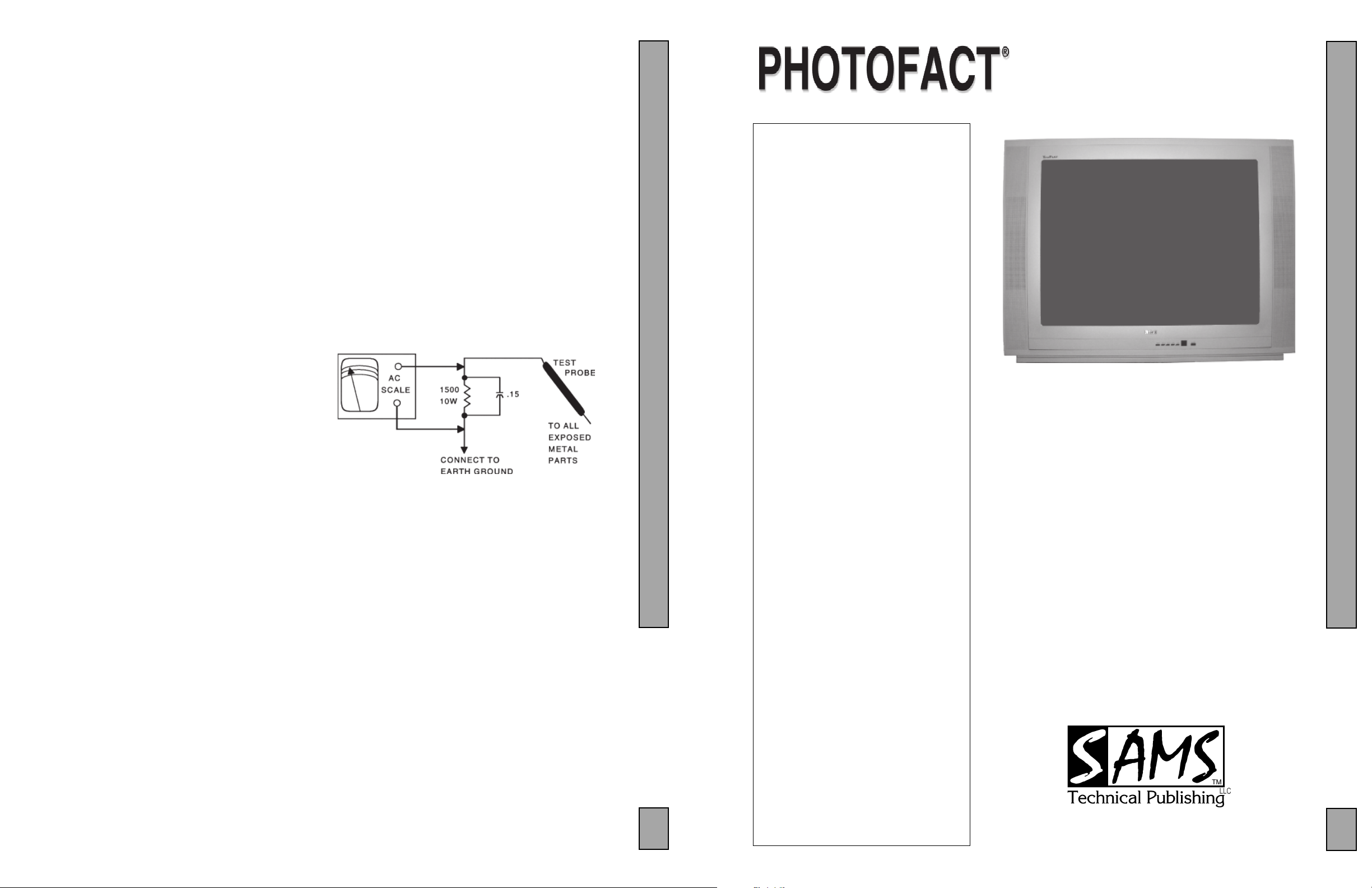
Hot Leakage Current Check
Plug the AC cord directly into an AC outlet. DO NOT use an isolation
transformer. Use a 1500 ohms, 10W resistor in parallel with a .15µF
capacitor to connect between any exposed metal parts on the receiver and
a good earth ground. (See figure below.) Use an AC voltmeter with at
least 5000 ohms per volt sensitivity to measure the voltage across the
resistor. Check all exposed metal parts and measure voltage at each point.
Voltage measurements should not exceed .75VAC, 500µA. Any value
exceeding this limit constitutes a potential shock hazard and must be
corrected. If the AC plug is not polarized, reverse the AC plug and repeat
exposed metal part voltage measurement at each point.
INDEXINDEX
INDEX
INDEXINDEX
SET 5303
GridTrace Location
Main Board ....................................... 3
Comb Filter Board ............................3
Important Parts Information ..................... 4
Miscellaneous Adjustments ..................... 1
Parts List ...................................................4
Placement Chart ....................................... 1
Safety Precautions .................................... 1
Schematic Component Location ..............1
Schematic Notes .......................................2
Schematics
Audio ................................................. 3
CRT ................................................... 2
Power Supply .................................... 2
System Control .................................. 2
Television .......................................... 2
Video Switching/Comb Filter ...........3
Service Mode Chart ................................. 1
Test Equipment.........................................3
Tuner Information ....................................1
5303
Technical Service Data
RCA
Model 27V412T (Chassis M134C)
Representative Model
Essential coverage
for servicing a television receiver...
Schematics
The listing of any available replacement part herein in no case constitutes a recommendation, warranty, or guarantee by
SAMS Technical Publishing, LLC as to the quality and suitability of such replacement part. The numbers of the listed parts
have been compiled from information furnished to SAMS Technical Publishing, LLC by the manufacturers of the specific
type of replacement part listed.
Reproduction or use, without express permission, of editorial or pictorial content, in any manner, is prohibited. No patent
liability is assumed with respect to the use of the information contained herein.
© 2007 SAMS Technical Publishing, LLC
9850 E. 30th St.
Indianapolis IN 46229
www.samswebsite.com
Printed in the United States of America 5 4 3 2 1 07PF03424
Page 1 SET 5303
!IBCGC|05303U
5303
MODEL 27V412T (CHASSIS M134C)
For a Complete List of Manuals,
Visit www.samswebsite.com
RCA
Component locations
Parts list
Coverage includes these additional models and chassis:
Models Chassis
24V412T M134C
27V412TYX1 M134C
27V412TYX3 M134C
27V412TYX5 M134C
27V412TYX8 M134C
OCTOBER 2007 SET 5303
5303
4
Page 2

Page 1 SET 5303
MISCELLANEOUS ADJUSTMENTS
HIGH VOLTAGE TEST
High voltage must not be higher than 31.8kV at any beam current.
X RAY PROTECTION TEST
Tune the set to receive a crosshatch signal. Apply an external power supply
to the positive lead of C249 (observe polarity). Slowly increase the voltage
from the supply. The set must shut down and remain off when the voltage
reaches 30V.
B+
Tune the set to receive a crosshatch signal, set the preset picture mode to
normal, and adjust VR802 for 130V ±0.5V at the positive lead of C422.
RF AGC
The RF AGC is factory preset at the time of manufacture for optimum
operation over a wide range of RF signal input conditions and should not
need readjustment, unless there is cable TV adjacent channel interference
or picture bending or channel 6 color beats because of excessive RF signal
input, this can occur if the receiver is located too close to the transmitting
tower. The signal should be attenuated at the antenna to reduce the signal
to a satisfactory level.
NOTE: Adjusting the RF AGC to extreme limits of its parameters unusually provides a poor signal to noise ratio.
SCREEN
Tune the set to receive a crosshatch signal, set the preset picture mode to
normal and set all of the picture controls (brightness, contrast, etc) to
midrange. Enter the service mode and preset the menu 1 values. Set RC,
GC, and BC to 80, GD and BD to 40. While still in the service mode, press
the input button on the remote and the vertical will collapse. Adjust the
screen control to produce a dim horizontal line on the CRT.
COLOR TEMPERATURE
Test point Display
Adjust: Menu 1 RC Red Cutoff
Menu 1 GC Green Cutoff
Menu 1 BC Blue Cutoff
Menu 1 GD Green Drive
Menu 1 BD Blue Drive
Set color picture temperature to normal and set all of the picture controls
(brightness, contrast, etc) to midrange. Tune the set to receive a gray scale
stairstep test pattern. Enter the service mode and adjust the values for
cutoff and drive controls to obtain proper color tracking, no tinting of black
and white and shades of gray, and color temperature is 9300 degrees - X =
284, Y = 299.
SUB BRIGHTNESS
Tune the set to receive a gray scale stairstep signal from the A/V inputs. Set
picture color temperature to normal, Set all of the picture controls
(brightness, contrast, etc) to midrange. Enter the service mode and select
menu 5. Adjust the value of BRTC sub brightness to just light the second
dark bar, making sure the first bar stays black.
Test point Display
Adjust: Menu 3 HPOS6 H Position
Menu 3 PARA6 H Parabola
Menu 3 TRAP6 H Trapazoid
Menu 3 HSIZE6 H Size
Menu 3 CNRT6 H Corner Top
Menu 3 CNRB6 H Corner Bottom
Menu 2 HIGHT6 Height
Menu 2 VLIN6 Linearity
Menu 2 VP60 Vertical Center
Menu 2 VSC6 Vert S Correct
NOTE: Confirm correct convergence and purity before adjusting geometry.
Tune the set to receive a circular test pattern to make visual geometry
adjustments. Enter the service mode. Adjust menu 2 and menu 3 values for
the least amount of geometric distortion approximately 7% overscan.
SERVICE MODE
NOTE: Pressing the 1 and input buttons on the remote will shut the set
down if you are in the service mode.
To enter the service mode, press and hold the volume down button on the
set while pressing the info/del button on the remote. Menus 1 thru 10 can
be accessed directly using the remote keypad number buttons. For menu 11
press the 1 and notepad buttons on the remote; menu 12 press the 1 and
caps buttons on the remote; menu 13 press 1 and info/del buttons on the
remote; menu 14 press 1 and sleep buttons on the remote; menu 15 press 1
and calendar buttons on the remote; 16 press 1 and insert buttons on the
remote; menu 17 press 1 and FAV buttons on the remote; menu 18 press 1
and go back buttons on the remote. If any of the service mode menu items
have been adjusted, press the sound button to save the settings, and exit the
service mode.
ITEM SETTING
Menu 1
FAC01
RC 76
GC 86
BC 7B
GD 33
BD 2E
Menu 2
FAC02
HIGHT6 19
VP60 07
VLIN6 0A
VSC6 0A
VBLK6 0A
VCEN6 2B
Menu 3
FAC03
HPOS6 13
PARA6 1C
TRAP6 22
HSIZE6 1F
CNRT6 0A
CNRB6 09
VEHT6 03
HEHT6 03
Menu 4
FAC04
CNTX 7F
CNTN 08
BRTX 20
BRTN 20
COLX 35
COLN 00
TNTX 30
TNTN 30
Menu 5
FAC05
BRTC 3C
COLC 23
COLP 00
SCOL 07
SCNT 06
CNTC 4C
TNTCT 37
TNTCV 37
SERVICE MODE CHART
ITEM SETTING
Menu 6
FAC06
ST3 20
SV3 20
SV4 19
SVD 19
ASSH 07
SHPX 10
SHPN 2A
Menu 7
FAC07
MOD1 60
MOD2 B0
MOD3 70
OPT 36
OPTM1 C1
OPTM2 00
HDCNT 00
HSTOP FF
Menu 8
FAC08
RFAGC 26
BRTS 00
OSD 21
OSDF 53
CCD OSD 4A
CCD OSDF 65
TXCX 1F
RGCN 16
Menu 9
FAC09
V01 46
V25 5A
V50 65
V100 7F
VOLMAX 32
CURTCEN A5
GATE 2A
VOL-OUT 73
Menu 10
FAC10
MODE4 22
MODE5 0B
MODE6 1E
MODE7 C4
MODE8 2D
MODE8 C2
ITEM SETTING
Menu 11
FAC11
MPB STR 43
MPB HMC 0D
MPB HP 07
MPB LP 11
MPB LIM 00
SUB FRE 28
SUB HP 02
VOL MAI 00
Menu 12
FAC12
SVM 05
SVM1 05
OSD2 20
OSDF2 64
PYNX 28
PYNN 18
PYXS 22
PYNS 10
Menu 13
FAC13
CLTM 4F
CLVO 48
CLVS 4F
ABL 27
DCBS 12
FLGO 82
FLG1 0D
Menu 14
FAC14
HAFC 09
AGCC 1C
NOIS 01
ONTM 08
NSHP 1A
PVLVL 80
PLMT 80
ITEM SETTING
Menu 15
FAC15
RC-C FC
GC-C 02
BC-C 00
GD-C FD
BD-C 0A
Menu 16
FAC16
RC-W 04
GC-W 01
BC-W 02
GD-W FB
BD-W E7
YUVGC F7
YUVBC 08
Menu 17
FAC17
D-COL 32
D-BRI 32
D-CON 5A
D-SHP 32
Menu 18
FAC18
S-COL 32
S-BRI 32
S-CON 4B
S-SHP 32
Page 3
SET 5303 Page 1
TUNER INFORMATION
TUNER VOLTAGE CHART
Pin Voltage
(1) AGC 1.8V
(2) VT 0V
(3) GND 0V
(4) SCL 4.0V
(5) SDA 4.4V
(6) VCC 4.8V
(7) VCC 4.8V
(8) NC 0V
(9) 33V 33.0V
(10) NC 0V
(11) IF1 0V
NOTE: Voltages do not change
on different bands.
TUNER TERMINAL GUIDE
(1)
(2)
(3)
(4)
(5)
(6)
(7)
(8)
(9)
(10)
(11)
Page 4

SCHEMATIC COMPONENT LOCATION GUIDE
C008 E26
C01 B17
C021 C24
C022 C24
C025 B24
C026 C23
C027 C26
C028 B23
C029 B24
C030 D26
C031 C26
C032 C26
C033 B26
C034 B26
C041 B26
C043 B26
C070A B25
C101 C4
C104 A23
C105 B1
C106 B1
C107 B2
C108 C3
C109 B3
C209 D16
C210 D16
C211 D15
C211 D15
C212 D15
C213 C10
C214 C11
C216 C12
C217 C11
C218 C13
C219 C12
C220 C12
C221 B4
C223 B5
C224 C6
C225 C6
C226 C5
C227 C5
C228 B5
C229 B8
C230 D2
C231 E2
C233 C6
C234 C6
C235 C14
C236 D3
C237 D3
C238 B9
C239 B10
C241 B10
C242 B9
C243 B10
C244 D1
C245 D1
C246 D4
C247 D1
C248 D1
C249 E15
C250 C12
C251 C11
C254 A7
C260 C22
C261 C24
C262 C24
C263 D23
C264 D24
C266 A23
C280 C14
C281 C14
C301 E23
C302 D7
C303 E23
C304 D6
C305 D8
C306 E6
C308 E22
C309 D8
C311 E3
C315 E2
C401 E8
C402 E7
C403 E7
C411 E9
C412 E9
C413 E9
C414 E9
C415 E4
C419 D10
C422 A23
C431 E22
C432 E24
C433 E21
C435 E21
C441 E22
C442 E23
C443 E15
C451 E13
C501 A30
C502 C30
C503 B30
C504 E23
C505 C31
C506 C24
C508 C31
C509 C24
C624 B46
C625 B46
C626 A44
C627 A44
C630 A44
C631 A44
C634 D46
C661 D45
C801 A17
C802 A18
C803 A19
C804 A19
C804A A19
C805 A19
C805A B18
C806 A20
C807 A20
C810 C19
C811 C19
C812 C19
C813 C18
C814 C19
C815 C20
C820 C21
C821 D22
C822 D22
C826 A21
C827 A22
C828 A21
C829 B19
C830 C21
C831 C22
C832 C22
C833 B23
C834 E18
C835 B17
C836 C18
C840 B20
C902 C33
C903 B34
C904 C42
C905 C42
C908 A34
C909 D41
C910 D41
C911 D24
C912 D24
C913 B34
C914 B34
C915 B44
C916 C44
C924 D33
C925 D33
C926 D35
C927 B45
C928 B45
C929 D24
C930 D24
C1001 E44
C1002 E44
C1004 A43
C1005 A43
C1006 E43
C1008 E44
C1009 E43
C1010 E43
C1011 E44
C1012 B42
C1013 B43
C1014 B42
C1015 A43
C1016 B41
C1017 D42
C1018 E42
C1019 E43
C1023 B44
C1024 C44
C1025 B42
C1031 C43
C1033 C44
C1034 C44
C1035 B42
C1036 B42
C1037 A43
C1038 A43
C1201 B36
C1202 B36
C1203 B36
C1204 B36
C1205 D24
C1206 D24
C1211 D38
C1212 D38
C1213 D39
C1214 D39
C1215 B38
C1216 C38
C1217 C38
C1218 C38
C1219 C38
C1220 B38
C1221 B38
C1222 D39
C1223 D39
C1224 D38
C1225 D38
C1229 D39
C1230 D39
C1231 B39
C1233 C39
C1234 C38
C1235 C38
C1236 B38
D001 D25
D01 B17
D02 B17
D101 A23
D202 B16
D203 C16
D204 B16
D205 C14
D206 E2
D207 C12
D208 E14
D209 E14
D210 E15
D211 C11
D212 C11
D213 C11
D214 C13
D215 D16
D262 E15
D301 D7
D303 E3
D304 E2
D309 D9
D310 D8
D410 E4
D411 E10
D412 E10
D420 E11
D431 E22
D432 E21
D441 E22
D501 C29
D502 C29
D602 D45
D810 C19
D811 C19
D811A C19
D811B C19
D812 C19
D813 C18
D820 D21
D820A D21
D820B D21
D822 A21
D822A A21
D822B A21
D823 C21
D823A C21
D823B C21
D824 B23
D826 E19
D827 C17
D828 C17
D829 C18
D834 B22
D1001A D28
DB801 A19
DEGAUSS A19
F801 A17
IC001 B27
IC101 A26
IC101 B11
IC101 B5
IC101 D1
IC201 C23
IC202 D23
IC301 D6
IC602 A47
IC801 B19
IC802 B18
IC901 A34
IC901 C36
IC1001 A43
IC1201 B38
IR001A A25
J215 D3
J603 E10
J604 E10
J1005 E42
L001 D23
L002 B25
L101 B1
L102 B3
L204 C5
L205 C12
L206 A8
L208 C6
L209 B7
L212 C11
L301 D9
L413 E10
L414 D10
L501 C23
L502 B32
L503 B32
L505 C31
L506 C31
L801 A22
L1001 E43
L1201 B36
L1211 D37
L1212 C37
L1213 D37
L1214 D37
L1215 B38
L1216 C37
L1217 D23
P800 A17
P901 B33
P901 C41
P901 C41
P902 B33
P903 A33
P903 D41
P903 D41
P904 A33
P904 A9
P904 A9
P905 B45
P905 B45
P905 D35
Q007 B23
Q008 D25
Q01 B17
Q033C D28
Q101 B3
Q202 E16
Q203 B6
Q204 B7
Q205 E15
Q208 D16
Q209 D15
Q401 E6
Q402 E14
Q411 E8
Q412 E3
Q413 E4
Q414 E4
Q501 A30
Q502 A30
Q503 C30
Q504 C30
Q505 B30
Q506 B30
Q507 C29
Q601 D45
Q602 D45
Q603 E46
Q820 B22
Q821 B22
Q822 B17
Q823 E19
Q824 E18
Q825 E18
Q901 C42
Q902 C42
Q903 D42
Q904 D42
Q911 D34
Q912 D34
Q913 B44
Q914 B44
Q917 B35
Q918 C27
Q919 C44
Q1003 B41
Q1201 B37
Q1202 B37
Q1203 B37
Q1211 C37
Q1212 E39
Q1213 E39
Q1214 C39
Q1215 C39
Q1218 B39
R001 D26
R003 E27
R004 A26
R005 E25
R006 E26
R01 B17
R02 B17
R010 D27
R023A C25
R024 C23
R024A C25
R025 A27
R025A C25
R026 B27
R026A C25
R027A D25
R030 B23
R031 D25
R032 D25
R033 D25
R033B E28
R033C D27
R0333 C25
R034 D26
R036 C26
R036A C26
R043 C27
R044 B26
R070A B25
R101 B1
R101A C1
R102 C3
R103 B3
R104 B3
R106 B2
R107 B2
R108 B2
R209 D16
R211 D15
R212 D15
R213 D16
R214 B16
R215 C15
R216 B15
R219 C12
R220 C13
R222 C4
R223 C4
R225 A7
R226 A7
R227 C5
R228 D2
R229 E2
R230 E2
R231 E2
R232 B6
R233 B7
R233A B6
R234 B7
R235 B8
R238 D3
R239 C14
R241 D3
R242 B10
R243 B10
R244 D1
R245 D5
R246 D1
R247 D5
R248 B10
R250 E16
R251 E15
R253 E15
R254 E2
R255 E2
R256 E2
R257 E2
R258 B8
R261 E15
R262 C12
R266 A22
R302 D6
R303 D6
R304 D8
R309 D8
R310 D8
R311 D6
R312 D6
R313 D7
R316 E3
R401 E6
R402 E7
R404 E7
R412 E3
R413 E4
R414 E4
R415 E4
R416 E4
R417 E4
R418 E3
R419 D10
R420 E4
R420A E4
R422 D11
R431 E22
R432 E14
R433 E21
R453 E13
R460 E23
R461 A32
R501 A29
R502 A29
R503 A30
R505 C29
R506 C30
R508 C30
R509 C29
R510 B29
R511 B30
R513 B30
R514 D29
R515 C29
R516 B30
R517 C30
R518 A30
R519 A31
R520 C31
R521 B31
R522 D29
R605 D46
R605A D46
R606 D45
R608 A44
R610 D46
R611 B46
R612 A44
R618 E46
R656 D44
R801 A17
R810 B19
R811 B18
R812 C18
R813 C20
R814 C19
R815 C19
R816 D20
R820 D21
R821 A21
R823 C21
R825 D22
R826 B22
R827 B22
R828 E19
R829 B22
R830 C18
R831 B17
R832 E18
R833 C17
R834 C17
R834A C17
R834B C17
R835 C17
R836 E19
R837 E18
R838 E17
R840 B20
R901 C33
R902 B34
R903 B34
R904 C41
R905 A34
R906 C41
R908 A33
R910 D41
R911 D42
R912 D41
R913 D42
R914 B10
R915 A10
R916 C42
R917 C42
R920 D23
R923 D35
R924 B45
R925 B45
R926 B45
R929 C45
R930 D34
R931 D35
R932 B33
R932A D33
R933 D33
R934 B34
R934A D23
R935 D34
R936 D34
R937 D34
R944 C44
R945 C27
R946 B33
R946A B34
R947 B35
R948 B35
R951 D41
R952 D41
R953 C42
R954 C42
R1001 B42
R1002 B42
R1004 D43
R1005 B42
R1006 B41
R1007 B41
R1010 C44
R1011 C44
R1022 B43
R1023 B43
R1201 B36
R1202 B36
R1203 B36
R1204 B37
R1205 B37
R1206 B37
R1207 B37
R1208 B37
R1209 B38
R1211 C38
R1212 C38
R1213 C39
R1215 E39
R1216 E39
R1217 E38
R1218 E39
R1219 E38
R1220 C39
R1221 C39
R1228 B39
R1229 B39
R1232 E39
R1233 C40
R1234 C40
R1236 B37
R1237 B37
RL01 A18
RL01 B18
RT801 A18
RT802 A20
S002A C25
S003A C25
S004A C25
S005A D25
S006A D25
S008 C25
S501 A32
S501 B31
S501 B31
S501 B31
S501 B31
S501 C31
S501 C31
T401 E7
T402 D12
T402 D21
T801 A17
T802 A18
T803 A20
TU101 B2
V801 B32
VR802 C17
W601 A48
W602 B48
X001 C26
X201 B7
X202 A7
X1001 E44
Z101 B3
RCA MODEL 27V412T (CHASSIS M134C)
SET 5303 Page 1
Page 5
Page 2 SET 5303
Page 6

SET 5303 Page 2
Page 7

Page 2 SET 5303
PHILIPS MODEL 32PT5441/37 (CHASSIS L04.1UAA)
Page 8

RCA MODEL 27V412T (CHASSIS M134C)
PHILIPS MODEL 32PT5441/37 (CHASSIS L04.1UAA)
SET 5303 Page 2
Page 9

Page 3 SET 5303
Page 10

SET 5303 Page 3
Page 11

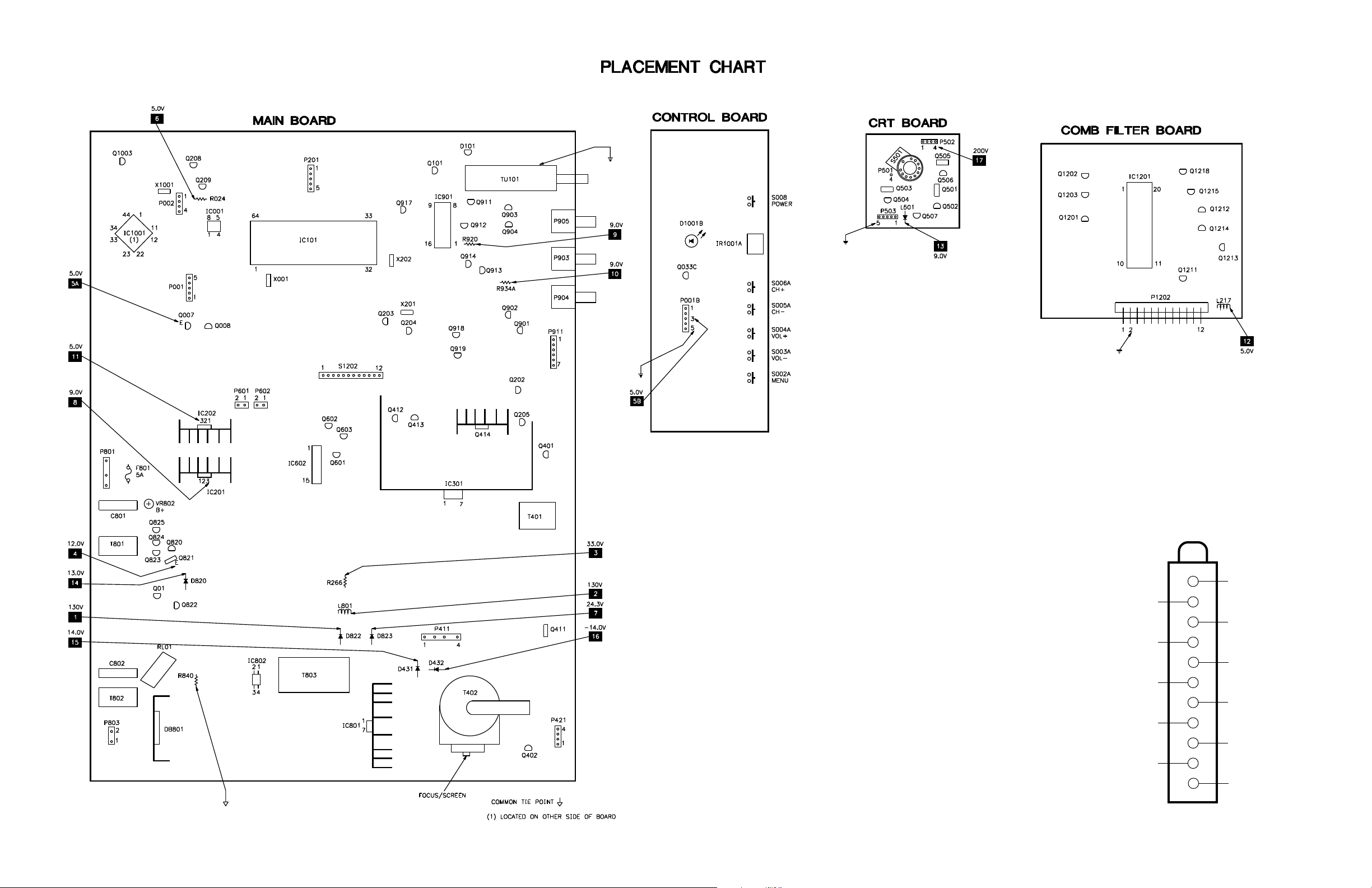
MAIN BOARD
MAIN BOARD, GRIDTRACE LOCATION GUIDE
C008 B5
C01 L2
C021 C4
C022 C4
C025 B5
C026 B5
C027 D4
C028 E3
C029 E4
C030 E5
C031 E5
C032 E5
C033 E5
C034 E5
C041 D5
C043 D4
C101 A12
C104 A10
C105 A11
C106 A11
C107 A10
C108 B9
C109 B9
C209 A3
C210 A4
C211 A4
C212 A4
C213 B6
C214 B6
C216 B6
C217 B6
C218 B6
C219 B7
C220 B8
C221 B7
C223 C7
C224 B8
C225 B7
C226 C8
C227 B8
C228 C8
C229 D9
C230 C8
C231 D8
C233 D8
C234 D8
C235 D7
C236 D7
C237 D7
C238 D8
C239 E7
C241 D7
C242 C8
C243 D7
C244 D6
C245 E6
C246 D6
C247 D6
C248 D6
C249 G12
C250 H9
C251 H10
C254 B8
C261 G4
C262 H4
C263 G2
C264 F2
C266 J7
C280 E7
C281 E8
C301 I8
C302 I10
C303 I10
C304 H9
C305 I9
C306 J9
C308 I9
C309 L9
C311 L8
C315 J8
C401 I12
C402 J10
C403 I12
C411 L11
C412 L11
C413 K12
C414 L11
C415 H10
C419 J11
C422 L7
C431 M7
C432 M7
C433 L8
C435 M7
C441 O12
C442 O12
C443 O11
C451 P12
C624 I5
C625 I5
C626 I7
C627 I7
C630 H5
C631 H5
C634 H7
C661 G5
C801 I1
C802 M1
C803 O1
C804 O2
C804A N2
C805 O3
C805A N3
C806 P4
C807 P3
C810 O6
C811 O6
C812 P5
C813 P6
C814 P5
C815 O6
C820 L4
C821 K4
C822 K4
C826 L7
C827 K6
C828 L6
C829 M4
C830 L5
C831 K5
C832 K5
C833 L3
C834 K3
C835 M3
C836 M3
C840 N3
C902 F11
C903 D11
C904 F11
C905 E11
C908 D11
C909 C11
C910 C11
C911 E10
C912 E10
C913 D11
C914 D11
C915 F10
C916 F10
C924 B10
C925 B10
C926 B11
C927 B11
C928 B11
C929 C10
C930 C10
C1001 B2
C1002 B2
C1004 B2
C1005 B2
C1006 B2
C1008 B1
C1009 B1
C1010 A1
C1011 B1
C1012 A1
C1013 A1
C1014 A2
C1015 C1
C1016 A2
C1017 D2
C1018 C1
C1019 D1
C1023 D2
C1024 D2
C1025 A2
C1031 C2
C1033 B2
C1034 B2
C1035 C2
C1036 D2
C1037 D1
C1038 D1
D001 E4
D01 L3
D02 L3
D101 A10
D202 B6
D203 A6
D204 A6
D205 E7
D206 F9
D207 B7
D208 E6
D209 E6
D210 G12
D211 H10
D212 H10
D213 H9
D214 D9
D215 A4
D262 H12
D301 I9
D303 J8
D304 J7
D309 J8
D310 J9
D410 G11
D411 K10
D412 K11
D420 O11
D431 M8
D432 L8
D441 O12
D602 G4
D810 P5
D811 O5
D811A O5
D811B O6
D812 P6
D813 P6
D820 L4
D820A K4
D820B L4
D822 L6
D822A L6
D822B L6
D823 L5
D823A L5
D823B L5
D824 H4
D826 J3
D828 M3
D829 M4
D834 K3
DB801 O2
F801 H1
IC001 C4
IC101 C5
IC201 I3
IC202 G3
IC301 J10
IC602 H6
IC801 O7
IC802 N4
IC901 C9
IC1001* C1
J215 G8
J603 H7
J604 G7
J1005 B2
L001 F4
L002 E5
L101 B9
L102 B9
L204 B8
L205 B8
L206 C8
L208 E8
L209 E8
L212 B6
L413 I11
L414 J10
L801 K6
L1001 D2
P001 D3
P201 A6
P411 L9
P421 O12
P601 G4
P602 G4
P801 H1
P803 P1
P903 C12
P904 D12
P905 B12
P911 F12
Q007 E3
Q008 E4
Q01 L3
Q101 A9
Q202 G11
Q203 E8
Q204 E9
Q205 G12
Q208 A4
Q209 B4
Q401 H12
Q402 P12
Q411 L12
Q412 G8
Q413 G9
Q414 H11
Q601 H7
Q602 G6
Q603 H7
Q820 K3
Q821 K3
Q822 M3
Q823 K3
Q824 K3
Q825 J3
Q901 E11
Q902 E11
Q903 C11
Q904 C11
Q911 B10
Q912 C10
Q913 D10
Q914 D10
Q917 C8
Q918 E10
Q919 E10
Q1003 A1
R001 E4
R003 B4
R004 E4
R005 B4
R006 B5
R01 L2
R02 L3
R010 D4
R024 B4
R025 C4
R026 C4
R030 F4
R031 F4
R032 E4
R033 D5
R034 E5
R036 D4
R036A D4
R043 D4
R044 D5
R101 A11
R101A A11
R102 B9
R103 B9
R104 A9
R106 A9
R107 A9
R108 A9
R209 A4
R211 B4
R212 A4
R213 A4
R214 B6
R215 B6
R216 B6
R219 B6
R220 B6
R222 A7
R223 A7
R225 D8
R226 C8
R227 C8
R228 C8
R229 D8
R230 D8
R231 D8
R232 D8
R233 E8
R233A D8
R234 E8
R235 E9
R238 E8
R239 E7
R241 E7
R242 E7
R243 E7
R244 E7
R245 D6
R246 D6
R247 E6
R248 D7
R250 G12
R251 G12
R253 G12
R254 E8
R255 E8
R256 F9
R257 F9
R258 D8
R261 G12
R262 H9
R266 J7
R302 H9
R303 H8
R304 J9
R309 K9
R310 J9
R311 I10
R312 I10
R313 J9
R316 M8
R401 H12
R402 J11
R404 K8
R412 H8
R413 H8
R414 H10
R415 H11
R416 G11
R417 H9
R418 G8
R419 K9
R420 H9
R420A H10
R422 L8
R431 M8
R432 M8
R433 M8
R453 P11
R460 N12
R461 P12
R605 H5
R605A H7
R606 H6
R608 I5
R610 H7
R611 I5
R612 I7
R618 D4
R656 G5
R801 J1
R810 P2
R811 P6
R812 P6
R813 O5
R814 O5
R815 P6
R816 P6
R820 L4
R821 L7
R823 L5
R825 K4
R826 J6
R827 J3
R828 J6
R829 K3
R830 M4
R831 M3
R832 K3
R833 M4
R834 J3
R834A J3
R834B J3
R835 I3
R836 L3
R837 K3
R838 I2
R840 N3
R901 F11
R902 E12
R903 D10
R904 E11
R905 D10
R906 E11
R908 D11
R910 C11
R911 C11
R912 C11
R913 C11
R914 E6
R915 E6
R916 F11
R917 D11
R920 C10
R923 C10
R924 B11
R925 B11
R926 B10
R929 D10
R930 C10
R931 C10
R932 D11
R932A E10
R933 B10
R934 D10
R934A E10
R935 B10
R936 C10
R937 C10
R944 D9
R945 D9
R946 D8
R946A C9
R947 C8
R948 B8
R951 D11
R952 D11
R953 E11
R954 E11
R1001 C2
R1002 D2
R1004 D1
R1005 A1
R1006 A2
R1007 A2
R1010 C2
R1011 B2
R1022 C1
R1023 D1
RL01 M1
RT801 P1
RT802 P3
S1202 F6
T401 J12
T402 N10
T801 K1
T802 N1
T803 N5
TU101 A11
VR802 J2
X001 D5
X201 E8
X202 D8
X1001 B2
Z101 B7
* Located on
other side of
board.
Page 3 SET 5303
SET 5303 Page 3
Page 12

COMB FILTER BOARD
TEST EQUIPMENT
Test equipment listed by participating manufacturer illustrates
typical or equivalent equipment used by Sams engineers to obtain
measurements. This equipment is compatible with most types used
by field service technicians.
Equipment Sencore No.
Oscilloscope SC3100
Generators
RGB CM2125
Multiburst Signal VG91
Color Bar VG91
TV Stereo VG91
Digital VOM SC3100
Frequency Meter SC3100
Hi-Voltage Probe HP200
Accessory Probes TP212
Isolation Transformer PR570
Capacitance Analyzer LC102
CRT Analyzer CR7000
AC Leakage Tester PR570
Inductance Analyzer LC102
Flyback Yoke Tester TVA92
Field Strength Meter SL753
Transistor Tester TF46
Horizontal Analyzer HA-2500
Video Analyzer VG91, TVA92
RCA MODEL 27V412T (CHASSIS M134C)
COMB FILTER BOARD, GRIDTRACE LOCATION GUIDE
C1201 F7
C1202 G2
C1203 H7
C1204 H6
C1205 B5
C1206 B6
C1211 F2
C1212 F2
C1213 F3
C1214 F3
C1215 F4
C1216 G5
C1217 F5
C1218 G6
C1219 F6
C1220 D6
C1221 D5
C1222 D4
C1223 D5
C1224 D3
C1225 D4
C1229 E1
C1230 E1
C1231 C1
C1233 B3
C1234 F6
C1235 E6
C1236 F3
IC1201 E2
L1201 G7
L1211 F1
L1212 H5
L1213 H6
L1214 D2
L1215 C5
L1216 E5
L1217 B6
P1202 F7
Q1201 H4
Q1202 G2
Q1203 H3
Q1211 C6
Q1212 B3
Q1213 A5
Q1214 B4
Q1215 C3
Q1218 C2
R1201 F7
R1202 H7
R1203 H5
R1204 G4
R1205 H2
R1206 H3
R1207 H1
R1208 H1
R1209 G3
R1211 E6
R1212 E6
R1213 D4
R1215 A6
R1216 A7
R1217 A4
R1218 B4
R1219 A3
R1220 D3
R1221 B1
R1228 D1
R1229 B1
R1232 B5
R1233 B1
R1234 A1
R1236 B5
R1237 C6
SET 5303 Page 3
Page 13

Page 4 SET 5303
PARTS LIST
Item No. Type No. Mfr. Part No. Notes
D001 5.1HSB 268334 -
D01, 02 1N4148 266885 -
D101 (1) CW574CD 266892 -
D101 (2)(3)(4)(5) UPC574J 270921 -
D202 Thru
D206 1N4148 266885 -
D207 - 266890 -
D208 1N4148 266885 -
D209 - 268335 -
D210 - 268336 -
D211, 12 1N4148 266885 -
D213 - 266888 -
D214, 15 1N4148 266885 -
D262 1N4148 266885 -
D301 1N4001 266883 -
D303 - 266891 -
D304 FR104 266880 -
D309 BZV85-C51 268337 -
D310 1N4148 266885 -
D410 1N4148 266885 -
# D411 (1) BY228 266879 -
# D411 (2)(3)(4)(5) - 271009 -
# D412 FR104 266880 -
D420 (4)(5) 1N4001 266883 -
D420 (1)(2)(3) FR104 266880 -
D431, 32 FR104 266880 -
D441 FR104 266880 -
D501, 02 1N4148 266885 -
D602 1N4148 266885 -
D810, 11 FR104 266880 -
D812 1N4148 266885 -
D813 - 266890 -
# D820 RU4YX 268338 -
D822 RU4AM 268339 -
D823 (1)(6) RU4YX 268338 -
D823 (2)(3)(4)(5) SR3100 270876 -
D824 1N4001 266883 -
D826 - 266891 -
D827 1N4148 266885 -
D828 BZX79B6V2 270380 -
D829 1N4148 266885 -
D834 - 268340 -
D1001A - 268440 -
Item No. Type No. Mfr. Part No. Notes
DB801 D3SB60 268341 -
IC001 MC24-08P 266906 -
IC101 (1) TMPA8859CSNG 268344 -
IC101 (2)(3)(4)(5) TCL-A27V02-T0 270923 -
IC201 (1)(6) L7809CV 266912 -
IC201 (2)(3)(4)(5) L7809 270922 -
IC202 (1)(6) L7805CV 257704 -
IC202 (2)(3)(4)(5) L7805CV 270856 -
IC301 STV8172 270381 -
IC602 TDA7266SA 268347 -
IC801 STRW6735 268348 -
# IC802 PS2561L1-1V 268349 -
IC901 4052 268350 -
IC1001 MSPP3425G 268343 -
IC1201 TC90A49P 268345 -
J310 1N4148 266885 -
L501 1N4148 266885 -
Q007 2SC1815Y 266579 -
Q008 2SA1015Y 266899 -
Q01 - 268364 -
Q033C 2SC1815Y 266579 -
Q101 2SC3779D 266902 -
Q202, 03, 04 2SC1815Y 266579 -
Q205 2SA1015Y 266899 -
Q208 2SA817AY 266603 -
Q209 PDTC124ES 266897 -
# Q401 2SC2482 266900 -
Q402 2SC1815Y 266579 -
# Q411 3DD3402 268428 -
Q412, 13 2SA1015Y 266899 -
Q414 IRF630MFP 268367 -
Q501 2SC4544 208434 -
Q502 2SC1815Y 266579 -
Q503 2SC4544 208434 -
Q504 2SC1815Y 266579 -
Q505 2SC4544 208434 -
Q506 2SC1815Y 266579 -
Q507 2SA562TM-O 268369 -
Q601 2SC1815Y 266579 -
Q602 2SA1015Y 266899 -
Q603 PDTC124ES 266897 -
Q820 - 268370 -
Q821 2SC4544 208434 -
Page 14

PARTS LIST continued
SET 5303 Page 4
Item No. Type No. Mfr. Part No. Notes
Q822 Thru
Q825 2SC1815Y 266579 -
Q901 Thru
Q904 2SC1815Y 266579 -
Q911 2SC1815Y 266579 -
Q912 2SA1015Y 266899 -
Q913, 14, 17 2SC1815Y 266579 -
Q918, 19 PDTC124ES 266897 -
Q1003 2SC1815Y 266579 -
Q1201 2SC1815Y 266579 -
Q1202 2SA1015Y 266899 -
Q1203 2SC1815Y 266579 -
Q1211 2SA1015Y 266899 -
Q1212 2SC1815Y 266579 -
Q1213, 14 2SK362-Y 268365 -
Q1215, 18 2SA1015Y 266899 -
R212 1N4148 266885 -
Item No. Function/Rating Mfr. Part No. Notes
# C411 .0039 5% 1.6kV 268312 -
.0036 5% 1.6kV 268311 -
.0033 5% 1.6kV 268449 -
# C412 .0082 5% 1.6kV 268436 -
.0068 5% 1.6kV 268424 -
# C413 .027 5% 400V 270395 -
.022 5% 400V 268313 -
# C414 .0076 5% 1.6kV 268314 -
.0082 5% 1.6kV 268436 -
.0056 5% 1.6kV 270396 -
.0072 5% 1.6Kv 268450 -
C415 4.7µF 20% 50V NP 268315 -
# C419 .47 5% 400V 268425 -
.51 5% 400V 270402 -
.56 5% 400V 270927 -
.33 5% 400V 268397 -
C505 .001 10% 2kV 268322 -
# C801, 02 .22 20% 250VAC 270379 -
.22 20% 275VAC 266326 -
C804 .0047 +80% -20% 250VAC 266984 -
# C804A 470pF 10% 400VAC 266983 -
C805 .0047 +80% -20% 250VAC 266984 -
# C805A 470pF 10% 400VAC 266983 -
C815 .0015 10% 2kV 268330 -
Item No. Function/Rating Mfr. Part No. Notes
C826 470pF 10% 2kV 268439 -
# C840 .0022 20% 400VAC 266982 -
C1001, 02 3.3pF ±.25pF 50V NPO 266971 -
D811A, B Ferrite Bead 267016 -
D820A, B Ferrite Bead 268283 -
D822A, B Ferrite Bead 268283 -
D823A, B Ferrite Bead 268283 -
# DEGAUSS (1) Degaussing 268431 -
# DEGAUSS (2)(3)(4)(5) Degaussing 263503 -
# DEGAUSS (6) Degaussing 268466 -
# F801 Fuse 268342 5Amp
F801A, B Fuse Holder 267064 For F801
IR001A Receiver 270382 Remote
J603, 04 2.2µH 270398 -
J1005 22µH 267008 -
L001 Ferrite Bead 270407 -
L002 10µH 267010 -
L101 47µH 268351 -
L102 1µH 267007 -
L204, 05 06, 08 22µH 267013 -
L209, 12 10µH 267010 -
L301 Ferrite Bead 268352 -
L413 600µH 268353 -
# L414 (1)(2)(4)(6) 24µH 270399 -
# L414 (3)(5) 18µH 268427 -
L501 1N4148 266885 -
L502 10µH 267011 -
L503 (1)(2)(3)(4)(5) 5.6µH 268355 -
L503 (6) 10µH 267011 -
L505, 06 Ferrite Bead 267016 -
L801 100µH 267012 -
L1001 22µH 267008 -
L1201 10µH 267010 -
L1211 Thru
L1215 10µH 267010 -
L1216 .6µH 267009 -
L1217 10µH 267010 -
# P800 (1)(6) Line Cord 268396 Polarized
# P800 (2)(3)(4)(5) Line Cord 268457 Polarized
P901 Jack 267046 Assembly
P902 Jack 268360 Video Input
P903 Jack 268360 Assembly
P904 Jack 268361 Assembly
Page 15

PARTS LIST continued
Item No. Function/Rating Mfr. Part No. Notes
P905 Jack 268360 Assembly
R302 3900 1% 1/4W 268381 -
R303 36K 1% 1/4W 268429 -
33K 1% 1/4W 268382 -
R311 10K 1% 1/4W 268385 -
R312 18K 1% 1/4W 268386 -
R404 4700 5% 7W 268390 -
# R516, 17, 18 15K 2W - -
4700 5% 1/6W 266282 -
# R801 1M 20% 1/2W 266940 -
R820 Fuse 268410 5Amp, 250VAC
R821, 23 Fuse 268411 3Amp, 250VAC
R827 4700 5% 5W 268413 -
R834A 6800 1% 1/4W 176634 -
R834B 390 1% 1/4W 266595 -
R835 120K 1% 1/2W 268414 -
# R840 8.2M 1W 266941 -
# RL01 Relay 268417 Degaussing
# RT801 (1)(6) PTC 268418 -
# RT801 (2)(3)(4)(5) PTC 270926 -
# RT802 NTC 266357 -
S002A Switch 267136 Menu
S003A Switch 267136 Volume -
S004A Switch 267136 Volume +
S005A Switch 267136 Channel -
S006A Switch 267136 Channel +
S008 Switch 267136 Power
# S501 Socket 266290 CRT
# T401 Horizontal Drive 266291 -
# T402 (7) Horizontal Output 268419 -
# T801, 02 Line Filter 268420 -
# T803 Power 268421 -
TU101 Tuner 270388 TEDH9-251A
# V801 CRT - -
VR802 330 B+ 270389 -
2000 B+ - -
W601, 02 (1) Speaker 270373 16 Ohms, 8W
W601, 02 (6) Speaker 268472 16 Ohms, 5W
W601, 02 (2)(3)(4)(5) Speaker 271001 60mm X 125mm, 16 Ohms
X001 Crystal 266315 8MHz
X201 Trap 266318 4.5MHz
X202 Filter 266317 4.5MHz
X1001 Crystal 268423 18.432MHz
Item No. Function/Rating Mfr. Part No. Notes
Z101 Filter 266319 SAW
PC Board (4) 270963 Comb Filter
PC Board (2)(5) 270959 CRT
PC Board (3)(4) 270964 CRT
PC Board (2)(3)(4)(5) 270958 IR Receiver
PC Board (2)(3)(4)(5) 270961 Keyboard
PC Board (2)(3)(4)(5) 270962 Side
PC Board (3)(5) 260967 Yoke Adapter
Spacers 267049 Yoke Positioning (3 Used)
Transmitter (2)(3)(4)(5) 265714 Remote, RCR130TB1
Transmitter (1)(6) 270372 Remote
# For SAFETY use only equivalent replacement part.
(1) Used in model 27V412T.
(2) Used in model 27V412TYX1.
(3) Used in model 27V412TYX3.
(4) Used in model 27V412TYX5.
(5) Used in model 27V412TYX8.
(6) Used in model 24V412T.
(7) Screen and focus controls are part of T402.
Important Parts Information
n Parts not listed in the parts list are commonly available at your local electronics parts retailer.
n The parts listed here are those not usually available from a well-stocked supply cabinet or bin.
n On the parts lists, safety items are marked with a # to remind you that only exact replacements are recommended for
these items.
n When ordering parts, state the model number, part number, and description.
Obtaining Parts
Many of these parts are available from your local Sams authorized distributor or the manufacturer of the equipment. Call
Sams for the name of your nearest distributor:
800-428-7267
Page 4 SET 5303
Page 16

RCA MODEL 27V412T (CHASSIS M134C)
RCA MODEL 27V412T (CHASSIS M134C)
SET 5303 Page 4
 Loading...