

Page 1

SBC 1000/2000 Series Configuration Guide
with
Lync 2013 for ThinkTel SIP Trunk
Deployments
Application Notes v1.0
P/N XXX-XXXXX SBC1000
Last Updated: April 24, 2015
Sonus – Network Design Group
Page 2

1 Document Overview ......................................................................... 4
1.1 Overview ............................................................................................................................ 4
2 Introduction ...................................................................................... 5
2.1 Audience ............................................................................................................................ 5
2.2 Requirements ..................................................................................................................... 5
2.3 Reference Configuration ..................................................................................................... 6
Network Topology ........................................................................................................... 6
3 Configuring Sonus SBC 1000 and SBC 2000 Series ...................... 7
3.1 SBC Configuration Diagram ................................................................................................ 7
3.2 External Peer Side SBC Configuration ................................................................................ 7
Node Interfaces ............................................................................................................... 7
SIP profile ..................................................................................................................... 10
Media Profile ................................................................................................................. 11
Signaling Groups ........................................................................................................... 14
Call Routing Table ......................................................................................................... 15
Transformation Tables ................................................................................................... 16
3.3 Internal Side SBC Configuration ........................................................................................ 17
Node Interfaces ............................................................................................................. 17
SIP Profile ..................................................................................................................... 19
Media Profiles ............................................................................................................... 20
Signaling Group............................................................................................................. 22
Sip Server Table ............................................................................................................ 23
Call Routing Table ......................................................................................................... 24
Transformation Tables ................................................................................................... 25
4 Lync Server 2013 Configuration .................................................... 26
4.1 Lync 2013 Configuration Settings ...................................................................................... 26
Adding the SBC to the Lync Server. ................................................................ ............... 26
Adding the SBC to the Lync Server 2013 Routing. ......................................................... 30
5 SBC and Lync 2013 Specific Configurations ................................ 32
5.1 Initial Setup for All Calls .................................................................................................... 32
Calling number manipulation ......................................................................................... 32
Called number ............................................................................................................... 32
5.2 Initiating Transfers with REFER......................................................................................... 33
Call transfer using SIP REFER Method .......................................................................... 33
Sonus – Network Design Group 2 of 35
Copyright © 2015, Sonus and/or its affiliates. All rights reserved.
Page 3

5.3 Initiating Transfers with Re-INVITE.................................................................................... 34
Call transfer using Re-Invite method .............................................................................. 34
5.4 Call Hold ........................................................................................................................... 34
Call Hold using RFC3264 .............................................................................................. 34
5.5 Media System Configuration ............................................................................................. 34
6 Exceptions ...................................................................................... 35
6.1 Lync 2013 Exceptions ....................................................................................................... 35
302 Moved Temporarily ................................................................................................. 35
6.2 SBC1000 Exceptions ........................................................................................................ 35
Fax V.34........................................................................................................................ 35
Sonus – Network Design Group 3 of 35
Copyright © 2015, Sonus and/or its affiliates. All rights reserved.
Page 4

1 Document Overview
This Application Note describes the configuration steps required for the Sonus Session Border Controller (SBC)
1000 and SBC 2000 to interoperate with the Lync 2013 system and a SIP trunk group to PSTN.
The objective of this document is to describe the configuration procedures performed during interoperability
testing of SBC 1000 and SBC 2000 with Lync 2013 Server over SIP trunk to PSTN.
For additional information on Sonus SBC 1000 and SBC 2000 series, visit http://www.sonus.net
For additional information on Lync 2013, visit http://www.microsoft.com
1.1 Overview
The Sonus SBC 1000 and SBC 2000 Session Border Controllers are designed to use the same application
software, boot image, and Survivable Branch Appliance software. The SBCs differ in the number of physical
Ethernet connections and processing power, but otherwise are viewed from a software standpoint as identical.
The reference configuration described in the following sections was tested with an SBC 1000, but is fully
applicable to an SBC 2000.
Sonus – Network Design Group 4 of 35
Copyright © 2015, Sonus and/or its affiliates. All rights reserved.
Page 5

Sonus Equipment
Type
Version
SBC 1000
SBC 1000
4.1 Build 369
3rd Party Equipment
Type
Version
Microsoft Lync 2013
Mediation Server
5.0.8308.420
2 Introduction
This document provides configuration guidance for the Sonus SBC (Session Border Controller) 1000 Series
when connecting to a SIP trunk group and a MS Lync 2013.
The Sonus SBC 1000 and SBC 2000 are Session Border Controllers which connect disparate SIP trunks, SIP
PBXs, and communication applications within an enterprise. The SBC can also be used as a SIP routing and
integration engine.
The Sonus SBC is the point of connection between the SIP trunk group to PSTN and the Lync 2013.
2.1 Audience
This technical document is intended for telecommunication engineers for the purpose of configuring the Sonus
SBC 1000 and SBC 2000, along with aspects of the SIP trunk group coupled with the Lync 2013 product. There
are steps that require navigating third-party and Sonus SBC Graphical User Interface (GUI). Understanding the
basic concepts of IP, routing, and SIP/RTP are necessary to complete the configuration or troubleshooting, if
necessary.
This configuration guide is offered as a convenient reference for Sonus customers. The product specifications
and information contained in this guide are subject to change without notice. All statements, information, and
recommendations in this guide are believed to be accurate, but are presented without warranty of any kind,
express or implied, and are provided “AS IS”. Users must take full responsibility for the application of the
specifications and information in this guide.
Technical support on SBC 1000 and SBC 2000 can be obtained through the following:
Phone: +1 888-391-3434 (Toll-free) or +1 978-614-8589 (Direct)
Web: http://www.sonus.net/company/maintenance/log-trouble-tickets
2.2 Requirements
The following equipment and software was used for the sample configuration provided:
Sonus – Network Design Group 5 of 35
Copyright © 2015, Sonus and/or its affiliates. All rights reserved.
Page 6
2.3 Reference Configuration
Lync 2013
Sonus
SBC 1000
ThinkTel
Interna l IP Network
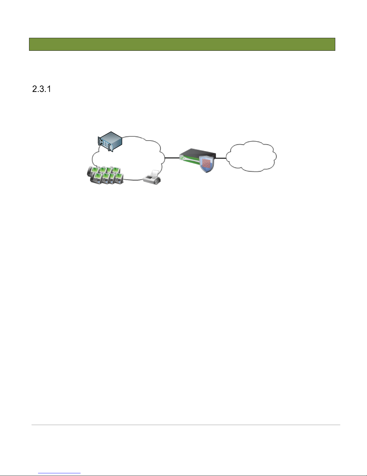
The simulated enterprise site consists of a Lync 2013 and a SIP trunk group to PSTN connected over the SBC
1000. The SBC 1000 was running software version 4.1, Build 369 during testing.
Network Topology
Figure 1: Network Topology
The figure above shows the equipment used for the integration and certification testing. The SBC 1000 is used to
route and facilitate calls between the PSTN and the Lync 2013 system.
The SBC 1000 under test has 2 Ethernet ports configured. The SBC 2000 can have up to 4 physical Ethernet
ports. For more information on Media port deployment options, refer to the SBC 1000 Network Deployment
Guide. Contact your local Sales team for further information or other network connectivity queries with the
Sonus Network Design professional services offerings.
Sonus – Network Design Group
Page 7
3 Configuring Sonus SBC 1000 and SBC 2000 Series
Lync 2013 Signaling Group
Internal
Lync 2013
External
Signaling Group: To/From MS Lync 2013
Call Routing: To Lync 2013
Signaling Group: To/From ThinkTel
Call Routing: To PSTN
10.35 .180.136:5060
SIP over TCP
ThinkTel
10.35 .177.226:5060
208.68.17.52 :5060
216.110.2.235:5060
SIP over UDP
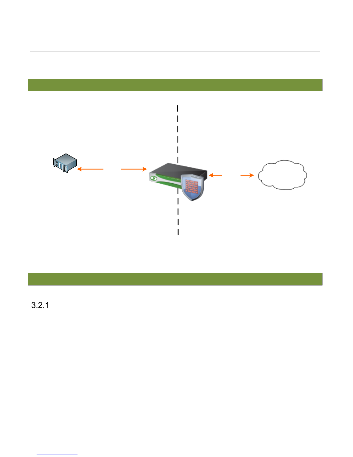
The SBC 1000 and SBC 2000 share a common code base and user interface. In this example, we are using an
SBC 1000.
3.1 SBC Configuration Diagram
3.2 External Peer Side SBC Configuration
The Sonus SBC 1000 allows you to configure the Identification information, Physical Data Layer, and Networking
Layer for the Ethernet ports. If you want to change the IP address, you must configure the associated Logical
Interface or use the Modify Ethernet IP task found under the Tasks tab.
Node Interfaces
Figure 2: SBC 1000 SIP Trunk Diagram
Sonus – Network Design Group
Page 8
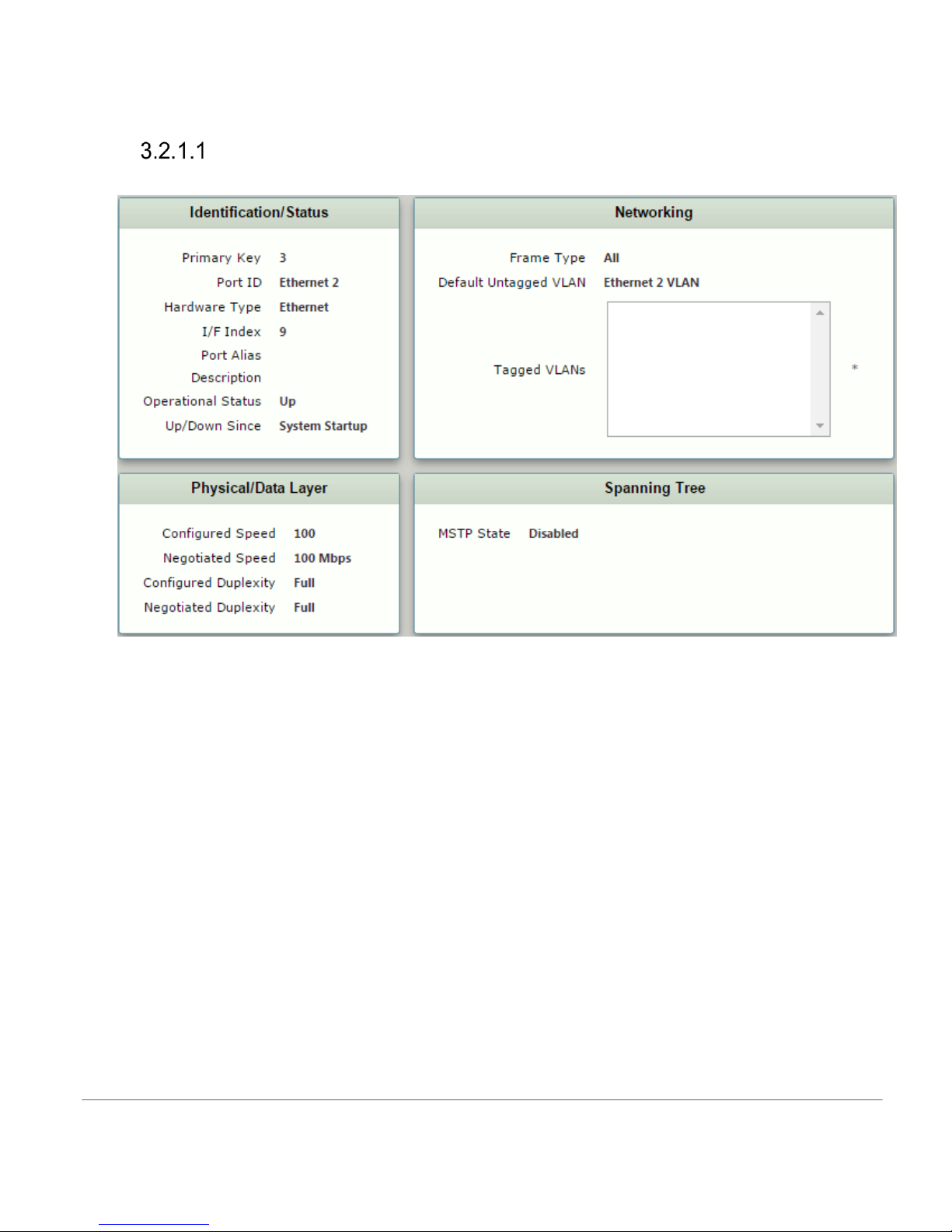
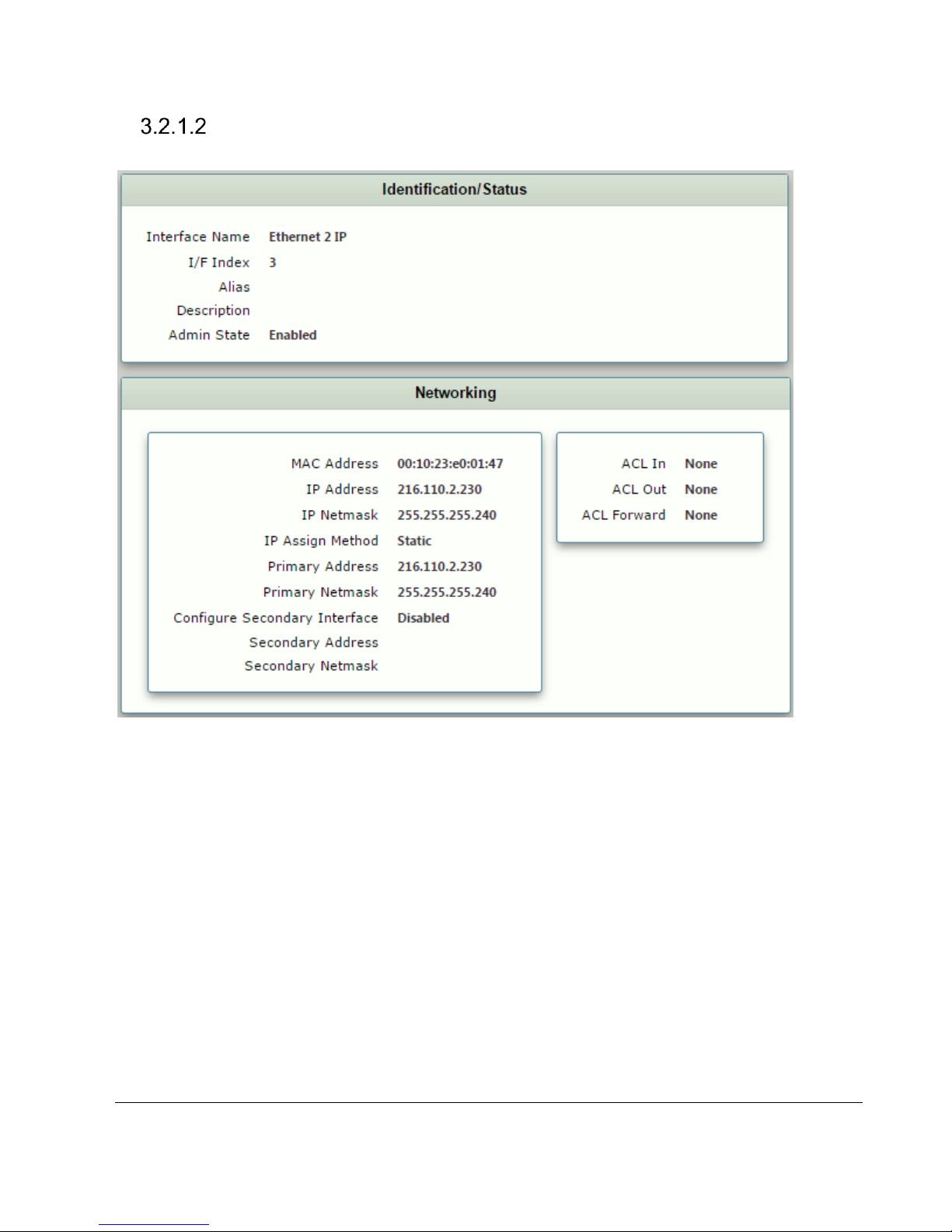
The following sections contain figures that show settings for the Ethernet connection between the Sonus SBC
1000 and Public internet.
Node Ports
Figure 3 External Port
Sonus – Network Design Group
Page 9
Node Interfaces
Figure 4 Logical Interface
Sonus – Network Design Group 9 of 35
Copyright © 2015, Sonus and/or its affiliates. All rights reserved.
Page 10
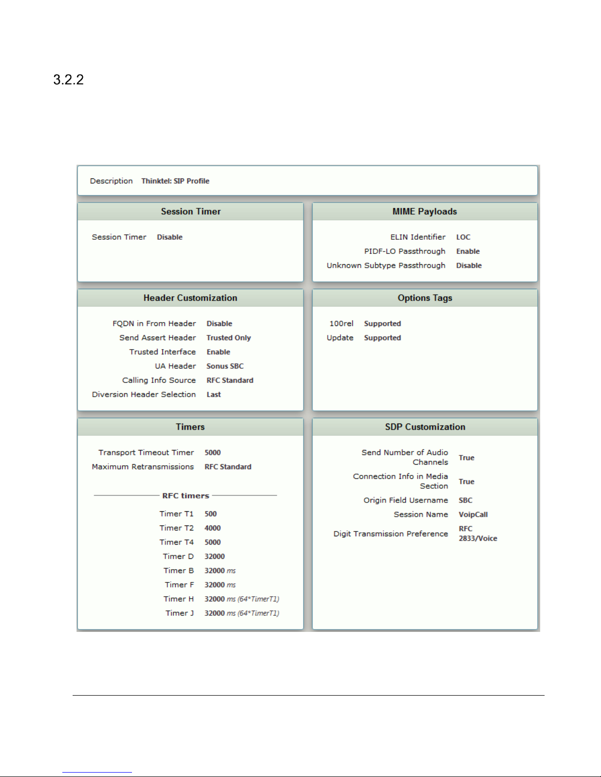
SIP profile
SIP Profiles control how the Sonus SBC 1000/2000 communicates with SIP devices, and control important
characteristics such as: session timers, SIP header customization, SIP timers, MIME payloads, and option tags.
Shown below is the default SIP profile used for the SBC 1000 in this test.
Sonus – Network Design Group 10 of 35
Copyright © 2015, Sonus and/or its affiliates. All rights reserved.
Figure 5: SIP profile
Page 11
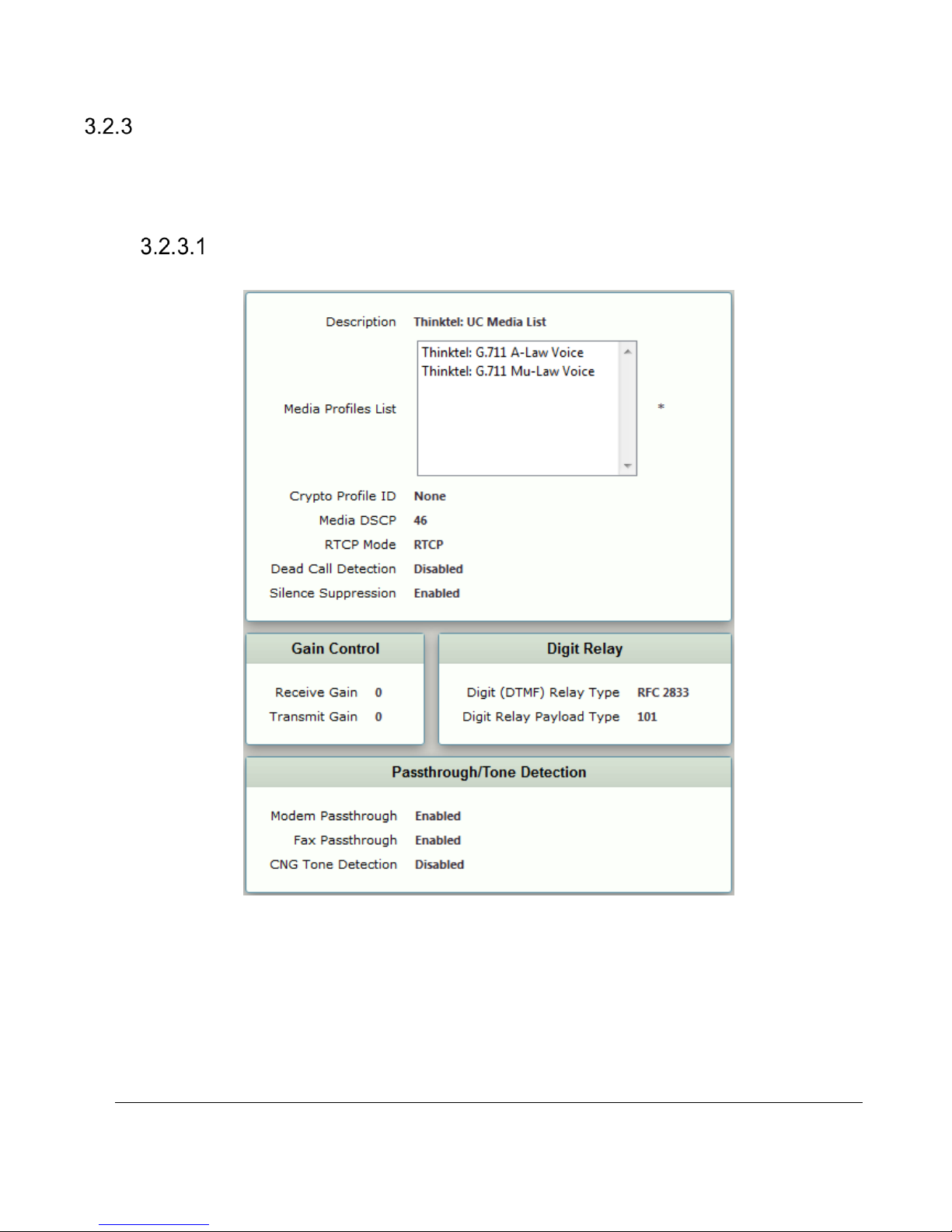
Media Profile
Media Profiles allow you to specify individual voice and fax compression codecs, and their associated settings,
for inclusion in a Media List. Different codecs provide varying levels of compression, allowing one to reduce
bandwidth requirements at the expense of voice quality. For reference, the Media Profile used for the SBC 1000
is shown below.
Media Lists
Sonus – Network Design Group 11 of 35
Copyright © 2015, Sonus and/or its affiliates. All rights reserved.
Figure 6 :Media List
Page 12
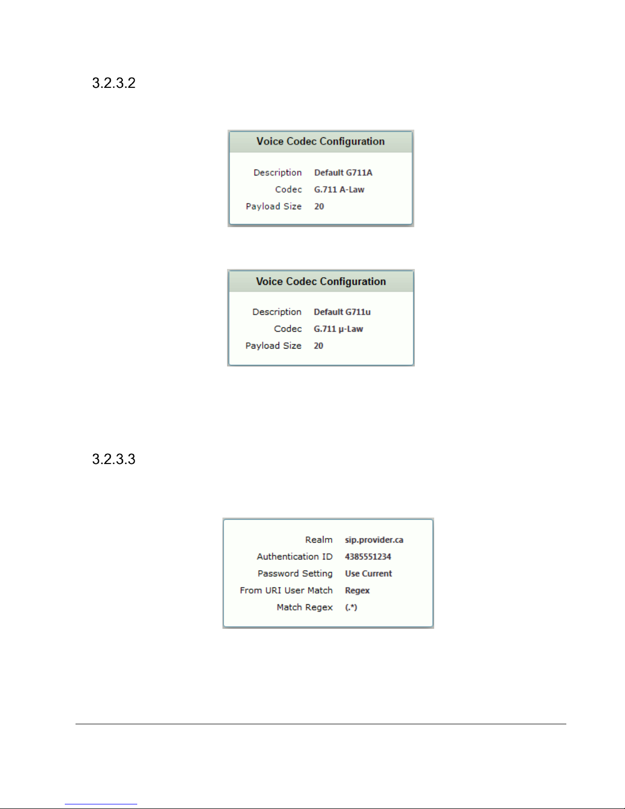
Voice Codec Profiles
Shown below are voice codec profiles used for the SBC 1000 in the test.
Figure 7: Voice codec configuration Default G711A
Figure 8: Voice codec configuration Default G711u
SIP Remote Authorization Table
SIP Remote Authorization Tables contain the credentials required to answer SIP Challenges to
Requests sent to ThinkTel. The information to complete this table is provided from ThinkTel.
Figure 9: SIP Remote Authorization Table
Sonus – Network Design Group 12 of 35
Copyright © 2015, Sonus and/or its affiliates. All rights reserved.
Page 13
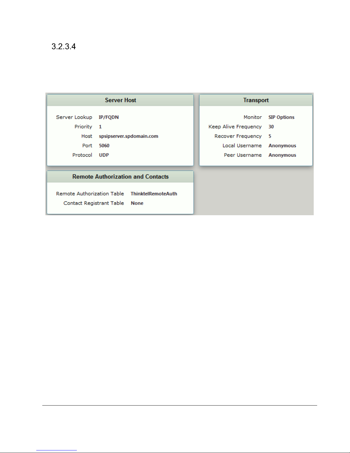
SIP Server Tables
SIP Server Tables contain information about the SIP devices connected to the Sonus SBC 1000/2000.
The entries in the tables provide information about the IP addresses, ports, and protocols used to
communicate with each server. The table entries also contain links to counters that are useful for
troubleshooting.
Figure 10: SIP Server Table
Sonus – Network Design Group 13 of 35
Copyright © 2015, Sonus and/or its affiliates. All rights reserved.
Page 14
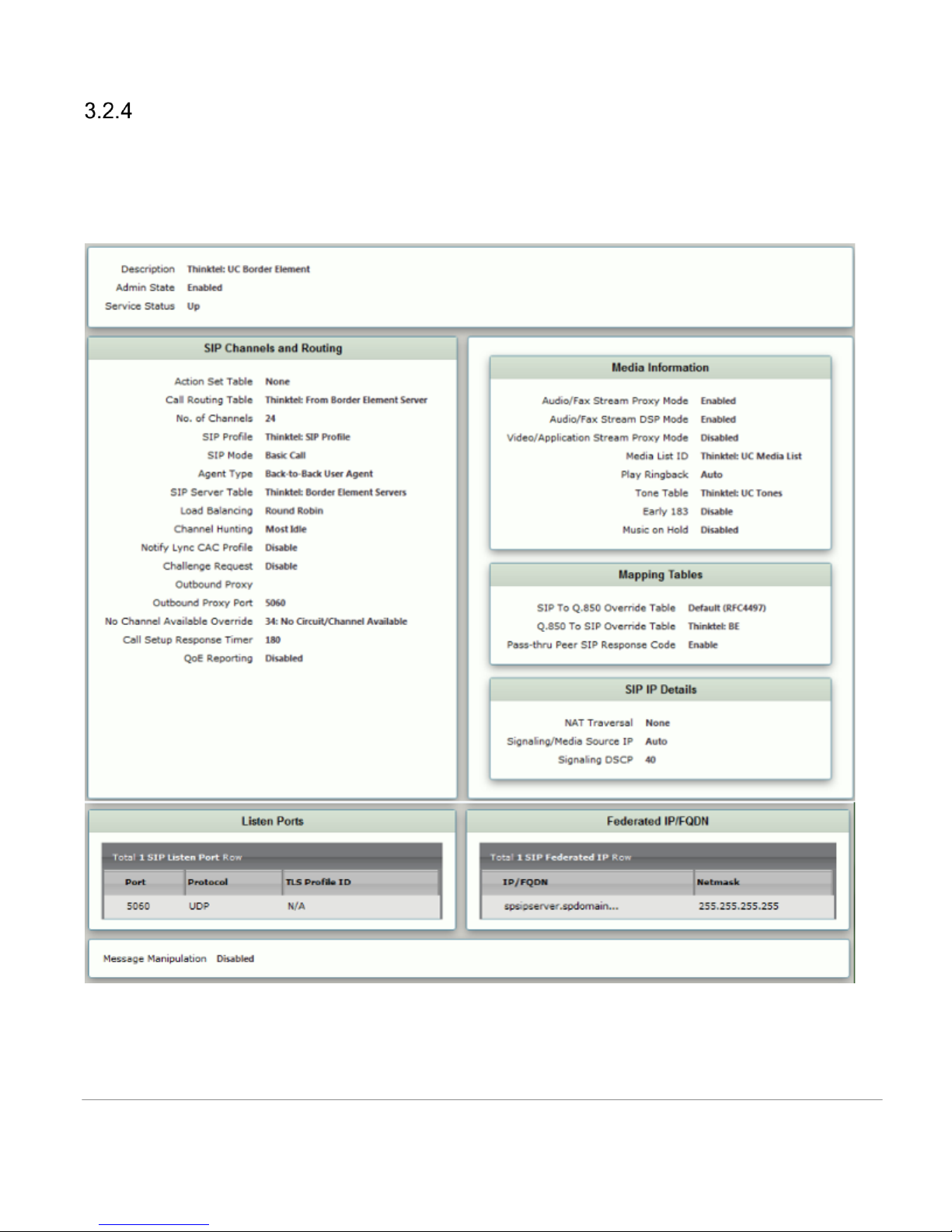
Signaling Groups
Signaling Groups allow telephony channels to be grouped together for the purposes of routing and shared
configuration. Calls are routed to Signaling Groups, as well as the location from which Call Routes are selected.
Signaling Groups provide the location from which Tone Tables and Action Sets are selected. In the case of SIP,
Signaling Groups specify protocol settings and link to server, media, and mapping tables.
Figure 11: SIP Signaling Group to ThinkTel
Sonus – Network Design Group
Page 15
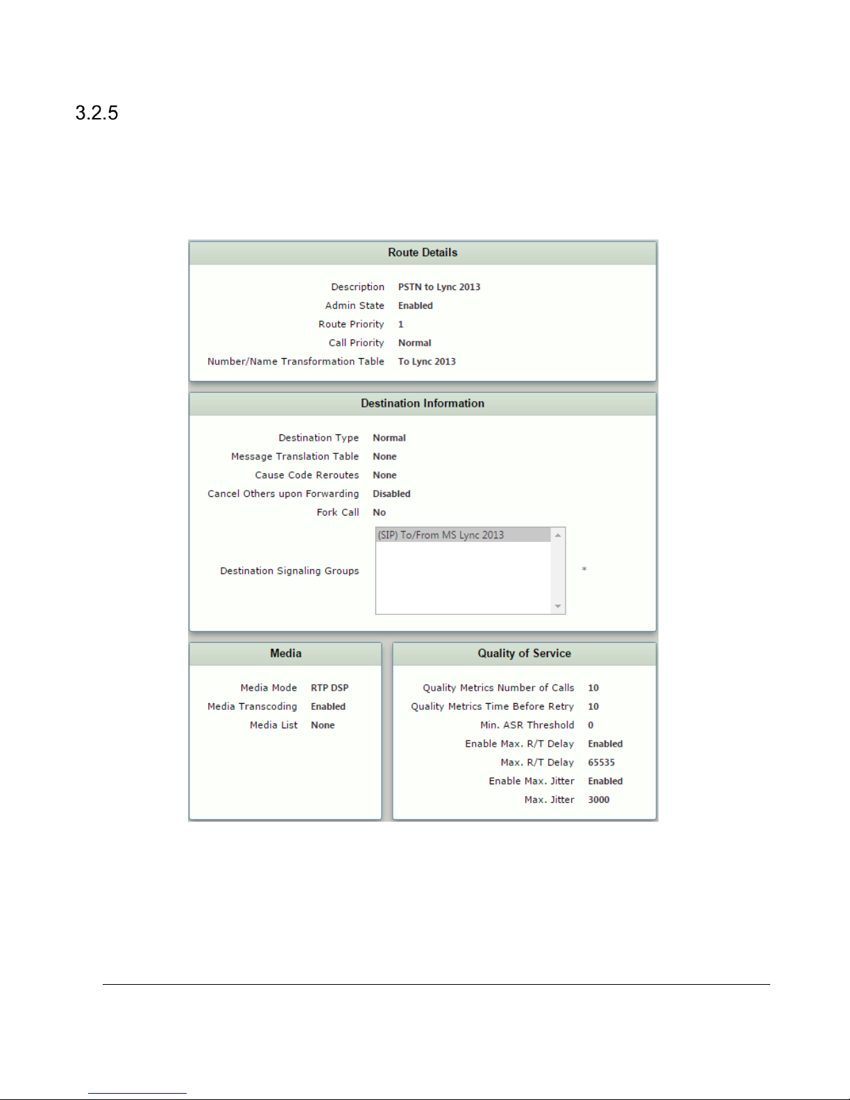
Call Routing Table
Call Routing allows calls to be carried between Signaling Groups, which permits calls to be carried between
ports and between protocols (for example, ISDN to SIP). Routes are defined by Call Routing Tables and allow
for flexible configurations that determine how calls are carried and translated. Call Routing Tables are one of the
central connection points of the system linking Transformation Tables, message translations, Cause Code
Reroute, Tables, Media Lists, and the three types of Signaling Groups (ISDN, SIP and CAS).
Figure 12: Call Routing Table PSTN to Lync 2013
Sonus – Network Design Group 15 of 35
Copyright © 2015, Sonus and/or its affiliates. All rights reserved.
Page 16
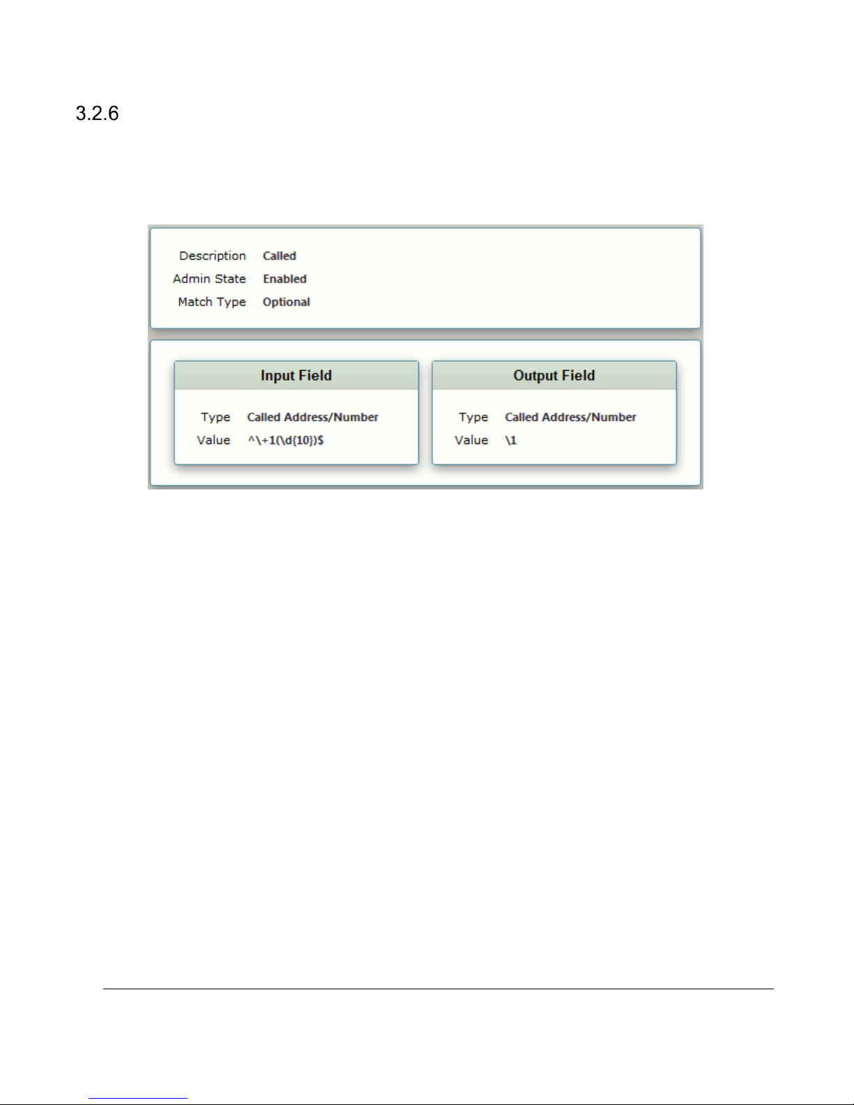
Transformation Tables
Transformation Tables facilitate the conversion of names, numbers, and other fields when routing a call. For
example, Transformation Tables convert a public PSTN number into a private extension number, or a SIP
address (URI). Every entry in a Call Routing Table requires a Transformation Table. In addition, Transformation
Tables are configurable as a reusable pool that Action Sets can reference.
Figure 13: Transformation Table Remove +1 From Lync
Sonus – Network Design Group 16 of 35
Copyright © 2015, Sonus and/or its affiliates. All rights reserved.
Page 17
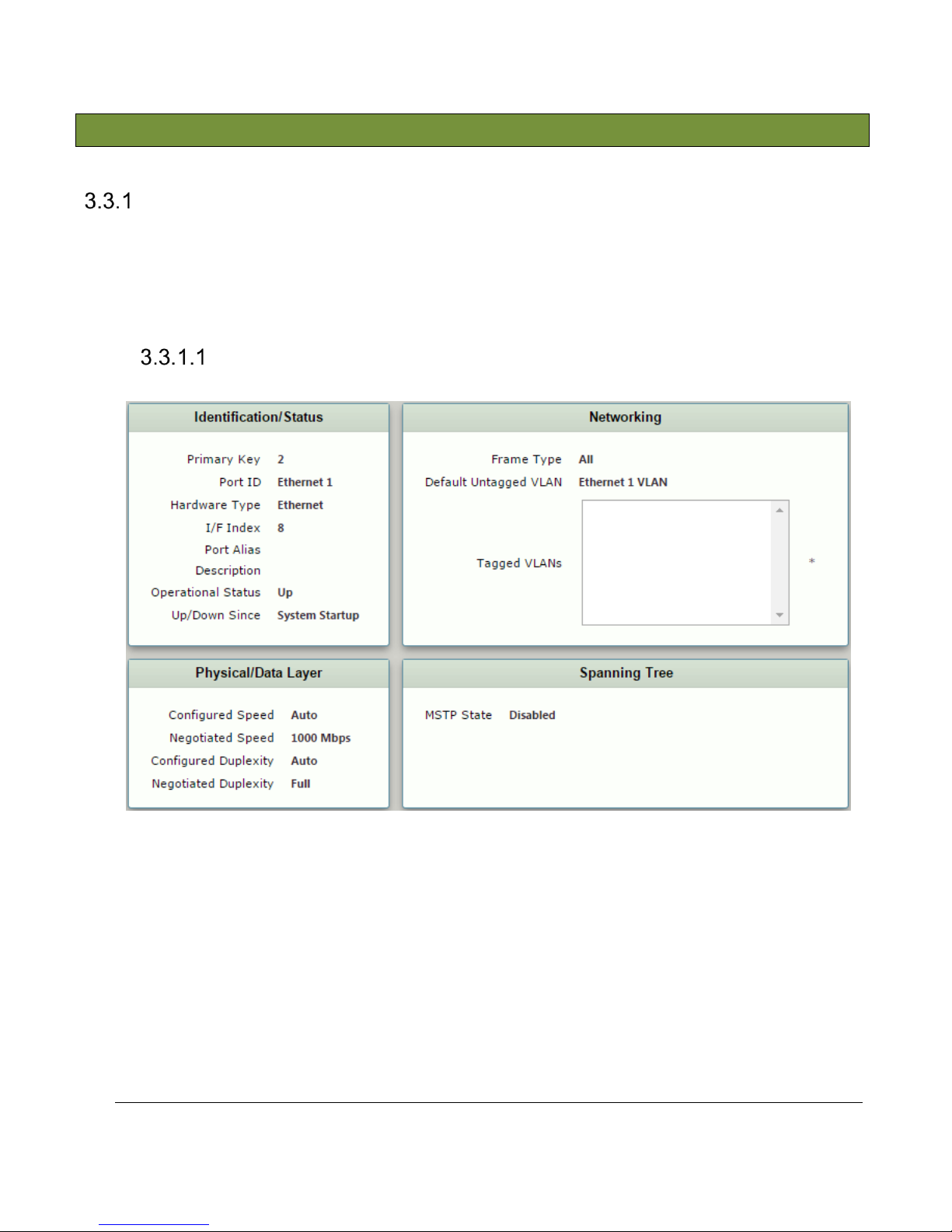
3.3 Internal Side SBC Configuration
Node Interfaces
The Sonus SBC 1000 allows you to configure the Identification information, Physical Data Layer, and Networking
Layer for the Ethernet ports. If you want to change the IP address, you must configure the associated Logical
Interface or use the Modify Ethernet IP task found under the Tasks tab.
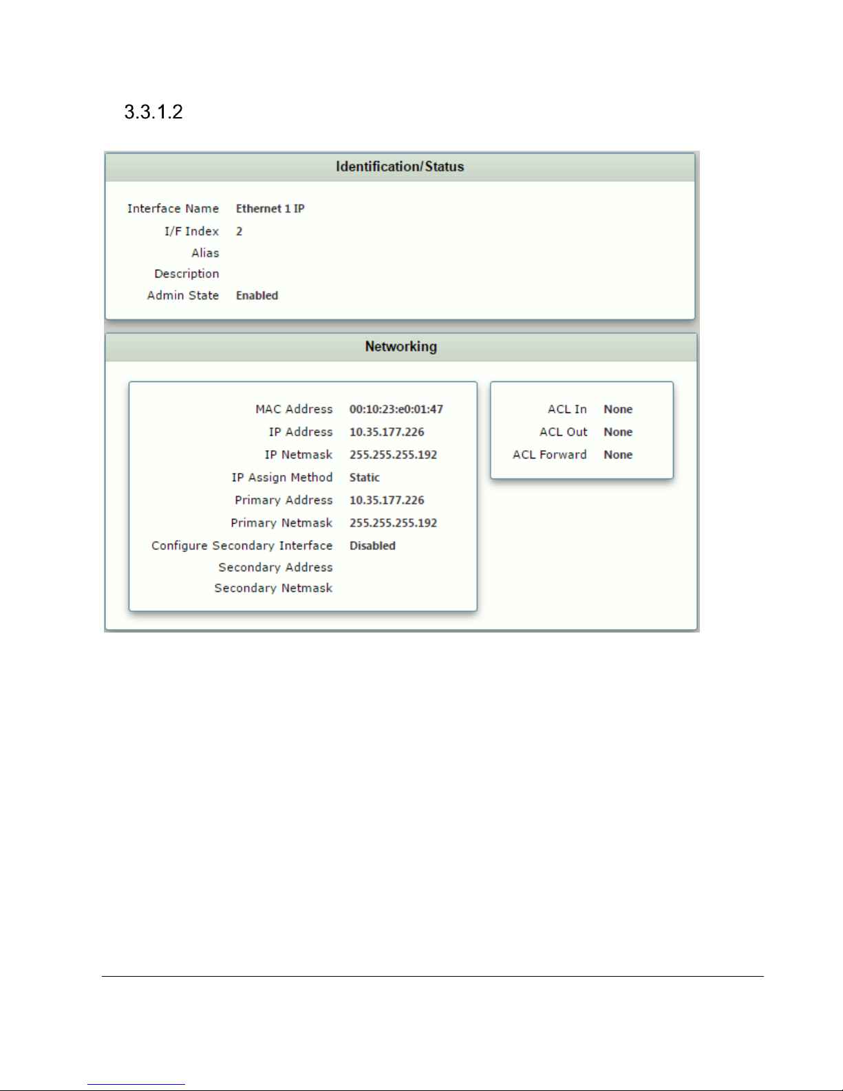
Shown below are the settings for the Ethernet connection between the Sonus SBC 1000 and Lync 2013.
Node Ports
Sonus – Network Design Group 17 of 35
Copyright © 2015, Sonus and/or its affiliates. All rights reserved.
Figure 14: Node Port
Page 18
Node Interfaces
Figure 15: Logical Interface
Sonus – Network Design Group 18 of 35
Copyright © 2015, Sonus and/or its affiliates. All rights reserved.
Page 19
SIP Profile
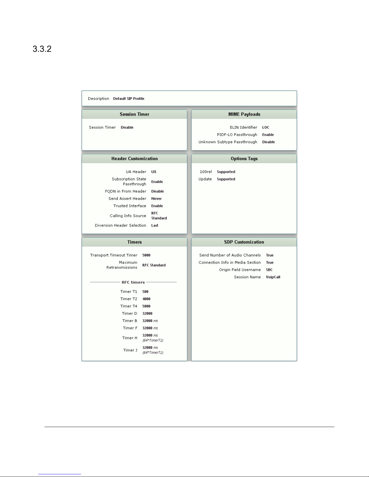
SIP Profiles control how the Sonus SBC 1000/2000 communicates with SIP devices and control important
characteristics such as: session timers, SIP header customization, SIP timers, MIME payloads, and option tags.
Shown below is the default SIP profile used for the SBC 1000 for this test.
Sonus – Network Design Group 19 of 35
Copyright © 2015, Sonus and/or its affiliates. All rights reserved.
Figure 16: SIP profile
Page 20
Media Profiles
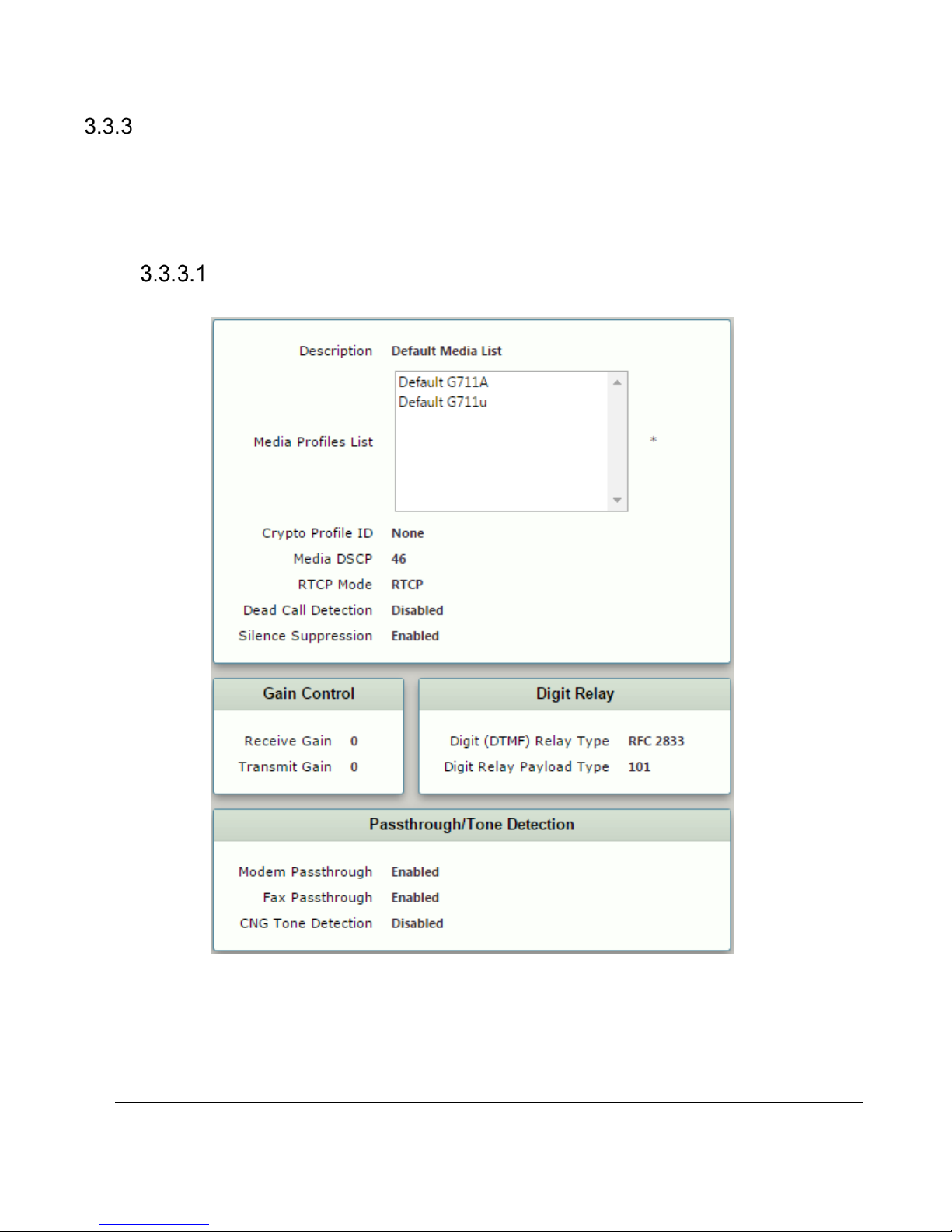
Media Profiles allow you to specify individual voice and fax compression codecs and their associated settings,
for inclusion in a Media List. Different codecs provide varying levels of compression allowing you to reduce
bandwidth requirements at the expense of voice quality. For reference, the Media Profile used for the SBC 1000
is shown below.
Media Lists
Shown below is the Media List configuration for the SBC 1000 in this test.
Sonus – Network Design Group 20 of 35
Copyright © 2015, Sonus and/or its affiliates. All rights reserved.
Figure 17: Media List
Page 21
Voice Codec Profiles
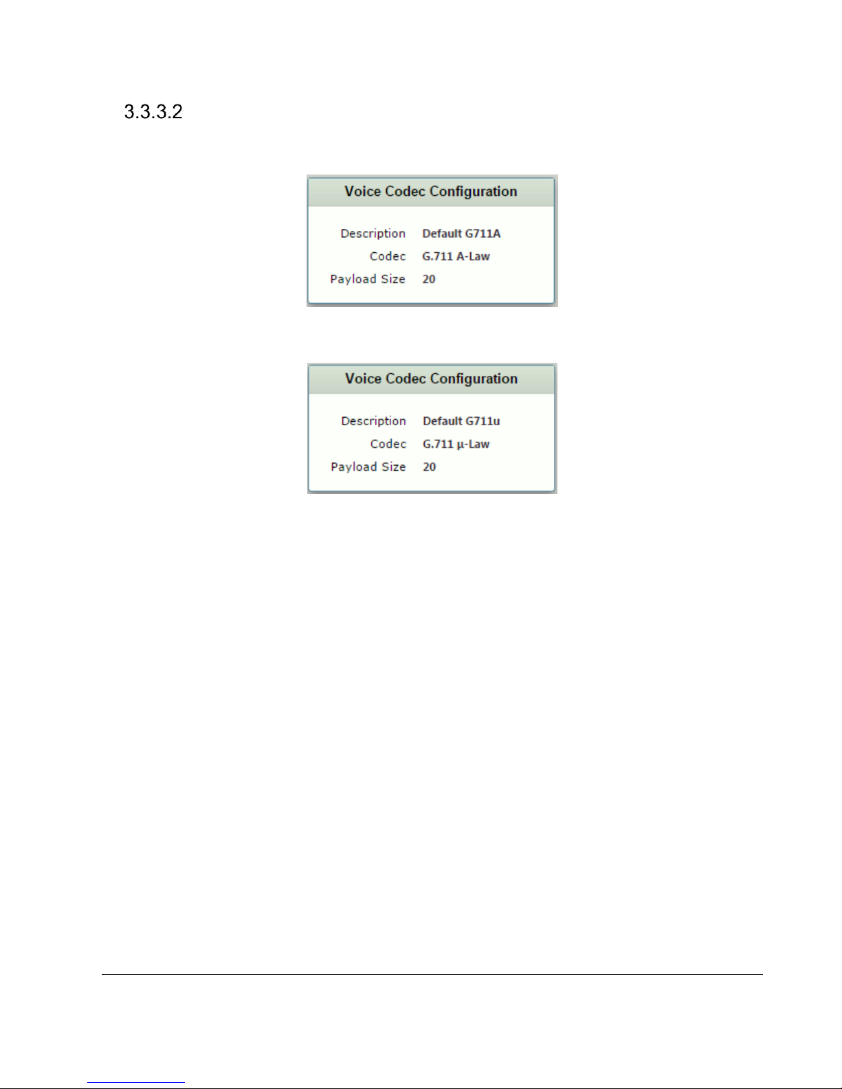
Shown below are the default voice codec profiles used for the SBC 1000 in this test.
Figure 18: Voice codec configuration Default G711A
Figure 19: Voice codec configuration Default G711u
Sonus – Network Design Group 21 of 35
Copyright © 2015, Sonus and/or its affiliates. All rights reserved.
Page 22
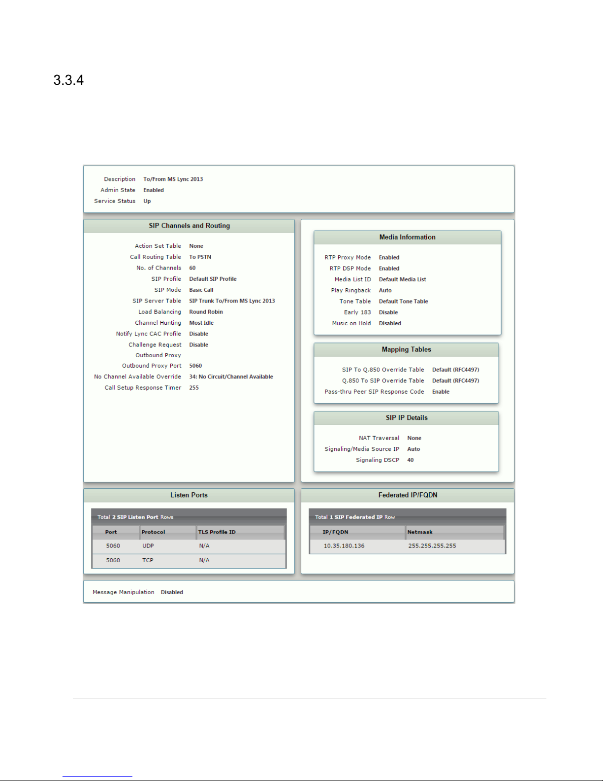
Signaling Group
Signaling Groups allow telephony channels to be grouped together for the purpose of routing and shared
configuration. Calls are routedto Signaling Groups, which also provide the location from which Call Routes are
selected. Signaling Groups are the location from which Tone Tables and Action Sets are selected. In the case of
SIP, Signaling Groups specify protocol settings and link to server, media, and mapping tables.
Sonus – Network Design Group 22 of 35
Copyright © 2015, Sonus and/or its affiliates. All rights reserved.
Figure 20: Signaling Group
Page 23
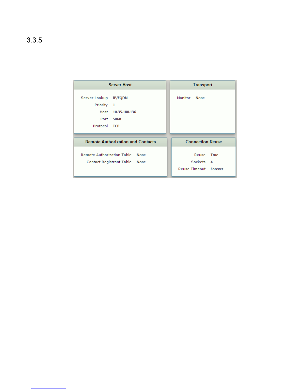
Sip Server Table
SIP Server Tables contain information about the SIP devices connected to the Sonus SBC 1000/2000. SIP
Server Tables emulate a traditional ‘SIP trunk group’ with table entries that provide information about the IP
addresses, ports, and protocols used to communicate with each server. The table entries also contain links to
counters that are useful for troubleshooting. An example of a SIP Server Table is shown below.
Figure 21: Sip Server Table
Sonus – Network Design Group 23 of 35
Copyright © 2015, Sonus and/or its affiliates. All rights reserved.
Page 24
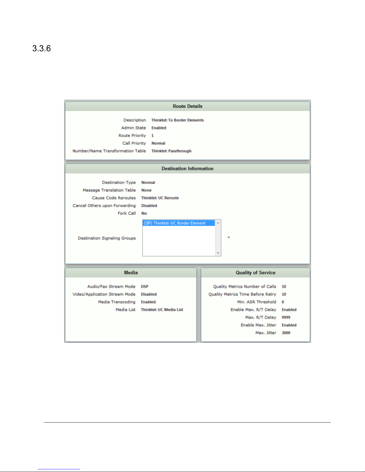
Call Routing Table
Call Routing allows calls to be carried between Signaling Groups, which permit calls to be carried between ports,
and between protocols (for example, ISDN to SIP). Routes are defined by Call Routing Tables that provide
flexible configurations to determine how calls are carried and translated. Call Routing Tables are one of the
central connection points of the system linking Transformation Tables, Message Translations, Cause Code
Reroute, Tables, Media Lists, and the three types of Signaling Groups (ISDN, SIP and CAS).
Figure 22: SIP Call Routing Table To PSTN
Sonus – Network Design Group 24 of 35
Copyright © 2015, Sonus and/or its affiliates. All rights reserved.
Page 25
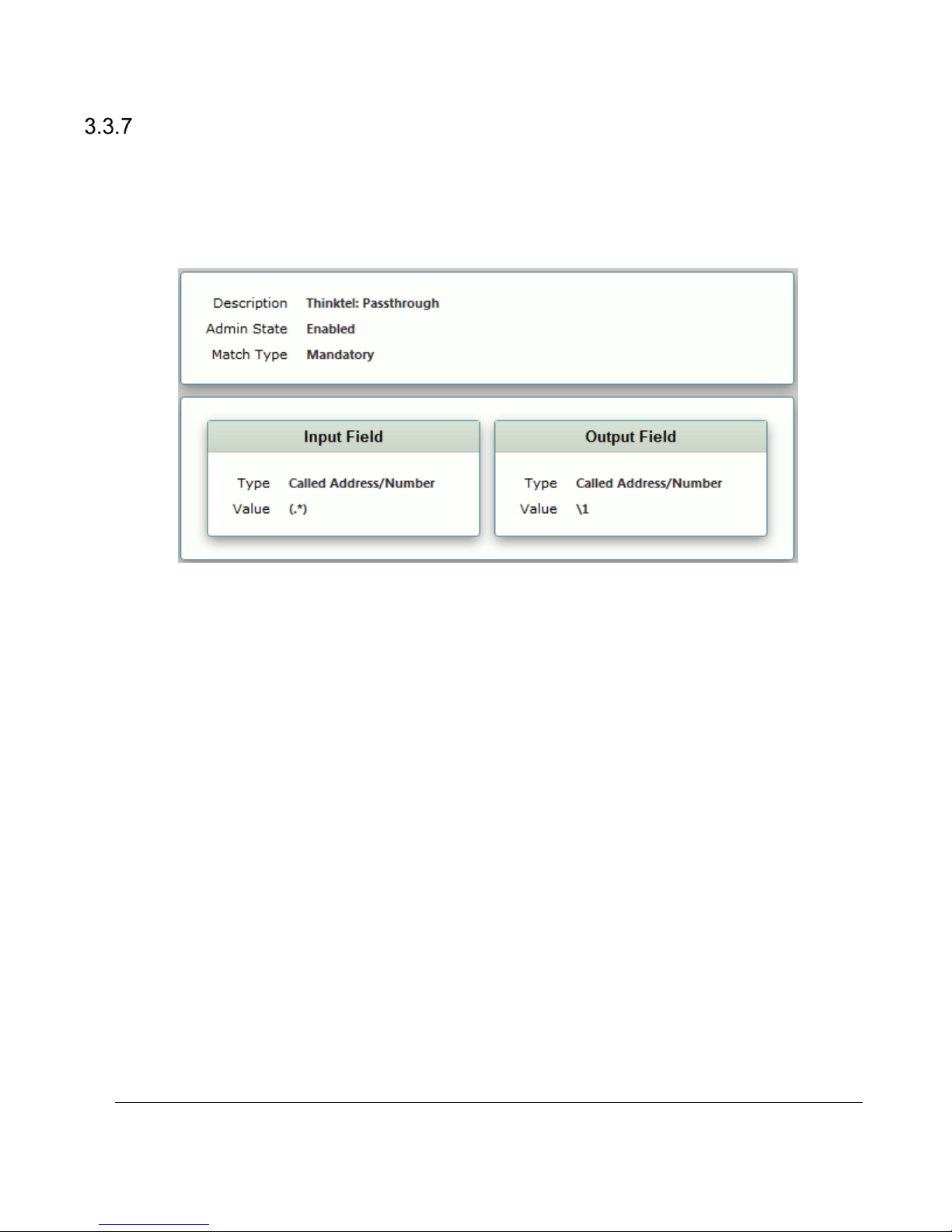
Transformation Tables
Transformation Tables facilitate the conversion of names, numbers, and other fields when routing a call. For
example, Transformation Tables can convert a public PSTN number into a private extension numberor a SIP
address (URI). Every entry in a Call Routing Table requires a Transformation Table, and serves as the location
where the entry is selected. In addition, Transformation Tables are configurable as a reusable pool that Action
Sets can reference.
Figure 23: Transformation Table Match ThinkTel
Sonus – Network Design Group 25 of 35
Copyright © 2015, Sonus and/or its affiliates. All rights reserved.
Page 26
4 Lync Server 2013 Configuration
This section assumes the Lync Server components are installed with Lync users. The user should be familiar
with Lync Server Topology Builder, Lync Server Control Panel, and Lync Server Management Shell. This section
does not cover the basic installation of Lync Server 2013.
4.1 Lync 2013 Configuration Settings
Adding the SBC to the Lync Server.
The Lync Server topology must be modified by adding the SBC as a Gateway device. The Gateway device
functions as the interface to the Verizon SIP Trunk. The following instructions describe how to add the SBC to
the Lync Server topology.
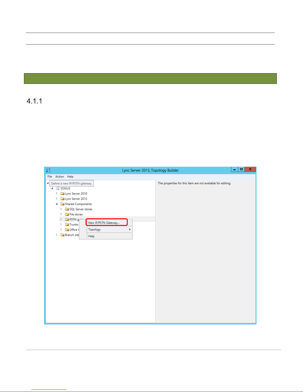
1. Open the Lync Server Topology Builder and load the current topology.
2. Expand the topology and right click on the PSTN Gateways link in the left hand pane.
3. Select New IP/PSTN Gateway… from the pop-up menu as shown below, and then follow the steps to
complete the process.
Sonus – Network Design Group
Figure 24: Create New Gateway
Page 27
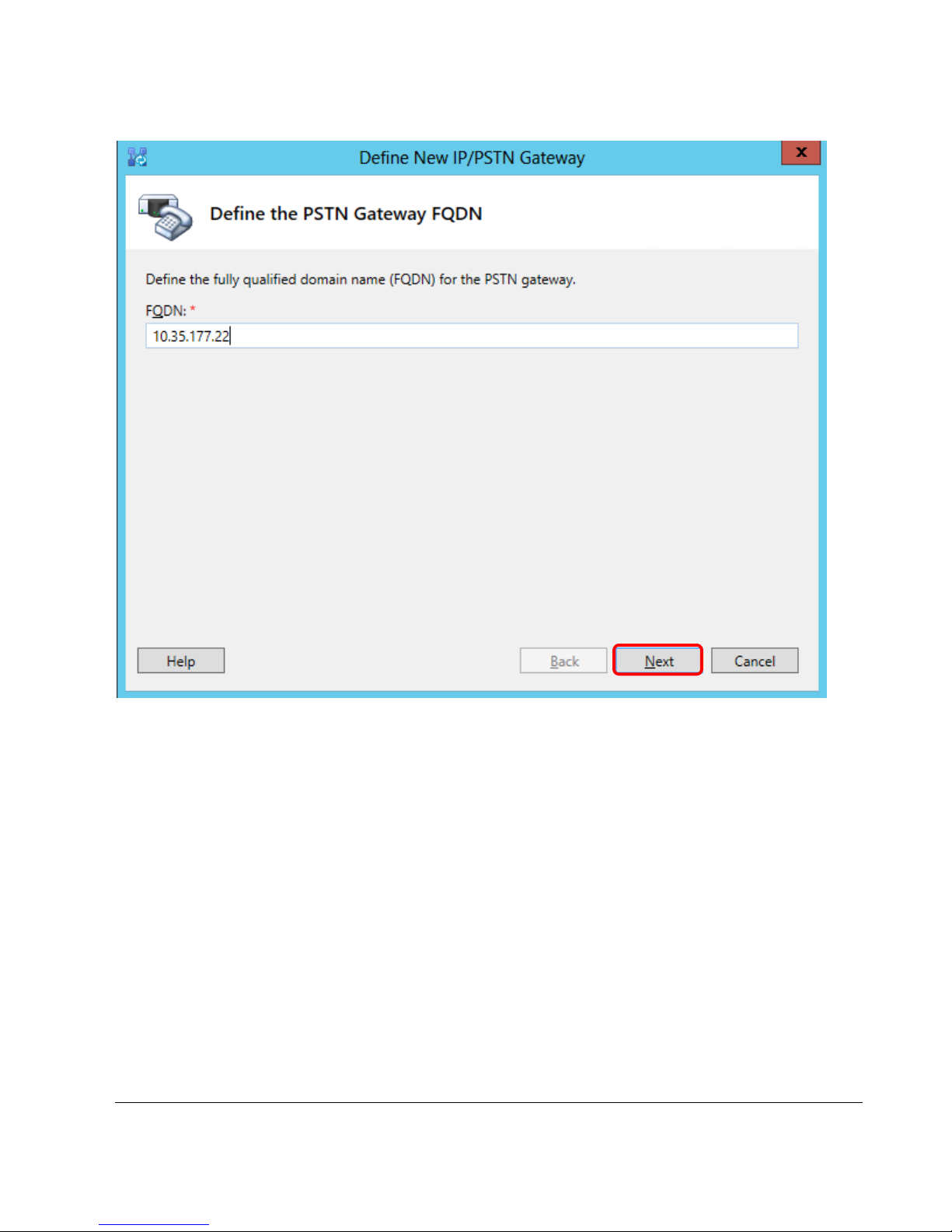
Figure 25: Define the FQDN of the Gateway
Sonus – Network Design Group 27 of 35
Copyright © 2015, Sonus and/or its affiliates. All rights reserved.
Page 28
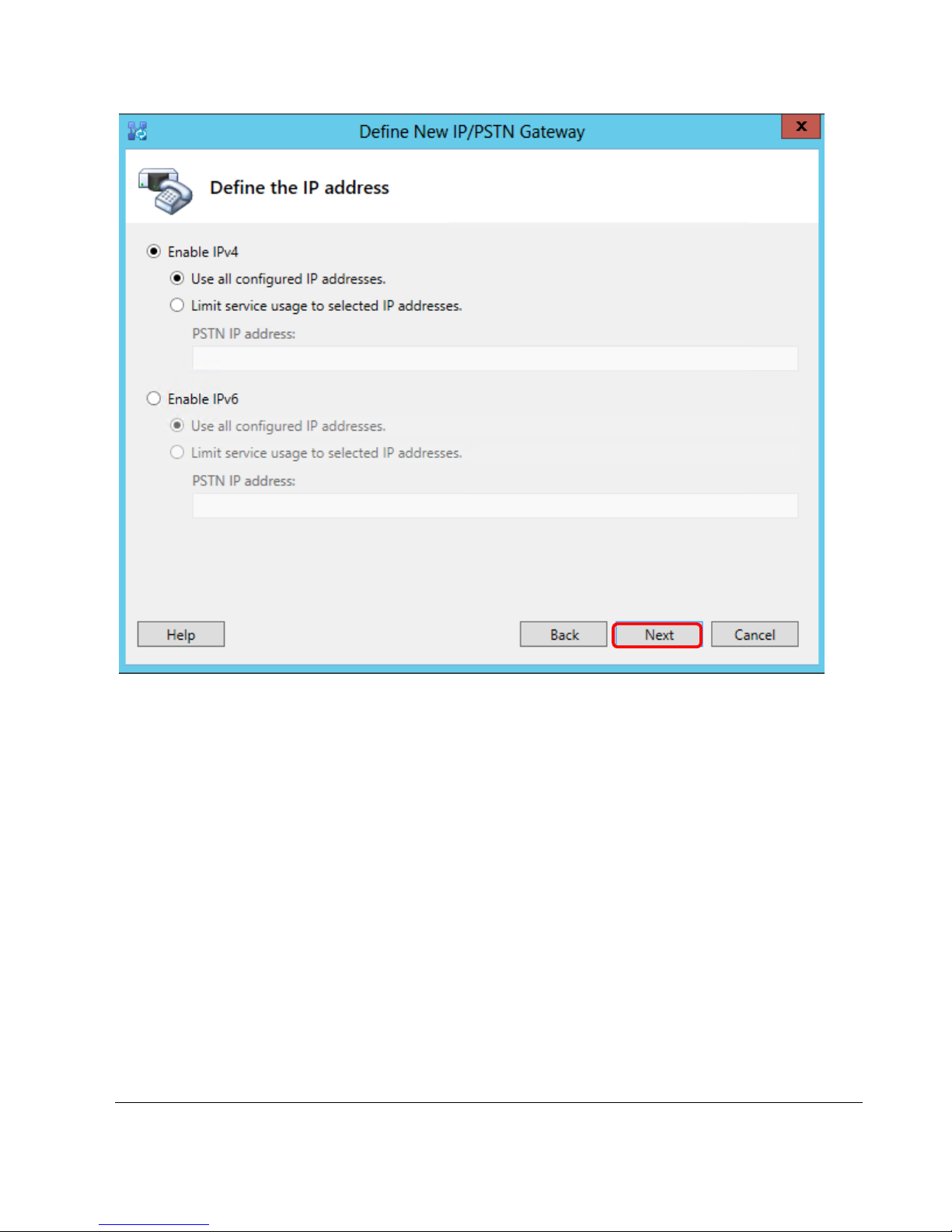
Figure 26: Enable IPV4/IPV6
Sonus – Network Design Group 28 of 35
Copyright © 2015, Sonus and/or its affiliates. All rights reserved.
Page 29
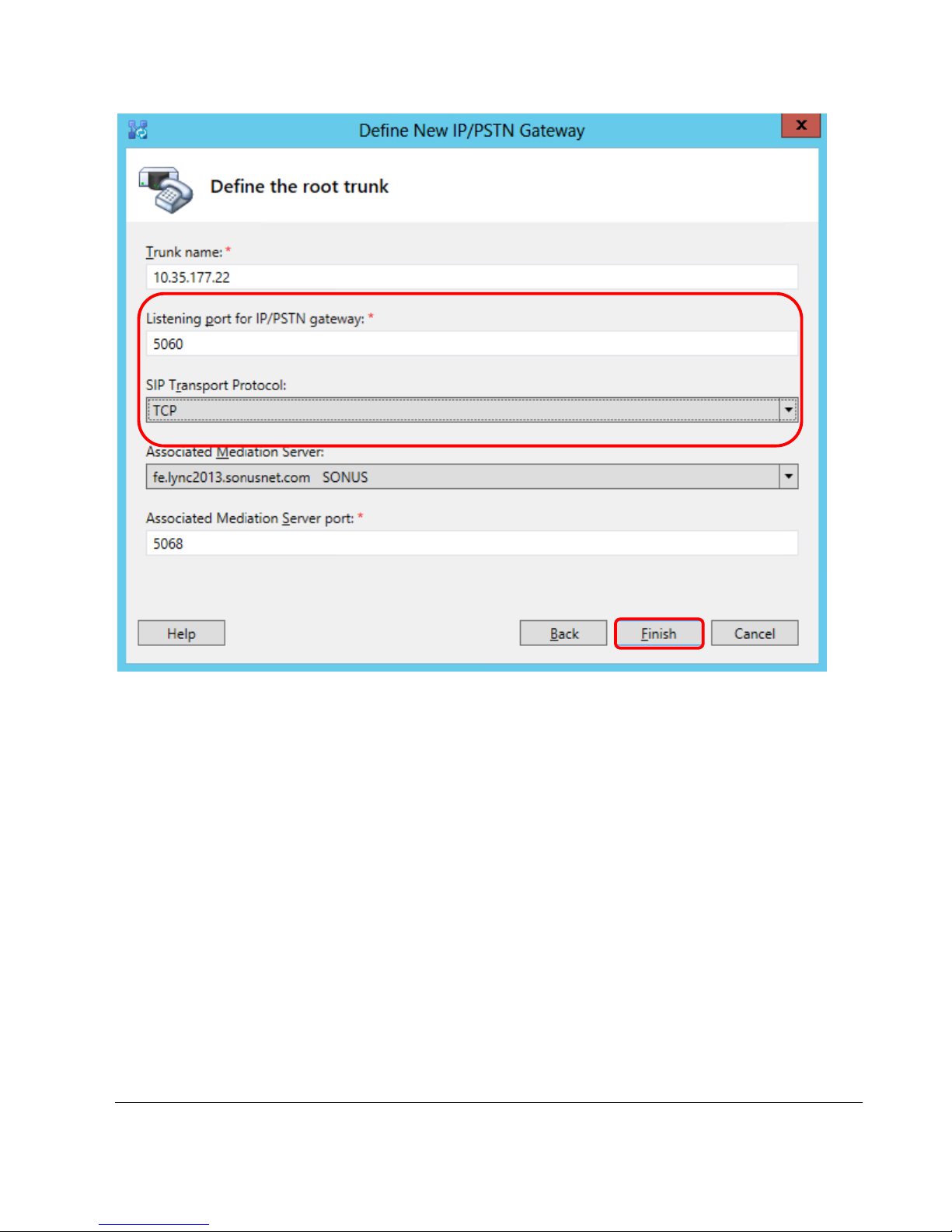
Figure 27: Define Trunk Port and Protocol
Sonus – Network Design Group 29 of 35
Copyright © 2015, Sonus and/or its affiliates. All rights reserved.
Page 30
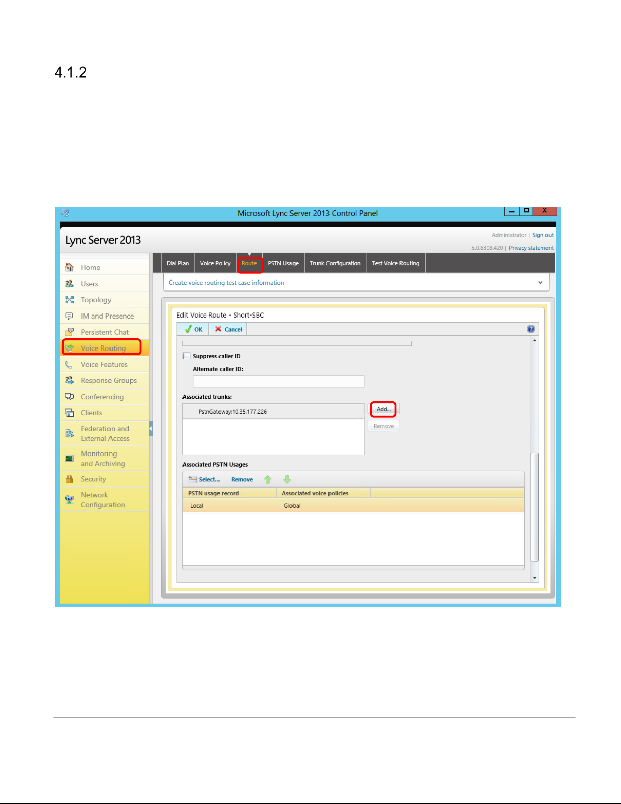
Adding the SBC to the Lync Server 2013 Routing.
Before Lync Server 2013 can send calls to the Verizon SIP Trunk, the SBC will have to be added to the
Lync Server Routing. The following instructions describe how to add the SBC to the Lync Server Routing
configuration.
1. Open the Lync Server Control Panel and click on the Voice Routing link in the left hand pane.
2. Click on the Route tab on top of the right hand pane and scroll down to the screen dialog as shown
below.
Sonus – Network Design Group
Figure 28: Add Routing
Page 31
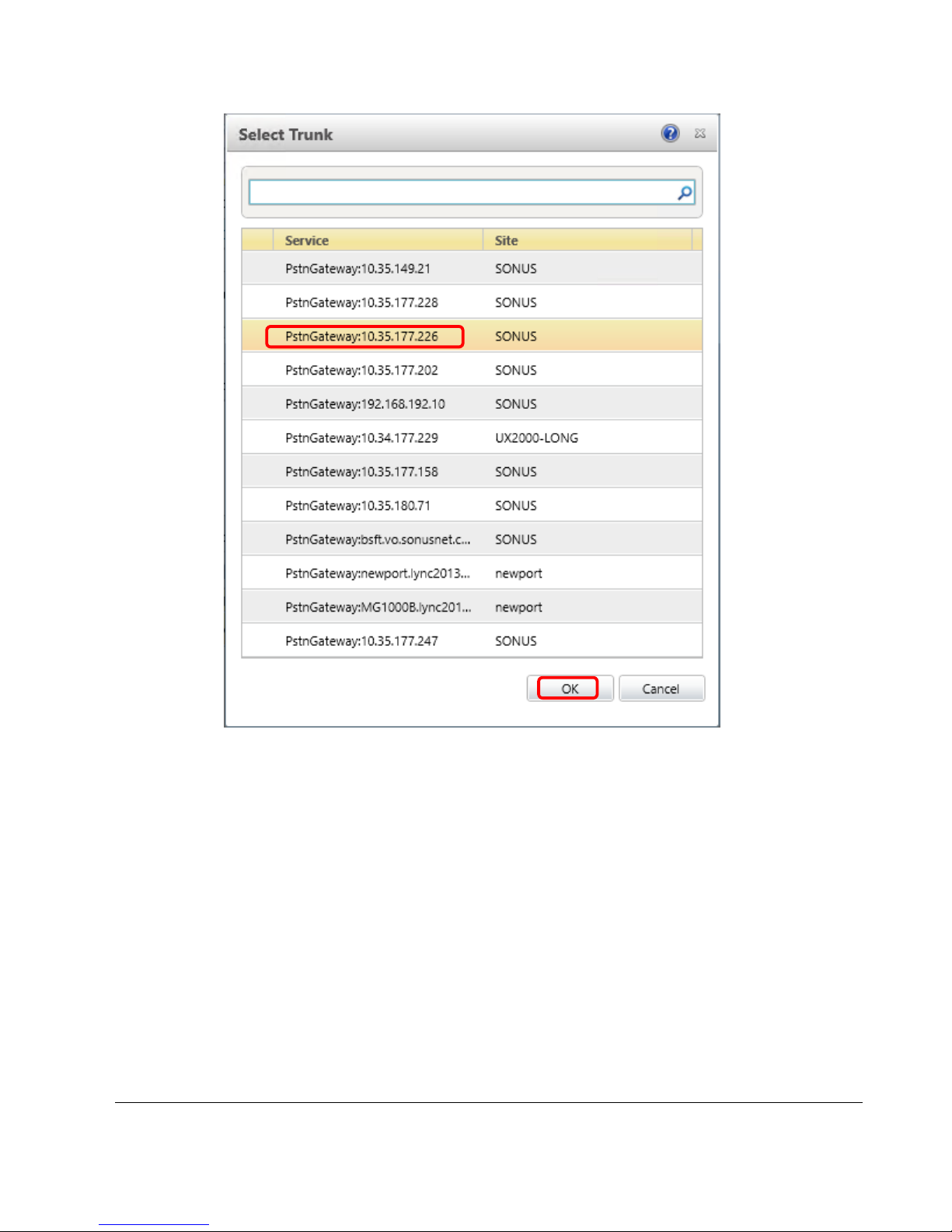
Figure 29: Select Trunk
Ensure the desired SBC is highlighted in the trunk listing, as shown above, and click OK. Commit these
changes to the topology.
Sonus – Network Design Group 31 of 35
Copyright © 2015, Sonus and/or its affiliates. All rights reserved.
Page 32
5 SBC and Lync 2013 Specific Configurations
The type of call scenario required determines the configuration settings for the SBC and Microsoft Lync 2013
product.
5.1 Initial Setup for All Calls
Calling number manipulation
Transformation Tables are required for the purpose of mapping pre-configured Lync 2013 user extensions to
established ThinkTel SIP Trunk DIDs. This is not expected to be a requirement for deployment scenarios.
Called number
Normal calling pattern used for testing is to dial all digits in E.164 format for both national and international calls.
Other dialing patterns tested include Emergency calls.
Sonus – Network Design Group 32 of 35
Copyright © 2015, Sonus and/or its affiliates. All rights reserved.
Page 33
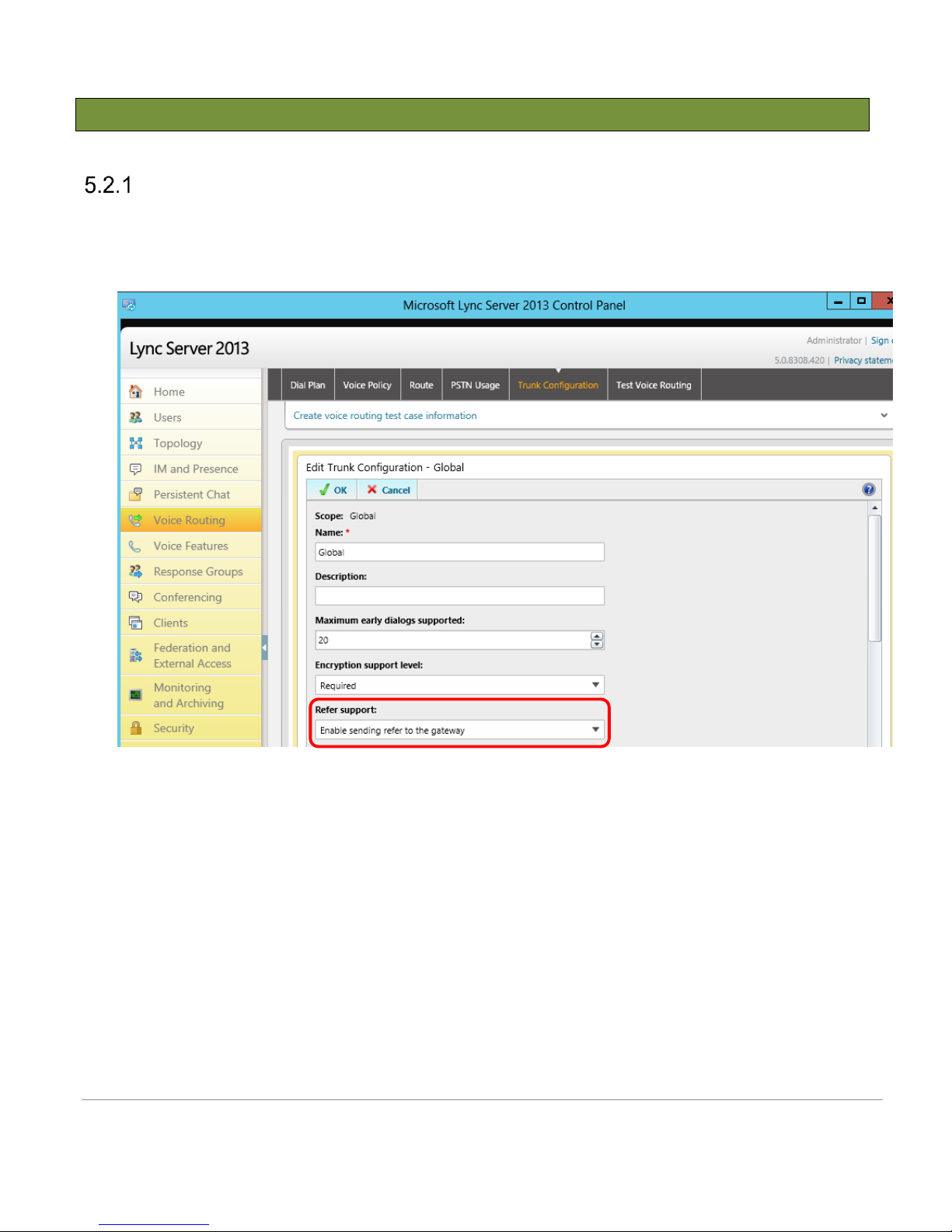
5.2 Initiating Transfers with REFER
Call transfer using SIP REFER Method
Microsoft Lync Server 2013 requires additional configuration in order to enable SIP REFER Method. Under
Trunk Configuration profile (that is assigned to the desired SBC trunk), REFER support must be set to ‘Enable
sending refer to the gateway’ .
Figure 30: Sip Server Table
Sonus – Network Design Group
Page 34
5.3 Initiating Transfers with Re-INVITE
Call transfer using Re-Invite method
Transferring a call to another phone number is supported with the RFC3261 method. No special flag is required
to be set for this method. Ensure that REFER support is set to “none” on Lync 2013, under the “Trunk
Configuration” object.,
5.4 Call Hold
Call Hold using RFC3264
Placing a call on hold is performed with the RFC3264 method. This method is preferred for connections on
ThinkTel SIP Trunks. The RFC3264 method involves sending a Re-INVITE with the parameter: a = inactive. No
special flag is required to be set for this method.
5.5 Media System Configuration
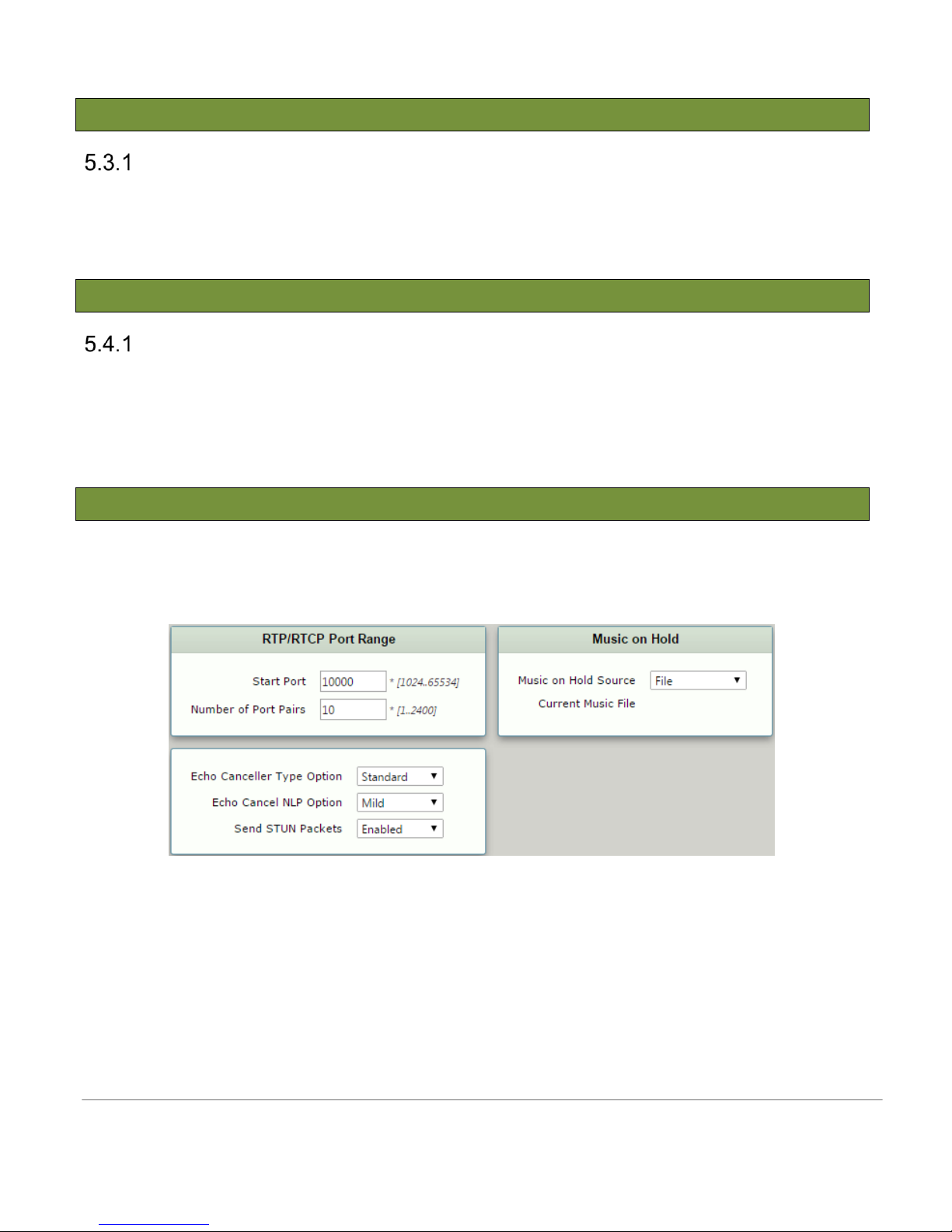
For testing, Media port range is set with a range from 10000-10020 for security purposes. This is not expected to
be a requirement for deployment scenarios
Figure 31: Media System Configuration
Sonus – Network Design Group
Page 35
6 Exceptions
6.1 Lync 2013 Exceptions
302 Moved Temporarily
Lync 2013 Server will not send 302 Moved Temporarily towards the SBC, hence this method is not supported
according to the Microsoft Lync Interop Specification.
6.2 SBC1000 Exceptions
Fax V.34
Fax V.34 transmission is not supported over T.38v0.
Sonus – Network Design Group 35 of 35
Copyright © 2015, Sonus and/or its affiliates. All rights reserved.
 Loading...