

Page 1

Einbau- und Betriebsanleitung statischer Wärmezähler Superstatic 449
Installation guidelines Static Heat Meter Superstatic 449
Allgemeines
Der statische Durchflusssensor und das Rechenwerk dürfen nur innerhalb
der auf dem Typenschild sowie in der technischen Spezifikation
aufgeführten Bedingungen betrieben werden! Bei Missachtung dieser
Vorgaben ist eine Haftung des Herstellers ausgeschlossen. Der Hersteller
haftet nicht für unsachgemäßen Einbau und Betrieb.
Plomben dürfen nicht bzw. nur durch autorisierte Personen entfernt werden,
dabei sind länderspezifische und lokale Vorschriften sowie die
Herstellerangaben zu beachten! Der Hersteller übernimmt keine
Verantwortung für die Änderung der eich- und messrelevanten Daten, falls
die werkseitige Verplombung aufgebrochen oder verletzt worden ist.
Bei der Verwendung von mehreren Wärmezählern in einer AbrechnungsEinheit sollten im Interesse einer möglichst gerechten WärmeverbrauchsMessung gleiche Gerätearten und Einbaulagen gewählt werden.
Vor der Montage
- Auslegungsdaten der Anlagen überprüfen.
- Die Impulswertigkeit und der Einbauort des Durchflusssensors müssen
mit den auf dem Rechenwerk angegebenen Werten übereinstimmen,
Typenschilder beachten!
- Die zulässige Umgebungstemperatur beim Rechenwerk beträgt 5...55°C.
- Die Installations- und Projektierungsvorschriften sind zu beachten.
- Die Ablesbarkeit des Rechenwerkes und sämtlicher Typenschilder ist zu
beachten.
Hinweise zur richtigen Zählermontage:
Bedingungen zur Einhaltung der Richtlinie
2004/22/EG (MID) und der korrekten Einbaulagen siehe Seite 12
- Das Rechenwerk ist standardmäßig für den Einbau im Rücklauf
parametriert. Für den Einbau im Vorlauf ist eine spezielle Parametrierung
erforderlich, welche bei der Bestellung angegeben werden muss.
- Das Kabel zwischen dem Durchflusssensor und dem Rechenwerk darf
nicht verlängert oder verkürzt werden werden! Das Kabel ist plombiert.
- Alle Leitungen müssen mit einem Mindestabstand von 300 mm zu
Starkstrom- und Hochfrequenzkabeln verlegt werden.
- Strahlungswärme und elektrische Störfelder in der Nähe des
Rechenwerkes sind zu vermeiden.
- Das Rechenwerk ist generell abgesetzt von der Kälteleitung zu montieren.
- Es ist darauf zu achten, dass kein Kondensatwasser entlang der angeschlossenen Leitungen ins Rechenwerk laufen kann.
- Sofern die Gefahr von Erschütterungen im Rohrleitungssystem besteht,
sollte das Rechenwerk getrennt an der Wand montiert werden.
- Der Durchflusssensor sollte zwischen zwei Absperrventilen montiert
werden.
- Bei der Montage des Durchflusssensors muss der Messkopf seitlich
liegen (siehe Seite 12).
- Beim Durchflusssensor ist die Durchflussrichtung zu beachten (Pfeil auf
dem Durchflusssensor).
- Die Rohrleitung ist vor der Montage des Durchflusssensors zu spülen, um
zu gewährleisten, dass sich keine Fremdkörper in der Leitung befinden.
- Der Durchflusssensor soll VOR möglichen Regel-Ventilen montiert
werden um mögliche Störeinflüsse auszuschließen.
- Die Leitungen sind bei der Inbetriebnahme generell zu entlüften. Luft im
System oder im Durchflusssensor kann das Messergebnis beeinträchtigen.
- Verwenden Sie nur geeignetes, neues Dichtungsmaterial.
- Die Dichtigkeit der verschiedenen Anschlüsse muss überprüft werden.
- Ein Blitzschutz kann nicht gewährleistet werden; dies ist über die Hausinstallation sicherzustellen.
Beim statischen Wärmezähler Superstatic handelt es sich um ein Kompaktgerät. Es besteht aus den folgenden drei Teilgeräten:
- Schwingstrahl Durchflusssensor
- Rechenwerk Supercal
- Temperaturfühler (2- oder 4-Leitertechnik) mit oder ohne Tauchhülsen
Die Impulswertigkeit des Rechenwerks und des Durchflusssensors
sowie der Widerstand der Temperaturfühler und Rechenwerk müssen
aufeinander abgestimmt sein. Etiketten der Geräte vergleichen!
General
The static flow sensor and the integrator may only be operated within the
conditions outlined on the identification plate, as well as within the technical
specification! In case of ignoring these default conditions, the manufacturer’s
responsibility is void.
The manufacturer is not liable for inappropriate installation and operation.
Seals may not be removed and/or only by authorized persons. The countryspecific, local regulations, as well as the manufacturer instructions must be
respected!
If the manufacturer’s seal has been broken or damaged, the manufacturer
cannot be made responsible for the change of the verified and measuring
relevant data.
When using several heat meters in an installation unit, one should select, in
the interest of a at most possible fair heat consumption measurement, the
same types of device and installation positions.
Before installation
- Check the design layout data of the installation.
- The pulse value and the installation location of the flow sensor must
match the values indicated on the integrator, consult the identification
plate!
- The permissible ambient temperature range of the integrator is 5 - 55 ºC.
- The installation and project prescriptions must be followed.
- The readability of the integrator and also the identification plates must be
followed.
Remarks on the correct meter installation:
Conditions to comply with the directive
2004/22/EU (MID) and correct mounting positions see page 12
- The integrator is by default parameterized for installation into the return
flow. Special parameterization is necessary for installation in the supply
flow and this must be specified with the order.
- The cable between the flow sensor and the integrator must not be extended or shorted. The cable is be sealed.
- All wiring must be installed with a minimum distance of 300 mm from
heavy voltage and high frequency cables.
- Radiated heat and interfering electrical fields close to the integrator must
be avoided.
- In general, the integrator should be installed away from the cooling pipes.
- It has to be ensured that no condensed water can run along the wires into
the calculator.
- If the danger of vibrations in the piping system exists, the integrator should
be installed separately on the wall.
- The flow sensor should be installed between two shut-off valves.
- The flow sensor must be mounted with the measuring head to the side
(see page 12).
- The flow direction of the flow sensor must be respected (arrow on the flow
sensor).
- Flush the pipe system before installing the flow sensors to guarantee that
no foreign particles remain in the pipe.
- The flow sensor shall be mounted BEFORE any control valve to
exclude any potential parasitic influences.
- During commissioning the pipe system must be purged. Air in the system
of the flow sensor may affect the measurement..
- Use only new and appropriate sealing material.
- Water tightness of the different connections should be verified.
- A lightning protection cannot be ensured; this protection has to be guaranteed by the house installation.
The static heat meter Superstatic is a compact unit and consists of the following three partial units:
- Fluid oscillator of flow sensor
- Integrator
- Temperature sensors (2- or 4-wire) with or without pockets
The pulse values of the integrator and of the flow unit, as well as the
resistance value of the temperature sensors and the integrator are
matched one to the other. Compare the labels of the Devices!
0449P300 Installation Superstatic 449 DE EN 19-01-2012 1 Sontex SA, 2605 Sonceboz, Schweiz, Switzerland
Page 2
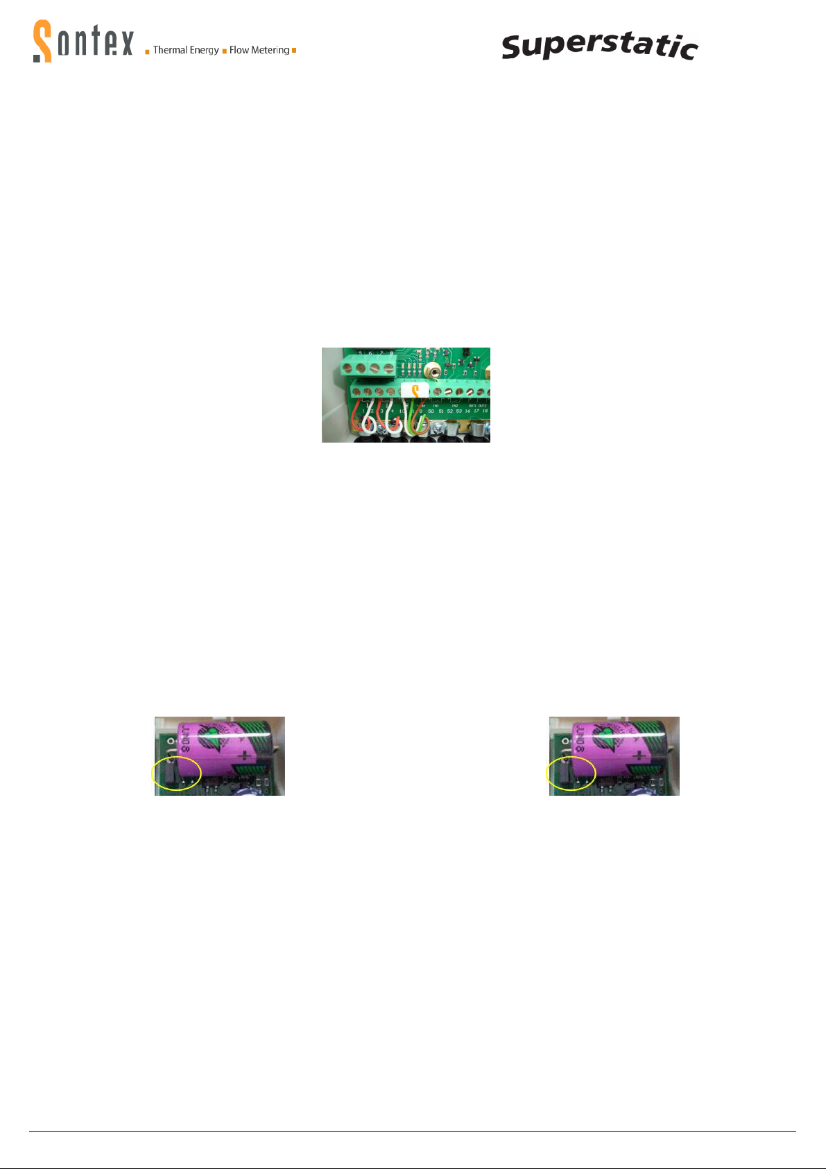
Kabelanschlüsse
Cable connection
Zum Anschluss der Ein- und Ausgänge ist das Oberteil des Rechenwerks zu
entfernen. Die Anschlüsse sind wie folgt vorzunehmen:
Klemme Anschlussart
1,2 Direktanschluss 2-Leitertechnik, Temperatur hoch
1,2 und 5,6 4-Leitertechnik, Temperatur hoch
3,4 Direktanschluss 2-Leitertechnik, Temperatur tief
3,4 und 7,8 4-Leitertechnik, Temperatur tief
10 (+) Impulseingang Durchflusssensor 449 (weisses Kabel)
11 (-) Impulseingang Durchflusssensor 449 (grünes Kabel)
9 Spannungsversorgung Durchflusssensor 449 (braunes
Kabel)
50 (+) Impulseingang zusätzlicher Impulseingang 1
51 (-) Impulseingang zusätzlicher Impulseingang 1
52 (+) Impulseingang zusätzlicher Impulseingang 2
53 (-) Impulseingang zusätzlicher Impulseingang 2
16 (+) Open collector-Ausgang 1
17 (-) Open collector-Ausgang 1 + 2
18 (+) Open collector-Ausgang 2
24 M-Bus (Optionales oder ab Werk bestücktes Modul)
25 M-Bus (Optionales oder ab Werk bestücktes Modul)
Klemmen 1 (5) und 2 (6) für Temperaturen hoch
Klemmen 3 (7) und 4 (8) für Temperaturen tief
Anschlussschema Temperaturfühler und
korrekte Einbaulagen s. Seite 4 und 12.
Achtung: Die geschirmten Kabel müssen generell mit
der Zugentlastung geerdet werden! (sehe Bild auf Seite 12)
Erdung
Es ist darauf zu achten, dass sämtliche Erdungsanschlusspunkte
(Leitungsnetz, externe Speisung und Chassis vom Durchflusssensor) der
Gesamtinstallation äquipotenzial sind.
Spannungsversorgungsmodule
Die Spannungsversorgungsmodule werden mittels einer Steckverbindung an
die Hauptanschlussplatine angeschlossen.
Netzmodule
Das Netzmodul 230V – 45/60 Hz ist mit einer 1A-Sicherung installationsseitig abzusichern. Die Netzmodule 230V AC, 24 VAC oder 12 – 24 VDC
sind mit einer Backupbatterie bestückt. Mit der Notstromversorgung über die
Backupbatterie arbeitet das Rechenwerk in einem batterie-schonenden
Modus. Die messtechnischen Eigenschaften sind gewährleistet. Die
Kommunikationsoptionen werden nicht unterstützt.
Die Netzmodule sind ab Werk mit einem Jumper versehen. Dieser
Jumper erlaubt das Aktivieren oder Deaktivieren der Backupbatterie. Im
Auslieferungszustand ist der Jumper immer gesteckt, die
Backupbatterie aktiviert. Auf Anfrage können die Netzmodule auch
ohne Jumper geliefert werden.
To connect the inputs and outputs the integrator’s upper part must be removed.. The connections are to be made as follows:
Terminal connection type
1,2 2-wire direct connection, temperature high
1,2 and 5,6 4-wire, temperature high
3,4 2-wire direct connection, temperature low
3,4 and 7,8 4-wire, temperature low
10 (+) pulse inputs flow sensor 449 (white cable)
11 (-) pulse inputs flow sensor 449 (green cable)
9 supply voltage for the flow sensor 449 (brown cable)
50 (+) Pulse input, additional pulse input 1
51 (-) Pulse input, additional pulse input 1
52 (+) Pulse input, additional pulse input 2
53 (-) Pulse input, additional pulse input 2
16 (+) Open collector-output 1
17 (-) Open collector output 1 + 2
18 (+) Open collector output 2
24 M-Bus (module optional or equipped at factory)
25 M-Bus (module optional or equipped at factory)
Terminals 1 (5) and 2 (6) for temperatures high
Terminals 3 (7) and 4 (8) for temperatures low
Temperature sensors connections and correct mounting positions see page 4 and 12.
Note: Generally, the shielded cables must be grounded with a strain
relief! (see picture on page 12)
Grounding
It has to be guarantied that all grounding connections (line and power mains
and chassis of the flow sensor) of the total installation are equipotential.
Power supply modules
The power supply modules are connected by means of a plug-in connector
to the main board.
Mains power supply modules
From the installation side, the main power 230V – 45/60 Hz is to be protected with a 1A fuse. The power supply module 230V AC, 24 VAC or12 - 24
VDC are equipped at the factory with a backup battery. With the emergency
power supply via the backup battery, the integrator is operated in a mode to
preserve the battery. The instrumentation characteristics are ensured, however the communication options are not supported.
The mains power supply modules are provided ex factory with a
jumper. This Jumper permits an activating or a deactivating of the
backup battery. At the delivery of the integrator the jumper is always
plugged, the battery activated. Per request the power supply module
can also be supplied without the jumper.
Der elektrische Anschluss der Netzmodule
Der elektrische Anschluss ist gemäß gültigen Normen und unter
Berücksichtigung lokaler Sicherheitsvorschriften von einer autorisierten
Person auszuführen. Die elektrische Netzleitung ist so zu verlegen, dass
keine heißen Teile (Rohre etc. über 80°C) berührt werden können (Gefahr
bei beschädigter Isolation). Die elektrischen Anschlüsse dürfen nicht mit
Wasser in Berührung kommen.
Backupbatterie für Datum und Uhrzeit
Das eich- und messrelevante Rechenwerkoberteil ist mit einer KnopfZellenbatterie bestückt. Sie dient als Notstromversorgung für das Datum und
die Zeit sowie die LCD-Anzeige, wenn das Rechenwerkoberteil vom
Rechenwerkunterteil entfernt wird. Auf der LCD-Anzeige wird in diesem Fall
die kumulierte Betriebsdauer der Batterie in Minuten angezeigt. Die
Backupfunktion der Knopfzellenbatterie ist bis zu 3 Monate ausgelegt, d.h.
kumulierte Zeit wo das Rechenwerkoberteil vom Rechenwerkunterteil
getrennt ist.
Achtung: Bei fehlendem Spannungsversorgungsmodul im Rechenwerkunterteil wird die Knopfzellenbatterie im Rechenwerkoberteil vorzeitig
entleert.
Bei Lagerhaltung des Rechenwerks über längere Zeit soll darauf
geachtet werden, dass die Backupbatterie im mess- und eichrelevanten
Rechenwerkoberteil nicht aktiviert ist. Auf Anfrage kann im Werk ein
Schutzfilm montiert werden, der die Batterie vor der frühzeitigen
Entladung schützt. Es ist sicher zu stellen, dass der Schutzfilm vor der
Inbetriebnahme entfernt wird.
0449P300 Installation Superstatic 449 DE EN 19-01-2012 2 Sontex SA, 2605 Sonceboz, Schweiz, Switzerland
The electrical connection of the mains power supply modules
The electrical connection has to be done in accordance with valid standards,
under consideration of local safety regulations and by an authorized person.
The electrical main is to be made in such way that no hot parts (pipes etc.
over 80°C) can be touched (danger with damaged isolation). Water contact
of the electrical connection must be avoided.
Backup battery for date and time
The calibration and measuring relevant integrator upper part is equipped with
a button cell battery. This button cell battery serves as power supply for the
date and time function as well as for the LCD display, if the integrator upper
part is removed from the lower part. On the LCD display appears in this case
the cumulated running time of the battery in minutes. The back up button cell
battery suffices for up to 3 months cumulated time where the upper part is
separated from the lower part.
Note: With missing voltage supply module from the lower part of integrator
the button cell battery in the upper part of the integrator is emptied prematurely.
With the storage of the integrator make sure that the back-up battery is
not activated. On request a protective film can be installed at the factory, in order to protect the battery from an early discharge. Make sure
to remove the protective film before commissioning.
Page 3
Sicherheitshinweise
Safety instructions
Das Rechenwerk ist gemäß EN 61010 Schutzmaßnahmen für elektronische
Messgeräte gefertigt und geprüft und hat das Werk in sicherheitstechnisch
einwandfreiem Zustand verlassen. Zur Erhaltung dieses Zustands und zum
gefahrlosen Betreiben des Rechenwerks muss der Anwender die Hinweise
und Warnvermerke beachten, die in der Installationsanleitung enthalten sind.
Beim Öffnen von Abdeckungen oder Entfernen von Teilen, außer wenn dies
von Hand möglich ist, können spannungsführende Teile freigelegt werden.
Weiterhin können Anschlussstellen spannungsführend sein. Sämtliche
Reparaturen- und Wartungsarbeiten dürfen nur von einer hierfür
ausgebildeten und befugten Fachkraft ausgeführt werden. Weisen Gehäuse
und / oder Anschlusskabel Beschädigungen auf, so ist das Rechenwerk
außer Betrieb zu setzen und gegen versehentliche Wiederinbetriebnahme zu
sichern. Vermeiden Sie generell eine Einbausituation mit einem
überdurchschnittlichen Wärmestau. Ein überdurchschnittlicher Wärmestau
beeinflusst massiv die Lebenszeit der elektronischen Bauteile.
Wärmezähler sind Messgeräte und sorgsam zu behandeln. Zum Schutz vor
Beschädigung und Verschmutzung sollte die Verpackung erst unmittelbar vor
dem Einbau entfernt werden.
Zur Reinigung ist ausschließlich ein mit Wasser befeuchtetes Tuch zu
verwenden, keine Lösungsmittel.
Die Anschluss- und Verbindungskabel dürfen nicht an der Rohrleitung
befestigt und keinesfalls mit isoliert werden.
Funktionskontrolle
Nach dem Öffnen der Absperrorgane ist die Installation auf die Dichtigkeit zu
prüfen. Durch wiederholtes Drücken der orangen Bedientaste können auf der
LCD-Anzeige des Rechenwerkes diverse Betriebsparameter z.B. Durchfluss,
Leistung, sowie Vor- und Rücklauftemperatur abgelesen werden. Der Kommunikationsindikator auf der LCD-Anzeige dient zur Überprüfung des Kommunikations-Input oder -Output. Mit der Software Prog449 können zudem die
Kommunikationsausgänge simuliert werden. Der Durchfluss kann mit Hilfe
des Durchflussindikators geprüft werden. Die Dynamik des Durchflusssensors kann mit Hilfe der aktuellen Durchflussanzeige in Verbindung mit einer
Durchflussregelung überprüft werden.
Sämtliche Parameteranzeigen dienen zur Kontrolle des Zählers bzw. zur
Einregulierung der Anlage. Es ist zu überprüfen, dass der einregulierte
Durchfluss der Anlage den maximal erlaubten Durchfluss des Zählers
nicht überschreitet. Zur umfassenden Funktionsprüfung wird ein
Inbetriebnahmeprotokoll über die optische Schnittstelle mit der
Auslese-Software empfohlen.
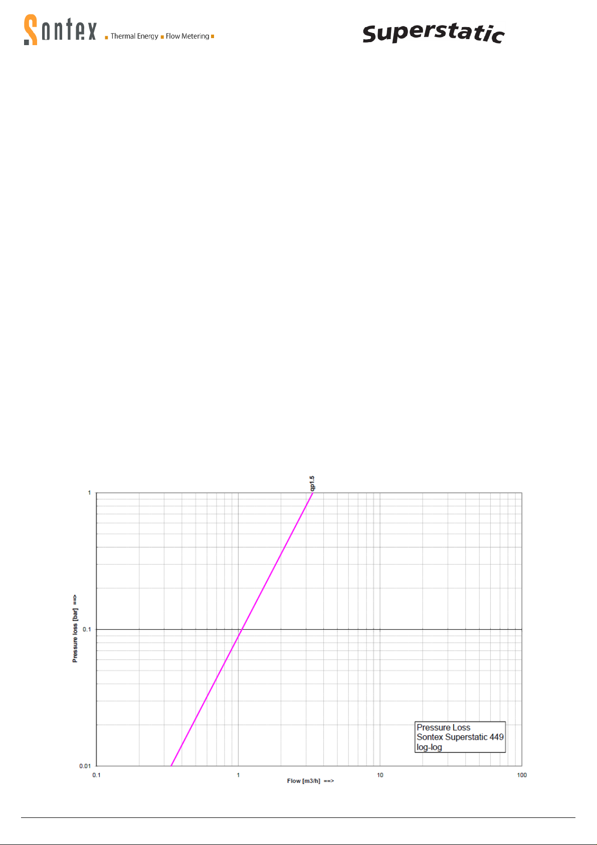
Druckverlustkurve Pressure Loss Curve
The integrator is manufactured and tested according to EN 61010 safety
control for measuring units and left the factory in perfect safety technical
condition. To maintain this status and to guarantee safe operation of the
integrator, the user must respect the instructions contained in this document.
When opening covers or removing parts, parts under power can be accessed. Further connection terminals can be under power. All repair and
maintenance work may be only implemented by a trained and an authorized
specialist. If the housings and/or the connecting cable show any damage, the
integrator unit should be disconnected and secured against accidentally
reset up – put in operation. Generally, avoid an installation situation with an
accumulation of heat above average. An above average heat buildup affects
substantially the lifetime of the electronic components.
Heat meters are measuring devices and must be handled with care.
To protect the unit against damage and contamination, the packing should
be only removed at the moment of installation.
For cleaning just use water moistened cloth and no solvent.
The connecting and connection cable may not be fastened on the pipe and
under no circumstances be isolated together with the pipe.
Function test
After opening the shutoff devices the installation must to be examined for
any leakage. By repeated pressing of the orange user button, various operating parameters e.g. flow, power, as well as supply and return temperature
can be read from the LCD display of the integrator unit. The communication
indicator on the LCD display serves for the test of the communication input
or output. With the software Prog449 the communication outputs can be
simulated. The flow can be tested with the help of the flow indicator. The
dynamics of the flow measurement can be tested with the help of the current
flow display in connection with a flow control.
Several displayed parameters serve to control the meters and/or to
adjust the installation. It has to be verified that the established flow of
the system does not exceed the maximum permitted flow of the meter.
For a comprehensive functional analysis, it is recommended to read
the startup protocol by means of the optical interface and reading
software
0449P300 Installation Superstatic 449 DE EN 19-01-2012 3 Sontex SA, 2605 Sonceboz, Schweiz, Switzerland
Page 4
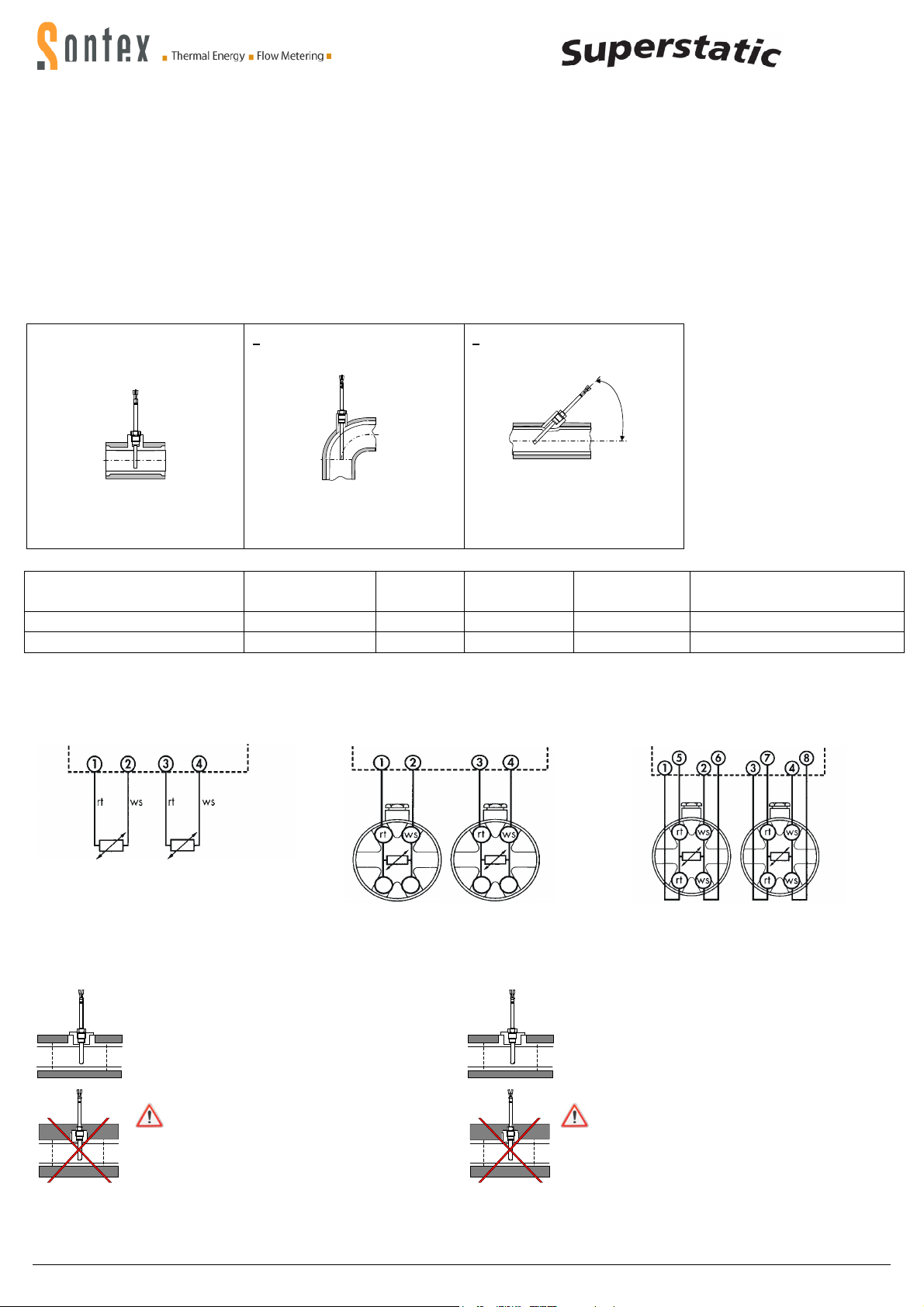
Temperaturfühlermontage
Temperature sensors mounting
2-Leiter Kabelfühler / 2 wire cable sensor
4-Leiter Fühler mit 2
-
Leiter Rechenwerk
4-Leiter Fühler mit 4
-
Leiter Rechenwerk
Die auf dem Typenschild der Temperaturfühler angegebenen Temperaturen sind zu beachten. Die Temperaturfühler sind immer gepaart abgestimmt. Sie werden nur gepaart geliefert und dürfen nicht getrennt, verlängert oder gekürzt werden, da dies die Messgenauigkeit beeinflusst. Bei
Temperaturfühlerpaaren mit einer Kabellänge länger als 3 m, empfehlen
wir ausschließlich den Einsatz von geschirmten Temperaturfühlerpaaren. In
diesem Fall muss die Abschirmung korrekt angelegt werden. Temperaturfühler mit Tauchhülsen müssen bis zum Anschlag eingeführt werden –
anschließend fixieren. Bei ungleichen Kabellängen oder länger 6 m empfehlen wir ausschliesslich die Vierleitertechnik. Die Temperaturfühler können wahlweise in Tauchhülsen oder direkt ins Heizungs- bzw. Kühlmedium
montiert werden beide aber immer gleich. Eine asymmetrische Montage,
ein Fühler direkt und der andere mit Tauchhülse, ist NICHT zulässig.
Der messaktive Bereich der Temperaturfühlerspitze muss sich in der Mitte
des Rohrleitungsquerschnitts befinden.
DN15, 20, 25
Einbau im T-Stück
Installation in T-fitting
< DN 50
Einbau in Schweissmuffe 90°
Installation with welding sleeve 90°
Temperaturfühler senkrecht zur Achse der
Rohrleitung in der selben Ebene
Temperature sensor perpendicularly to the axis
of the piping in the same level
Temperaturfühlerachse übereinstimmend mit der
Rohrachse
Temperature sensor axle coincide with the tubing
axle
The temperatures indicated on the identification plate of the temperature
sensors are to be observed. The temperature sensors are always paired.
Only matched pairs are supplied and may not be separated, extended or
shortened, since this affects the measuring accuracy. With temperature
sensor pairs with a cable length longer than 3 m, we exclusively recommend the use of shielded temperature sensor pairs. In this case, the
shields must be installed correctly. Temperature sensors with protection
pockets must be inserted up to the stall – and fixed afterwards. With unequal cable lengths or longer than 6 m we recommend exclusively the use of
four-wire technology. The temperature sensors can be installed alternatively in protection pockets or directly in the heating and/or cooling agent however always both in the same way. Asymmetrical mounting, one sensor
direct the other with pockets, is NOT permitted The measuring tip of the
temperature sensor part must be positioned in the center of the cross
section of the pipe
< DN 50
Einbau in Schweissmuffe 45°
Installation with welding sleeve 45°
4
5
°
Temperaturfühlermesselement eingetaucht in die
Rohrachse
Temperature sensor measuring element submerged onto the tubing axle
Zuordnungsliste Tauchhülsen / Allocation list sensor pockets
Temperaturfühler Versionen Tauchhülse Artikelnummer
Temperature sensor Versions Pocket Part number Temperature range
Material
Temperaturbereich
Ø 6x31mm Pt100, Pt500 G3/8" 0460A202 Messing/Brass 0…100 °C
Anschlussschema Temperaturfühler / Temperature sensors connections
1 / 2 Temperatur hoch / temperature high
3 / 4 Temperatur tief / temperature low
Ø 6x31mm Pt100, Pt500 G1/2" 0460A206 Messing/Brass 0…100 °C
4 wire sensor with 2 wire integrator
1 / 2 Temperatur hoch / temperature high
3 / 4 Temperatur tief / temperature low
4 wire sensor with 4 wire integrator
1 / 5 + 2/ 6 Temperatur hoch / temperature high
3 / 7 + 4/ 8 Temperatur tief / temperature low
Kabelquerschnitte für Kopffühler ≥ 0,5 mm2 (EN 1434-2) / Wire cross section for head sensors ≥ 0,5 mm2 (EN 1434-2)
Temperaturfühlereinbau bei Kälteanlagen
Die Isolation darf nur bis zur Temperaturfühlerver schraubung vorgenommen werden.
Die Verschraubung der Temperaturfühler darf auf keinen
Fall mit isoliert werden. Dies gilt auch, wenn der Tempera turfühler direkt im Durchflusssensor montiert ist.
Temperature sensor installation with cooling applications
The isolation may be made only up to the temperature
sensor screw connection.
The screw connection of the temperature sensors may
in no case be isolated with. This applies even if the
temperature sensor is installed directly in the flow sensor.
0449P300 Installation Superstatic 449 DE EN 19-01-2012 4 Sontex SA, 2605 Sonceboz, Schweiz, Switzerland
Page 5

Fehlermeldungen
Error messages
Das Rechenwerk Supercal zeigt auf der LCD-Anzeige mit der Bezeichnung
Err und einem Zahlencode die anliegenden Fehlermeldungen an. Wenn
mehrere Fehler gleichzeitig anliegen, werden die Nummern der Fehlermeldungen summiert.
Err1 Der Vorlauffühler hat einen Kurzschluss oder Unterbruch
Err2 Der Rücklauffühler hat einen Kurzschluss oder Unterbruch
Temperaturfühler vertauscht bzw. Temperaturfühler im
kälteren Strang ist höher als im wärmeren Strang
Err4 Durchfluss zu hoch
Err8 Speicherfehler EEPROM im mess- und eichrelevanten Teil
(erst nach dem zweiten mal aktiv)
Err16 Speicherfehler EEPROM im Rechenwerkunterteil
(erst nach dem zweiten mal aktiv)
Err32 Konfigurationsfehler EEPROM im mess- und eichrelevanten Teil
Err64 Konfigurationsfehler EEPROM im Rechenwerkunterteil
Err128 Interner Elektronikfehler, zurück zum Hersteller
Err256 Spannungsausfall (bei Netz- oder Busversorgung)
Err512 Defektes Kommunikationsmodul Steckplatz 1
Err1024 Defektes Kommunikationsmodul Steckplatz 2
Err2048 Fehler Impulseingang Zusatzzähler A1
Err4096 Fehler Impulseingang Zusatzzähler A2
Err8192 Interner Elektronikfehler, zurück zum Hersteller
Liegt ein Fehler mehr als eine Stunde an, so wird er im Fehlerspeicher mit
Datum und Uhrzeit (Fehleranfang) und Dauer (in Minuten) abgespeichert.
Wenn ein Fehler weniger als 60 Minuten anliegt, so wird er automatisch und
ohne Speicherung gelöscht.
Die zwei Temperaturfühlerindikatoren werden bei der kumulierten Energieanzeige auf dem Hauptmenü angezeigt, wenn:
- die Temperaturfühler vertauscht sind dieser Anlagenzustand tritt bei den
meisten Installationen während der Sommerzeit auf
- die Temperatur im kälteren Strang höher ist als im wärmeren Strang.
Sämtliche Fehlermeldungen werden 60 Sekunden nach der FehlerBeseitigung automatisch auf der LCD-Anzeige gelöscht.
Optionale Kommunikationsmodule
Das Rechenwerk kann mit bis zu zwei verschiedenen optionalen Kommunikationsmodulen nachgerüstet werden. Die optionalen Kommunikationsmodule können nachbestückt werden, ohne dass die eichamtliche Prüfung
verletzt wird. Die Optionsmodule sind rückwirkungsfrei auf den eichrelevanten Teil im Rechenwerkdeckel. Spätestens 10 Sekunden nach der Montage
erkennt das Rechenwerk die eingesteckten Optionsmodule und ist für die
Funktionen frei verfügbar. Beim Anschluss der Kommunikationsmodule ist
die mitgelieferte Installationsanleitung zu beachten.
Parametrierungen
Durch setzen eines Jumpers auf der Hauptplatine auf dem Steckplatz JP1
wird der Parametrier- und Testbetrieb aktiviert. Über die 2 Bedientasten auf
dem Rechenwerk können Datum und Zeit, Kundennummer und die M-Bus
Primäradresse geändert werden. Der Stromverbrauch ist im Parametrierund Testbetrieb grösser als im Normalbetrieb, also Jumper unbedingt wieder entfernen nach Abschluss der Parametrierungen.
Weitere Parameter können mit der Software Prog449 geändert werden
abhängig von den Berechtigungen und ohne Setzen des Jumpers.
Kühlmittel (Glykol)
Für Kälteanwendungen mit Kühlmittel-Wassergemischen ist ausschliesslich der Kältezähler Superstatic 440 zu verwenden.
The integrator indicates occurring errors by displaying on the LCD the Errsign together with a numbered code. If several errors occur at the same
time, the numbers of the error codes are added.
Err1 The supply sensor is short circuited or disconnected
Err2 The return sensor is short circuited or disconnected
The temperature sensors are switched; the temperature sensor in the
cooler line is higher than the temperature sensor in the warmer line
Err4 Flow rate too high
Err8 EEPROM error in the integrator base
(only active after the second incident)
Err16 EEPROM error in the measurement and calibration part
(only active after the second incident)
Err32 Configuration error into the measurement and calibration part
Err64 Configuration error into the integrator base
Err128 Internal electronic failure, return to manufacturer
Err256 Tension drop (by mains supply or bus supply)
Err512 Defective communication module connection place 1
Err1024 Defective communication module connection place 2
Err2048 Error pulse inputs additional meter A1
Err4096 Error pulse inputs additional meter A2
Err8192 Internal electronic failure, return to manufacturer
If an error lasts longer than an hour the error will be registered in the error
register with its date and time (beginning) and duration (in minutes). When
an error lasts less than 60 minutes the error will be automatically deleted
without being memorized.
The two temperature indicators are displayed on the cumulated energy
by the main menu when:
- Temperature sensors are switched this installation error mode happen
with most installations during the summer time
- Temperature in the cooler line is higher than the one in the warmer line.
These error messages are automatically deleted from the LCD display 60
seconds after the error has been removed.
Communication options
The integrator can be fitted with up to two different optional communication
modules. The optional communication modules can be equipped afterwards, without damaging the verification. The optional modules have no
influence on the verified relevant part in the cover of the integrator unit. At
the latest 10 seconds after the installation, the integrator unit recognizes
the plugged in optional modules and the functions are freely available.
When connecting the communication modules, the installation guidance supplied with the unit - is to be considered.
Parameter mode
By plugging a jumper on the main board, position JP1, the parameter and
test mode is activated. With the 2 buttons on the integrator date and time,
customer number and the M-Bus primary address can be modified. The
current consumption is higher with the parameter and test mode than in the
normal mode, thus it’s important to remove the jumper after the parameterisation.
Additional parameters can be modified with the software Prog449 depending on the user rights but without plugging the jumper.
Cooling liquids (Glycols)
For cooling applications with cooling liquids water mixtures exclusively use the Superstatic 440.
0449P300 Installation Superstatic 449 DE EN 19-01-2012 5 Sontex SA, 2605 Sonceboz, Schweiz, Switzerland
Page 6
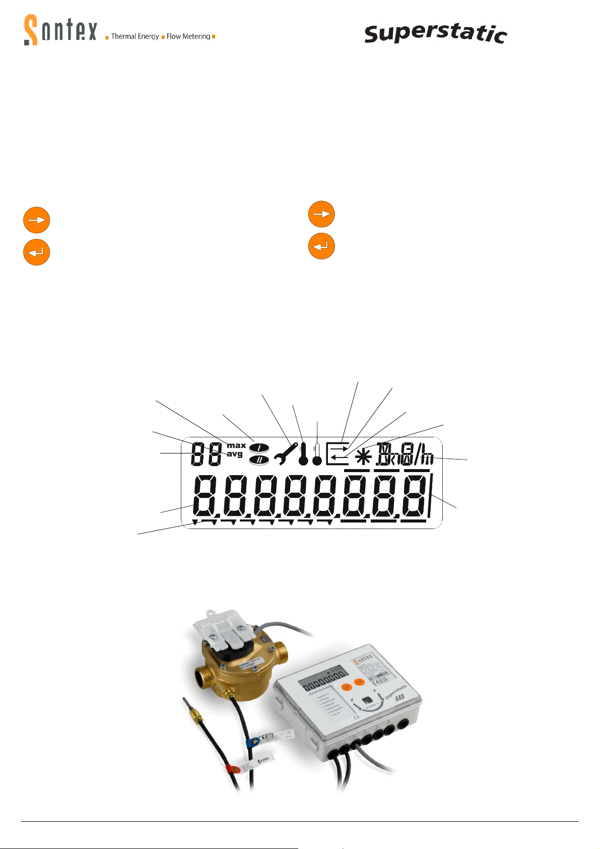
Anzeige
Display
Statischer Wärmezähler Supestatic 449
Das Rechenwerk verfügt über folgende Anzeigeebenen: siehe Etikette
unterhalb der Anzeige
- Favoritenmenü (sofern aktiviert)
- Hauptmenü (Abrechnungsrelevante Daten)
- Stichtage
- Monatswerte
- Mittelwerte
- Maximalwerte
- Konfiguration
- Service
Die Anzeigeebenen können kundenspezifisch in der Anzahl sowie in der
Reihenfolge der Anzeigesequenzen parametriert werden. Aus diesem
Grund können Abweichungen im Bereich der Anzeigeebenen und der Reihenfolge der Anzeigesequenzen möglich sein.
LCD-Bedienkonzept
Mit der Pfeiltaste können Sie die verschiedenen Menüs oder
die Positionen innerhalb der Menüs ansteuern. Im Prüfbetrieb
können Sie auch die Zahlen von 0...9 mit der Pfeiltaste erhöhen.
Durch Drücken der Entertaste können Sie das Menü oder die
Position bestätigen.
Wenn Sie die Entertaste gedrückt halten (beliebige Position
und/oder Menü), können Sie durch Drücken der Pfeiltaste auf
die verschiedenen Ebenen zurückkehren oder durch gleich
zeitiges Drücken der Entertaste und Pfeiltaste kehren Sie auf
die vorherige Menüposition zurück.
Nach 3 Minuten schaltet die Anzeige des Rechenwerkes automatisch auf
das Hauptmenü zurück.
LCD (Liquid Crystal Display)
Maximalwerte
Maximum values
Mittelwerte
Average values
Index für die Monats-, Mittel- und
Maximalwerte
Index for the monthly, average
and maximum values
Tarif 1 und Tarif 2
Tariff 1 and tariff 2
Werte ändern
Edit Values
The integrator Supercal has the following display sequence:
See label below the display
- Favorite menu (if activated)
- Main menu (Billing relevant data)
- Set days
- Monthly values
- Average values
- Maximal values
- Configuration
- Service
The display levels can be customized; in number and in order of the display
sequences. For this reason deviations can be possible in the range of the
display levels and the order of the display sequences.
LCD control concept
With the arrow key you can address the different menus or the
positions within a menu. In the verification mode you can also
increment with the arrow key the digits from 0...9.
By pressing the enter key you can confirm the menu or the
position.
When you keep pressing the enter key, you can by pressing
the arrow key (at any Pos. and/or menu) get back to the different
levels or by simultaneously pressing the enter key and the arrow
key you can get back to the previous menu position.
After 3 minutes the display of the integrator switches automatically back to
the main menu.
Indikator Messung Energie
Indication measurement energy
Temperatur hoch
Temperature high
Temperatur tief
Temperature low
Ausgangskommunikation
Output communication
Eingangskommunikation
Input communication
Durchflussindikator
Flow indication
Einheiten
Units
Anzeigeziffern
Display figures
Index für die Menüführung
Index for menu guidance
1 2 3 4 5 6 7
Static Heat Meter Superstatic 449
Rahmen Nachkommastellen
Frame for decimal figures
0449P300 Installation Superstatic 449 DE EN 19-01-2012 6 Sontex SA, 2605 Sonceboz, Schweiz, Switzerland
Page 7
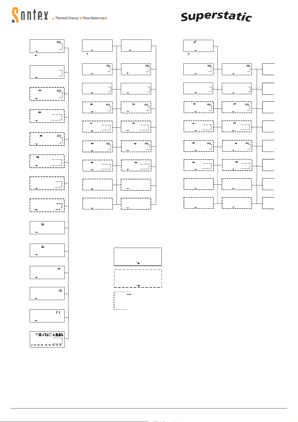
Haupmenü Stichtagsmenü Monatswerte
Main menu Set day menu Monthly values
000432i.0
1 2 3 4 5 6 7
Kumulierte Energie
Cumulated energy
3
M
000382.00
Kumuliertes Volumen
Cumulated volume
000i38i.0
Kumulierte Energie Tarif 1
Cumulated energy tariff 1
3
M
000382.00
Kumuliertes Volumen Tarif1
Cumulated volume tariff 1
00003i2.0
Kumulierte Energie Tarif 2
Cumulated energy tariff 2
3
M
000332.00
Kumuliertes Volumen Tarif 2
Cumulated volumen tariff 2
A I
000002.10
Kum. Wert Impulseingang 1
Cum value pulse input 1
A 2
003280.90
Kum. Wert Impulseingang 2
Cum value pulse input 2
°
C
D AS i
0i.07.2005
1 2 3 4 5 6 7
Datum Stichtag 1
Date set day 1
S i
000432i.0
Energie Stichtag 1
Energy set day 1
S i
3
M
000382.00
Volumen Stichtag 1
Volume set day 1
S i
000i38i.0
Energie Tarif 1 Stichtag1
Energy tariff 1 set day 1
S i
3
M
000382.00
Volumen Tarif1 Stichtag1
Volume tariff 1 set day1
S i
00003i2.0
Energie Tarif 2 Stichtag 1
Energy tariff 2 set day 1
S i
3
M
000382.00
Volumen Tarif2 Stichtag1
Volumen tariff 2 set day1
S i
A I
0000382i
Impulseingang1 Stichtag1
Pulse input 1 set day1
S i
A 2
00328090
Impulseingang 2 Stichtag 1
Pulse input 2 set day1
0i.0i.2006
Datum Stichtag 2
Date set day 2
S 2
000832i.0
Energie Stichtag 2
Energy set day 2
S 2
00i282.00
Volumen Stichtag 2
Volume set day 2
S 2
000i87i.0
Energie Tarif 1 Stichtag2
Energy tariff 1 set day 2
S 2
000562.00
Volumen Tarif1 Stichtag 2
Volume tariff 1 set day 2
S 2
00004i2.0
Energie Tarif 2 Stichtag 2
Energy tariff 2 set day 2
S 2
001232.00
Volumen Tarif 2 Stichtag2
Volume tariff 2 set day 2
S 2
000053i0
Impulseingang1 Stichtag2
Pulse input 1 set day 2
S 2
00648090
Impulseingang 2 Stichtag 2
Pulse input 2 set day 2
D AS 2
01
D A
0i.--.----
1 2 3 4 5 6 7
Speichertag Monatswerte
Storage day mounthly values
01
000832i.0
Letzter Monastwert Energie
3
M
Last monthly value energy
01
3
M
000782.00
Letzter Monatswert Volumen
Last monthly value volume
01
000232i.0
Letzter Monatsw. Energie Tarif 1
3
M
Last monthly value energy tariff 1
01
3
M
000382.00
Letzter Monatsw. Volumen Tarif 1
Last monthly value volume tariff 1
01
00003i2.0
Letzter Monatsw. Energie Tarif 2.
3
M
Last monthly value energy tariff 2
01
3
M
000332.00
Letzter Monatsw. Volumen Tarif 2
Last monthly value volume tariff 2
A I
01
A I
00002i30
Letzter Monatsw. Impulseingang1
Last monthly value pulse input 1
A 2
01
A2
000032i0 00648090
Letzter Monatsw. Impulseingang 2
Last monthly value pulse input 2
80.3 20.i
Temperatur hoch / tief
Temperature high / low
60.20
Temperaturdifferenz
Temperature difference
K
Legende
Legend
Standardanzeige
Standard indication
02
00i872i.0
Energie vor einem Monat
Energy one month ago
02
3
M
000862.00
Volumen vor einem Monat
Volume one month ago
02
000i32i.0
Energie Tarif 1 vor einem Monat
Energy tariff 1 one month ago
02
3
M
000682.00
Volumen Tarif 1 vor einem Monat
Volume tariff 1 one month ago
02
00003i2.0
Energie Tarif 2 vor einem Monat
Energy tariff 2 one month ago
02
3
M
001232.00
Volumen Tarif 2 vor einem Monat
Volume tariff 2 one month ago
02
A I
00i653i0
Impulseingang 1 vor einem Monat
Pulse input 1 one month ago
02
Impulseingang 2 vor einem Monat
Pulse input 2 one month ago
A2
03-15
03-15
03-15
03-15
03-15
03-15
03-15
03-15
23.900
Leistung
Power
42.355
Durchfluss
Flow
LC
-y 0
Glykol Kurve
Glycol curve
3
M
Einbauort
Mounting position
03-32
Wird nur angezeigt wenn die Option verfügbar ist
Only indicated if the option is available
Weitere Werte innerhalb des Menüs abrufbar:
3 - 15 Monatswert
3 - 32 Mittelwert
3 - 32 Maximalwert
Further values within the menu available:
3 - 15 monthly values
3 - 32 average values
3 - 32 maximum values
88
88888.888
Segmenttest
Segment test
0449P300 Installation Superstatic 449 DE EN 19-01-2012 7 Sontex SA, 2605 Sonceboz, Schweiz, Switzerland
Page 8
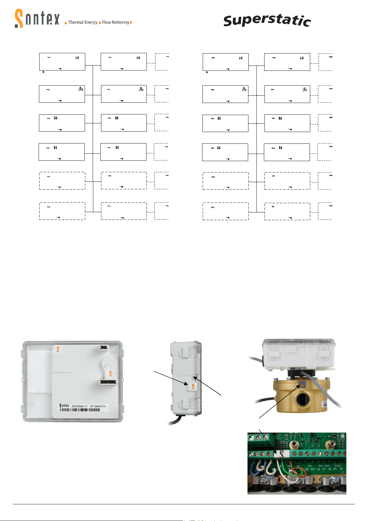
Plombierungen
Security seals
- Empfehlung für die Plombierung
- Recommendations for
sealing
1
2
Mittelwerte Maximalwerte
Average values Maximum values
0 I
00048.225
1 2 3 4 5 6 7
Mittelwert 1 Leistung
Average value 1 power
0 I
3
M
00932.200
Mittelwert 1 Durchfluss
Average value 1 flow
°
0 I
C
72.0 56.0
Mittelwert 1 Temperatur hoch/tief
Average value 1 temperature high/low
0 I
K K
i6.00
Mittelwert 1 Temperaturdifferenz
Average value 1 temperature difference
0 I
A I
120
Mittelwert 1 Impulseingang 1
Average value 1 pulse input 1
0 I
A 2
345
Mittelwert 1 Impulseingang 2
Average value 1 pulse input 2
02
00053.525
Mittelwert 2 Leistung
Average value 2 power
02
M
00622.250
Mittelwert 2 Durchfluss
Average value 2 flow
02
66.0 48.0
Mittelwert 2 Temperatur hoch/tief
Average value 2 temperature high/low
02
i8.00
Mittelwert 2 Temperaturdifferenz
Average value 2 temperature difference
02
A I
i08
Mittelwert 2 Impulseingang 1
Average value 2 pulse input 1
02
A 2
248
Mittelwert 2 Impulseingang 2
Average value 2 pulse input 2
Sicherungsmassnahmen Safety Measures
03-32
0 I
00048.225
1 2 3 4 5 6 7
Maximumwert 1 Leistung
3
03-32
Maximum value 1 power
0 I
3
M
00932.200
Maximumwert 1 Durchfluss
Maximum value 1 flow
03-32
°
C
0 I
72.0 56.0
Maximumert 1 Temperatur hoch/tief
Maximum value 1 temperature high/low
03-32
0 I
K K
i6.00
Maximumwert 1 Temperaturdifferenz
Maximum value 1 temperature difference
03-32
0 I
A I
120
Maximumwert 1 Impulseingang 1
Maximum value 1 pulse input 1
03-32
0 I
A 2
345
Maximumwert 1 Impulseingang 2
Maximum value 1 pulse input 2
02
03-32
00053.525
Maximumwert 2 Leistung
Maximum value 2 power
02
3
M
03-32
00622.250
Maximumwert 2 Durchfluss
Maximum value 2 flow
°
C
02
03-32
°
C
66.0 48.0
Maximumwert 2 Temperatur hoch/tief
Maximum value 2 temperature high/low
02
03-32
i8.00
Maximum 2 Temperaturdifferenz
Maximum value 2 temperature difference
02
A I
03-32
i08
Maximalwert 2 Impulseingang 1
Maximum value 2 pulse input 1
02
A 2
03-32
248
Maximalwert 2 Impulseingang 2
Maximum value 2 pulse input 2
Da die Plombierungen länderspezifisch unterschiedlich sein können, sind
die lokalen Vorschriften zu beachten. Gegen allfällige Manipulation oder den
unbefugten Ausbau müssen der Wärmezähler, die Verschraubungen sowie
die Temperaturfühler und Tauchhülsen mit Benutzerplomben versehen
werden. Die Plomben dürfen nur durch autorisierte Personen entfernt werden. Bei Nichtbeachtung entfällt die Gewährleistungspflicht. Es ist wichtig,
dass die Plombierdrähte so kurz wie möglich ausgelegt werden und zur
Plombe gut gespannt sind. Nur so ist die Plombierung gegen unbefugten
Eingriff geschützt.
Ab Werk plombiert - Ex factory seals
1: Klebeplombe / Sticker seal
2: Drahtplombe / Wire seal
Seals are country specific; the local regulations must be respected.
Against possible manipulation or unauthorized dismantling, the heat meters, the screw connections, as well as the temperature sensors and pockets must be protected with user seals. The seals may be removed only by
authorized persons. By neglecting this precaution the guarantee obligation
is void. It is important that the seal wires are kept as short as possible and
are well strained towards the seals. Only this way, the seal is protected
against unauthorized interference.
Ab Werk plombiert - Ex factory seals
0449P300 Installation Superstatic 449 DE EN 19-01-2012 8 Sontex SA, 2605 Sonceboz, Schweiz, Switzerland
Page 9
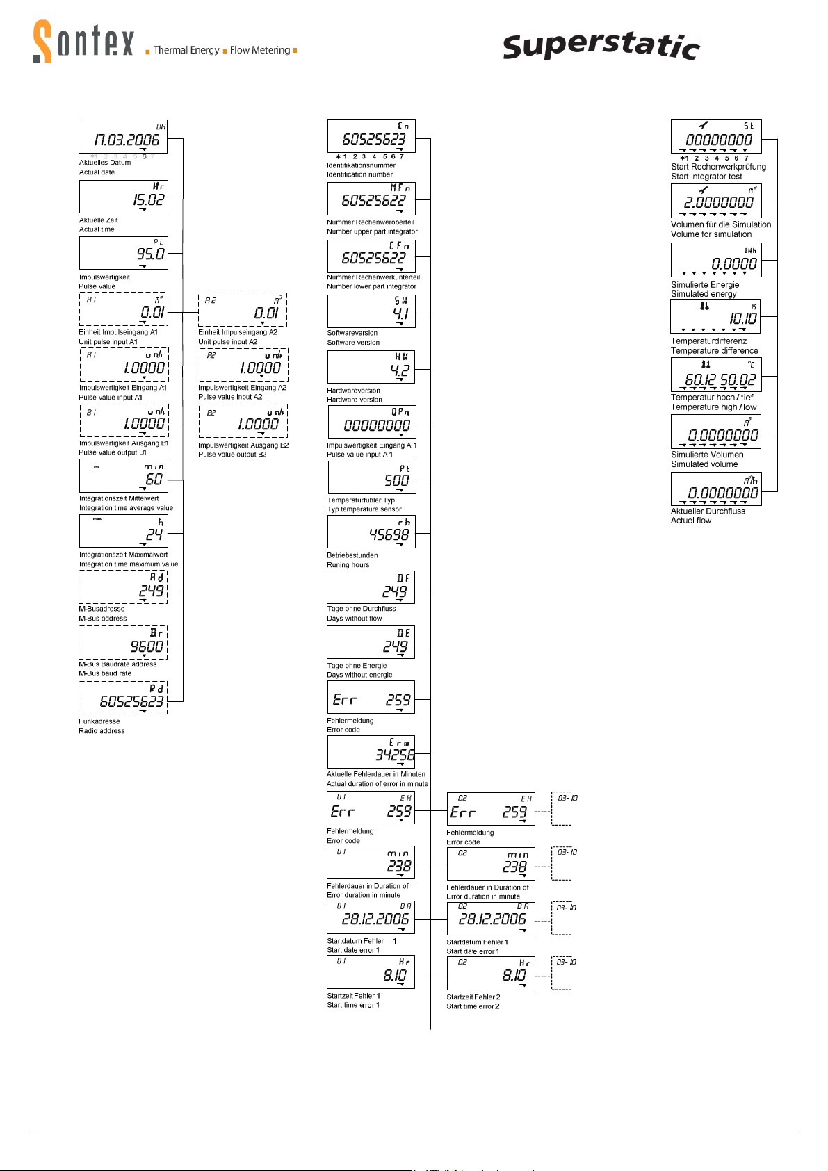
Konfiguration Service Prüfprogramm
Configuration Service Test mode
0449P300 Installation Superstatic 449 DE EN 19-01-2012 9 Sontex SA, 2605 Sonceboz, Schweiz, Switzerland
Page 10
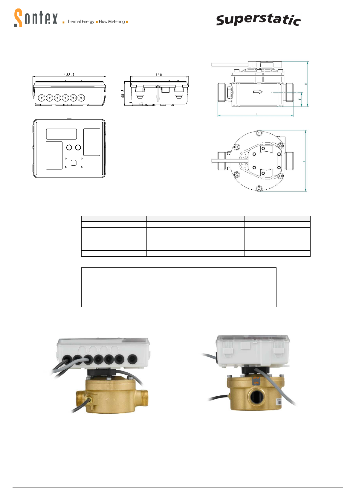
¾” 16 70 60
1.5 m
3
/h ¾” 16 89 65 110 21
1.5 m
3
/h 1” 16 89 65 130 21
Massbilder statischer Wärmezähler Superstatic 449 Dimensions heat meter Superstatic 449
Rechenwerk / Integrator
Schwingstrahl Durchflusssensor / Fluid oscillator flow sensor
qp G PN l (mm) H (mm) L(mm) E (mm)
*0.6 m3/h
*1.5 m3/h 1”
*2.5 m3/h 1”
*2.5 m3/h 1”
*In Vorbereitung / under way
Betriebstemperatur-Temperatur, dauernd /
Operating Temperature, permanent
Empfohlene Einlaufstrecken / Inlet straigt section (EN 1434)
Verbindung zwischen Durchflusssensor und Rechenwerk
Connection between flow sensor and integrator
110
16 89 65 190
16 89 65 130
16 89 65 190
90°C
3D für / for : L=110mm
0D für / for : L=130mm
0D für / for : L=190mm
0.8 m; fest / fix
18
21
21
21
Superstatic 449: Max. 140 x 110 x 112 [mm]
0449P300 Installation Superstatic 449 DE EN 19-01-2012 10 Sontex SA, 2605 Sonceboz, Schweiz, Switzerland
Page 11

Low flow
Technische Daten Durchflusssensor Superstatic 449 Technical Data Flow Sensor Superstatic 449
qp
Gewinde-
Anschluss
Ein-
bau-
Länge
Mat. PN
Maximal
Durchfluss
qs
Minimal
Durchfluss
qi
Ansprec-
Grenze
(50°C)
Fühler-
Einbau-
Platz
Gew.
Druck-
abfall
bei qp
qp Threaded connection Length Mat. PN
m3/h
*0.6
1.5 3/4"
1.5 1"
*1.5
*2.5
*2.5
* In Vorbereitung / under way Messing : Brass
Der Superstatic 449 kann ab 0.8 bar Rohrdruck eingesetzt werden. The flow sensor Superstatic 449 can be operated from 0.8 bar pipe pressure.
G" DN mm
(EN ISO
228-1)
3/4" (15) 110 Brass 16 1,2 6 - Yes - -
(15)
(20)
1" (20) 190 Brass 16 3 15 10 Yes - 1" (20) 130 Brass 16 5 25 - Yes - 1" (20) 190 Brass 16 5 25 - Yes - -
110 Brass 16 3 15 10 Yes 1.3 0.2
130 Brass 16 3 15 10 Yes 1.4 0.2
Maximal
Durchfluss
qs
PN m3/h l/h l/h
Minimal
Durchfluss
qi
threshold
value
(50°C)
Threaded
hole for
sensor
Pressure
wt.
loss at
qp
kg bar
0449P300 Installation Superstatic 449 DE EN 19-01-2012 11 Sontex SA, 2605 Sonceboz, Schweiz, Switzerland
Page 12
osition
Vertikale Einbaulage
Montage in Steig
- oder Fallrohren möglich.
Nach dem Einbau und vor der Inbetriebnahme, System > 10 min. spülen
Bedingungen zur Einhaltung de
r Richtlinie2004/22/EG (
und Rücklauf und
vorzugsweise direkt einzubauen. Bei Verwendung von Tauchhülsen mü
die verwendeten Temperaturfühler konform
und Rücklauffühler müssen auf den Tauc
hülsenböden aufsitzen. Einbaustellen im Durchflusssensor können unter
symmetrischem Einbau der Temperaturfühler genutzt werden.
bau der Temperaturfühler ist NICHT zulässig.
konformitätsgekennzeichnete
gleichlang für den Vor
2. Deren Anschluss erfolgt
die gekennzeichneten Anschlussbereiche unter Beachtung der elektr
schen Kompatibilität Pt 100 bzw. Pt 500 des Rechenwerkes.
Durchflusssensor einz
Die Auswahl der Batterie hat so zu erfolgen, dass die
die Länge der geplanten Einsatzdauer und 1 Jahr Lagerfrist eine Verso
eständigkeit erfolgen unter den Bedingungen einer
Anforderungen FW 510. Im Fa
weichender Zusammensetzungen muss das Messgerät ausgebaut
und regelmäßigen Instandsetzungen gemäß der Instandsetzu
auf dem Durchflusssensor sind im Lieferu
sich die Halterung
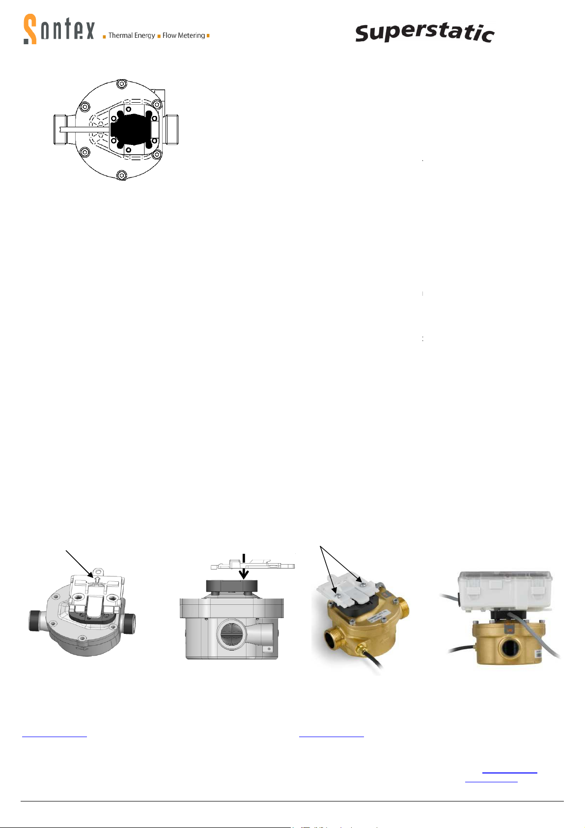
Rechenwerkes in 4 verschiedenen Positionen, jeweils um 90° gedreht,
so montiert sein, dass der
Pfeil / Arrow
Technische
Unterstützung
lokalen
CE
Konformitätserklärung
Die detaillierte Konformitätserklärung zum Herunterladen finden Sie auf unserer Homepage
The detailed declaration of conformity can be found and downloaded on our homepage
Sontex SA, 2605 Sonceboz, Schweiz, Switzerland
Vertical mounting position
Mounting in riser
or
down
pipes possible.
After mounting and before commissioning purge system >
MID )
Conditions to comply with the directive 2004/22/EU (MID)
The temperature sensors have to be
return and preferably without pockets. If using pockets they must be in a
cordance with the conformity declaration. Flow and return sensors must
be mounted to the bottom of the pockets. Installation places in the flow
sor can be used with the symmetrical installation of the temperature
Asymmetrical mounting of the temperature sensor is
For the exchangeable temperature sensor pairs according to MID the
The w
onnection to the integrator according to terminal connection
on page 2 by respecting the electrical compatibility Pt 100 and Pt 500 of
traight section of piping of 3 DN in flow of any flow
The selection of the battery has to take placed in such a way that it pe
mits at least a supply of auxiliary energy over the duration of the applic
Information about the measuring stability is
water measurement in accordance with AGFW requirements FW 510. In
case of deviating compositions the measuring instrument must be submi
ted to periodic control according to the guidelines of Sontex.
ator on the flow sensor
delivery whereby the bracket in the back of the
4 different positions, turned by 90° respectively.
must be mounted on the flow sensor that the
2 Schrauben / 2 Screws
Technical
support
local Sontex agent or Sontex SA d
Horizontale
Einbaulage
bezogen auf die Rohrachse liegen,
um Einflüsse durch allfällige Lufteinschlüsse (oben) oder Schmutz (unten)
The sensor head MUST be placed to the side +/
to avoid influences of air inclusions (top) or dirt (bottom).
Einbaulage horizontal - Horizontal mounting p
Allgemeiner Einbauhinweis:
um Lufteinschlüsse zu vermeiden.
- Die Temperaturfühler sind symmetrisch in den Vor-
sen diese ausschließlich für
tätsuntersucht sein. Die Vor-
rischer Ein
- Für die austauschbaren
beträgt deren maximale Länge,
m, für die Leitungsquerschnitte gilt EN 1434-
- Eine gerade Rohrstrecke von 3 DN ist vor dem
halten.
-
gung mit Hilfsenergie gestattet.
- Angaben zur Messb
Wasserzusammensetzung gemäß AGFWle ab
der Firma Sontex unterzogen werden.
Rechenwerkmontage
Für die Rechenwerkmontage
fang 2 Schrauben enthalten, mit denen
dem Durchflusssensor montieren lässt.
Die Halterung muss auf dem Durchflusssensor
Pfeil auf der Halterung sichtbar ist.
Der Messkopf MUSS seitlich +/- 45°
auszuschließen.
Horizontal Mounting position
axis
General notice for mounting:
bubbles.
si-
h-
Asymmet-
n Temperaturfühler
- und Rücklauf, 15
an
i-
u-
se mindestens über
r-
ngsrichtlinie
m-
im Rücken des
auf
sen
sensor pair.
NOT permitted.
maximum equal length is 15 m.
1434-2. The c
the integrator.
- A s
respected.
tion plus 1 year storage period.
-
l-
Mounting of integrator
To mount the integr
The bracket
bracket is visible
- 45° in relation to the pipe
10 min to avoid air
mounted symmetrically in flow and
c-
ire cross section is according to EN
meter must be
r-
a-
described in the conditions for
t-
2 screws are included in the
integrator can be mounted in
arrow on the
0449P300
Für technische Unterstützung wenden sie sich an die
tungen oder direkt an Sontex SA.
Hotline Sontex:
+41 32 488 30 04
Technische Änderungen vorbehalten
Declaration of conformity
0449P300 Installation Superstatic 449 DE EN 19-01-2012
Sontex Vertre-
12
For technical support contact your
rectly.
Hotline Sontex:
+41 32 488 30 04
Technical modifications subject to change without notice
www.sontex.ch/
www.sontex.ch
i-
 Loading...