

Page 1
FlowTracker2
®
Quickstart Guide
Handheld ADV ® for Velocity and Flow Measurements
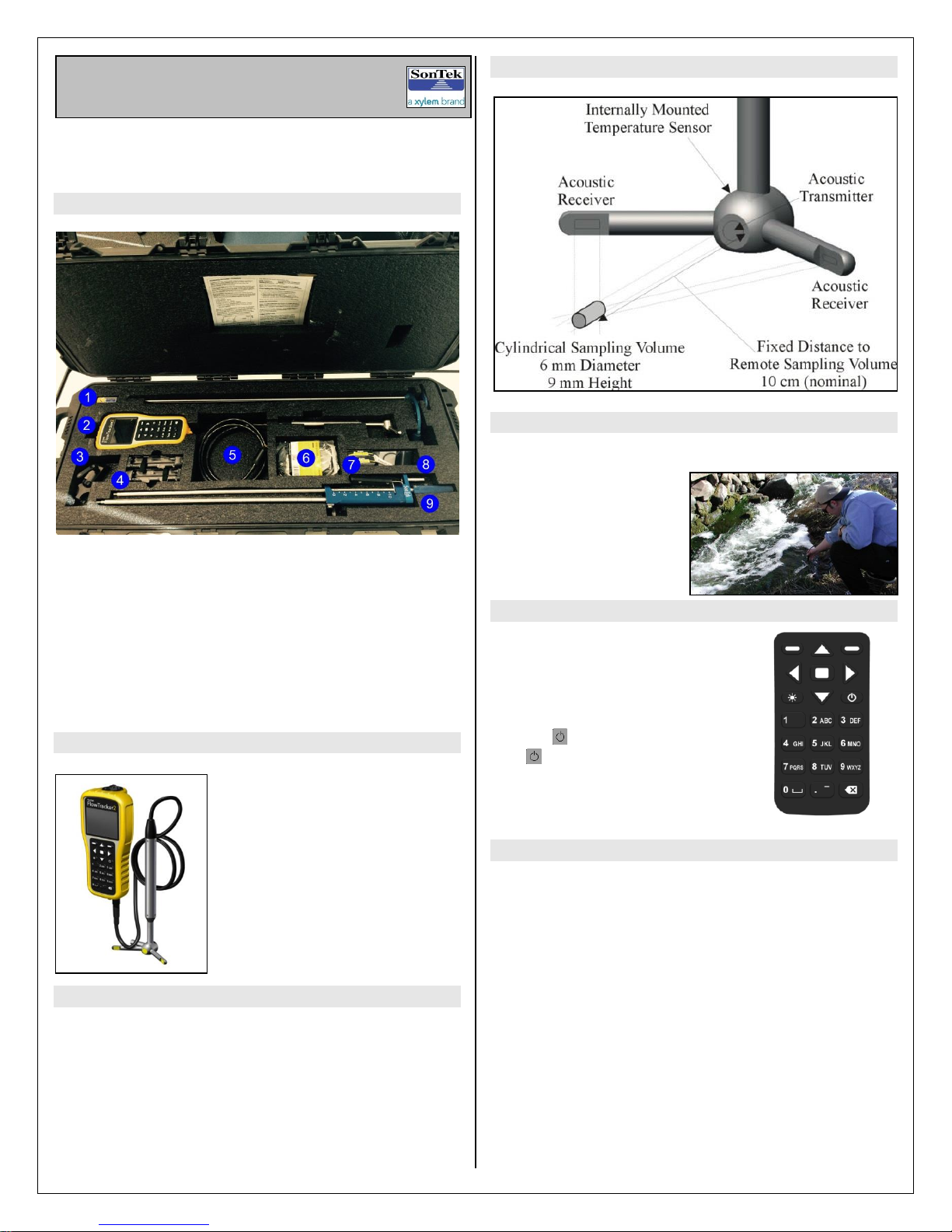
ADV Probe and Sampling Volume
This is a quick reference to FlowTracker2 operation. For
more information, refer to the FlowTracker2 Manual that
installs with the PC software.
What’s in the case?
1. Software USB Thumb Drive
2. FlowTracker2 Handheld
3. Handheld Mounting Bracket (optional)
4. AA Battery Holders (2)
5. FlowTracker2 ADV probe and cable
6. USB Communications Cable
7. AA Alkaline Batteries (8)
8. Battery compartment o-rings (2) & Silicon grease
9. SonTek Top Setting Wading Rod (optional)
What does the FlowTracker2 do?
The FlowTracker2 measures
velocities with a range as low as
0.001 m/s (0.003 ft/s) and up to
4.0 m/s (13 ft/s). When combined
with a wading rod, the
FlowTracker2 can be used to
measure the total discharge
across a river section.
How does it work?
The FlowTracker2 uses SonTek’s exclusive ADV®
technology to measure 2-D or 3-D velocities in a small
measurement point located 10 cm from the acoustic
transmitter. This allows measurement of natural flow that
is free of any disturbance caused by the instrument.
There are no moving parts on the FlowTracker2, so
calibration by the user is never required.
Where can I use a FlowTracker2?
The FlowTracker2 can be used in:
Natural streams
Weirs and Flumes
Open channels
Irrigation
Water treatment
Stormwater
Basic FlowTracker2 Operation
Install AA batteries in one of the two
holders provided. Loosen the battery
compartment cover on the top of the
handheld. Insert the battery holder
into the compartment. To turn the unit
on, hold for one second; to turn off,
hold for four seconds. Always
follow the on-screen instructions and
use the major key functions labeled
on the keypad.
Office Diagnostics
Before taking the FlowTracker2 into the field, there are
some office diagnostics that should be run to ensure the
system is working properly. First, plug the USB thumb
drive into a computer to install the FlowTracker2 desktop
software. The FlowTracker2 Manual installs with the
software. Section 7.1.3 discusses the diagnostic checks
within the Handheld Utilities menu. The diagnostics
include system functions, raw data and BeamCheck.
BeamCheck will require a bucket or small tub of water
about the size of a shoe box. Be sure the probe is not
resting on the bottom when collecting BeamCheck data.
The Automated BeamCheck option is recommended for
new users. A complete description of BeamCheck can be
found in Section 6.4 of the manual. Use Recorder to
download all files from the recorder and to format it prior to
data collection.
P/N 45-0110 Rev A Page 1
Page 2
Sampling
Volume
Y
X
Probe
Coordinate System
Graduated Tag Line
Primary Flow
Direction
Mounting
Pin
Mounting the Handheld
The handheld mounting bracket clamps onto the top of a
wading rod like the Top-Setting rod below:
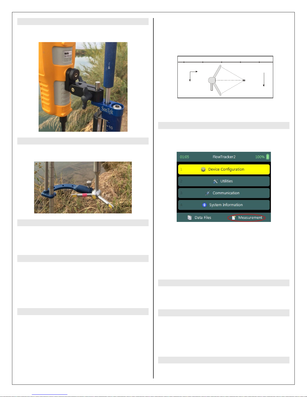
During the entire measurement, the probe’s X-axis must
be maintained perpendicular to the tag line. The probe
should be held away from underwater obstacles that may
disturb the flow. Do not turn the FlowTracker2 into the
direction of flow, as it will automatically account for flow
direction when making discharge measurements.
REW LEW
Based on the depth, station width, and mean velocity, the
discharge for a station is calculated. The total discharge is
the sum of all station and edge discharge values.
Making a Discharge Measurement
Mounting the Probe
The ADV probe mounting post slides into the bracket.
Tighten the thumbscrew to secure the probe.
Pre-Measurement Diagnostics
Prior to making a measurement, it is recommended that
the same diagnostics checked in the office are verified in
the field. The diagnostics are in the Utilities menu.
Discharge Measurement - Theory
Measuring discharge is the most common method of
collecting data with the FlowTracker2. It involves wading
across the stream/ river while taking measurements of
water depth and velocity at different locations (based on
ISO/USGS procedures). When combined with depth
information, the total discharge can be computed.
A discharge measurement can be started by clicking the
Measurement button at the bottom of the Main Menu.
Follow the on-screen prompts to enter the Site
Information and begin data collection. Section 8 of the
manual details the entire process. To enter the ending
edge location, add a station and change the station type to
the opposite bank from the start. Be sure to review data
from each station prior to completing the measurement. A
confirmation screen will appear notifying the user of any
QC warnings or missing end edge station.
Downloading Data
Connect via USB cable or Bluetooth to a PC running the
FlowTracker2 software. See Section 14.5 of the manual.
Discharge Measurement - Procedure
Select a site with reasonable uniform bottom conditions
that may be safely waded (typically no more than 1-m
deep). String a graduated tag line across the river
perpendicular to the riverbanks.
Start at one edge (REW or LEW) and enter the starting
location and water depth. Divide the river cross-section
into a number of stations appropriate for its width. At each
station, the operator enters the station location and water
depth and measures the velocity at one or more depths.
P/N 45-0110 Rev A Page 2
Viewing and Exporting Data
Once the files have been downloaded, click on the View
Data button to select and open file(s). Section 14.8 of the
manual covers data viewing options. There are postprocessing features outlined in Section 14.9 and export
options in Section 14.10.
Technical Support
 Loading...