

Page 1
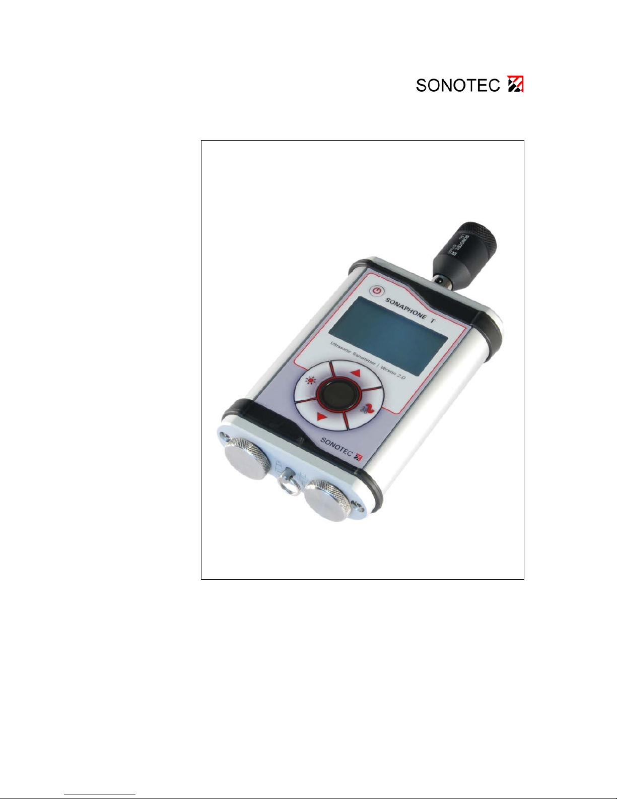
Ultrasonic Transmitter
SONAPHONE T Version 2.0
Operating Manual
Page 2

Manufacturer: SONOTEC Ultraschallsensorik Halle GmbH
Model: Ultrasonic transmitter
Type: SONAPHONE T
Version 2.0
SONOTEC Ultraschallsensorik Halle GmbH
Nauendorfer Straße 2
D - 06112 Halle (Saale)
Phone: +49 (0)345 133 17-0
Fax: +49 (0)345 133 17-99
© 2013
SONOTEC Ultraschallsensorik Halle GmbH
All rights reserved
The content of this manual is the property of SONOTEC Ultraschallsensorik
Halle GmbH and is protected by copyright. Duplication and distribution in
any form, particularly reprinting, photographic, mechanical or electronic
reproduction, or in the form of storage in data processing systems or data
networks, is prohibited without the consent of the copyright holder.
Version: 2 Revised: 2013-05-02
Page 3

Contents
1 Notes on the operating manual ................................................................................................. 4
1.1 General ............................................................................................................................... 4
1.2 Symbols used ...................................................................................................................... 4
2 Safety ............................................................................................................................................ 5
2.1 Safety information ............................................................................................................... 5
2.2 User qualifications ............................................................................................................... 5
3 Device description ...................................................................................................................... 6
3.1 Designated use ................................................................................................................... 6
3.2 Measuring method and functioning ..................................................................................... 6
3.3 Device construction ............................................................................................................. 6
3.4 Display and operating buttons ............................................................................................ 7
3.5 L50 ultrasonic air transducer ............................................................................................... 8
3.6 SONOSPHERE spherical transmitter (optional) ................................................................. 8
4 Commissioning and installing ................................................................................................. 10
4.1 Inserting the batteries ....................................................................................................... 10
4.2 Connecting the power supply unit ..................................................................................... 10
4.3 Installing probes ................................................................................................................ 10
4.4 Uninstalling probes ........................................................................................................... 11
5 Operating the SONAPHONE T ................................................................................................. 12
5.1 Switching the SONAPHONE T on and off ........................................................................ 12
5.2 Setting the sound intensity ................................................................................................ 12
5.3 Switching on modulation ................................................................................................... 12
5.4 Switching on the light ........................................................................................................ 12
5.5 Setting the display contrast and time ................................................................................ 13
6 Cleaning and care ..................................................................................................................... 14
7 Maintenance and troubleshooting ........................................................................................... 14
8 Technical data ........................................................................................................................... 15
Page 4
1 Notes on the operating manual
SONAPHONE T 4
1 Notes on the operating manual
1.1 General
Thank you for choosing the SONAPHONE T.
This manual forms part of the SONAPHONE T and should therefore be
stored in its imm ediate vicinity where it can be accessed by all oper ators at
any time. It contains all the information needed to ensure proper and efficient
use, along with all the instructions to ensure safe operation of the
SONAPHONE T.
1.2 Symbols used
Hazards or special information can be indicated in the following ways:
Warning!
This information warns of possible personal injury and damage to property.
Caution!
This information warns of possible damage to property.
Note
This symbol provides information or draws attention to special features.
Page 5
2 Safety
SONAPHONE T 5
2 Safety
2.1 Safety information
The SONAPHONE T is a state of the art product that complies with all
applicable safety regulations. The manufacturer has taken every possible
action to guarantee safe o peration. The user must ensure that safe us e is
not impaired. The device is factory tested and was delivered in a safe
operating condition.
Warning!
Incorrect operation and use of the SONAPHONE T ultrasonic transmitter
and its accessories can present a hazard for the user.
• The SONAPHONE T may only be operated with power sources in the
operating voltage range specified in the technical data.
• Operation and storage of the SONAPHONE T outside the
temperature ranges specified in the technical data is not permitted.
• The SONAPHONE T may not be immersed.
• The SONAPHONE T may only be exposed to a minimal risk of
mechanical hazard. If there is visible damage, the SONAPHONE T
must be taken out of operation immediately.
• It is not permitted to open the SONAPHONE T or accessories or to
undertake repair work on them without authorisation. This may only
be carried out by the manufacturer.
2.2 User qualifications
Warning!
The SONAPHONE T ultrasonic transmitter may only be installed and
operated by users who have read and understood the entire operating
manual.
Page 6
3 Device description
SONAPHONE T 6
3 Device description
3.1 Designated use
The SONAPHONE T is a special ultrasonic transmitter and serves as an
auxiliary device for ultraso nic detectors in the SONAPHONE series for leak
testing. The device provides detection of seal failures in windows, doors,
cabins, climatic cabinets, vehicles or containers, which have sealing
surfaces or rubber profile seals.
3.2 Measuring method and functioning
The SONAPHONE T transmits high-frequency signals in the ultrasonic
range. If you place t he ultrasonic transmitter for leak detection in a closed
system, the ultrasonic signals escape via leaks in the system and can be
identified there using an ultrasonic detector in the SONAPHONE series.
Modulation of the signal is used in cases where it is expected that
background noise will interfere with the sou nds being analysed. The s ound
intensity can be set ind ividually, so that both small and l arge leaks can be
located.
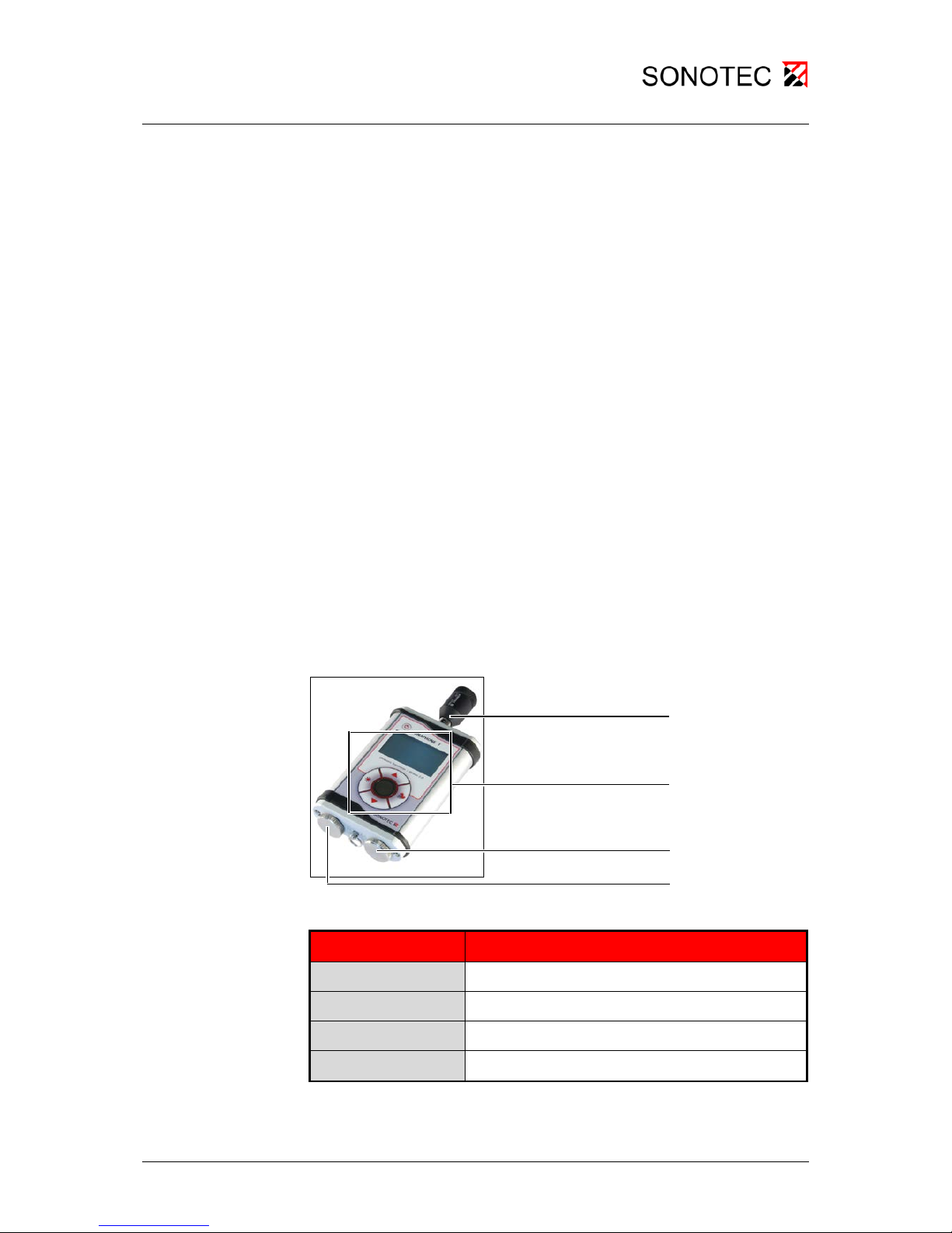
3.3 Device construction
Figure 1: SONAPHONE T ultrasonic transmitter
Item number Function
1
Slot for ultrasonic probes
2
Display and operating buttons
3
Connection for power supply unit
4
Battery compartment
Table 1: SONAPHONE T device elements
1
2
3
4
Page 7
3 Device description
SONAPHONE T 7
3.4 Display and operating buttons
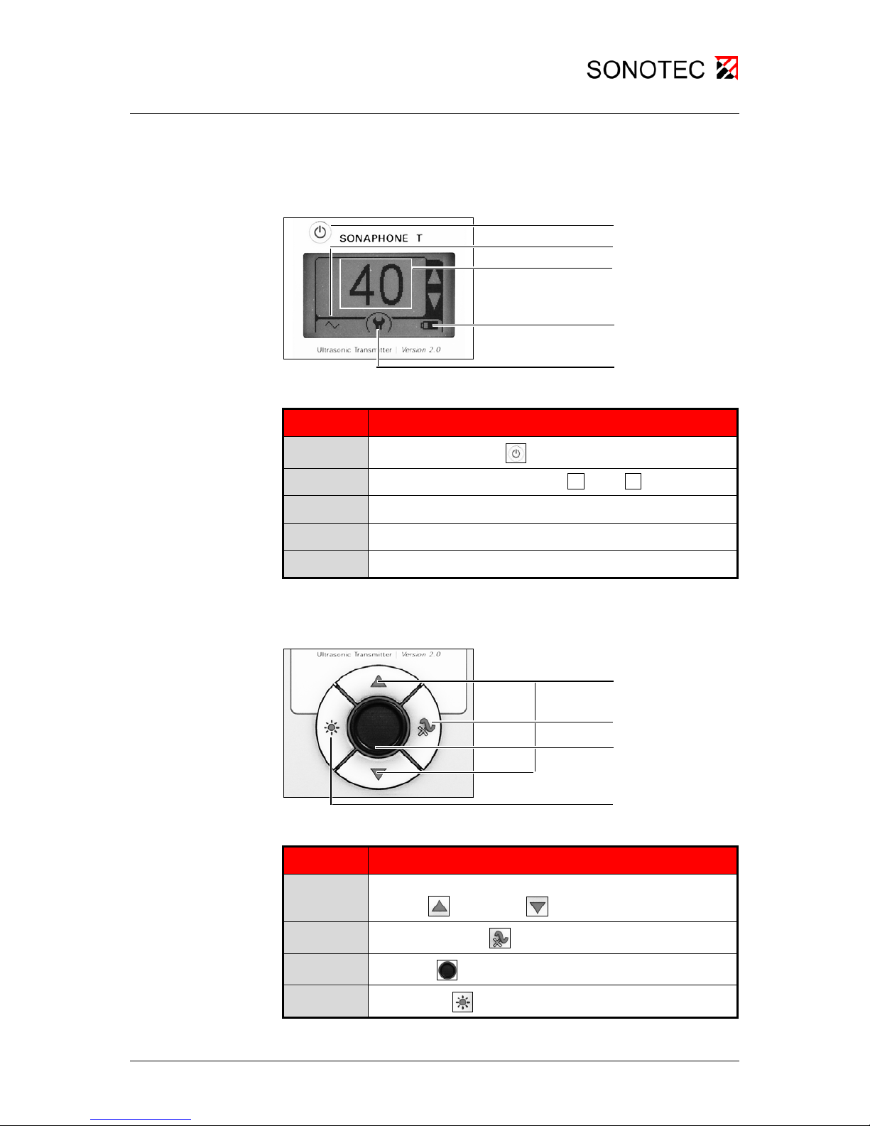
Description of the display elements:
Figure 2: Display
Function/view on the display
1
Device: On/Off button
:
2
Signal type view: Modulation On ~ or Off =
3
View of the current sound intensity
4
Battery status view
5
Function of the enter key in the menu
Table 2: Description of the display elements
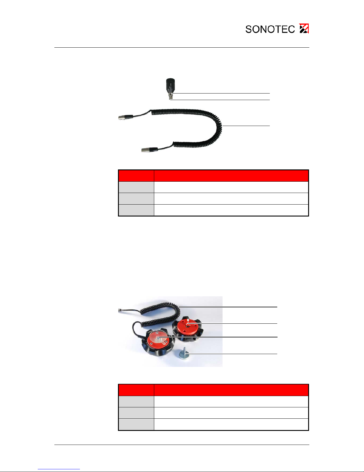
Description of the operating buttons:
Figure 3: Operating buttons
Function
1
Settings in the menu:
Increase
or decrease value
2
Modulation: On/Off
3
Enter key:
Switch to menu or confirm value
4
Light: On/Off
Table 3: Description of the operating buttons
1 2 34 1 2 4
5
3
Page 8
3 Device description
SONAPHONE T 8
3.5 L50 ultrasonic air transducer
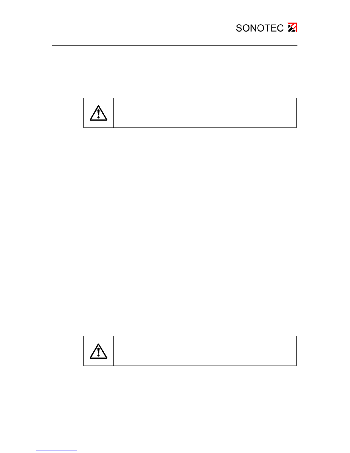
Figure 4: L50 airborne sound probe and extension
Function
1
Button for unlocking
2
Connector
3
Extension (optional)
Table 4: Elements of the airborne sound probe
3.6 SONOSPHER E sp h erica l transmitter
(optional)
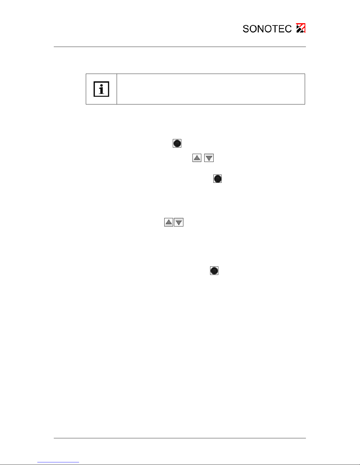
The SONOSPHERE spher ical trans mitter is used to te st large and cont orted
areas. Depending on requ irements, it can be used as a semi-sphere with 7
transmitters or as a full sphere with 14 transmitters.
Figure 5: SONOSPHERE spherical transmitter
Function
1
Connecting cable
2
Plug-in connector for the sphere halves
3, 4
Fixing: with suction cup, magnet or stand (without fig.)
1
2 31
2 34
Page 9

3 Device description
SONAPHONE T 9
Table 5: Elements of the spherical transmitter
Page 10
4 Commissioning and installing
SONAPHONE T 10
4 Commissioning and installing
4.1 Inserting the batteries
Caution!
Make sure you install the batteries in the correct position. The device may
be damaged if they are not properly fitted.
The correct position for installing the batteries is shown on the device.
Unscrew the battery compartment cover.
Insert the batteries into the battery compartment according to the
illustration on the bottom of the device.
When the device is oper ational, th e batter y (1.5 V) stat us is shown on the
display.
Appropriate accumulators can also be used to operate the device. The
charge status for the accumulators (1.2 V) is then shown approximately.
4.2 Connecting the power supply unit
The power supply unit has no charging function.
Unscrew the protective cover for the power supply connection.
Connect the power supply unit.
The device recognises the connection of the power supply unit – even
when it is operating – and automatically switches over to mains power
operation.
4.3 Installing probes
Caution!
Make sure the probe connector is in the correct position. The device and
the probe may be damaged during installation.
The slot for probes is provided with a notch which indicates the correct
position for insertion.
Install the required probe in the specified position. You must feel the
connector click into place.
The probe is installed and ready to use.
Page 11

4 Commissioning and installing
SONAPHONE T 11
4.4 Uninstalling probes
Press the button to unlock the connector.
Pull the probe carefully and straight to remove it from the slot.
Page 12

5 Operating the SONAPHONE T
SONAPHONE T 12
5 Operating the SONAPHONE T
5.1 Switching the SONAPHONE T on and off
Switch the device on or off by pressing the On/Off button.
The screen shows the device nam e and version number for a short time.
The device is ready to use and during op eration displays the current sou nd
intensity.
5.2 Setting the sound intensity
The sound intensity can be varie d between 0 and 120 in regular s teps of 5.
40 is the standard setting.
Press the arrow buttons to increase the sound intensity
or to
decrease it
.
The current sound intensity is shown on the display.
5.3 Switching on modulation
To dissociate the tra nsmission signal from potential background noise, the
signal type can be changed.
Press the modulation button
to switch t he modula tion of th e signal on
and off.
The current setting is always shown on the display.
~ Modulation On
= Modulation Off
5.4 Switching on the light
Press the light button to switch the light on and off.
The light automatically switches off after approx. 20 seconds.
Page 13
5 Operating the SONAPHONE T
SONAPHONE T 13
5.5 Setting the display contrast and time
Note
Contrast and time can be selected individually. The points are dealt with
one after the other via the menu navigation.
To adapt the view to individua l ambient conditions, the disp lay contrast can
be altered.
The preset value is 50 %.
Press the enter key
once to go to the "contrast" menu option.
Press the arrow buttons
to set the display contrast value
between 0 and 100 %.
Confirm the value with the enter key
to go to the "time" menu option.
To save energy, you can define the time period after which the d evice will
switch itself off via the settings.
Via the arrow keys
the following times can now be set:
Minimum running time = 1 minute to
Maximum running time = 10 minutes
= Continuous running
Confirm the setting with the enter key
to quit the menu.
∞
Page 14
6 Cleaning and care | 7 Maintenance and troubleshooting
SONAPHONE T 14
6 Cleaning and care
Caution!
Incorrect cleaning of the SONAPHONE T and its parts may damage the
device.
Cleaning is prohibited
• with abrasive and aggressive cleaning agents
• by immersion in liquids.
7 Maintenance and troubleshooting
Caution!
When there are errors or problems, it is not permitted to open the
SONAPHONE T or accessories or to undertake repair work on them
without authorisation. This may only be carried out by the manufacturer.
The SONAPHONE T is practically maintenance free.
If errors or problems do occur, please contact the manufacturer.
Page 15
8 Technical data
SONAPHONE T 15
8 Tech nical data
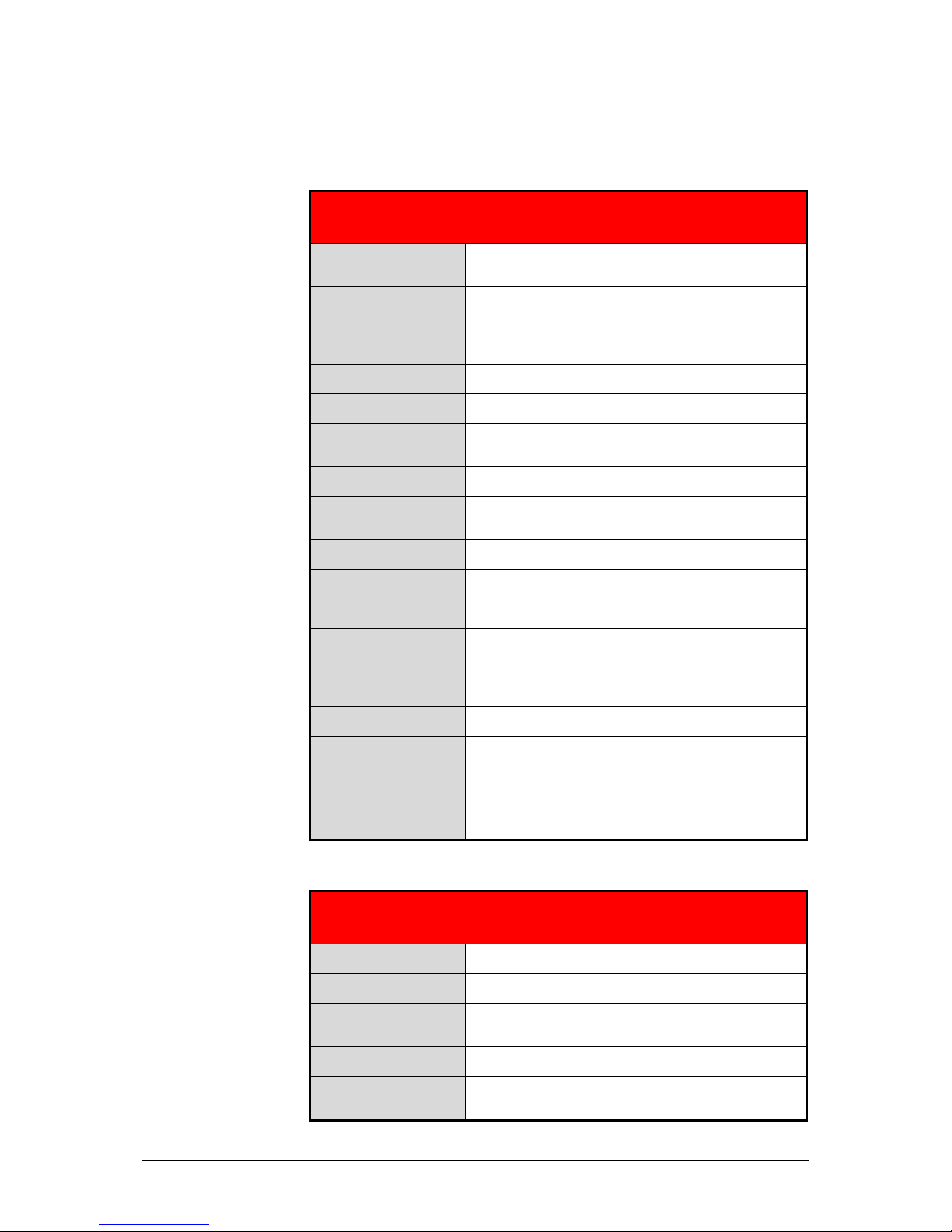
SONAPHONE T, Version 2.0
Ultrasonic transmitter
Transmission
frequency
Approx. 40 kHz
Functionality
Adjustable transmission power
Switchable frequency modulation
Auto power-off function
Display
Illuminated LC display
Connections
For various transmitters
Power supply
2 AA batteries or accumulators (optionally via
power supply unit)
Running time
Approx. 100 hours with battery operation
Operating
temperature
-10 °C ... +60 °C
Storage temperature
-20 °C ... +60 °C
Protection type
Device: IP54
Probe: IP20
Dimensions
Without probe: LWH 130 x 85 x 30 mm
With L50 probe: Length ~170 mm
Probe: Length ~ 52 mm, Ø ~ 22 mm
Items supplied
Ultrasonic transmitter, L50 transmitter
Optional
accessories
Laptop carrying bag with foam plastic
Extension for the probes
Power suppl y unit
SONOSPHERE spherical transmitter
Table 6: Technical data for SONAPHO NE T
SONOSPHERE
Half or full spherical transmitter
Dimension
Ø 100 mm
Weight
620 g without accessories
Operating
temperature
-10 °C ... +60 °C
Storage temperature
-20 °C ... +60 °C
Items supplied
Separable spherical transmitter with integrated
connection cable, case, stand, suction cup, magnet
Table 7: Technical data for SONOSPHERE transmitter
 Loading...