

Page 1

SONOTEC
Ultraschallsensorik Halle GmbH
Nauendorfer Straße 2
D-06112 Halle/Saale
Germany
Phone: +49-(0)345 - 13317-0
Fax: +49-(0)345 - 13317-99
http://www.sonotec.de
E-mail: [email protected]
Ultrasonic
Leak Detector and Leakage Tester
SONAPHONE M
Operating instructions
Version 1 Revised: 2011-09-26
Page 2

OM_SPHM_engl_Vers.1_2011-09-26 Seite 2
Table of Contents
1 Safety precautions..................................................4
1.1 General safety precautions for the SONAPHONE M........4
2 Scope of supply ......................................................5
2.1 Summary...........................................................................5
2.2 Arrangement of devices and accessories in the
carrying case.....................................................................6
3 Function description...............................................7
3.1 General information...........................................................7
3.2 SONAPHONE M connections, controls and display
elements............................................................................8
4 Operation.................................................................9
4.1 Insert the batteries ............................................................9
4.2 Starting up the unit..........................................................12
4.3 Battery status indicator....................................................12
4.4 Check mode....................................................................13
4.5 Main menu ......................................................................16
4.6 Data logger......................................................................17
4.7 Test parameters..............................................................24
4.8 Settings...........................................................................27
5 Using the probes...................................................29
5.1 L50 probe for air-borne noise..........................................29
5.2 L51 special probe for structure-borne noise....................30
5.3 L52 probe for steam traps and fittings.............................30
5.4 Probe for continuous testing, abrasion and cavitation
L54..................................................................................31
5.5 L53 flexible probe............................................................32
5.6 Parabolic probe L55........................................................32
6 Using the accessories ..........................................33
6.1 Telescoping rod...............................................................33
6.2 Temperature sensor........................................................34
Page 3

OM_SPHM_engl_Vers.1_2011-09-26 Seite 3
7 PC connection & data transfer.............................35
7.1 Directory structure of the installation CD.........................36
7.2 Installation for Windows XP / Windows Vista..................36
7.3 Installation for Windows 7 ...............................................38
7.4 Power supply via USB.....................................................40
8 Trouble shooting...................................................41
9 Technical specifications.......................................42
10 Warranty ................................................................43
Page 4

OM_SPHM_engl_Vers.1_2011-09-26 Seite 4
1 Safety precautions
1.1 General safety precautions for the SONAPHONE M
(1) The SONAPHONE M is suitable for the use at temperatures
between -10 °C and +60 °C. Store the unit at temperatures between
-20 °C and +60 °C.
(2) Make sure that you have a clear view of the SONAPHONE M and
the probes at any time of operation. Never work with the probes or the
telescoping rod in areas with live parts or areas you do not know
exactly. When locating ultrasonic signals in electrical installations, keep
a sufficient safety distance to prevent electrical flashover.
(3) Always handle the probe for structure-borne noise with care, so that
the probe tip does not cause any injuries. Use the probe carrier bag on
the shoulder strap of the leather bag when carrying it outside the
carrying case or when the probe is not in use.
(4) Use the shoulder strap on stairs, ladders, platforms etc. so that you
have your hands free to brace yourself.
(5) Avoid using the SONAPHONE M in strong electromagnetic fields.
(6) The SONAPHONE M is a testing devic e.
(7) SONOTEC Ultraschallsensorik Halle GmbH offers no warranty for
damages, even for harm to third parties, caused by incorrect handling of
the device.
(8) The SONAPHONE M, the probes and all accessories have a robust
casing. However, they must be protected from mechanical damage and
sharp impacts. Do not use cleansers containing solvents.
Page 5

OM_SPHM_engl_Vers.1_2011-09-26 Seite 5
2 Scope of supply
2.1 Summary
SONAPHONE M tester
Probes
*
• Probe for air-borne noise L50
• Special probe for structure-borne noise L51
• Probe for steam traps and fittings L52
• Probe for continuous testing, abrasion and cavitation L54
• Flexible probe L53
• Parabolic probe L55
Accessories
*
• Temperature sensor
• Soundproof headphones
• Probe extension cord
• Grip with extension cord for the temperature sensor
• Directional tube
• Tip for directional tube
• SONAPHONE T ultrasonic transmitter
• Spherical transmitter SONOSPHERE
• Telescoping rod
• Carrying case
• PC software
• USB cable
• Operating instructions
*) Please do notice, that the scope of delivery varies according to yo ur
order.
Page 6
OM_SPHM_engl_Vers.1_2011-09-26 Seite 6
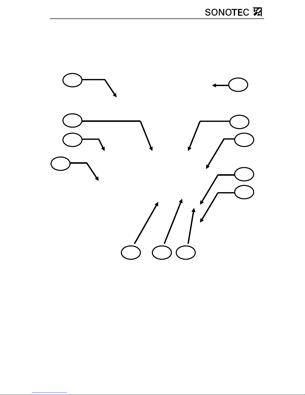
2.2 Arrangement of devices and accessories in the
carrying case
1 Operating instructions
2 Shoulder strap
3 SONAPHONE T
4 Probe for air-borne noise L50
with probe extension cord
5 Recharging power pack for the
SONAPHONE T
6 Probe L52 and 54
7 Headphones
8 Grip with extension cord for
the temperature sensor
9 Special probe for structure-
borne noise L51
10 SONAPHONE M
11 Directional tube and tip for the
tube
12 Temperature sensor
1
3
5
7
4
2
6
8
9
121110
Page 7

OM_SPHM_engl_Vers.1_2011-09-26 Seite 7
3 Function description
3.1 General information
Ultrasound is generated due to friction caused by the flow of gases,
liquids and solids in pipes and leakages. These ultrasonic signals are
recorded by the SONAPHONE M, their intensity is shown on the display
screen and made audible through speakers or headphones. As an
option, surface temperatures can be measured with a temperature
sensor. The recorded data can be stored and transmitted to a personal
computer using the integrated USB interface. Ultrasound can be
generated in a wide variety of processes, for example:
• at leaks in compressed air-, steam- and vacuum systems
• at steam traps
• at leaky valves, gate valves, shut-offs and valves in piping
• from roller bearing damages
• from cavitation at pumps and compressors
• from flashovers and corona discharges on electrical installations
Using the SONAPHONE M, it is possible to locate precisely the defects
and estimate their magnitude. The ultrasonic transmitter
SONAPHONE T can be used to detect leaks in vehicles, freight
containers, other types of containers and ventilation technique systems
where no ultrasound is generated. The SONAPHONE T (optional)
generates ultrasonic waves which emerge at the leaks. Precise location
is carried out from the outside with the SONAPHONE M.
The SONAPHONE M tester is a mobile hand-held and battery-supplied
unit. Various probes, which are connected directly or via a cable to t he
tester, serve to det ect the ult rasound. The type of probe is a utomatically
recognised by the SONAPHONE M by means of a probe code. A
temperature sensor (optional; type K thermocouple, NiCr-Ni) with a
circular plug-in connector is used for temperature readings. It can be
extended at any time using a corr esponding extension cable.
Page 8
OM_SPHM_engl_Vers.1_2011-09-26 Seite 8
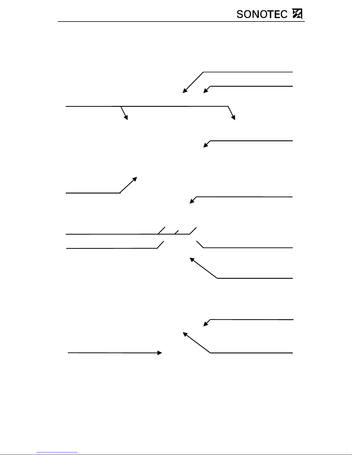
3.2 SONAPHONE M connections, controls and display
elements
Function buttons „F1-F3 “
ON/O
FF
butto
n
USB interface
Ultrasonic-probe connector
Temperature sensor connector
Graphical
display
Fastener for
shoulder strap
Rotary knob with
integrated push button
LIGHT button
Integrated
speaker
Headphone connector
Screw for releasing the
battery compartment lid
Battery compartment lid
Page 9
OM_SPHM_engl_Vers.1_2011-09-26 Seite 9
4 Operation
4.1 Insert the batteries
Safety notes
For operating the SONAPHONE M LR6 batteries with a
nominal voltage of 1,5 V are used.
When opening the battery compartment lid, do not have the
device connected to a PC through a USB cable.
When inserting the batteries, make sure the polarity
corresponds to the engraved marking on the battery block.
Follow the instructions below!
Instructions Description of the battery change
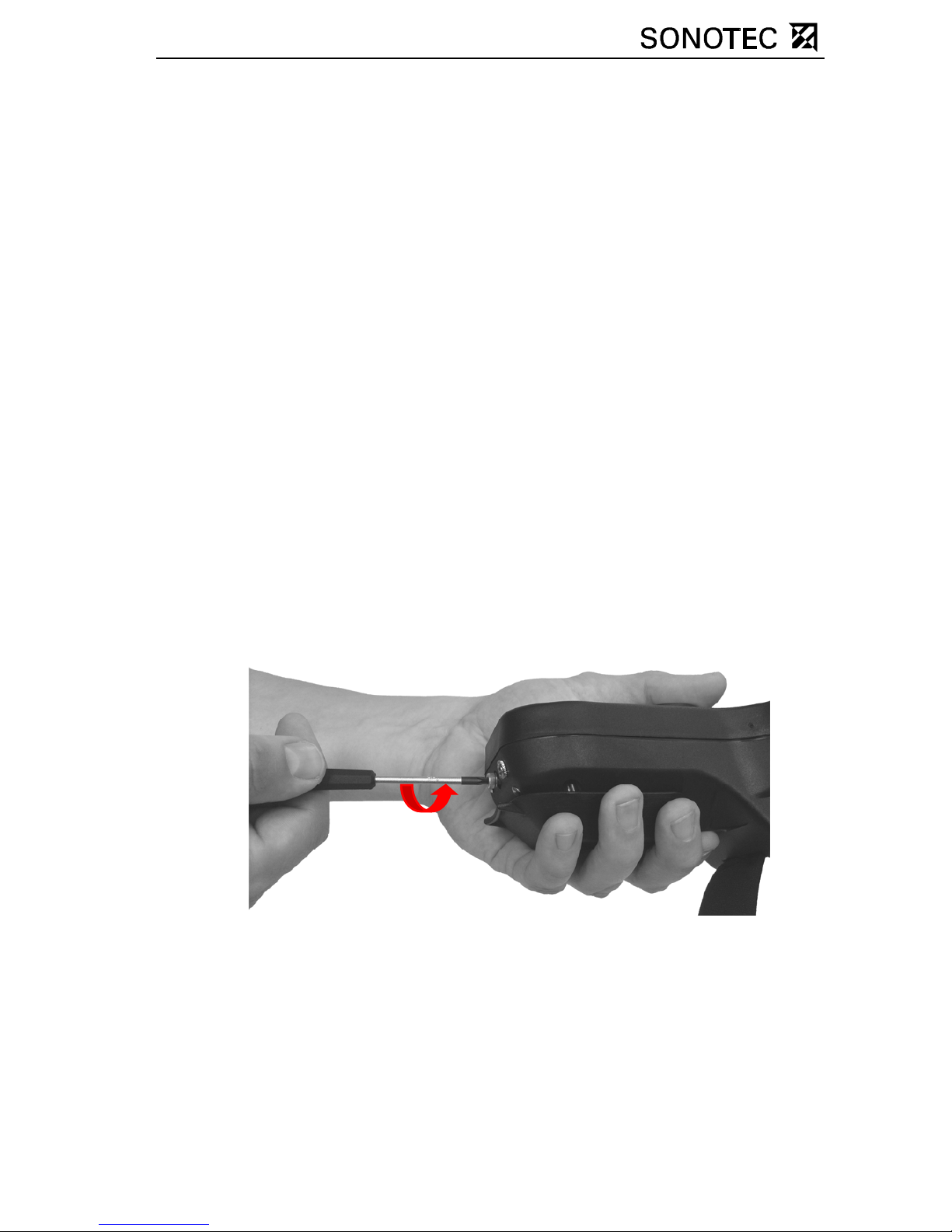
1. Disconnect the shoulder strap from the battery compartment lid.
2. Turn back the locking screw of the battery compartment all the
way until it stops. The battery block will move in the same
direction as the locking screw. It is important to hold the battery
block and the device firmly.
Page 10
OM_SPHM_engl_Vers.1_2011-09-26 Seite 10
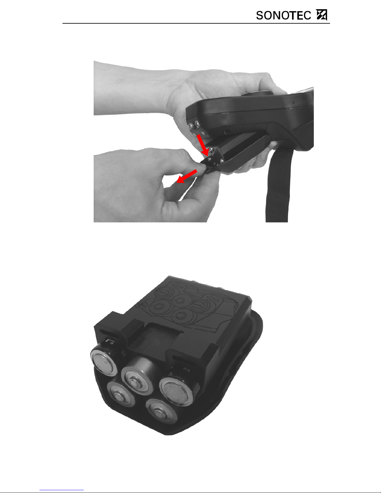
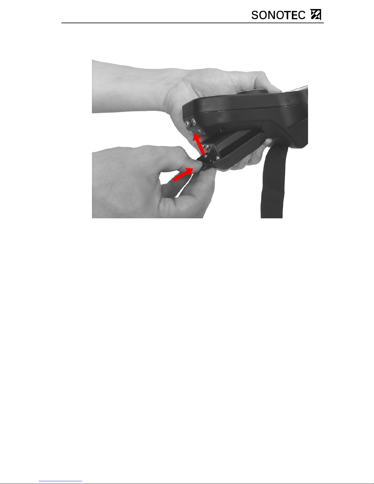
3. Press down the battery compartment and pull it out of the unit
4. Take the batteries out of the battery block.
5. Insert new batteries into the block, checking that the polarity is
correct. An engraving on the top of the battery block illustrates
the correct arrangemen t of the batteries.
Page 11
OM_SPHM_engl_Vers.1_2011-09-26 Seite 11
6. Re-insert the battery compartment into the casing.
7. Tighten the locking screw of the battery compartment again.
8. Fasten the shoulder strap to the battery compartment lid.
Page 12
OM_SPHM_engl_Vers.1_2011-09-26 Seite 12
4.2 Starting up the unit
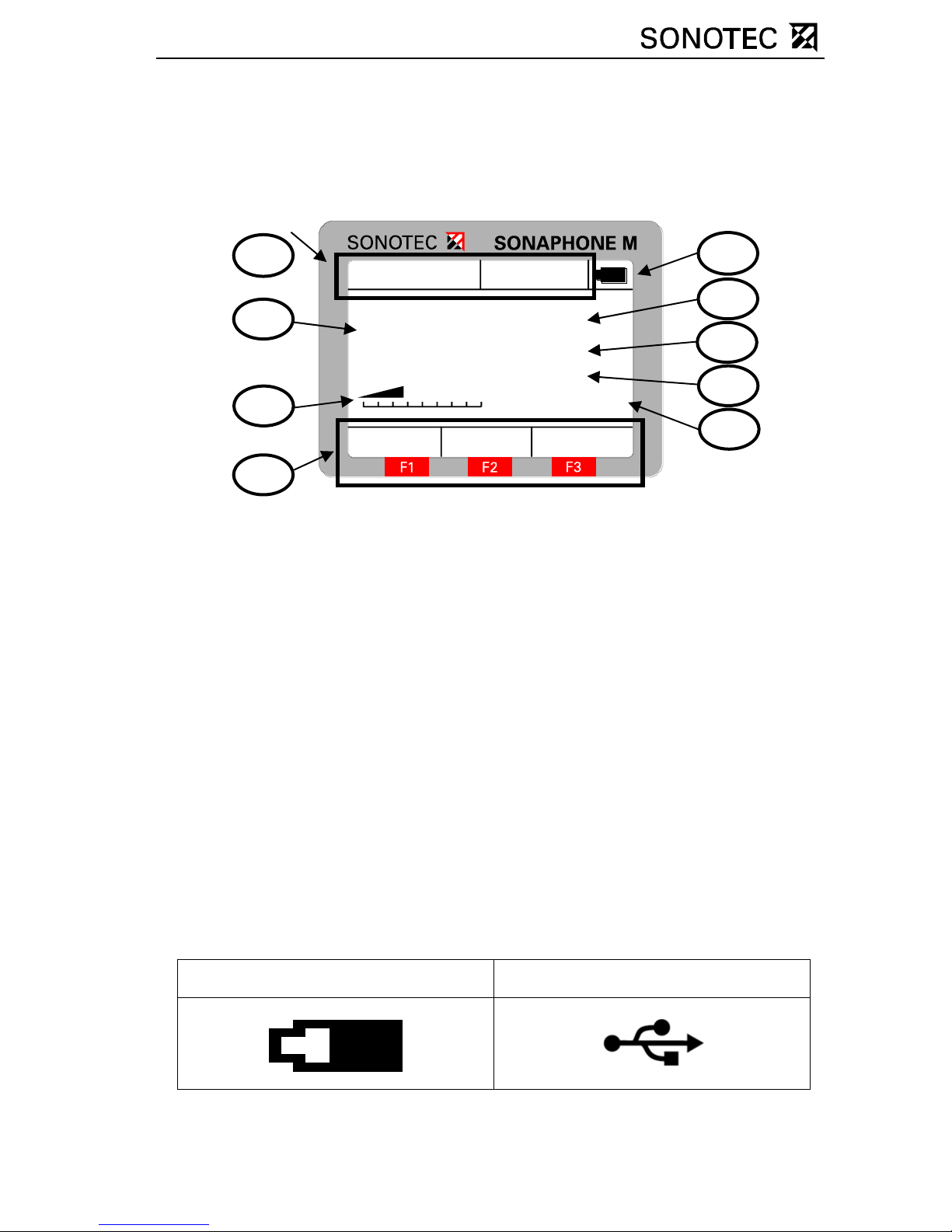
The device is switched on by pressing the ON/OFF button. After
displaying the splash screen, it switches automatically to the testing
mode. The following is shown on the display:
16.02.2007
Max Hold Menu
046
11:24:58
log / 40k Hz
Sensor: L50
Te ster: SO NOTE C
20°C
1 Battery or USB operation
battery status indi c at or
2 Temperature
3 Testin g mo de / m i xer
frequency
4 Type of probe
5 Tester
6 Currently available functions
of keys “F1-F3”
7 Intensity bar for ultrasonic
test values
8 Ultrasonic test values
9 Date / time
4.3 Battery status indicator
The symbol (labelled ’1’ in the above illustration) at the top right edge of
the display provides the user with information about the status of the
batteries in the unit and about the kind of power supply:
Battery operation (about 60%) USB operation
1
9
Page 13

OM_SPHM_engl_Vers.1_2011-09-26 Seite 13
4.4 Check mode
Control elements
Turning the rotary knob: Volume adjustment
Pressing the rotary knob: Storing the test values
(see Section: Single test)
F1 (Max): Turns on or off "Max“ function
F2 (Hold): Turns on or off "Hold“ function
F3 (Menu): Switch to menu in order to adjust the
settings of the unit
“LIGHT“: Controls the display lighting
(Off – Level I – Level II – Level I – Off)
To switch the unit on or off press the ON/OFF button. Depending on the
intended use, connect the appropriate probe or the temperature sensor
to the SONAPHONE M (see Section: Using the probes).
A probe for structure-borne noise is used for locating leaks. The level of
ultrasound is besides the magnitude of the sound source also
dependent on the probe’s direction and distance from the sound source.
This effect can be used to locate and evaluate leaks. If no probe is
plugged into the unit, the message “No Probe” is displayed instead of
the ultrasound level.
Page 14
OM_SPHM_engl_Vers.1_2011-09-26 Seite 14
Volume adjustment
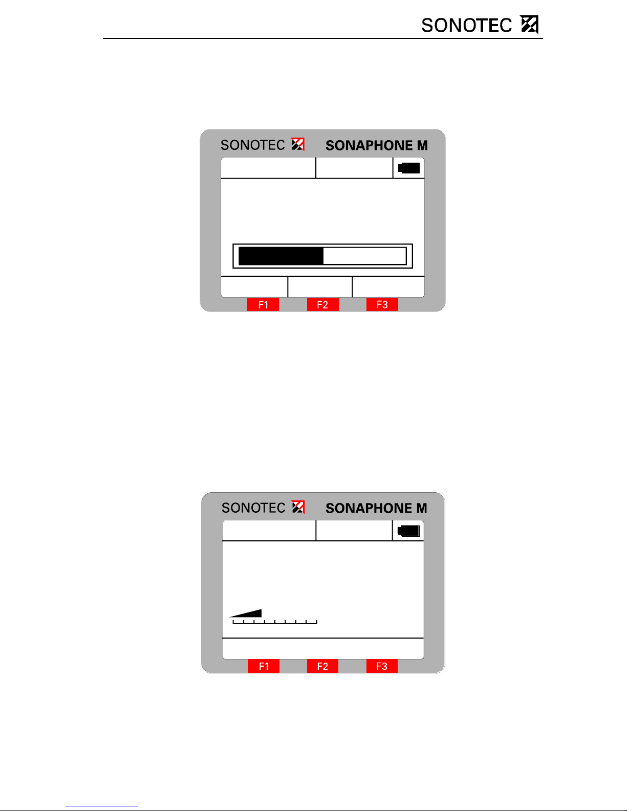
When the rotary knob is turned, a volume bar and an intensity value are
displayed for about two seconds as shown below:
046
16.02.2007 11:24:58
20°C
Volume -24dB
Turning the rotary knob clockwise increases the volume and turning it
anti-clockwise decreases the volume.
Storing the test values
When the rotary knob is pressed in the check mode (provided that at
least one Single test has bee n prepared) , the ult rasonic test values and
the current temperature are stored in the individual test selected as
“Active”. During this process, “Save” and the name of the single test
appear briefly on the display:
16.02.2007
046
11:24:58
log / 40kHz
Sensor: L50
Te ster: S ONOTE C
20°C
Sa ve: Pumpe1
Page 15
OM_SPHM_engl_Vers.1_2011-09-26 Seite 15
"Max“ function
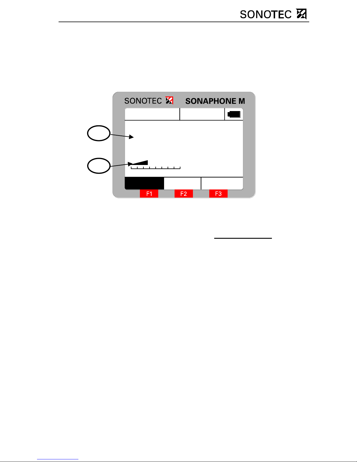
The F1 key activates the “Max” function. In this state, the number
displayed corresponds to the maximum ultrasound level and the
intensity bar to the current ultrasound level. The activation of the “Max”
function is signalled by highlighting the function key description:
16.02.2007
Max Hold Menu
046
11:24:58
log / 40kHz
Sen sor: L 50
Te ster: S O N OTE C
20°C
1 Maximum ultrasound level
2 Current ultrasound level
Pressing the rotary knob stores the currently displayed value
, in other
words the maximum value, in the individual test that is active.
Press the „F1” function key again to deactivate the “M ax” function.
Page 16
OM_SPHM_engl_Vers.1_2011-09-26 Seite 16
"Hold“ function
Press the F2 function key to activate the “Hold” function. This serves to
register ultrasound levels if the display is, for example, not visible at the
moment of testing. The ultrasound level in the display is stored which
was recorded at the moment the F2 key was pressed.
16.02.2007
Max Hold Menu
046
11:24:58
log / 40kHz
Sen sor: L50
Te ster: S O NOTE C
20°C
Press the rotary knob to store the currently displayed value
, in other
words the “Hold” value, in the individual test that is active.
Press the F2 key again to deactivate the “Hold” function.
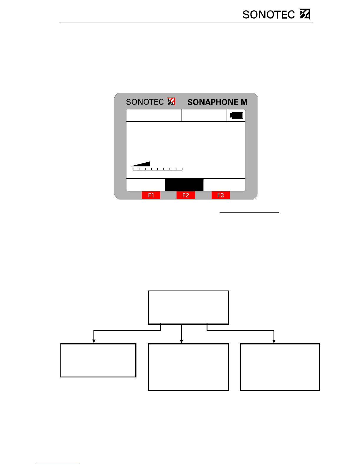
4.5 Main menu
Menu structure
Data Logger (1)
Test Parameter (2)
Setup (3)
Single Test (1) Averaging time (1) Date/Time (1)
Tester (2) Auto-Power-Off (2)
Long-time test (2) Mixer Frequency (3) Auto-Light-Off (3)
Mode (4) Contrast (4)
Temperature (5) Language (5)
Page 17
OM_SPHM_engl_Vers.1_2011-09-26 Seite 17
Operation
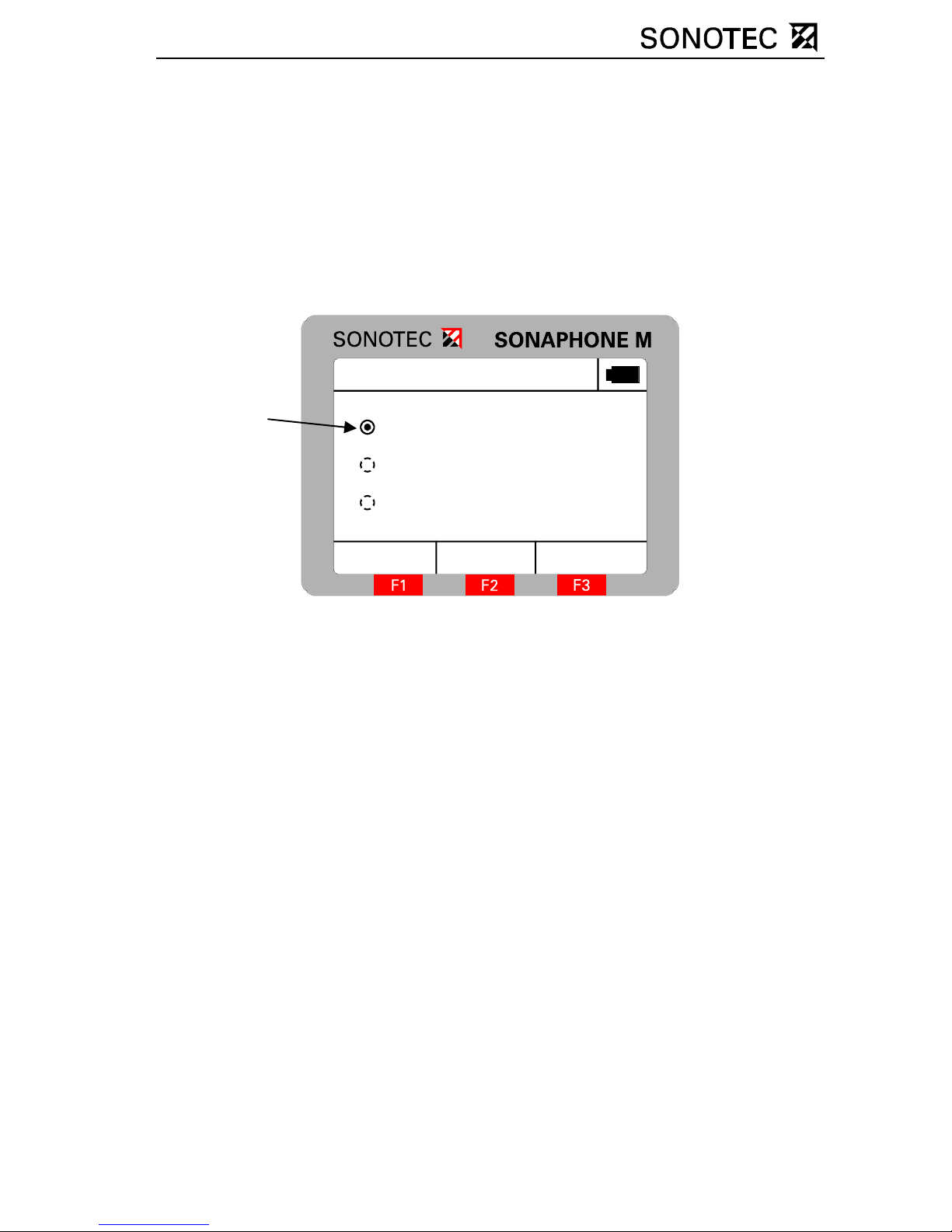
There is a choice of three menu items in the main menu: the data logger
for storing the test values, the test parameters for changing all
parameters relevant to the test and the setup for changing the device’s
parameters. The selection is carried out by turning the rotary knob.
Press it to open the respective menu. Press the F3 function key to
return the unit to the check mode.
The selected menu item is ind ic ated by a dot in the selection circle.
Menu
ESC
Data Logger
Test Parameter
Setup
4.6 Data logger
General information
Ultrasound levels and temperature test values can be stored in the data
logger. The data record includes the date, the tester (maximum eight
characters), the test site (maximum 16 characters), the type of probe
used, the ultrasound level and the temperature. There are two kinds of
tests:
1. Long-time test: Storing ultrasonic and temperature test values
over a longer period at constant time intervals.
A maximum of 250 Long-time tests with
73 datasets each, or 1 Long-time test with
20,000 datasets can be recorded. 1 record
consists of the ultrasonic test value and the
temperature test valu e.
Selection
Page 18
OM_SPHM_engl_Vers.1_2011-09-26 Seite 18
2. Single test: Storing current ultrasonic and temperature test
values in one file.
A maximum of 250 individual tests with
25 datasets each, or 1 individual test with
6,000 datasets can be recorded.
Use the PC software SONAPHONE Communicator, available as an
accessory, for archiving the measurement data.
Long-time test
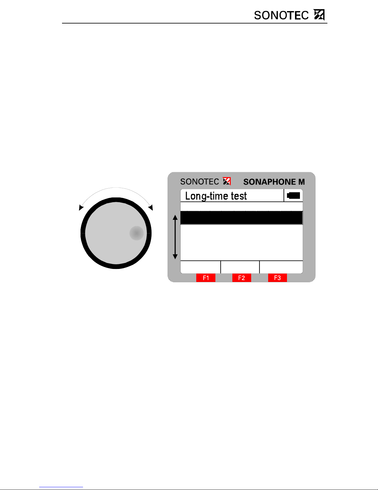
Once the Long -time t est has been selected, a sum mary of a ll Long-ti me
tests created until then appears, showing the respective test site and the
date of creation:
In this menu, the user has a choice of four options:
Pressing the rotary knob: Detailed information about the selected
Long-time test
F1 (Return): Return to the Data Logger menu
F2 (New): Create a new Long-time test
F3 (Selection): Record test values for the selected
Long-time test
Selection
Back
Name
Halle 2
Pumpe
Motor1
New
Halle 1
Page 19
OM_SPHM_engl_Vers.1_2011-09-26 Seite 19
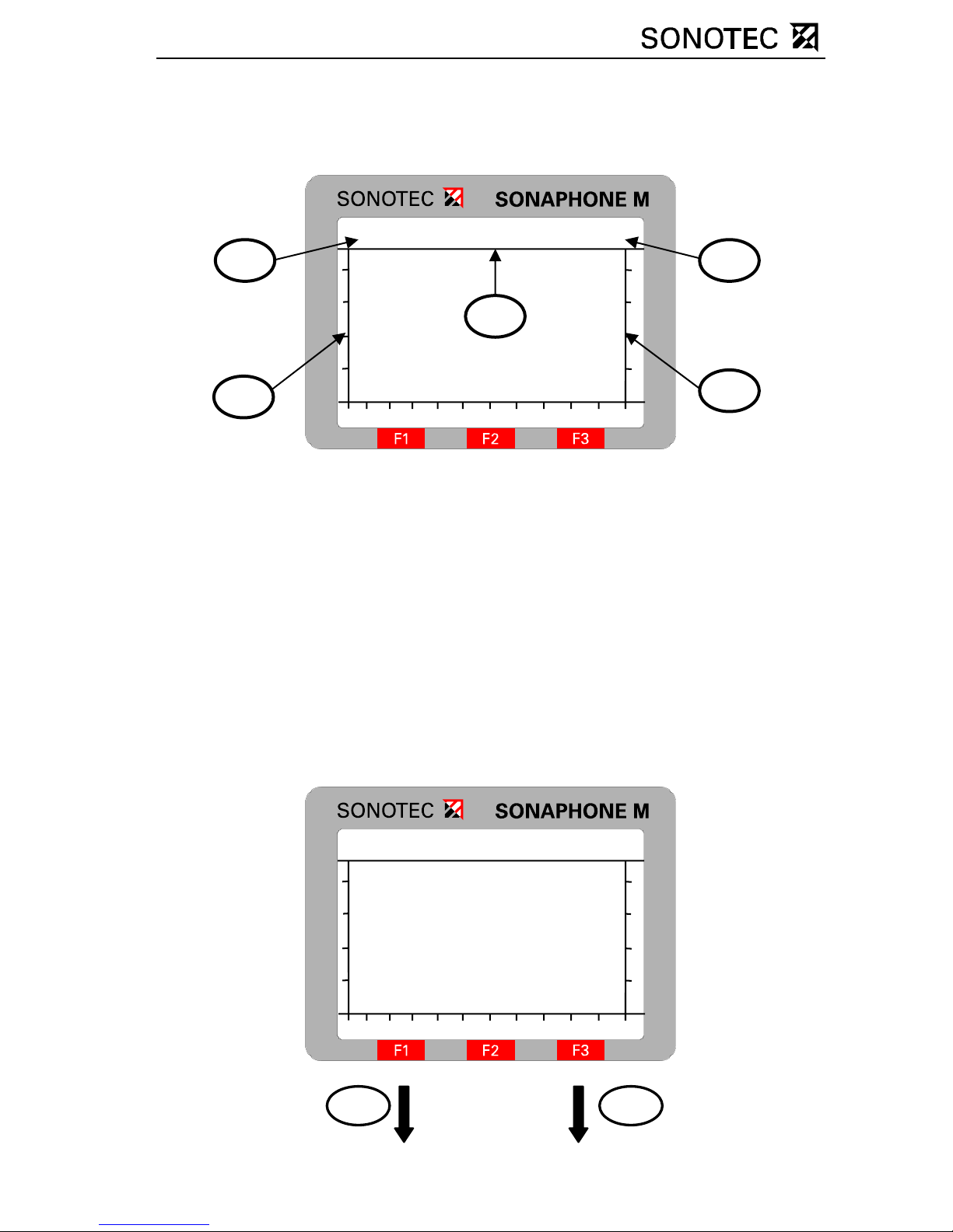
1. Create new Long-time test
To create a new Long-time test, press function key F2 to open a new
screen:
Test Parameter SetupStar t
037 00:00:30 17°C
1 Ultrasonic test value
2 Test duration
3 Temperature
4 Scale for the ultrasonic test value
5 Scale for the temperature test
value
To set the testing parameters, open the parameter menu using the
function key “F1”. In order to make adjustments to the display of the
Long-time test, or to end the Long-time test, the menu item “setup” has
to be opened by pressing function key “F3”:
Test Parameter SetupStar t
037 00:00:30 17°C
3 1
2
4
5
Page 20
OM_SPHM_engl_Vers.1_2011-09-26 Seite 20
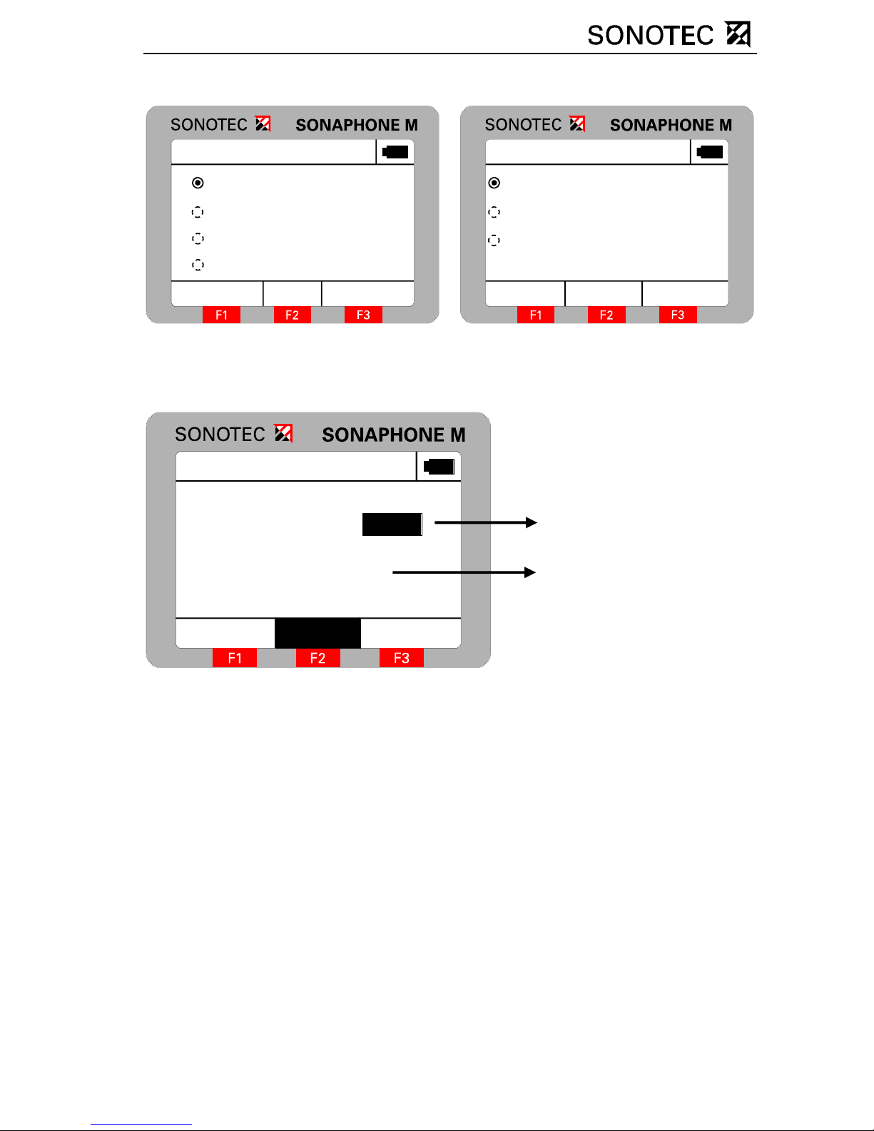
Test Parameter
Start
Test place / Tester
Start
Create
Duration
Interval
ESC
Setup
Back
max. Temperature
max. Ultrasound
Close LTT!
100°C
14 0
See section Setting the tester for instructions on setting the test place
and tester. In the start menu, the user can set the type and starting time
of the Long-time test:
Long- time test - St art
Back
Date
Time
17.04.
10:39:00
AutoManually
2007
When this menu is opened, the start of the Long-time test is set to
“Auto”. The SONAPHONE M will thus start the Long-time test
automatically at the time that has been set. If the time entere d is earlier
than the present time, the test is started immediately. Switching to
“manual” enables to start the Long-time test manually. Select the
element to be edited by pressing the rotary knob. archiving can be made
by turning the rotary knob. Press function key F3 to store the starting
time for the selected Long-time test.
The scaling of the ultr asonic and temperature read ings depends on the
limits for maximum temperature and maximum ultrasonic level which
have been set under setup.
dd.mm.yyyy
hh.mm.ss
Page 21
OM_SPHM_engl_Vers.1_2011-09-26 Seite 21
2. Start Long-time test
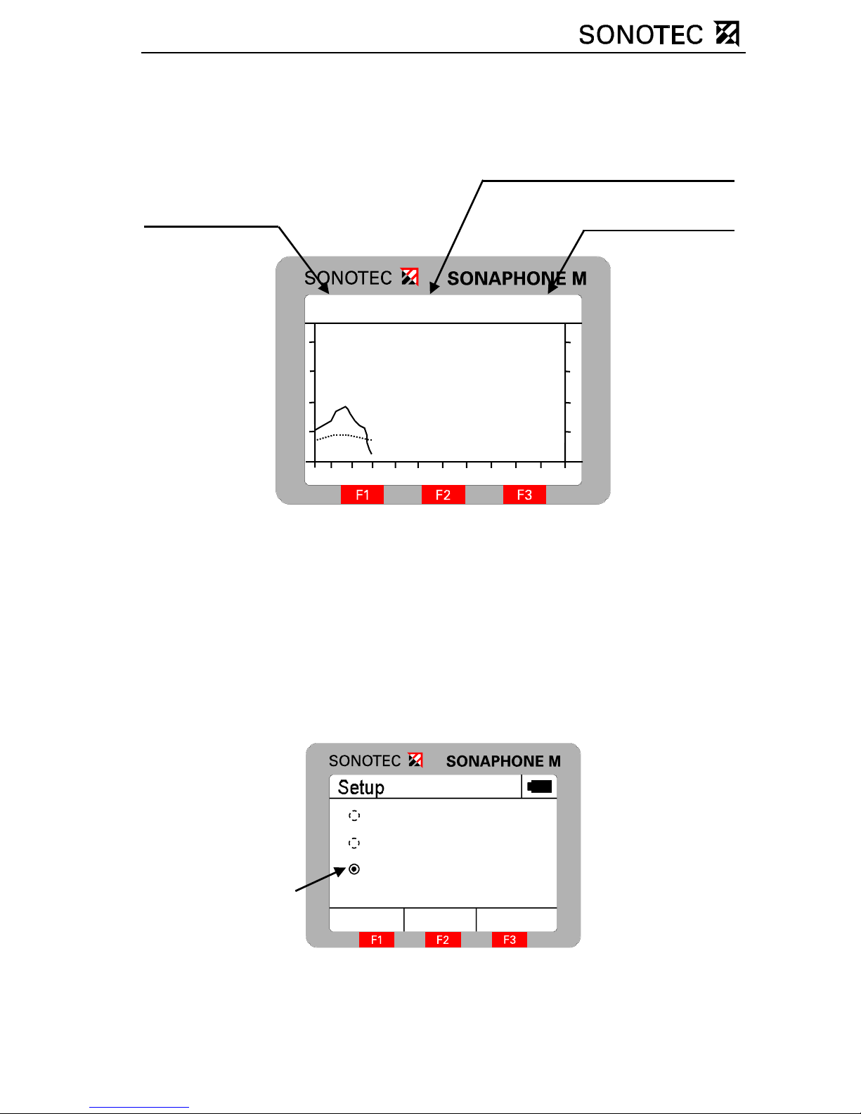
The Long-time test can be manually started in the measuring screen by
pressing function key F2:
Remaining testing time
Stop
037 00:00:14 17°C
The ultrasonic readings are represented by a solid line, and the
temperature readings by a dotted line. The remain ing time of the test is
shown at the top centre of the screen. The Long-time test can be
cancelled at any time by pressing function key F2. The values recorded
up to that time are stored and the entry for the duration of the test is
updated.
3. Finishing the Long-time test
To exit the Long-time recording and to return to the check mode choose
“Close LTT!“ in the menu s e tup.
Back
Max.Temperature
Max. Ultrasound
Close LTT!
100°C
140
All test values, which have been recorded until this point, are kept and
displayed in the diagram of the Long-time tests stored in the device.
Ultrasonic
test values
Temperature
test values
Page 22
OM_SPHM_engl_Vers.1_2011-09-26 Seite 22
4. Details of the selected Long-time test
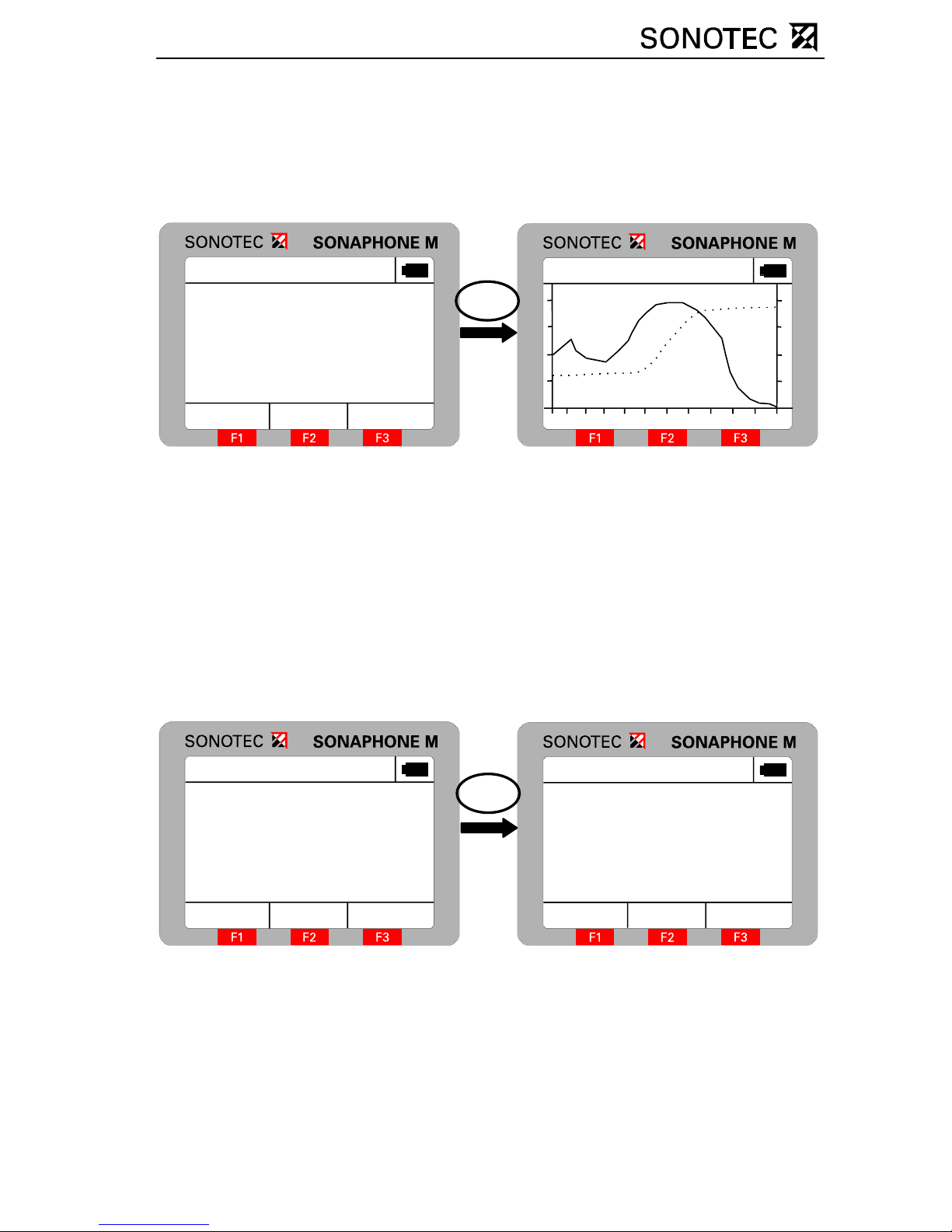
In the following, information about tester, testing site, date, time,
duration and intervals of the test is given. Now, you have the option of
deleting the progressive test or viewing the test values in form of a
diagram.
L o n g -time te s t In fo
ShowBack
Test place
Motor 1
Date
Time
Duration
SONOTEC
05.03.07
14:17:03
00:01:00
Delete
Tester
:
:
:
:
:
L o n g -time te s t In fo
Back
ESC
Ultrasonic test values are represented by a solid line and temperature
values by a dotted line. The visible time period is a maximum of 60
seconds. If the duration of the test is longer than 60 seconds, it is
possible to shift the window of time by turning the rotary knob. The
ultrasonic test values are shown over a range of 0-140 scale divisions
for the logarithmic scaling, and 0-240 divisions for the linear scaling. The
temperature is shown over the range 0 … 800 °C or 0 … 1472 °F.
Press function key F2 in the detail screen to delete the current data
record. As a safety measure, you are asked if this record should
definitively be deleted:
L o n g -time te s t In fo
ShowBack
Test place
Motor 1
Date
Time
Duration
SONOTEC
05.03.07
14:17:03
00:01:00
Delete
Tester
:
:
:
:
:
Delete dataset
YESNO
Ar e th es e Data
to be deleted?
To confirm, press function key F3, to cancel this action press F1.
Page 23
OM_SPHM_engl_Vers.1_2011-09-26 Seite 23
5. Start/overwrite Long-time test selected
The last item of the Long-time test menu, gives you the option of starting
a Long-time test that is already parameterised, or overwriting an existing
Long-time test. This is done by pressing function key F3.
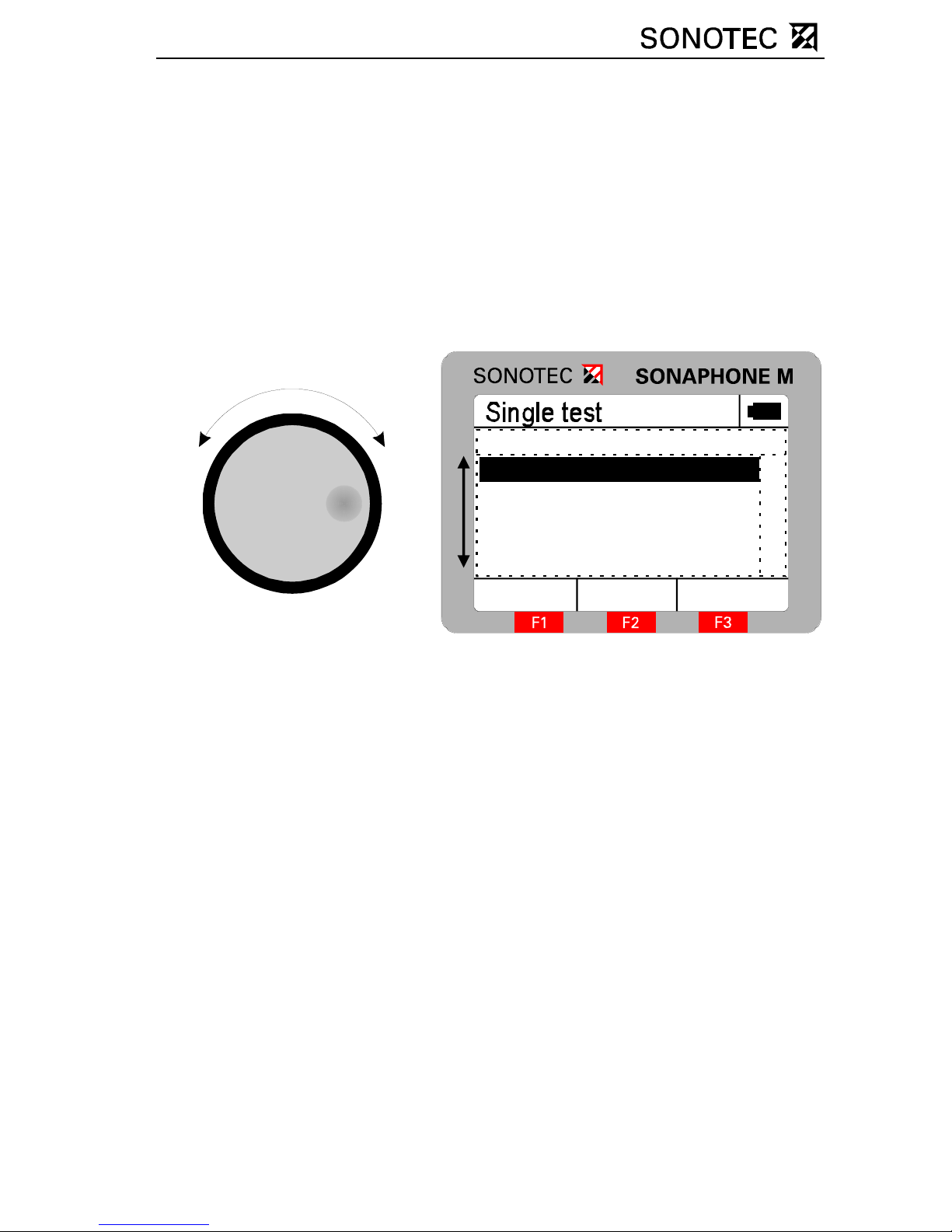
Single test
Once the individual test has been selected, a summary of all individual
tests created previously, with their respective testing sites and
corresponding status, appears. The test data, that has to be stored, is
filed in the Single test marked “active”.
Selection
Name
NewBack
Motor1
Motor2
Halle2
Halle1
A
By pressing function key “F2” you can create a new Single test, by
turning the rotary knob you can edit the current Single test, and you are
able to activate the selected Single test by pressing “F3”.
The result of activating a Single test is that the test values are stored in
this individual test within the test mode. Only one Single test at a time
can have the “active” status; it is not possible to activate more than one
Single test simultaneously. A Single test is edited or created in the
following menu:
Page 24
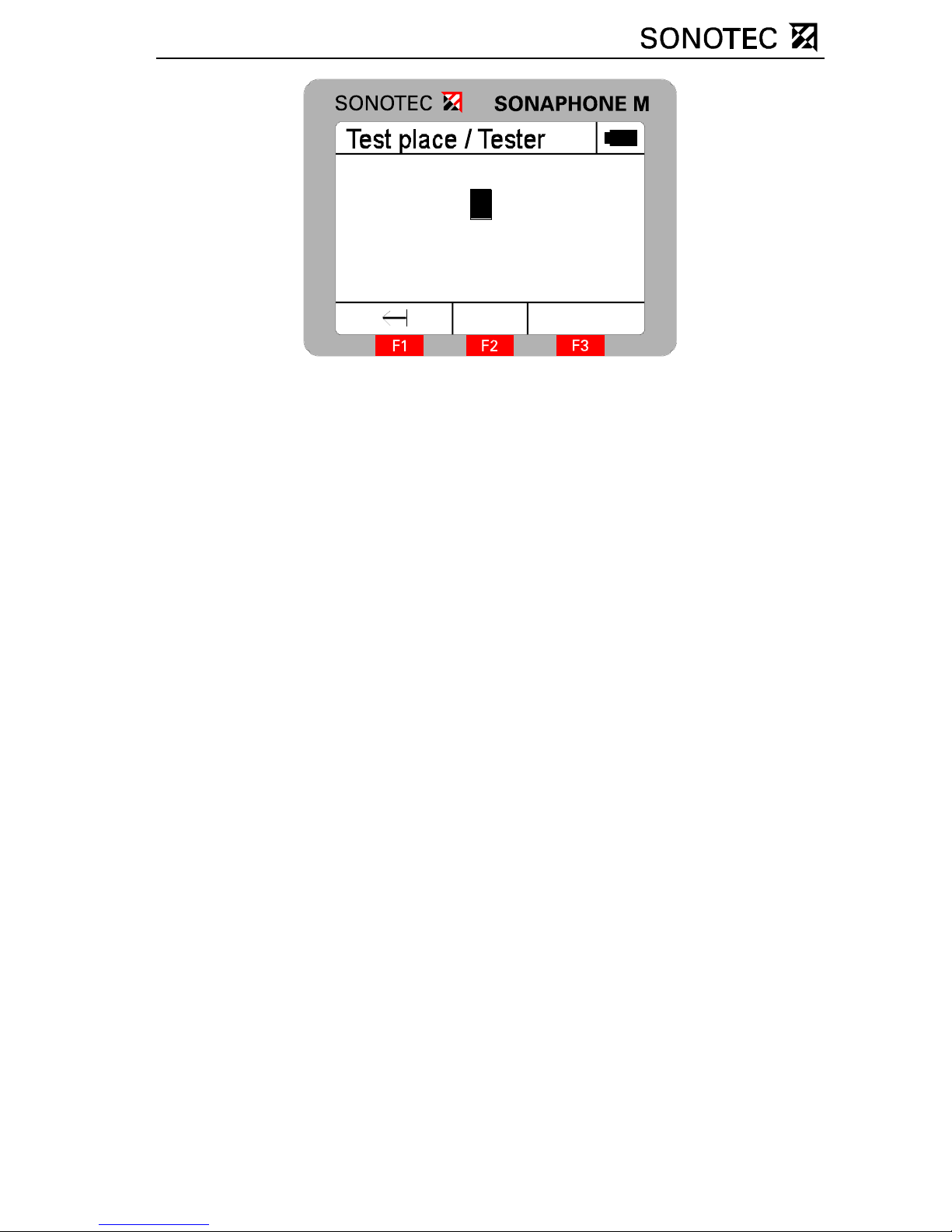
OM_SPHM_engl_Vers.1_2011-09-26 Seite 24
Save
Test place
Tester
MOTOR
SONOTEC
1
012
The character to be edited is selected by pressing the rotary knob and
set by turning it. To edit the last character again press the Button “F1”.
Press “F3” to store both the tester’s name and the test site for the
corresponding Single test.
The test values are stored in the test mode by pressing the rotary knob.
The following data is stor ed for each test:
- Date / time
- Type of probe
- Test mode / mixer frequency
- Ultrasonic test value
- Temperature value
Archiving the individual tests is only possible by using the PC software
SONAPHONE Communicator, available as an accessory tool.
4.7 Test parameters
Note
Altering all test parameters has a direct influence on the test values
displayed. In order to ensure reproducibility, tests which have to be
compared must be recorded with identical test parameters.
Page 25
OM_SPHM_engl_Vers.1_2011-09-26 Seite 25
Device reset
Entering key „F1“ when the splash screen is displayed rests all test
parameters to the delivery status.
Averaging time: 4 s
Tester: SONOTEC
Mixer frequency: 40 kHz
Check mode: logarithmic
Temperature: °C
Notice: The test vales stored in the device are not affected by the
device reset. Only the test parameters are r eset to the initial settings!
Setting the averaging time
The SONAPHONE M provides the option of averaging the test values
recorded over a variable period. The period is set between 0 and 10
seconds in half second increments in the averaging time menu. By
turning the rotary knob the settings can be changed and stored in the
device. By pressing of „F1“ you can reach the menu test parameters
and by pressing „F3“ you can leave the settings and return to the test
monitor.
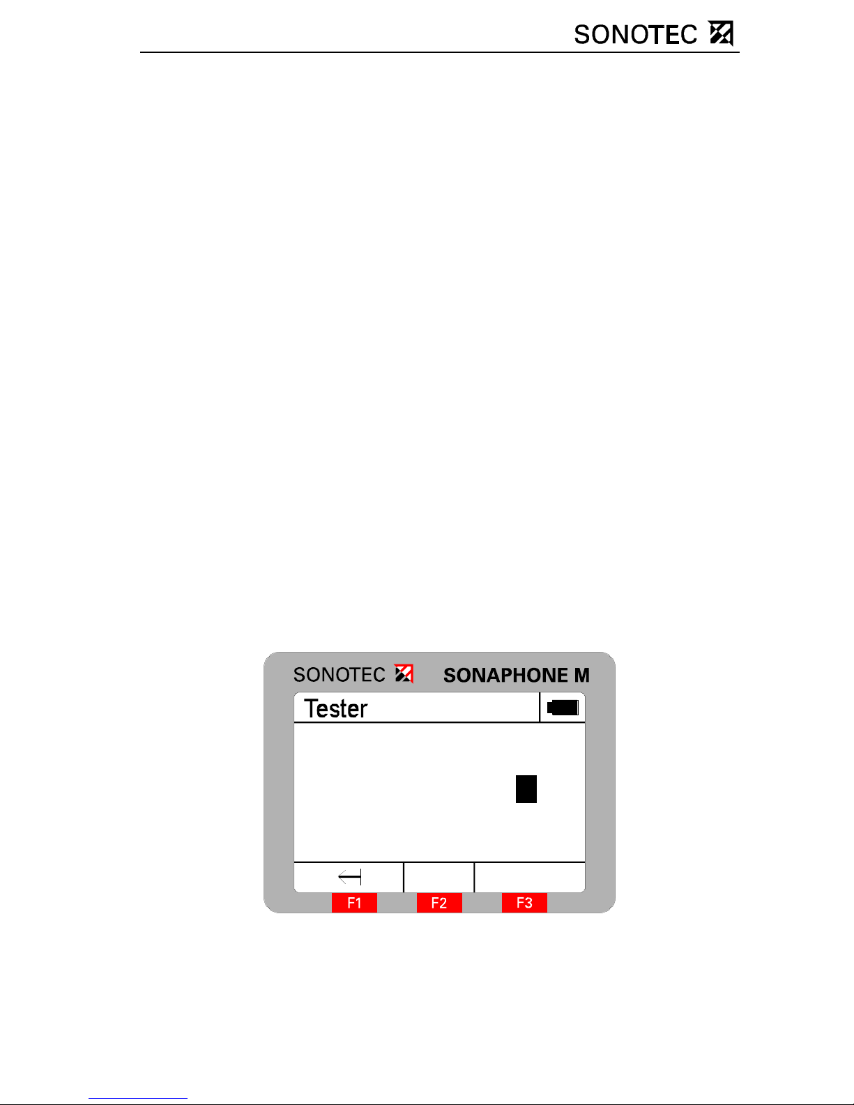
Setting the tester
In this menu, you have the option of entering 8-character-long
designations for the tester. To switch between character sets (ABC
abc
012 :;<), press function key “F2”.
Save
Tester
SONOTE
1
012
C
The character to be edited, is selected by pressing the rotary knob and
set by turning it. Press “F3” to store both the tester’s name and the test
site in the device.
Page 26

OM_SPHM_engl_Vers.1_2011-09-26 Seite 26
Setting the mixer frequency
In the SONAPHONE M, ultrasound is transformed into audible sound by
a frequency conversion process. The unit provides the option of setting
the working frequency via the mixer frequency. The frequency range
can be set between 20 and 60 kHz, in increments of 2 kHz. The default
value is 40 kHz. By turning the rotary know setting can be changed and
saved in the device. Press function key “F1” to return to the previous
menu and F3 return to the test mode.
Notice: Changing the mixer frequency makes only sense when using
the probes L52 or L54, since these probes have the necessary
bandwidth.
Setting the test mode
The SONAPHONE M has two different display modes for the ultrasonic
test value, the linear mode (linear scale 0 - 240) and the logarithmic
mode (logarithmic scale 0 - 140). This can be set in the mode menu.
The element to be edited is selected by pressing the rotary knob, and
set by turning it. Press function key “F1” to return to the previous menu
and F3 return to the test mode.
Setting the temperature display
The SONAPHONE M provides the option of showing the temperature in
°C or in °F. The switch over between the two types of display can be
done in this menu. The element to be edited is selected by pressing the
rotary knob, and set by turning it. Press function key “F1” to return to the
previous menu and F3 return to the test mode.
Page 27
OM_SPHM_engl_Vers.1_2011-09-26 Seite 27
4.8 Settings
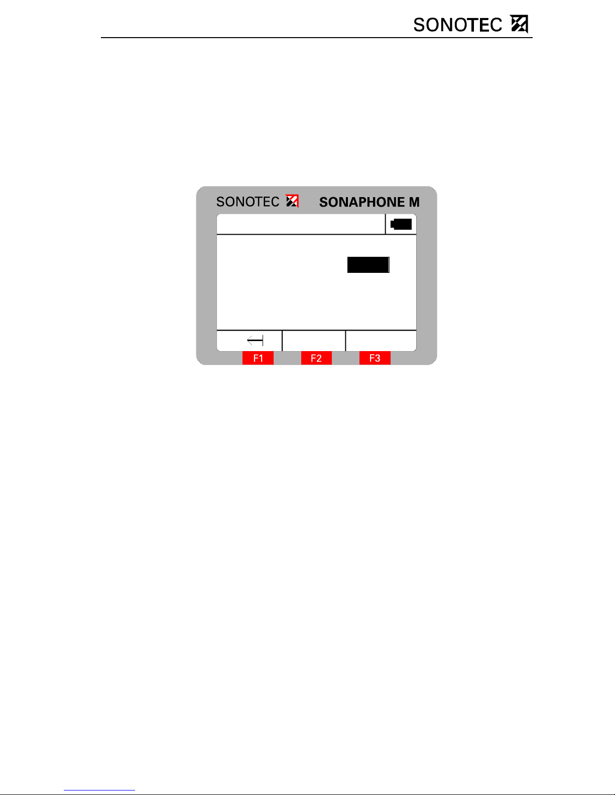
Date/Time
In this menu item, the date and time of day are set. You ca n select the
desired element by pressing the rotary knob and set the desired value
by turning it. It is not possible to set the seconds. These are reset to “00”
when the menu is opened.
Date/Time
Date
Time
17.04.
10:39:00
Auto
Save
2007
Back
The element to be edited is selected by pressing the rotary knob, and
set by turning it. To edit the last element again press function key “F1”.
Pressing function key “F2” stores the time. Pressing function key “F3”
deletes the settings and returns the unit to the previous menu.
Auto Power Off
The Auto–Power Off function allows the SONAPHONE M to be switched
off automatically after a set length of time. Times between 1 and 25
minutes can be set in one minute increments. Press function key “F1” to
return to the previous me nu and F3 return to the test mode.
Auto Light Off
The Auto Light Off function allows the display background lighting to be
switched off automatically after a set length of time. Times between 0
and 2 minutes can be set in 30 second increments by turning the rotary
knob. Press function key “F1” to return to the previous menu and “F3”
return to the test mode.
Page 28

OM_SPHM_engl_Vers.1_2011-09-26 Seite 28
Contrast
In order to adjust the readability of the display to the particular
conditions it may be necessary to adjust the contrast. This can be done
in the contrast menu by turning the rotary knob. The changes take effect
immediately on the screen.
Language
The menu prompts on the SONAPHONE M can be either in German or
in English. This is set in the language menu by turning the rotary knob.
Press function key “F1” to return to the previous menu and “F3” to return
to the test mode.
Page 29

OM_SPHM_engl_Vers.1_2011-09-26 Seite 29
5 Using the probes
5.1 L50 probe for air-borne noise
The L50 probe for air-borne noise serves for general detection of
ultrasound.
The precision of location is increased by mounting the directional tube.
For precise fault location mount the tip onto the directional tube as well.
If the fault cannot be located with the probe mounted directly on the
SONAPHONE M, a special extension cable can be used.
directional tube
directional tip
Page 30

OM_SPHM_engl_Vers.1_2011-09-26 Seite 30
5.2 L51 special probe for structure-borne noise
The L51 special probe for structure-borne ultrasonic noise is especially
suitable for locating sources of ultrasound on flat surfaces.
Since the special probe for structure-borne noise is watertight, it can
also be used for ultrasonic inspections in moist environments or in water
systems. After the use, the probe must be dried.
5.3 L52 probe for steam traps and fittings
The probe for steam traps and fittings is used to detect ultrasound in
solid objects and rotat i ng mach in er y .
Page 31
OM_SPHM_engl_Vers.1_2011-09-26 Seite 31
It has to be pressed gently by hand against the spot that has to be
examined. In order to achieve reproducible results, the contact pressure
and direction must be kept constant. The probe can be operated in a
temperature range of -20 °C … +60 °C. Short-term measurements (ca.
1 minute) at hot surfaces are possible until 550 °C.
Notice: For optimising the test procedure the mixer frequency of the
device can be diversified (section 4.7) between 20 and 60 kHz in 2 kHz
increments. Changing the mixer frequency does not effect the shown
test values directly. In order to ensure reproducibility, values that have
to be compared must be recorded with identical mixer freq uencies.
CAUTION!
When using probe L52, observe item 3 of the general safety
precautions.
5.4 Probe for continuous testing, abrasion and cavitation
L54
Probe L54 is used for the detection of ultrasound in solid objects and
rotating machinery. For continuous testing the probe is fixed to the test
object.
Page 32
OM_SPHM_engl_Vers.1_2011-09-26 Seite 32
It has to be pressed gently by hand against the spot that has to be
examined. In order to achieve reproducible results, the contact pressure
and direction must be kept constant. The probe can be operated in a
temperature range of -20°C … +60°C. Short-term measurements (ca.
1 minute) at hot surfaces are possible until 550°C.
Notice: For optimising the test procedure the mixer frequency of the
device can be diversified (section 4.7) between 20 and 60 kHz in 2 kHz
increments. Changing the mixer frequency does not effect the shown
test values directly. In order to ensure reproducibility, values that have
to be compared must be recorded with identical mixer freq uencies.
CAUTION!
When using probe L54 probe, observe item 3 of the general safety
precautions.
5.5 L53 flexible probe
The flexible probe for air-borne noise serves to detect ultrasound at
areas that are particularly difficult to reach.
CAUTION!
When using the L53 flexible probe, observe Item 2 of the general safety
precautions.
5.6 Parabolic probe L55
The parabolic probe L55 serves to detect ultrasound at areas that are
particularly difficult to reach.
Page 33
OM_SPHM_engl_Vers.1_2011-09-26 Seite 33
6 Using the accessories
6.1 Telescoping rod
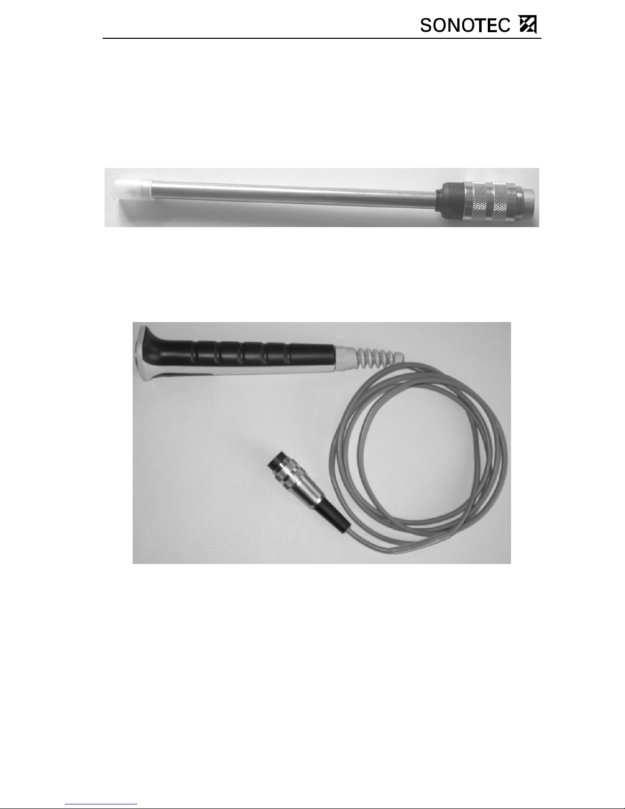
The telescoping rod increases the reach when handling the probes. To
use it, clamp the probes in the rotatable clamp and connect the plug
connector near the clamp. The telescoping rod is connected by cable to
the SONAPHONE M. The length of the telescoping rod is continuously
adjustable from about 1.7 metres to about 3 metres. To do this, loosen
the black coupling ring between the inner and outer tubes of the
telescoping rod. When contracting the telescoping rod, carefully draw
the cable out of the outer tube.
CAUTION!
When using the telescoping rod, observe item 2 of the general safety
precautions.
Page 34
OM_SPHM_engl_Vers.1_2011-09-26 Seite 34
6.2 Temperature sensor
Temperatures between 0 °C and 800 °C can be measured using the
temperature sensor.
The temperature sensor can either be plugged into the SONAPHONE M
directly or by using a grip together with the extension cable.
If no temperat ure sensor is plugged in, (---) will be shown on the display.
Page 35

OM_SPHM_engl_Vers.1_2011-09-26 Seite 35
7 PC connection & data transfer
CAUTION!
The SONAPHONE M should only be connected to a PC if the battery
compartment lid is closed! Opening the battery-compartment lid while
the unit is connected to the PC can result in damage to the unit!
The SONAPHONE M can be connected to a computer using a USB
cable. SONAPHONE Communicator software is needed in order for the
device to communicate with the computer. This contains all the
necessary drivers to log the SONAPHONE M into the operating system
and to ensure a power supply to the unit through the PC. It is not
possible to operate it on a PC without these drivers. The SONAPHONE
Communicator provides the following functions:
- Reading out and managing Single test s
- Pre-parameterising Single tests
- Reading out and managing Long-time tests
- Pre-parameterising Long-time tests
- Archiving test data
- Performing online tests
- Parameterising the device
- Memory management
The installation program for the SONAPHONE Communicator
software starts automatically when the installation CD is inserted
in the drive. If this does not happen, start the program SETUP.EXE
on the installation CD manually. Then follow the instructions that
appear on your computer screen.
Page 36
OM_SPHM_engl_Vers.1_2011-09-26 Seite 36
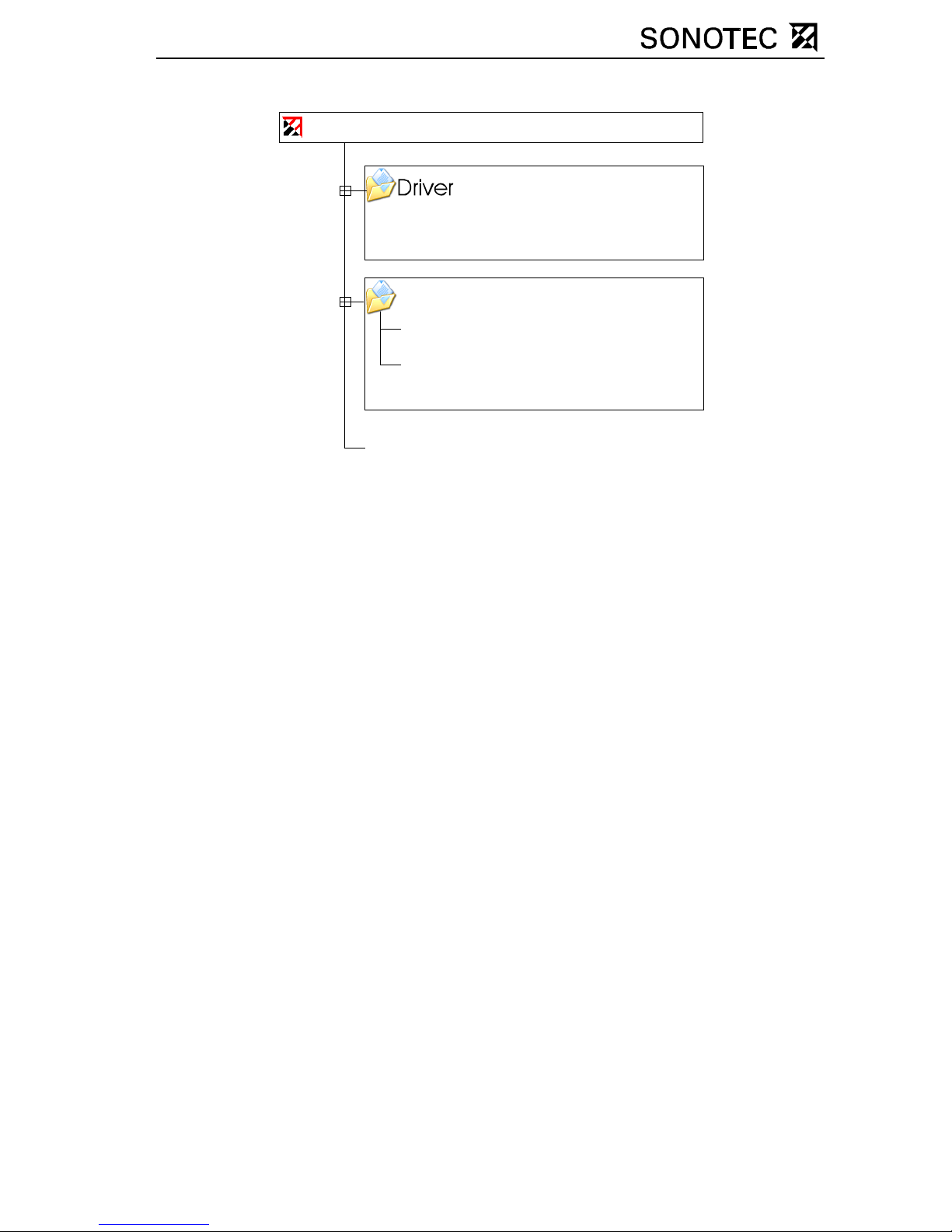
7.1 Directory structure of the installation CD
Operating_manual
Windows X P drivers for the SONAPHONE
Bedienungsanleitung.pdf
Operating_manual.pdf
(german operating manual)
(english operating manual)
Setup-CD
Setup.exe
7.2 Installation for Windows XP / Windows Vista
Installation of the driver unit
When connecting the SONAPHONE M with the PC for the first time, a
dialog for the installation of the driver unit opens:
Step 1:
Windows Update
In this window, choose the
option: „No, not this time“.
Pressing the key „Next >“
leads to the next installation
step.
Page 37

OM_SPHM_engl_Vers.1_2011-09-26 Seite 37
Step 2:
Insert the driver CD
After the insertion of the CD for the
SONAPHONE Communicator the
installation continues automatically. In case it will not work,
press the key „Next >“.
All drivers, which are needed for the operation of the SONAPHONE M,
can be found in the index: „CD-drive:\Driver\“. In case there is no
automatic identification as explained in step 2, you can choose menu
item „Install from a list or specific location“, in order to choose the driver
on the CD manually.
Step 3:
Windows Logo Test
By pressing „Continue Anyway“ all
necessary drivers are installed on
the PC. After successful driver
installation a new window appears,
in which you can finish the
installation by pressing „Finish“.
Installation of the SONAPHONE Communicator
The beginning of the installation programme for the PC-Software
„SONAPHONE Communicator“ happens automatically right after the
insertion of the in stallation CD. In case it will not happen automat ically,
please start the „setup.exe“ on the installation CD manually. Please
follow afterwards the directions on the screen of your PC.
Page 38

OM_SPHM_engl_Vers.1_2011-09-26 Seite 38
7.3 Installation for Windows 7
After the insertion of the installation CD the setup starts automatically. In
the case that the automatic start of the program does not work, the
<setup.exe> has to be started manually from the installation CD. The
following window opens:
By clicking on <Continue> the setup automatically checks if you already
have installed a driver for the SONAPHONE M. If this has not happened
already, the following window opens:
By clicking on <Yes> the installation of th e driver st arts. In th e next step
you has to connect the SONAPHONE M with the Computer via USB
cable. If the device is already connected with the Computer, please
interrupt the connection and connect them again. After connecting the
SONAPHONE M with the Computer, two balloon tips appear on the
status bar.
Page 39

OM_SPHM_engl_Vers.1_2011-09-26 Seite 39
You can ignore these messages or close them by clicking on <X>. Now
you can continue with the driver installation by clicking on <OK>:
The “new hardware wizard” opens. By clicking on “Continue” the driver
installation is performed. The following window opens:
Click on <Install this software anyway> and in the following window on
<Finish>. The driver installation is finished and the setup for the
installation of the SONAPHONE M Communicator will be continued.
Follow the instructions on the monitor.
Page 40

OM_SPHM_engl_Vers.1_2011-09-26 Seite 40
7.4 Power supply via USB
The SONAPHONE M can be supplied (depending on the PC) via
USB interface of the connected PC. If this is not possible, the following
window appears when starting the SONAPHONE Communicator:
You are asked to switch off the SONAPHONE M. Appears a USB
symbol in the upper right corner after having pressed „ON/OFF“, the
switching was successful. Otherwise, you have to press „ON/OFF“ one
more time. If the device will be switched off by pressing „ON/OFF“, there
is no power supply via USB.
Notice: In case the window shown above does not appear after having
started the SONAPHONE Communicator, there is either no
SONAPHONE M connected to the PC or the PC does not supply power
for the SONAPHONE M.
Page 41

OM_SPHM_engl_Vers.1_2011-09-26 Seite 41
8 Trouble shooting
Not every malfunction necessarily involves an actual defect of the
equipment. Time and money can be saved if you are able to correct
simple faults yo urself. The followi ng notes are intended to help do so:
Fault Possible cause Remedy
Device cannot be
switched on
Batteries are empty Insert new batteries
No acoustic signal
detectable
Volume control set too
low
Probe is not connected
properly
Headphones are not
connected properly
Unit switched off
automatically
Defective probe
Adjust volume
Put in the plug
completely
Put in the plug
completely
Switch unit on again
Check with another
probe
Page 42
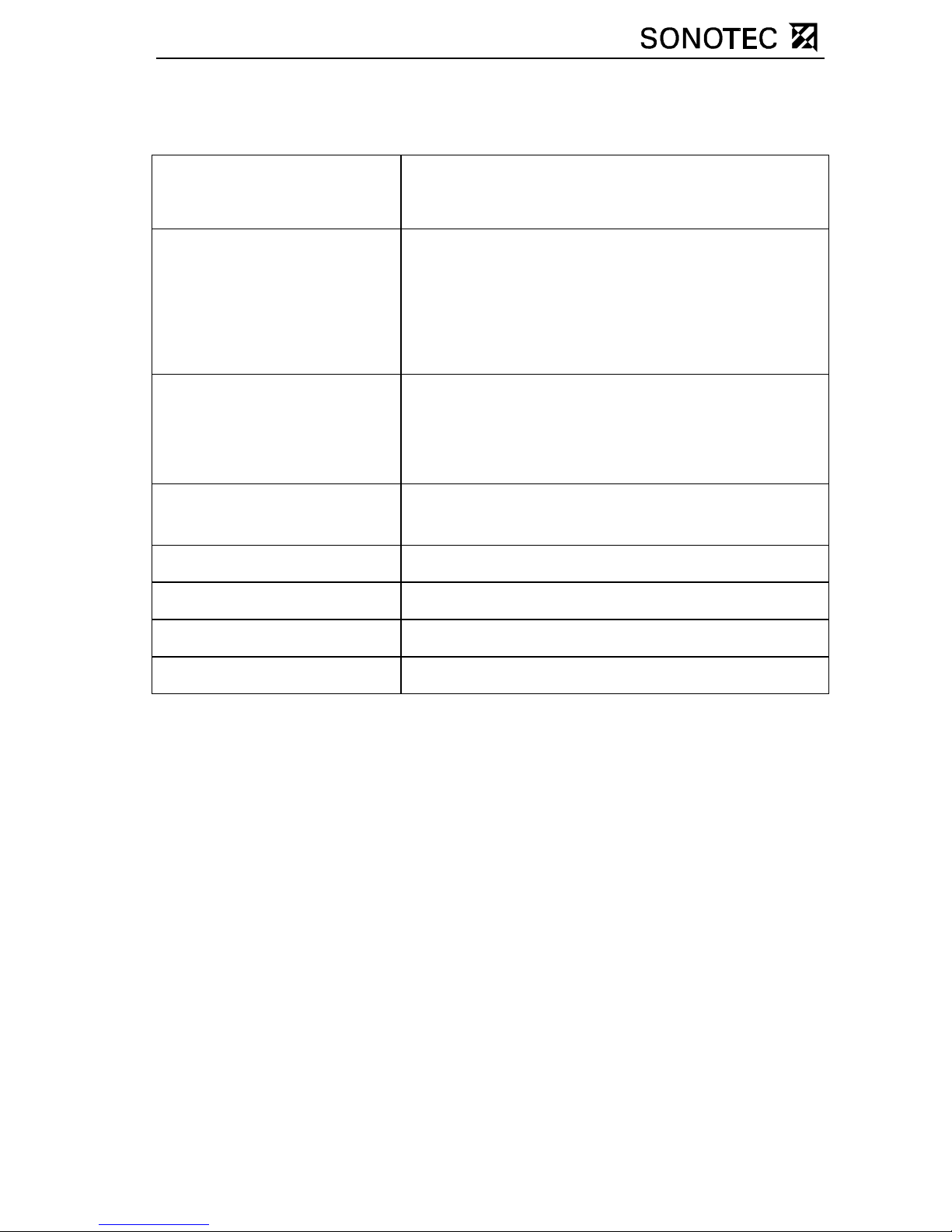
OM_SPHM_engl_Vers.1_2011-09-26 Seite 42
9 Technical specifications
Operating frequency about 40 kHz
(20 … 60 kHz width 2 kHz increments)
Connections Ultrasonic sensor
Temperature sensor
Headphone
USB interface (USB 2.0)
Display Graphical display
Background lighting
Menu control
Temperature
measurement range
0 … 800 °C
Dimensions 190 mm x 110 mm x 85 mm
Weight about 650 g
Operating temperature - 10 °C … +60 °C
Storage temperature -20 °C … +60 °C
Page 43

OM_SPHM_engl_Vers.1_2011-09-26 Seite 43
10 Warranty
SONOTEC Ultraschallsensorik Halle GmbH provides a warranty of
twelve months from the date of sale for the SONAPHONE M and T
(optional accessories) devices and their accessories. Within the
warranty period, SONOTEC Ultraschallsensorik Halle GmbH will correct
all defects caused by faults in material or manufacturing without extra
charge. SONOTEC Ultraschallsensorik Halle GmbH will fulfil the
warranty agreement by either repairing or replacing the defective device
or component.
Not covered by the warranty are primary or secondary batteries and
damages due to incorrect use, abrasion, or interference with the
equipment. Furthermore, the warranty does not cover those defects
which affect the value or usability of the equipment only insignificantly.
We reserve the right to make technical changes without notice.
Supply is based on availability.
 Loading...