

Page 1
STUDI/O
TABLE OF CONTENTS TABLE OF CONTENTS
HARDWARE INSTALLATION.......................................................................3
SOFTWARE INSTALLATION (PC WIN95 DRIVERS).................................. 4
SOFTWARE UNINSTALLATION (PC WIN95 DRIVERS) ............................6
SOFTWARE INSTALLATION (MACINTOSH STEINBERG ASIO
DRIVERS) ......................................................................................................6
WIN95 SOFTWARE TOUR/SETUP ..............................................................7
STUDI/O AUDIO DEVICE PROPERTIES.........................................7
TRAY.................................................................................................8
STUDI/O Status.................................................................................9
CONTROL PANEL..........................................................................10
FORMAT.........................................................................................11
ADVANCED FORMAT SETTINGS.................................................12
CLOCKS..........................................................................................13
METERS/MIXER.............................................................................15
INPUT & OUTPUT ROUTING.........................................................17
SETUPS..........................................................................................18
WINDOWS — ERRORS ..............................................................................19
MACINTOSH ASIO SOFTWARE TOUR/SETUP........................................ 21
AUDIO SYSTEM SETUP................................................................21
AUDIO INPUTS...............................................................................22
MASTER .........................................................................................22
MONITOR .......................................................................................23
DIGITAL CLOCKS, ADATS, DATS & DIGITAL MIXING CONSOLES ......24
BASIC SAMPLE CLOCK SETUP ...................................................25
SPECIFICATIONS .......................................................................................26
CONTACTING SONORUS ..........................................................................27
INDEX...........................................................................................................28
WARRANTY ................................................................................................29
TRADEMARK INFORMATION.................................................................... 29
2
Page 2
STUDI/O
STUDI/O INSTALLATION STUDI/O INSTALLATION & USAGE MANUAL & USAGE MANUAL
Thank you for purchasing the Sonorus STUDI/O interface card. We hope STUDI/O
enables you to spend more time on creativity and less time messing around with your
computer. Thanks to PCI Plug’n’Play, installation of STUDI/O is pretty
straightforward. There are no jumpers or anything to mess with!
HARDWARE INSTALLATIONHARDWARE INSTALLATION
The installation for Mac and PC is the same.
1. Turn OFF the power to your computer and any attached peripheral devices and
unplug their power cords.
2. Remove the cover from the computer case.
3. Locate an unused PCI expansion slot. Remove the bracket that covers the
card-slot opening (PC users, hang on to the bracket screw). PCI connectors are
shorter than ISA or EISA connectors and are typically white (Mac users, you can
doze off during this part). One or more slots in your PC may be shared ISA/PCI
slots. STUDI/O will work in any PCI slot.
4. Insert the STUDI/O card into the PCI slot. Press it down firmly so that the
contacts are securely seated in the slot.
5. When the STUDI/O card is firmly seated in the PCI slot, secure the bracket with
the screw you saved from Step 3. Mac users (are you with us?), your computer
may have a plastic latch instead of a screw. Deal with it!
6. Replace the computer’s cover: you’re ready to rock!
7. Thank you and good night!
3
Page 3
STUDI/O
SOFTWARE INSTALLATIONSOFTWARE INSTALLATION (PC Win95 drivers) (PC Win95 drivers)
1. Locate the STUDI/O Drivers floppy disk.
2. Turn ON the power to your computer.
3. The computer will tell you New Hardware Found. Select Driver from disk provided by
manufacturer and insert the STUDI/O Drivers floppy disk into the A: drive. Click on
the “OK” button.
4. When the Select Device window appears, make sure that the STUDI/O Audio Device
is highlighted (selected), then click on the “OK” button.
5. Windows will copy all the stuff you need onto your hard drive to some secret
Windows location.
6. Click on the “OK” button when Windows asks you if you
want to restart your computer. Once your computer is
restarted, the Sonorus logo should appear in the desktop
tray. This indicates that the software has installed correctly
and the hardware is operating properly.
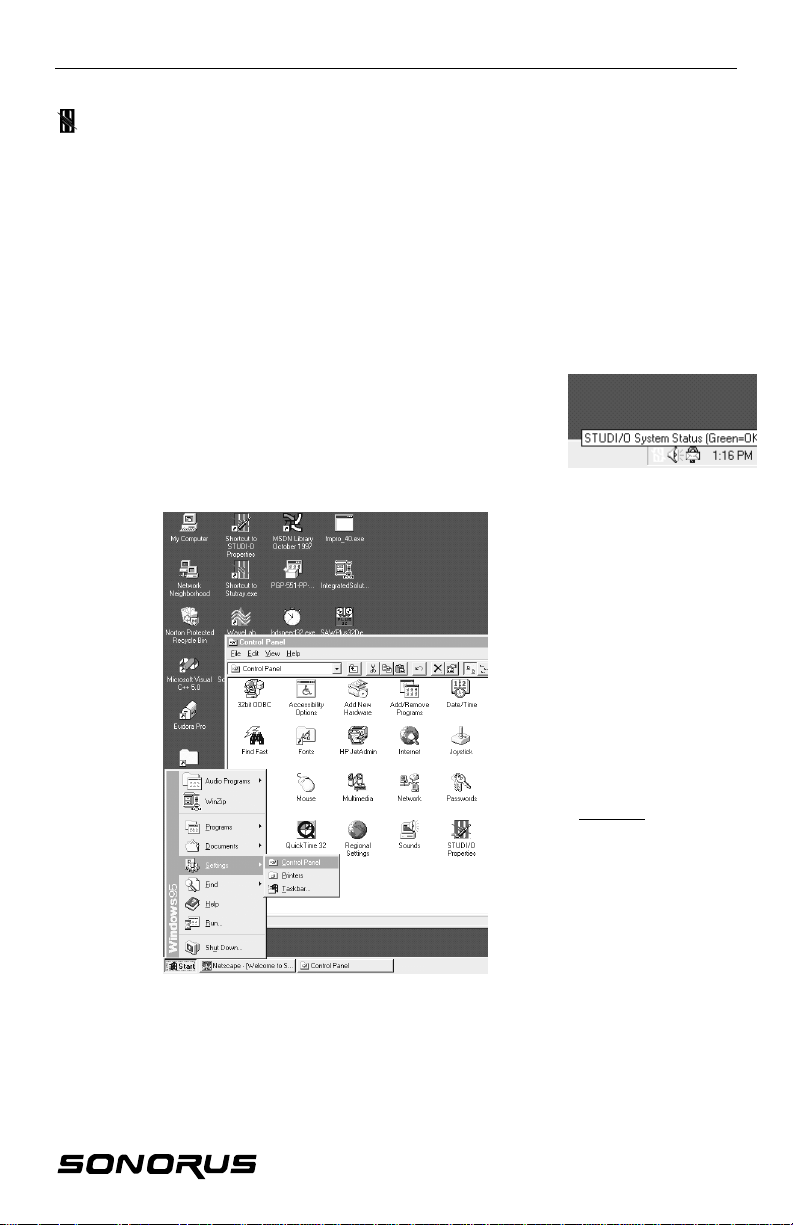
7. Check the Multimedia Control Panel.
To find the Multimedia Control
Panel:
• Click on the Start button.
• Go to Settings.
• Select Control Panel.
• In the Control Panel
window, click on Multimedia.
Sonorus recommends configuring
the Audio settings so that
Windows does not use STUDI/O
for its system I/O (like beeps,
etc.), or maps through it, etc.
4
Page 4
STUDI/O
Mapping
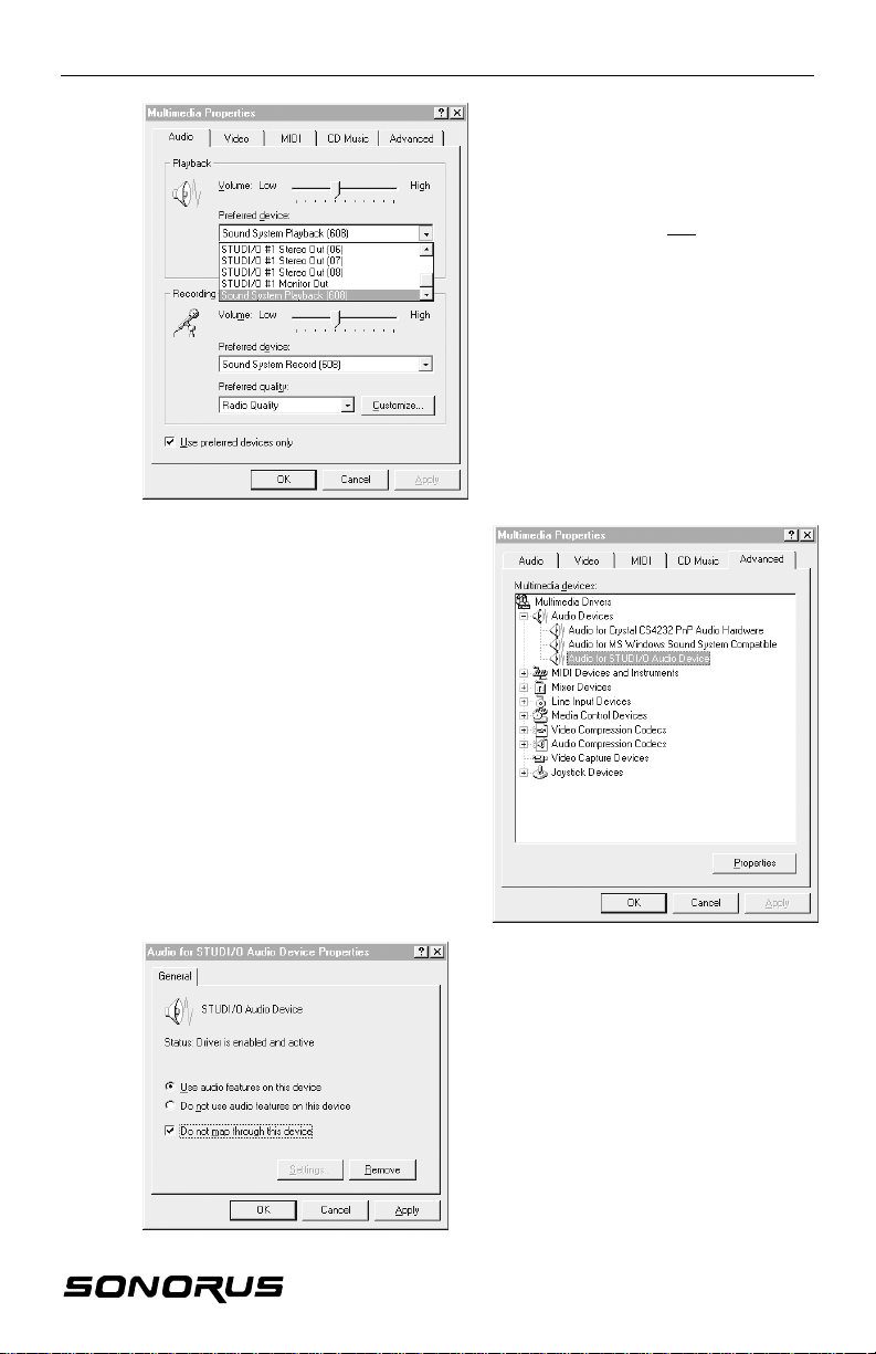
• Select the Advanced tab in the
Multimedia Properties window
(shown right).
• Double click Audio Devices,
highlight (single click) Audio for
STUDI/O Audio Device, and click on
the Properties button.
• Check the box next to Do not map
through this device in the Audio for
STUDI/O Audio Device Properties
window (shown below).
• Click on the “OK” button in the
Audio for STUDI/O… window and
again in the Multimedia Properties
Window.
Multimedia Control Panel, cont’d
System I/O
• Select the Audio tab.
• Under Playback or Recording make
sure STUDI/O is not selected as the
Preferred device.
8. Reboot your computer.
9. Please read the README.TXT file.
10. All you’ll need to do now is run our
control panel to set up the board (see
the WIN SOFTWARE YOUR/SETUP
section).
11. Thank you and good night!
5
Page 5
STUDI/O
SOFTWARE UNINSTALLATIONSOFTWARE UNINSTALLATION (PC Win95 (PC Win95
drivers)drivers)
Remove the STUDI/O card from your machine.
Follow these simple steps if you would like to uninstall the STUDI/O drivers.
1. Click the right mouse button on the My Computer icon and select
Properties from the full down menu.
2. From the System Properties window, locate STUDI/O Audio Device
under the Sound, video and game controllers icon and double-click.
3. Click on the Remove button.
Uninstall files
The following is a list of the files that the STUDI/O setup installs onto your hard drive
it the c:\windows\system directory. In addition you may want to remove other setup
files (*.ssf).
readme.txt
studio.inf
studio.vxd
studioui.dll
stutray.exe
factory.ssf
user.ssf
stupanel.cpl
SOFTWARE INSTALLATIONSOFTWARE INSTALLATION (Macintosh (Macintosh
Steinberg ASIO drivers)Steinberg ASIO drivers)
1. Locate the STUDI/O Drivers floppy disk.
2. Turn ON the power to your computer.
3. Drag the contents of the “ASIO.MAC” folder into the “ASIO drivers” folder you
use for Cubase VST (version 3.5 or higher).
4. Please read the README.TXT file!
5. Thank you and good night!
6
Page 6
STUDI/O
WIN95 SOFTWARE TOUR/SETUPWIN95 SOFTWARE TOUR/SETUP
The basic idea of this board is to provide a compatible interface with as many
programs as possible. To that end, we support the standard Microsoft Sound
System.
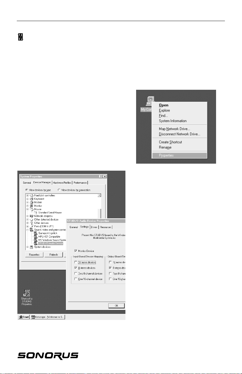
STUDI/O AUDIO DEVICE PROPERTIES
To open STUDI/O Audio Device
Properties:
1. Click the right mouse button on the
My Computer icon and select
Properties from the pull down menu.
2. From the System
Properties window, locate
STUDI/O Audio Device
under the Sound, video
and game controllers icon
and double-click.
Settings
The Settings tab is where you
select how you want the
STUDI/O card to appear in the
system.
Device Mapping (Input and
Output)
You can call our board “the
Chameleon”, because it can
appear to Windows as many
different sound cards. It can
look like eight stereo
soundcards. Sixteen mono
sound cards (who ever heard
of a mono sound card??), two
8-channel soundcards, one
16-channel sound card, or any
combination of the above!
7
Page 7
STUDI/O
STUDI/O AUDIO DEVICE PROPERTIES, cont’d
TRAY
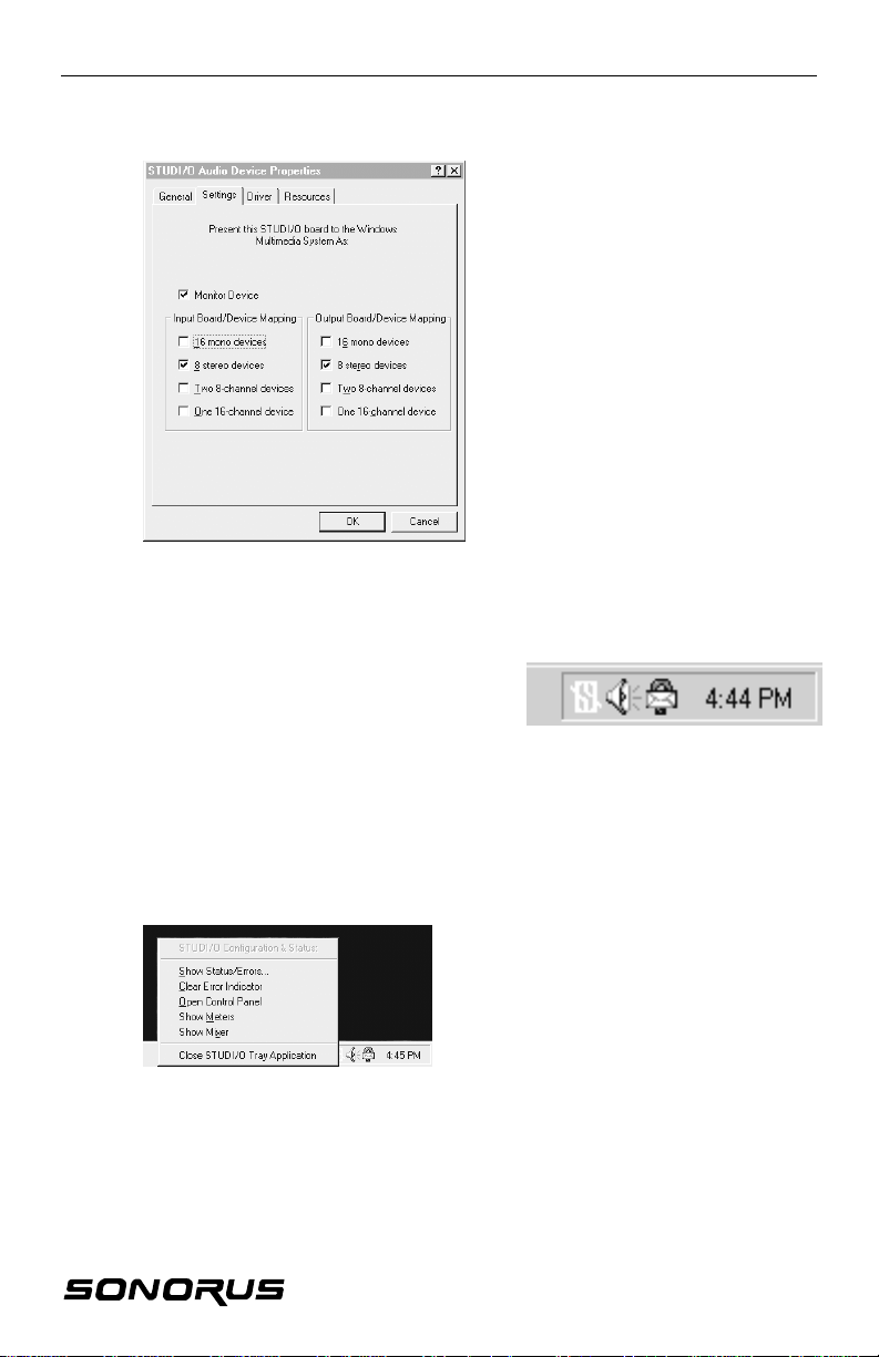
Little Icon
The Little Icon installed in your tray (at the
lower right side of your screen), indicates the
status of the STUDI/O card.
GREEN: Normally, the little icon is GREEN, indicating that the card is
RED: The little icon will turn RED if there is some kink of error, like bad
Little Menu
Click on the little icon to get the little menu.
Monitor Device
This checkbox gives you an
additional output pair directly to
the analog monitor outputs.
These are summed with the
regular monitor mix of the digital
ins/outs and sent to the analog
outputs. If you are using a
program that can generate a
separate monitor mix, you can
access the monitor outputs
directly.
working properly.
data, loss of clock, etc.
From the little menu, you can:
• Check status and error conditions,
• Clear Error Indicator,
• Open the control panel,
• Display the meter panel,
• Display the mixer panel, and
• Activate the Punch I/O panel (The
Sync Backplate option is required to
use Punch I/O).
8
Page 8
STUDI/O
STUDI/O Status
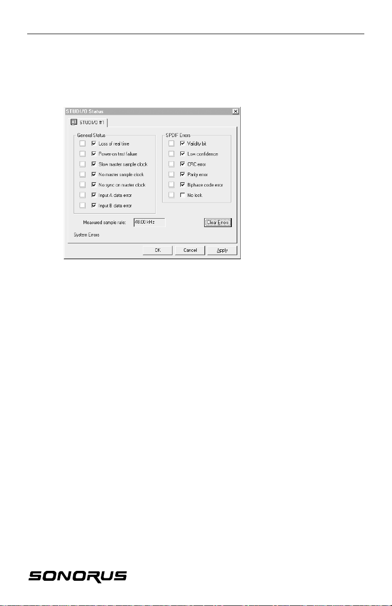
From the little menu (shown above) you access the STUDI/O Status window by
selecting “Show Status/Errors.”
General Status & SPDIF
Errors
The STUDI/O Status
window shows you why
the little icon turned
RED. A RED light
indicates an error
condition.
Note: All of the error
conditions are “latching”,
meaning that if they
happen once, the red
light will stay ON until
you click on the “Clear
Errors” button.
Check Boxes
The check boxes correspond to each error that you would like to be notified of.
When they are enabled (checked) the little icon will turn red when the corresponding
error occurs.
If you are not concerned with one or more of these errors, disable (uncheck) the
check box. If an error is disabled then the little icon will remain GREEN, even if the
corresponding error occurs.
Disable the Input A data error and Input B data error boxes when you aren’t using
either one of both of these inputs. This will prevent the little icon from constantly
turning RED when they are not in use.
9
Page 9
STUDI/O
CONTROL PANEL
Most of the cool stuff is in the Control Panel. This is where you set the sample rate,
clock source, and optical connector format, among other things.
A word about clocking (pun intended):
Digital audio, in all its glory, has a requirement analog doesn’t: everything has to be
completely in sync. If you drop a sample, all is lost! You’ll probably first notice the
click it produces after you’ve pressed 1000 CDs of your Magnum Opus.
The generally accepted approach for professional studios is to run everything off of
one master clock source, and keep everything at the same sample rate. This has
some profound benefits. You don’t have to worry about things going off pitch if it’s
playing back through a different output or different machine, you don’t have to worry
about transfers (once everything is set up!), your sound files are all consistent, etc.
With this approach, you only have to deal with different sample rates at the “edges” of
your setup. For example, if your main sample rate is 48KHz (which if you’re using
ADATs it probably is). then eventually you’ll find yourself needing to do sample rate
conversion to deal with CD players and CD recorders or DAT mixdowns for CD.
You’ve got the tools with STUDI/O, but the main point is that most of your time is
spent working on the project, and if everything’s the same sample rate, then you
have less headaches.
STUDI/O approaches the sample-synchronization issue with this in mind. It views
the world as having one basic clock rate, with some possible “fringe” peripherals that
have a different, or possible non-locked, sample rate. So, if you have two ADATs,
they have to be sample-locked with the 9-pin Alesis sync cable. If you have SPDIF
equipment, STUDI/O allows you to deal with common occurrences, as well as keep
things in sync.
In general, when you are recording (digitizing), you should have your A/D converters
be the master clock. This way, your initial recordings will have the lowest noise. This
is because every clock that has to lock to the master clock will exhibit some small
amount of jitter attenuation built in (like STUDI/O does). Of course, if your final
format is DAT or CD, then D/A noise won’t affect your recording; however, it is
annoying.
So, if you have ADATs, making them the clock source is generally recommended.
However, you may run into situations where you need to use STUDI/O’s onboard
clocks, such as when you set your ADATs to run at 44.1KHz internal (they are
actually running at 44.122KHz instead of 44.100KHz) or are outputting a different
sample rate via the Sample Rate Converter.
For each group of functions, there is a tab in the control panel. If you have more than
one STUDI/O in your machine, you’ll notice separate tabs for each, with
corresponding board numbers.
10
Page 10
STUDI/O
FORMAT
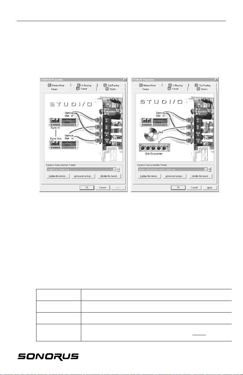
The Format tab is where you set up the format for the optical connectors. Various
combinations of ADAT and SPDIF are available, with the Sample Rate Converter
(“SRC”) inserted in different places. The diagrams show the function and appropriate
connections.
Shown here are two (2) different configurations that can be selected from the
External Interconnections Format pull down menu.
Explain this format…
Click on the Explain this format button to view a brief description of the format that is
currently being displayed in the External Interconnection Format pull sown menu.
Advanced settings…
Click on the Advanced settings button to view the Advanced Format Settings window.
Identify this board…
Click on the Identify this board button to cause the LEDs on STUDI/O and the optical
connectors to flash. This is helpful when you are trying to sort out different STUDI/O
cards and connectors. The following is a guide to use this function.
Identify a board
Identify Output A
Identify Output B
Identify Inputs
When you click on Identify this board the LEDs and optical
connectors will flash.
The light at then end of the cable flashes two quick flashes
followed by a short pause.
The light at the end of the cable flashes one quick flash hollowed
by a short pause.
Loop the output cable into the inputs. If Output A is connected to
Input A and Output B is connected then the lights do not flash. If
the lights are still flashing, they are cross-connected.
11
Page 11
STUDI/O
ADVANCED FORMAT SETTINGS
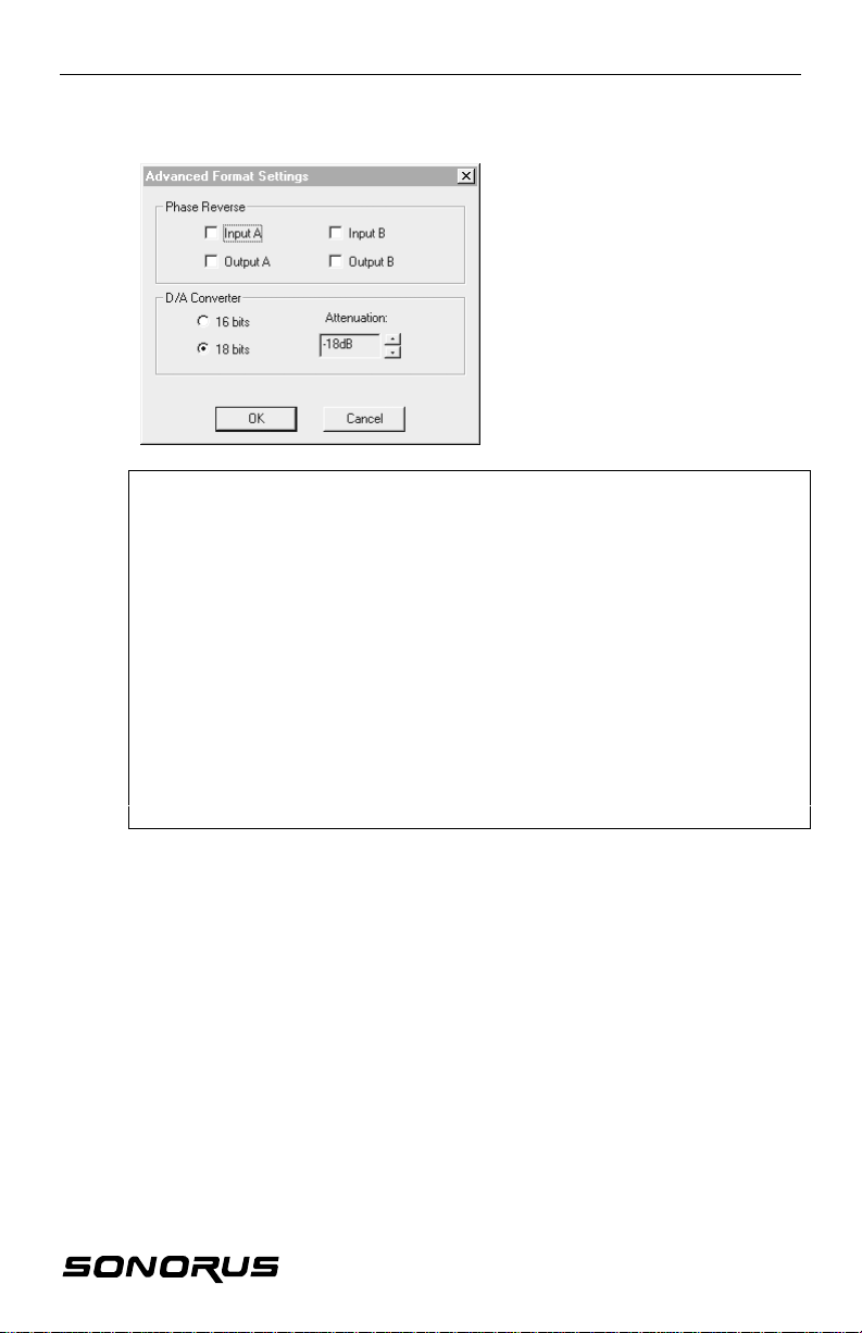
Phase Reverse
We put Phase Reverse for
each input and output to deal
with the old , original ADATs.
Here’s a quote from the
ADAT XT manual:
“The original ADAT was designed to invert its analog input signal internally before
the audio was sent through the A/D converter and recorded onto tape. The digital
representation of the data (as stored on tape) was therefore inverted relative to the
analog input (i.e., a positive voltage at the analog input is stored as a negative
number on the tape). When this digital signal was played back from tape, the data
was sent to a D/A converter, and the analog signal output of the D/A was inverted
once again before going to the output jacks. This resulted in the input to the output
phase being correct, and no phase problems were experienced when using a single
ADAT or multiple ADAT systems.
“However, neither the digital input not the digital output was inverted. Therefore, if
one transfers the ADAT’s digital audio data to a DAT machine or hard disk recording
system, the audio output from the other device would likely be out of phase with the
ADAT, since it probably does not invert the analog signal after its D/A converters.
“To prevent this from occurring, the XT design has been improved so that the polarity
remains constant from the analog to digital, and back to analog, domain.”
Moral of the story? Check the Phase Reverse box on any input and output that is
connected to an original ADAT; otherwise leave the box unchecked.
D/A (Digital to Analog) Converter
The D/A Converter section allow you to fine tune the D/A output to your liking.
16 and 18 bits
Select either 16 bits (which causes the D/A to dither to 16 bits) or 18 bits. The full
resolution of the D/A converter is 18 bits.
Note: The 18 bit monitor mix is rounded down to 18 bits for output via the D/A (and
24 bits via the digital outs) as explained in the “Meters/Mixer” section..
Attentuation
STUDI/O’s D/A converter has a built-in attenuator that we give you access to. Use
the attnuator if the maximum output level of the headphone/monitor jack is too “hot”
for your system.
12
Page 12
STUDI/O
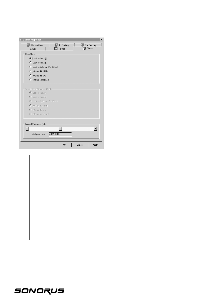
CLOCKS
The Clocks tab is where you set
up the source of sample clocks.
Lock to Input A or B
Select Lock to Input A or Lock to
Input B if you are trying to record
something.
Lock to External Word Clock
You’ll need the Sync Backplate
option to use the External Word
Clock.
Internal 44.1 kHz, 48 kHz, or
Varispeed
Select one of the internal clocks,
either the standard rates, or the
varispeed if you’re only playing
back and want STUDI/O to be the
sample clock master.
A note about ADATs:
When connecting to more than one ADAT, it is vital that they are all sync’d together
with the 9-pin sync connector(s). In this case, STUDI/O can sync to them via the
opticals.
Since the ADATs are in a chain, the sample clock jitter increases on each slave unit.
That’s why we generally recommend that you sync to the “optical IN” connected to
the ADAT higher up in the chain, toward the master and the other optical to the ADAT
lower in the chain. Of course this is true of all ADATs, regardless of the
manufacturer. It’s just the nature of a serial sync-chain.
You don’t have to worry about this when connecting to stuff like the Yamaha of Korg
digital mixing boards, as all their opticals are in parallel, not in series.
If you get some data errors when locked to one of the ADATs, try the other one;
maybe you’ll have better luck!
Sample Rate Converter Clock
The Sample Rate Converter Clock (shown grayed out) is activated when you’re using
the SRC (Sample Rate Converter) for an SPDIF output. When the Sample Rate
Converter is in use, select the source for the new sample rate for the output.
Note: You can get a 32KHz output rate by locking to an SPDIF input running at that
rate.
13
Page 13
STUDI/O
METERS/MIXER
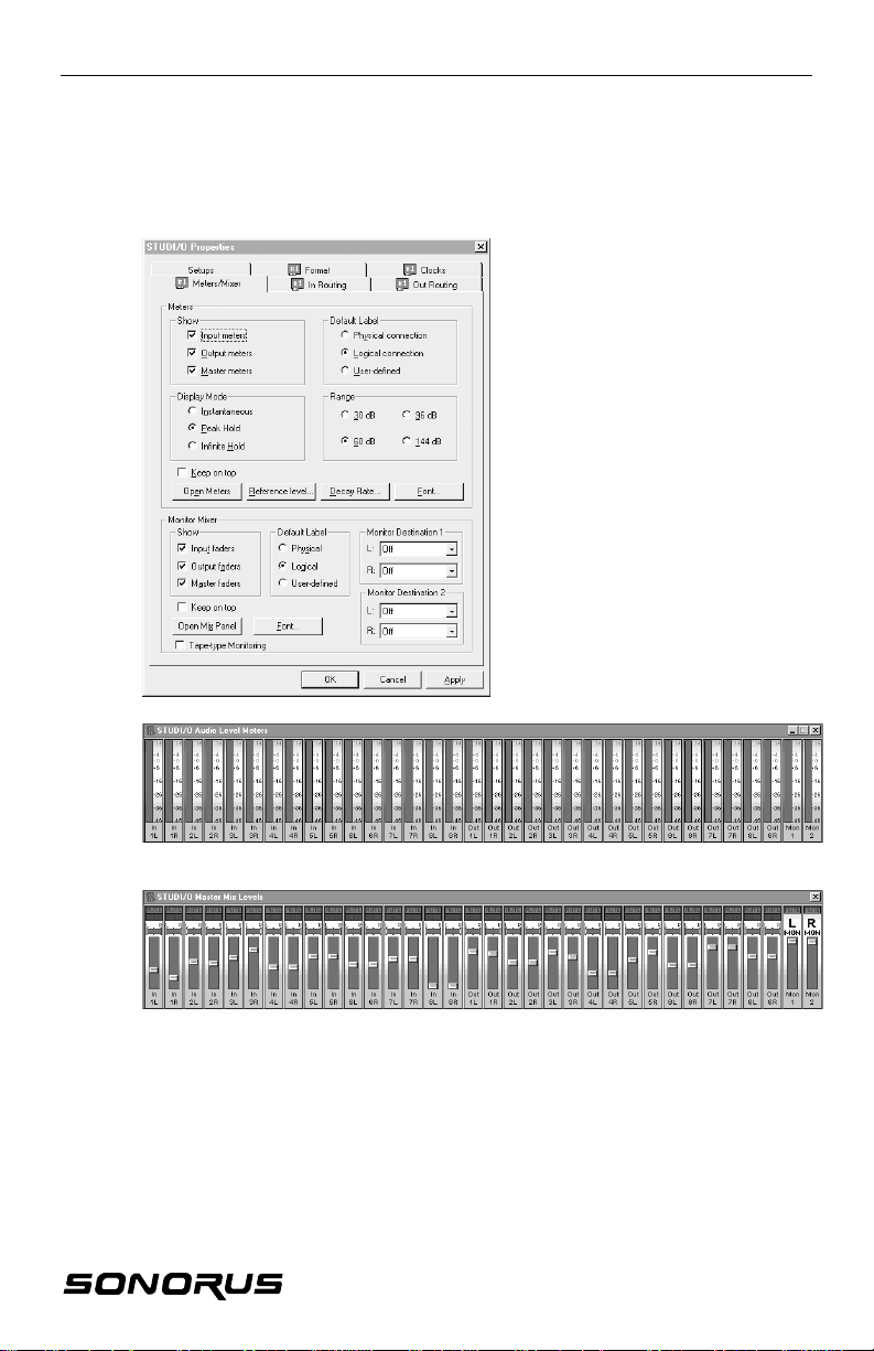
On the Meters/Mixers tab you can fine tune the appearance of the peak meter and
monitor mix fader panels.
What is the Meters panel, you
ask? Well, the meters are true
peak-reading meter. Hardware
on STUDI/O checks each and
every sample passing through
the board, and keeps track of the
peaks. So, what you see in the
meter panels are the true signal
peaks.
The range of meters can be
adjusted (no reason to waste
pixels on the noise floor of your
ADATs!) and labeling can be
controlled, so you can really
integrate them in with your
favorite editor.
The mixer allows you to create a
mix of all the input and output
channels, and send that to the
analog line/headphone output.
Studio Audio Level Meters
STUDI/O Master Mix Levels
Meters — Show
Use the check boxes to select which STUDI/O Audio Level Meters panels (Input,
Output, and/or Master) you would like to display.
Meters — Default Label
Select which connections you would like to assign to the STUDI/O Audio Level
Meters panel.
14
Page 14

STUDI/O
METERS/MIXER cont’d
Meters — Display Mode
Select which mode you would like to use for the peak level readings (Instantaneous,
Peak, or Hold).
Meters — Range
Select the decibel range you would like for the STUDI/O Audio Level Meters panel to
display.
Meters — Keep on top
Enable (check) the Keep on top check box to keep the STUDI/O Audio Level Meters
panel on the top of your desktop display.
Meters — Open Meters
Click on the Open Meters button to display the STUDI/O Audio Level Meters panel.
Meters — Reference level…
Click on the Reference level button to bring up a dialog box that allows you to select
the reference level you would like for the STUDI/O Audio Level Meters panel display.
Signal peaks above the reference will display in YELLOW, making it easy to monitor
your levels at a glance.
Meters — Decay Rate…
Click on the Decay Rate button to bring up a dialog box that allows you to adjust the
rate of decay of the peak level indicator.
Meters — Font
Click on the Font button to customize the type and size of the font used to label the
meters.
Monitor Mixer — Show
Use the check boxes to select which STUDI/O Mix Levels panel (Input, Output,
and/or Master) you would like to display.
Monitor Mixer — Default Label
Select which connections you would like to display in the STUDI/O Mix Levels panel.
Monitor Mixer — Monitor destination 1 & Monitor Destination 2
Use these drop down menus to route the monitor mix to any two (2) pairs of digital
output channels (serving as an el-cheapo mixer).
Monitor Mixer — Keep on top
Enable (check) the Keep on top box to keep the STUDI/O Mix Levels panel on the
top of your desktop display.
Monitor Mixer — Open Mix Panel
Enable the Open Mix Panel button to display the STUDI/O Mix Levels panel.
15
Page 15
STUDI/O
METERS/MIXER cont’d
Monitor Mixer — Font
Click on the Font button to customize the type and size of the font used to label the
mixer.
Monitor Mixer — Tape-type Monitoring
Enable (check the box) Tape-type Monitoring to playback the audio that is currently
being recorded on any given channel.
Mute and Solo
You can mute and solo channels, just like a real mixing board (hold the ‘Shift” key
down to solo groups of channels).
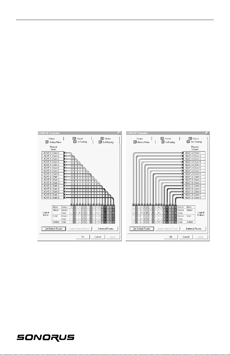
INPUT & OUTPUT ROUTING
The Input Routing and Output Routing tabs allow you to get extra fancy with your
patching. Here you can control what your Windows editing programs “see” for tracks.
You can easily reroute individual channels of your ADATs and/or DATs or whatever
you have hooked up, so that what your Windows programs “sees” as channel #1 can
be whatever you want. This might come in handy if your program won’t allow you to
remap or rearrange tracks on your screen. And, along with everything else in the
control panel, these can be saved as a named setup. This way, you can customize
the way you work.
16
Page 16
STUDI/O
SETUPS
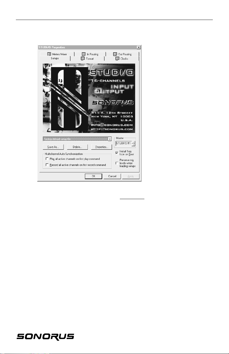
On the Setups tab you can save
and recall your setups. If your
have a couple of different ways
of patching together your studio,
you can quickly configure
STUDI/O to reflect your
repatching.
All of the settings from the other
tabs are saved in the setup, plus
the fader levels in your monitor
mixer, so it is a complete
snapshot of your STUDI/O
setup.
Save As…
Click on the Save As button to button to save a copy of the current set up. To
change the description, use the Properties button.
Delete
The Delete button deletes the currently selected set up.
Properties…
Click on the Properties button to change the “description” that is displayed in the pull
down window of the currently selected setup.
Multichannel Audio Synchronization
The Multichannel Audio Synchronization feature helps you deal with potential
Windows problems. For example, if you are using a multichannel audio editor via a
bunch of stereo drivers, Windows may have difficulty starting all the channels at
exactly the same time.
Note: Since STUDI/O runs all the channels off the same sample clock, interchannel
drift is a thing of the past!
17
Page 17
STUDI/O
WINDOWS — ERRORSWINDOWS — ERRORS
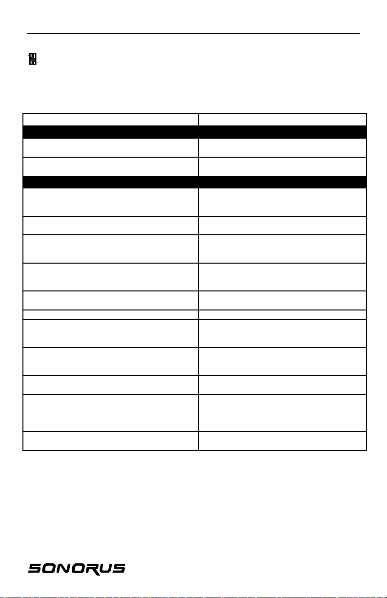
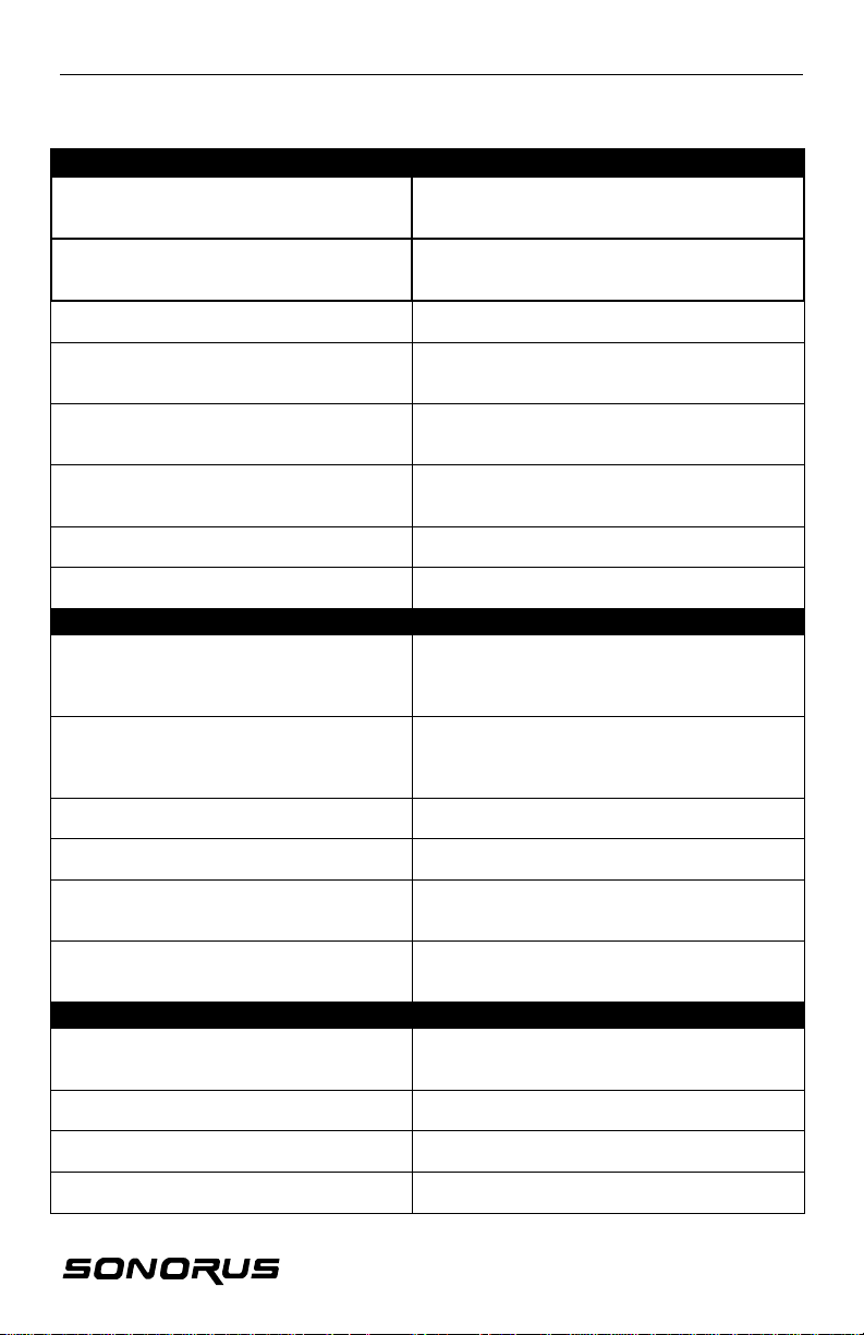
What Windows program would be complete without a wide array of error messages??
Seriously, though, here is a listing of all error codes generated by our software, with
explanations and remedies.
ERROR MESSAGE EXPLANATION/REMEDY
NON-FATAL ERRORS
“Cannot change mode at this time. STUDI/O Can only change modes when other
“Routing table is incomplete. You must route
all channels before continuing.”
SETUP FILE – RELATED
“Setup registry key was not found. Current
settings have been restored to the factorydefault settings.”
“Error: Cannot read setup file.” Uh oh! Disk corruption! Delete the current
“Setup registry key and factory default setup file
are missing. Restoring settings to basic values.
Please review all settings before proceeding.”
“Error: Cannot open setup file.” Our software couldn’t open the .ssf file that
“Error: Cannot write setup file.” Did you somehow set the .ssf file as “Read“Skeletal setup — no presets found” All of the .ssf files are missing!
“Error: No STUDI/O setup files found. Failed
to find any .SSF files in the Windows system
directory.”
“Error: Specified setup file is missing or cannot Our software couldn’t find the .ssf file that
“Error: Cannot delete setup file.” Did you somehow set the .ssf file as ‘Read“This setup file is erase protected and cannot
be deleted. To delete this file, first uncheck the
erase protect box in the properties for this
setup.”
“Error: Settings registry key is missing.” This could happen if you changed
programs are not playing or recording.
Pretty self-explanatory, no?
This could happen if you changed
motherboards. Try re-opening the desired
settings file.
.ssf file.
This could happen if you changed
motherboards, backed up your hard drive or
something. Try to reinstall our drivers.
was currently selected. Is something else
using the file?
Only’ from Windows or DOS?
Perhaps you should reinstall our drivers, or at
lest make a new .ssf file (by saving your
settings).
was currently selected. Maybe it got deleted
accidentally?
Only’ from Windows or DOS?
Please follow the directions stated in the
error message.
motherboards. Try reinstalling our driver.
18
Page 18
STUDI/O
BIG PROBLEMS…
“Error getting error/status information:
IOCTL failed. Future updates disabled until
reboot.”
“STUDI/O fatal error has occurred. To
restart the STUDI/O board, you must power
cycle your computer.”
“Board failed to respond to status query
after boot. A power cycle is necessary.”
“Unable to load DSP code. DSP
generating spurious data, not responding to
reset. A power cycle is necessary.”
“Unable to load DSP code. DSP not
responding to reset. A power cycle is
necessary.”
“Unable to load DSP code. DSP not
reading code from host interface. A power
cycle is necessary.”
“DSP code loaded, not did not boot
correctly. A power cycle is necessary.”
“DSP code loaded, but no cookie was
returned. A power cycle is necessary.”
PCI P’N’P WEIRDNESS
“Although this STUDI/O board was
detected, the driver was unable to
determine which PCI bus and slot it
occupied. Please contact Sonorus.”
“Although an IRQ was successfully routed,
the driver was unable to place it into the
STUDI/O board’s resource configuration.
Please contact Sonorus.”
“Unable to route interrupt to STUDI/O
board. See the Setting tab for details.”
“The driver was unable to allocate system
resources required to operate.”
“No STUDI/O boards found.” Are you sure you put the board in this
“There are too many STUDI/O boards
installed. The STUDI/O drivers support up
to four.”
SYSTEM/REGISTRY PROBLEMS
“Error: No STUDI/O status key in registry.” Either your registry got trashed (hope you
“Error: Undefined value in STUDI/O status Somehow the registry entry got trashed. Try
“Error: No system timers available for
STUDI/O tray application.”
“Tray icon installation failed.” Perhaps you have too many things in your tray.
Something got toasted. You don’t have to
power cycle the machine, just restart Windows.
Something got really toasted! Time for a power
cycle since that is the only way to reset the
onboard DSP.
Something got really toasted! Power cycling is
the only way the onboard DSP totally resets.
Something got really toasted! Power cycling is
the only way the onboard DSP totally resets.
Something got really toasted! Power cycling is
the only way the onboard DSP totally resets.
Something got really toasted! Power cycling is
the only way the onboard DSP totally resets.
Something got really toasted! Power cycling is
the only way the onboard DSP totally resets.
Something got really toasted! Power cycling is
the only way the onboard DSP totally resets.
We’ve never seen this, that’s why we want you
to contact us if your do! Theoretically it’s
possible.
We’ve never seen this, that’s why we want you
to contact us if your do! Theoretically it’s
possible.
Have you used up ALL your interrupts?
Generic catch-all error code… contact us if you
see it (we haven’t yet).
computer? If so, maybe it isn’t seated in the
connector properly.
Don’t you WISH you had this problem??
backed it up!) or you changed your
motherboard…
reinstalling our drivers.
Can this actually happen? Theoretically!
Get two trays (just kidding).
19
Page 19
STUDI/O
MACINTOSHMACINTOSH ASIO SOFTWARE TOUR/SETUP ASIO SOFTWARE TOUR/SETUP
The ASIO drivers are very simple. Most of the work is done by Steinberg’s Cubase
program.
Currently, STUDI/O uses a separate driver for each setup of the optical connectors.
So StudIO-16Ch provides the dual-ADAT configuration, while StudIO-10Ch provides
SPDIF in/out on the B connectors (with sample rate conversion on the input).
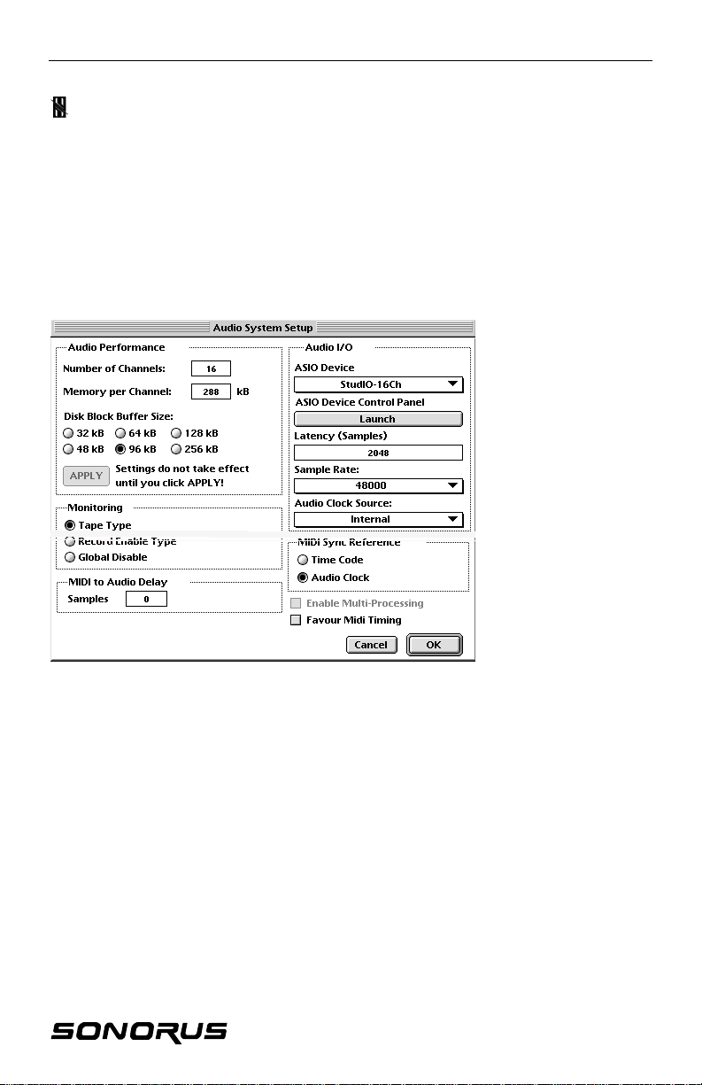
AUDIO SYSTEM SETUP
Within the System… (from
the Audio menu) panel you
can select the clock source
for the board, as well as
various system parameters
like channel buffer size,
etc. The Steinberg manual
has more information on
these and other
parameters.
Note: The “Monitoring”
setting should probably be
on either “Tape Type” or
“Record Enable Type.”
20
Page 20
STUDI/O
AUDIO INPUTS
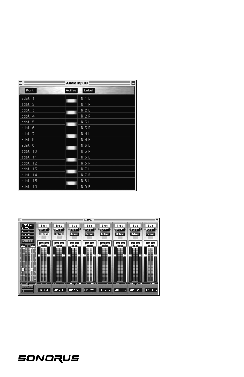
Audio Inputs
load. If you’re not
panel is where you
(about 1./2%), so you’ll want to
use only as many as you need.
Various inputs and outputs for the program’s audio can be selected within Cubase.
The labels are pretty self explanatory.
MASTER
Note: For multichannel recording,
enable the inputs you want in the
Inputs… Audio menu:
Relabel the channels in the
window to suit your taste, just click on
the Label and type a new one.
Be aware!: Each input that’s enabled
here adds to the CPU
using an input, turn it off; you’ll have
more horsepower for effects, plugins,
etc.
The Master
assign and activate Cubase
busses to STUDI/O outputs.
Note: Each active bus uses a
little more CPU bandwidth
Option-click the lower labels to get a pop-up menu with the choices for bus assignment. The
number of available outputs depends on which format you select. For ASIO-10ch, you get ten
(10) digital outs and two (2) analog (Monitor); for ASIO-16ch, you get sixteen (16) digital outs
and two (2) analog. Once a bus is activated, it becomes available in the Monitor panel for
assignment.
21
Page 21
STUDI/O
MONITOR
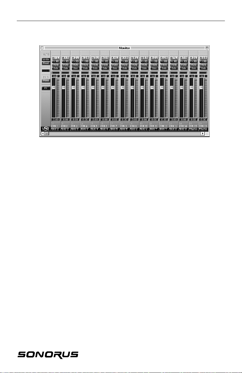
Use the Monitor panel to assign audio tracks to busses. You also assign inputs to
audio tracks for recording. Again, if you option-click the lower labels, you can assign
the bus for a particular track.
Note: The busses in Cubase are stereo; use the pan control to adjust between pairs.
Option–click the top labels to assign inputs to the tracks.
Note that the labels here track the labels set up in the “Inputs” window.
22
Page 22
STUDI/O
DIGITAL CLOCKS DIGITAL CLOCKS, ADAT, ADATs, DATs, DATs & DIGITALs & DIGITAL
MIXING CONSOLESMIXING CONSOLES
As we’ve stressed though this manual, digital audio has some unique requirements
concerning synchronization. One piece of equipment has to be the sample clock
master, another the slave.
Some digital tape decks are more flexible than others when it comes to confiruing
sample clocks.
1. “Original” (blackface) ADATs
These classic machines can select either the digital input as clock source, or
internal clock. Switch back and forth by holding the ‘SET LOCATE’ button and
pressing the ‘DIGITAL IN’ button. You can see the display indicate ‘int’ or ‘dig’.
Unfortunately you can only check by changing it, so don’t forget to change it
back.
2. ADAT XT/M20, Fostex CX-8/RD-8, Panasonic MDA-1
These newer machines have more buttons on the front… including a separate
button for CLOCK SELECT and DIGITAL INPUT/ANALOG INPUT. Thus, you
can easily select if the ADAT will follow its digital input or internal clock, and
whether it takes its input from its A/D converters or the digital input.
3. Consumer DAT machines
These behave such that if they are playing, they follow their internal clock, if
recording they follow the digital input if it’s selected. Many consumer DAT
machines don’t have the ability to play sound from their digital inputs when
stopped (they have to be in record-pause). Pro DAT machines usually are more
flexible and capable with clocking options.
4. Digital mixing consoles
Digital mixing consoles, like the KORG 168RC and the Yamaha O2R and O3D,
are very flexible in their clocking schemes.
With multiple ADATs sync’d together (with the 9-pin sync cable), the slave ADATs all lock to the
master. So with these rules, consider the settings of the master.
Now, what this all means can be boiled down to a few simple ideas.
23
Page 23

STUDI/O
BASIC SAMPLE CLOCK SETUP
1. “Original” (blackface) ADATs
When using blackface ADATs, whether you’re recording from an ADAT tape, or via the
A/D converter, set the board up to lock to optical input A or B. On the ADAT, set the
machine for ‘int’ (using the SET LOCATE and DIGITAL IN buttons as explained
previously). Now, the ADAT is always clock master. To listen back, simply switch the
ADAT XT from analog in to digital in.
2. ADAT XTs (and clones)
When using ADAT XTs, you can leave them on INT 48K (internal clock) and have the
board lock to optical A or B. To listen back, simply switch the ADAT XT from analog in to
digital in.
3. Consumer DAT machines
With consumer DAT machines, you would lock to the DAT machine if it’s playing or
monitoring it’s a/Ds. But when recording back from STUDI/O you would set STUDI/O to
internal clock. However, you can also record in from the DAT via the sample rate
converter, which allows the DAT (or digital-out CD player) to be unlocked or at a different
sample rate. In that case you’d select a different clock, like internal or the ADAT input.
4. KORG 168RC
With the KORG 168RC, set STUDI/O to Lock to A and set the 168RC to internal clock.
Select the customized 168RC format in the External Interconnection Format drop down
menu on the Format tab in the STUDI/O Properties window (wee the FORMAT section in
the WIN95 Software Tour/Setup section).
5. Yamaha O2R and O3D
With the Yamaha mixers, set STUDI/O to lock to one of its optical inputs, and set the
mixing console to run from its internal clock.
6. BRC, Midi Timepiece AV, etc.
With these types of synchronizers, all the ADATs slave to the synchronizer. So you can
think of the synchronizer as the master. So again, you have STUDI/O “follow the leader”
and lock to one of the optical inputs.
Hopefully these simple rules will keep you clocks locked and your studio rockin’!
24
Page 24
STUDI/O
SPECIFICATIONSSPECIFICATIONS
Size
6.85" × 3.85" (PCI 2.1 standard 'short card')
I/O Connectors
2 × TOSLINK optical receiver
2 × TOSLINK optical transmitter
1 × Stereo ¼” (tip-ring-sleeve) phone jack
Power Dissipation
3 watts
Digital I/O format
Each optical connector software selectable
between ADAT (8-channel) and SPDIF (DAT)
format.
Analog output
Max output: +10 dBm (into 600 ohms)
Total Harmonic Distortion + Noise: -94 dB
(0.004 %) unweighted
Gain Error: ±1 %
Interchannel Gain Mismatch: 0.1 dB
Gain Drift: 140ppm/° C
Interchannel Crosstalk (EIAJ Method): 101 dB
Interchannel Phase Deviation: ±0.1°
Software Attenuator Step Size: 1.0 dB
Software Attenuator Range Span: -62.5 dB
Software Mute Attenuation: -74.2 dB
Resolution: 18 bits or 16 bits with dither
(triangular PDF)
Onboard oscillators
44.1 KHz, low jitter low drift crystal type
48 KHz, low jitter low drift crystal type
Programmable timer, jitter attenuated
Low jitter L-C oscillator (VCO) for PLL
Synchronization
Basic sample rate syncable to onboard crystal
oscillators or to either optical input, regardless
of selected format.
Sample rate converter syncable to 'wild'
SPDIF input or output.
Sample rate converter
Stereo hardware sample rate converter
Dynamic Range: 96 dB
THD + Noise: -95 dB
Interchannel Phase Deviation: 0°
Hardware processing
True peak metering for every input, output,
and monitor channel.
Stereo monitor mix (48-bit summing) with
pan/level for each input and output.
Monitor mix assignable to digital outputs (as
well as analog output).
Software Drivers
Windows MM System (waveAudio) supplied
drivers
Configuration control panel
True Peak Meter window
Included accessories
4 x 2m TOSLINK optical cables
Windows 95 drivers (3 1/2" floppy)
CD-ROM demo with editing software,
soundfiles, etc.
Optional accessories
10m optical cables (package of 4)
25
Page 25
STUDI/O
CONTACTING SONORUS CONTACTING SONORUS
Having a bad computer day?
Well, email us or call us, we’ll try to help. If you need to return a board, call first and
get a Return Authoriuzation. And of coursek when all else fails, check out our web
site! http://www.sonorus.com is updated constantly. In fact, we consider our web
site our primary communication and documentation center. So if we have it, it’s on
the web, and it’s usually there first! Especially check the FAQ section, for quick
solutions to commen problems.
Our address: Sonorus, Inc.
111 East 12th Street, 2nd Floor
New York, NY 10003 USA
26
Page 26
STUDI/O
INDEX INDEX
16 bits, 12
168RC, 24, 25
18 bits, 12
24 bits, 12
32KHz, 14
44.1KHz, 10, 13, 26
48KHz, 10, 13, 26
ADAT, 10, 11, 12, 13,
15, 21, 24, 25, 26
ADAT XT, 12, 24, 25
ASIO, 21
BRC, 25
bus, 22
CD, 10
clocking, 10
clocks, 24
configurations, 11
Control Panel:
Multimedia, 4, 5;
STUDI/O, 8, 10
CPU, 22
Cubase, 21, 22, 23
Cubase VST, 6
DAT, 10, 12, 24, 25, 26
Device Mapping, 7
Digital Mixing Consoles,
24
error messages, 19
FORMAT, 11
Fostex CX-8/RD-8, 24
Input A: …data error, 9;
Lock to..., 13
Input B: ...data error, 9;
Lock to..., 13
INSTALLATION:
HARDWARE, 3;
Software (Mac
Steinberg ASIO
drivers), 6;
SOFTWARE (PC
Win95 drivers), 4;
STUDI/O, 3
ISA, 3
jitter, 10, 13
Korg, 13
KORG, 24, 25
LED, 11
Little Icon, 8
Little Menu, 8, 9
M20, 24
Mac, 3
MACINTOSH, 21
Mapping, 5
METERS, 15, 16, 17
Midi Timepiece AV,, 25
mixdowns, 10
MIXER, 15, 16, 17
monitor, 13
Monitor, 8
mute, 17
O2R, 24, 25
O3D, 24, 25
optical connectors, 11
Panasonic MDA-1, 24
PC, 3
PCI, 3, 26
Phase Reverse, 12
Punch I/O, 8
ROUTING, 17
SAMPLE CLOCK: setup,
25
Sample Rate Converter,
10, 11, 14
Settings, 7
SETUPS, 18
solo, 17
SPDIF, 10, 11, 21, 26
SRC. See Sample Rate
Converter
STUDI/O Status window,
9
Sync Backplate, 8, 13
System I/O, 5
tray, 4, 8
Uninstall files, 6
UNSTALLATION: (PC
Win95 drivers), 6
Varispeed, 13
Word Clock., 13
Yamaha, 13, 24, 25
27
Page 27
STUDI/O
WARRANTY WARRANTY
Sonorus, Inc. warrants, to the original purchaser, this equipment against defects in materials and
workmanship for a period of one year from the date of original purchase when the equipment is used
normally and is properly installed, including following standard static grounding procedures.
If you discover such a defect, as your sole remedy, Sonorus, Inc. will, at it’s option, repair, replace, or refund
the purchase price of the product at no charge to you, provided you return it during the warranty period, with
shipping prepaid, to the authorized Sonorus dealer from whom you purchased it or to any other authorized
Sonorus dealer or to Sonorus within the country of the original retail purchase and you obtain a Return
Authorization before returning your unit. Replacement unit may be an improved model, of at least equal
functionality. Attach your name, address, telephone number, email address (if you have one), and a
description of the problem, and a copy of the bill of sale bearing the appropriate serial number as proof of
date of original retail purchase, to each unit. International customers pay for all transportation.
This warranty applies only to the hardware parts of Sonorus products; Sonorus software, media, and
manuals are licensed and warranted pursuant to separate written statement. This warranty does not apply if
the product has been misused or it has been damaged by accident, abuse, misuse or misapplication, has
been modified without the written permission of Sonorus, or if any Sonorus serial number has been removed
or defaced.
ALL WARRANTIES, EXPRESS OR IMPLIED, OTHER THAN THE LIMITED WARRANTY ABOVE,
INCLUDING IMPLIED WARRANTIES OF MERCHANTABILITY AND FITNESS FOR A PARTICULAR
PURPOSE ARE EXCLUDED. WITHOUT FURTHER LIMITING THE GENERALITY OF THE FOREGOING,
SONORUS, INC. DOES NOT WARRANT (1) THE PERFORMANCE OR RESULTS OBTAINED FROM
USING THIS PRODUCT, (2) THAT THE PRODUCT IS APPROPRIATE FOR THE CUSTOMER’S
PURPOSES, (3) THE MANUAL IS ERROR FREE, OR (4) THAT NO DATA WILL BE LOST WHILE USING
THIS PRODUCT. THE ENTIRE RISK AS TO THE RESULTS AND PERFORMANCE IS ASSUMED BY THE
CUSTOMER.
THE WARRANTY AND REMEDIES SET FORTH ABOVE ARE EXCLUSIVE AND IN LIEU OF ALL
OTHERS, ORAL OR WRITTEN, EXPRESS OR IMPLIED. No Sonorus dealer, agent, or employee is
authorized to make any modification, extension, or addition to this warranty.
SONORUS IS NOT RESPONSIBLE FOR SPECIAL, INCIDENTAL, OR CONSEQUENTIAL DAMAGES
RESULTING FROM ANY BREACH OF WARRANTY, OR UNDER ANY LEGAL THEORY, INCLUDING
LOST PROFITS, DOWNTIME, GOODWILL, DAMAGE TO OR REPLACEMENT OF EQUIPMENT AND
PROPERTY, AND ANY COSTS OF RECOVERING, REPROGRAMMING, OR REPRODUCING ANY
PROGRAM OR DATA USED WITH OR STORED IN SONORUS PRODUCTS EVEN IF IT HAS BEEN
ADVISED OF THE POSSIBILITY OF SUCH DAMAGES.
Some states do not allow the exclusion of limitation of implied warranties or liability for incidental or
consequential damages, so the above limitation or exclusion may not apply to you. This warranty gives you
specific legal rights, and you may have other rights which vary from state to state.
Your opening of this package, your use of this product or your return of the Sonorus registration card
acknowledges that you have read and agreed to the terms of this Agreement. You further agree that it is the
complete and exclusive state of the agreement between us and supersedes any proposal or prior agreement,
oral or written, and any other communications between us relating to the subject matter of this Agreement.
TRADEMARK INFORMATIONTRADEMARK INFORMATION
STUDI/O, Sonorus, and are trademarks of Sonorus, Inc.
Microsoft Sound System, Win95, and Windows are trademarks of Microsoft Corporation.
Cubase is a trademark of Steinberg Soft - and Hardware GmbH
Macintosh is a trademark of Apple Computer, Inc.
Thank you and Good Night!
28
 Loading...