

Page 1
PPUH SONOPAN Sp. z o.o.
Poland, 15-950 Białystok, ul. Ciołkowskiego 2/2
tel./fax:+48 (85) 742 36 62
http://www.sonopan.com.pl
RADIOMETER – PHOTOMETER RF-100
USER'S MANUAL
Page 2

Table of contents
1. INSTRUMENT CHARACTERISTICS .......................................................................................... 4
1.1. Technical data........................................................................................................................ 4
1.2. Measure probe unit................................................................................................................. 5
1.3. Steer unit................................................................................................................................ 5
2. EQUIPMENT................................................................................................................................. 6
2.1. Basic equipment..................................................................................................................... 6
2.2. Extra equipment ..................................................................................................................... 6
3. BASIC ELEMENTS OF METER................................................................................................... 6
4. RESULTS FIELD (MAIN WINDOW)........................................................................................... 7
4.1. Measure window .................................................................................................................... 7
4.1.1. Measure result format .................................................................................................... 8
4.2. Measured value logarithmic indicator ..................................................................................... 8
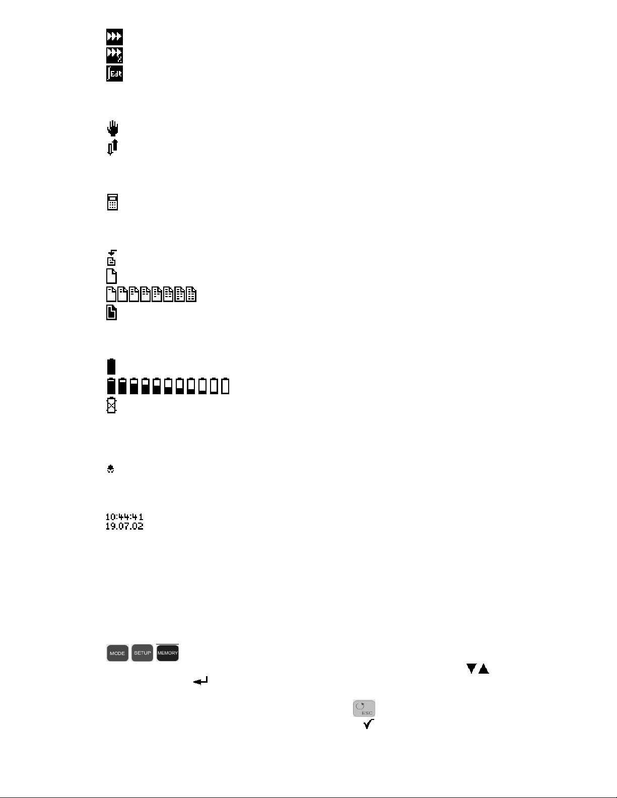
4.3. Status bar ............................................................................................................................... 8
4.3.1. Measure range field........................................................................................................ 8
4.3.2. Type of measurement field............................................................................................. 8
4.3.3. Measure range field........................................................................................................ 9
4.3.4. Statistics field ................................................................................................................ 9
4.3.5. Memory field ................................................................................................................. 9
4.3.6. Battery supply field........................................................................................................ 9
4.3.7. Alarm field .................................................................................................................... 9
4.3.8. Time / date field............................................................................................................. 9
5. SERVICE ACTIVITY.................................................................................................................... 9
5.1. System MENU....................................................................................................................... 9
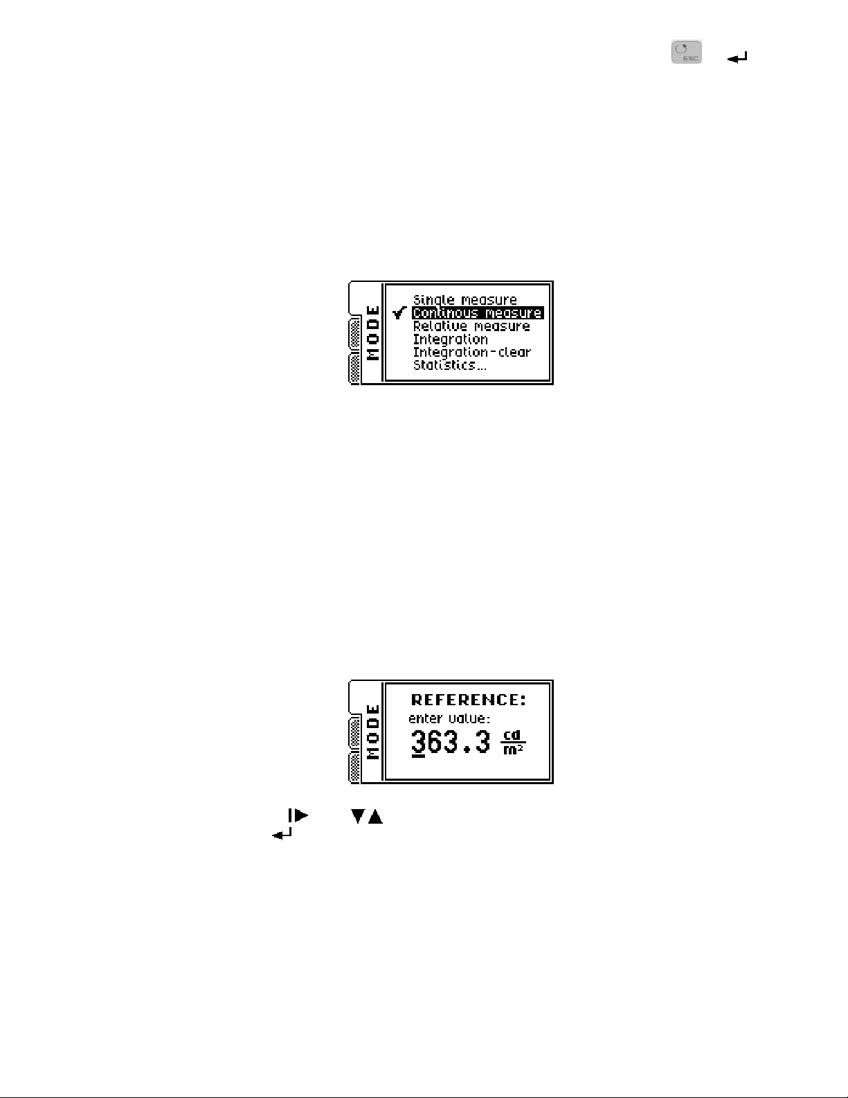
5.1.1. Menu TYPE OF MEASUREMENT............................................................................. 10
5.1.1.1. Single measure .................................................................................................... 10
5.1.1.2. Continuous measure ............................................................................................ 10
5.1.1.3. Relative measure ................................................................................................. 10
5.1.1.4. Integration........................................................................................................... 10
5.1.1.5. Integration-clear .................................................................................................. 11
5.1.1.6. Statistics.............................................................................................................. 11
5.1.2. Menu SETUP............................................................................................................... 11
5.1.2.1. Autorange............................................................................................................ 11
5.1.2.2. Zero setting ......................................................................................................... 11
5.1.2.3. Calibration........................................................................................................... 12
5.1.2.4. Luminancja ......................................................................................................... 12
5.1.2.5. Backlight............................................................................................................. 13
5.1.2.6. More.................................................................................................................... 13
5.1.3. MEMORY................................................................................................................... 14
5.1.3.1. Save measure....................................................................................................... 14
5.1.3.2. Load measure... ................................................................................................... 15
5.1.3.3. Clear last ............................................................................................................. 15
5.1.3.4. Clear all............................................................................................................... 15
5.1.3.5. Autosave... .......................................................................................................... 15
5.1.3.6. Send to PC........................................................................................................... 16
5.2. Starting instrument (power on sequence) .............................................................................. 16
5.3. Selecting measure range ....................................................................................................... 17
5.4. Measure ............................................................................................................................... 17
5.4.1. Single measure............................................................................................................. 17
5.4.2. Continuous measure..................................................................................................... 17
5.4.3. Relative measure.......................................................................................................... 17
5.4.4. Integrating ................................................................................................................... 17
5.4.5. Statistics ...................................................................................................................... 18
5.5. Measures memory................................................................................................................ 18
5.5.1. Working with external memory.................................................................................... 18
5.6. Working with luminance accessory ...................................................................................... 18
5.7. Working without measure probe........................................................................................... 19
5.8. Switching instrument off ...................................................................................................... 19
– 2 –
Page 3

6. COMMUNICATION WITH PC................................................................................................... 20
6.1. Transmission protocol .......................................................................................................... 20
6.2. Automatic power on............................................................................................................. 20
6.3. Controlling computer program ............................................................................................. 20
7. POWERING................................................................................................................................. 20
7.1. Control of battery supply. ..................................................................................................... 21
7.2. Automatyczne wyłączanie. ................................................................................................... 21
8. EXPLOITATION RECOMMENDATION ................................................................................... 21
9. WARRANTY AND REPAIRS..................................................................................................... 21
10. CE MARKING AND EEE DIRECTIVE.................................................................................. 23
11. APPENDIX A: Photometric probe G.L-100............................................................................. 24
12. APPENDIX B: Instrument probe for measure ultraviolet irradiance UV-A G.UVA-100........... 25
13. APPENDIX C: Instrument probe to measure photochemical (blue light) retinal hazard
G.BLH-100 .............................................................................................................................. 26
14. APPENDIX D: Instrument probe to measure photosynthetic active radiation G.PAR-100 ...... 27
15. APPENDIX E: Luminance accessory PL1.-RF100.................................................................. 28
16. APPENDIX F: Accessory PL-68 to measure luminance with luxmeter instrument ................. 29
– 3 –
Page 4

1. INSTRUMENT CHARACTERISTICS
Radiometer-Photometer RF-100 belongs to the family of RF-1xx devices (where xx is numerical
designation). Device structure is based on concept of separation device function onto probe with is complete meter and user steer unit which role is link user steering device with probe. This concept of device
allows operating with many probes with can have different metro-logic function. Under notion of metrologic function includes here: frequency characteristics of detector, number of measure ranges, dynamics
of a range, number of sub bands, physical units. Type of measure probe decides about complete measurement device function, so it can be photometer or radiometer with arbitrarily defined spectral optical
radiation relative sensitiveness. Steering unit has saved list of probes together it can operate (named allow
list), and it has predefined maximal firmware version of probe with it can operate. It allows in easy way
to evolve into both device types with backward compatibility into older versions.
Radiometer-Photometer RF-100 is designed to co-operate with measure probes type G.xxx-1xx
(where x is numerical designation of type) manufactured by SONOPAN. Metro-logic parameters of suite
(steer unit plus measure probe) depends on used probe unit, that is used for measurement radiation intensity or illumination intensity. For several kinds of measure probe units luminance mode was proposed
(energetic or depending on relative spectral probe sensitiveness. Measurement of luminance is available
after attaching proper accessory with measure filed angle 1°, 3° or 10°.
For example, instrument RF-100 with measure probe type G.L-100 makes luxmeter that fulfill regulation needs (PN-89/E-04040.00 Measuring optical radiation. Photometric measures. General regulations;
PN-89/E-04040.03 Measure lighting intensity; Enactment number 31 Chairman's of Main Measure Office from 20.03.1995 regarding introduction of regulation about metro logical luxmeters. Journal of Legal
Measure Nr 6 from 22.03.1995) for device class 5.
This probe and steer unit was approved by Main Measure Office and has got sign: RP T 02 197. Metrological is exactly same as manufactured by SONOPAN luxmeter L-100 instrument.
Radiometer-Photometer RF-100 was designed with integrating measurement function. This option makes
possible irradiation and exposure measurements.
This instrument is basic photometric device directed for all measuring services and employee of optical
radiation laboratory.
In range of electromagnetic compability Radiometer-Photometer RF-100 grants claims of norms:
EN61326 „Electrical equipment for measurement, control and laboratory use. EMC re-
quirements ”.
EN61000-6-2 „Electromagnetic compatibility (EMC). Generic standards. Immunity standard
for industrial environments ”
EN61000-6-3 „Electromagnetic compatibility (EMC). Generic standards. Emission standard for
residential, commercial and light-industrial environments ”
1.1. Technical data
• Precision class: depends on probe unit (look appendix)
• Entire error: depends on probe unit (look appendix)
•
Spectral matching: depends on probe unit (look appendix)
• Direction matching: depends on probe unit (look appendix)
• Measuring ranges: depends on probe unit (look appendix)
• Detector: individual for measurement probe unit type
• Display: graphical LCD 128×64 pkt.,
• Supply: battery 9V (6LR61)
•
Dimensions: 152 × 83 × 33 mm
• Operation temperature: 0 ÷ 40ºC
• Max environment relative humidity: 80%
Device is provided with several user functions :
• Manual or automatic change of measuring range ,
•
Single-time measurement or continuous,
•
Relative measurement with optional reference ,
– 4 –
Page 5

•
Integration of measured quantity in respect of time,
•
Measurement statistic independently for peek and integrated values:
• counting average value,
•
finding minimal value,
•
finding maximal value,
• counting ratio min/avg,
•
counting ratio min/max,
•
Manual or automatic adding measurement to statistics,
•
Measure memory: 512 cells with user comment space,
•
External memory for measurements (511 cells),
• Browsing and Viewing measures saved in memory,
•
Continue measurement record saved in memory,
•
Manual or automatic writing measures to memory,
• PAUSE driver – stopping measurement process,
•
Zero setting measure probe driver (detector dark current),
•
Automatic zero setting driver,
• Steering for calibrating measurement probe,
•
Two-way communication with computer through RS232C port,
•
Option that allows switching on and off steer unit through RS-232C interface,
• Choice of RS232C port speed,
•
Calendar and real time clock,
• Alarm with user comments ( e.g. remind about calibration deadline (date) ) ,
•
Supply voltage control,
•
Two automatic turn off drivers with changeable inactive time value,
• Two automatic back light LCD screen drivers.
The device user options are available through expandable menu lists visible at graphic display.
Radiometer-Photometer RF-100 consists of two cooperate units: measuring probe and it's steer unit.
1.2. Measure probe unit
Measuring probe type G.xxx-1xx is complete photometer which include :
•
radiation detector spectrum and direction corrected,
• analog-digital converter,
•
zero setting driver,
•
automatic zero setting driver,
• automatic measure range change driver,
•
register for calibration value,
•
communication interface witch steering unit.
1.3. Steer unit
Steer unit type RF-100 provide :
•
communication with measurement probe,
• visualization result of measures witch units,
•
handling measure device by user,
•
communication witch computer.
– 5 –
Page 6
2. EQUIPMENT
h
i
d
d
e
n
c
a
l
i
b
r
a
t
e
b
u
t
t
o
n
b
a
c
k
l
i
g
h
t
b
u
t
t
o
n
2.1. Basic equipment
•
Steering unit RF-100,
• Measure probe type, order dependent (optional),
•
Cable to communicate with PC,
•
Supply battery,
• Computer software handling measurement device,
•
User's manual,
•
Guarantee card .
2.2. Extra equipment
•
Attachment for measuring luminance PL1.RF-100 – measure field angle 1°,
• Attachment for measuring luminance PL3.RF-100 – measure field angle 3°,
•
Attachment for measuring luminance PL10.RF-100 – measure field angle 10°,
•
External memory module MP32.RF-100 – memory 32KB (511 cells),
• Hook for photometric probe,
•
Transport suitcase.
Inside transport suitcase there are profiled soft nests assigned for placing all basic and extra equipment
elements. They provide proper storage and transport conditions that don't expose content on mechanical
damages.
BASIC ELEMENTS OF METER
3.
RADIOMETER
D
A
E
B
MODE
SETUP
ESC
0
F
C
P
M
Q
N
4
R
O
–
Y
@
Z
8
#
/
1
5
9
RF-100
G J
H K
2 3
I L
S V
T W
6 7
U X
$ +
% !
& ?
display
external memory socket
alphanumeric keyboard
measure probe socket
ext. power supply / PC socket
keyboard
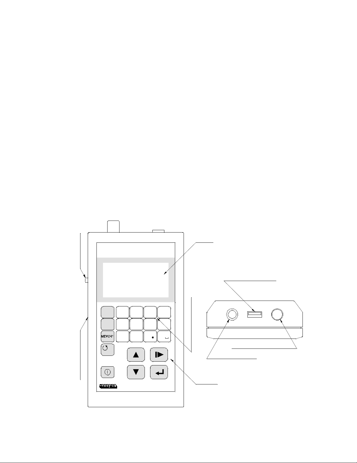
Illustration 1. Radiometer-Photometer RF-100
– 6 –
Page 7
4. RESULTS FIELD (MAIN WINDOW)
Main window of steering unit was named after content of graphics display, when all bookmarks of
MENU are disabled, when starting winieta is off and when there is no displayed communicate on instrument screen.
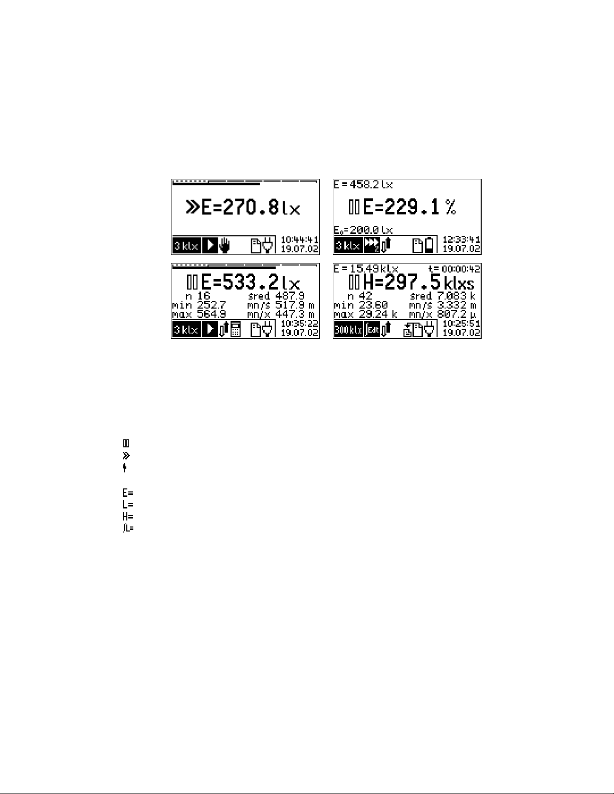
Main display window consists from measuring window, logarithmic bar of measured value and strip of
status.
Illustration 2. Main Window view for light intensify , relative measurement, statistics and integration
mode
4.1. Measure window
Measure window includes:
•
battery life indicator:
pause,
measure,
• Measure range overflow indicator with is displayed after measure state indicator,
•
measure value determination:
illumination
luminance,
luminance exposure (time integral intensity of illumination),
luminance time integrating,
•
measured value filed,
•
measured value unit field.
Besides:
for relative measurement mode: actual measured value (E) and reference value (E0) ,
for integral measurement mode: actual measured value (E) and integration time (t) in format
hours:minutes:seconds,
for statistics and integration mode: statistics field including: measures count (n), minimal value (min),
maximal value (max), average value (avg), min/avg ratio (mn/a),
min/max ratio (mn/x).
In measure value unit field, before basics unit, instrument prints a symbol of multiple or sub multiple.
Measure values displayed in statistic field do not includes designation of basic unit. They are similar to
computed factors and adjusted to multiplication factor symbols.
Device own proper to show value considerably surpass dynamics of measure probe displaying symbols:
•
f (femto) = ×10
•
p (piko) = ×10
-15
-12
• n (nano) = ×10-9
– 7 –
Page 8
• µ
(mikro) = ×10-6
•
m (mili) = ×10-3
• k (kilo) = ×103
•
M (mega) = ×106
•
G (giga) = ×1012
• T (tera) = ×1015
•
P (peta) = ×1018
4.1.1. Measure result format
Measure result is reeded from probe and displayed in result field of measure window with setup measure
result resolution. In case when measure value is greater then 9999×LSB (where LSB is weight of less signify bit), there is a clipping of showed number for four most signify digits. Position of decimal point and
unit fold are pre-selected, in order to present result with best precision.
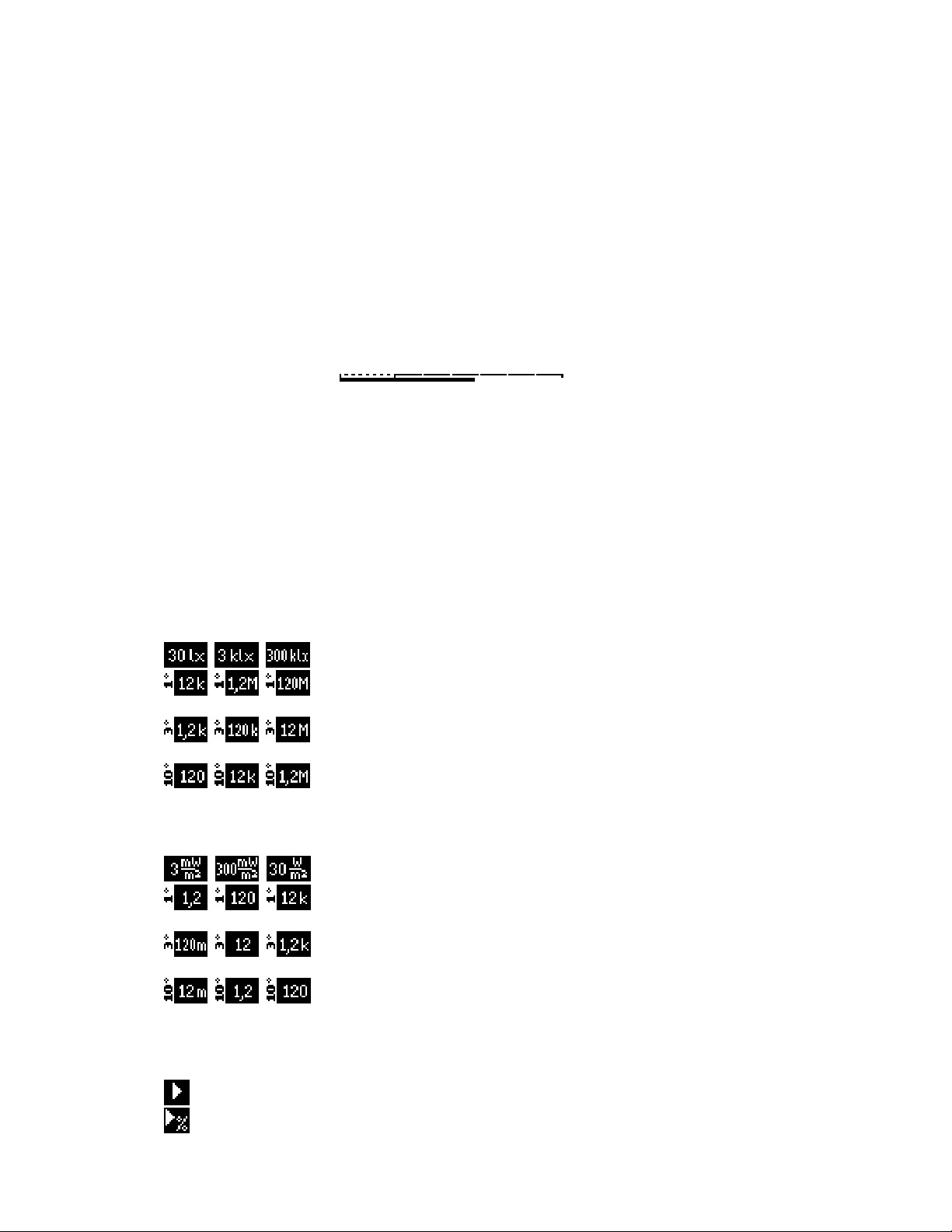
4.2. Measured value logarithmic indicator
Measured value indicator : is placed in upper part of screen. Indicator
is displayed during illumination measure without relative measure or statistics option selected. It includes
scale fold that covers whole measuring range and strip of fulfillment. Doted part of scale fold covers
lower range. If strip of fulfillment is in this area it signifies, that measurement is possible with greater
resolution on lower range. Indicator is not refreshed during return from option MENU to main window.
4.3. Status bar
In lower part of screen meter signalize actual setup of the device by icons. This field is divided into:
measure range field, measure type filed, measure change range field, statistics field, memory field, power
supply control field, alarm field, time / date field.
4.3.1. Measure range field
example photometric probe unit:
actual selected illumination measure range,
actual selected luminance measure range for 1° measure field angle
[cd/m2],
actual selected luminance measure range for 3° measure field angle
[cd/m2],
actual selected luminance measure range for 10° measure field angle
[cd/m2],
example radiometric probe unit:
actual selected irradiation measure range,
actual selected luminance measure range for 1° measure field angle [W·m
actual selected luminance measure range for 3° measure field angle [W· m
2
·sr–1],
2
·sr–1],
–
–
actual selected luminance measure range for 10° measure field angle
[W·m–2·sr–1].
4.3.2. Type of measurement field
one time measure,
one time relative measure,
– 8 –
Page 9
continuous measure,
relative continuous measure,
integration.
4.3.3. Measure range field
manual measure range change (only for one time measurement),
automatic measure range change.
4.3.4. Statistics field
automatic adding measure to statistics..
4.3.5. Memory field
automatic write measure to memory,
memory is empty,
memory is partly full,
memory is full.
4.3.6. Battery supply field
Battery is full,
Battery is partly empty,
Battery is empty,
4.3.7. Alarm field
Alarm is active.
4.3.8. Time / date field
Actual time or date is shown in lower right corner of a display. In case when viewing
measures from memory this field displays time and date of saved measure.
5. SERVICE ACTIVITY
5.1. System MENU
System MENU of Radiometer-Photometer RF-100 contains three basics bookmarks : TYPE OF MEASUREMENT, SETTINGS, MEMORY. Bookmarks are executed through instrument keyboard keys:
. All bookmarks contains list of available choice options. User can change setup options
by changing the position of pointer (option displayed in negative) by keyboard keys and apply the
setup values by key . Sub options menus texts are ended with three dots (expandable menu). Instrument memorize last position of menu pointer.
Canceling setup options is available through keyboard key .
Actual selected options are signalized in list by the checkout .
– 9 –
Page 10
The info screens that are shown during setup of device can be disabled by keyboard key or .
Changing instrument setup can be only made on pause mode. All setup values and positions of pointers in
menus are memorized in instrument memory and will be available after power on / off sequence.
5.1.1. Menu TYPE OF MEASUREMENT
Instrument can operate in three types of measurement (one of three):
• one time measure,
• continuous measure,
• integrating.
Additional, for one time measure or continuous measure provided relative measure option (type on/off).
Illustration 3. Bookmark menu TYPE OF MEASUREMENT with continuous measure option set.
5.1.1.1. Single measure
Function: starting one time measure mode, other setup stay the same.
5.1.1.2. Continuous measure
Function: stating continuous measure mode, automatic measure range option is on after switching to this
mode.
5.1.1.3. Relative measure
Function: Setting relative measure option on/off.
After setting measure option to „on” new window for setup reference value opens. Window contains last
measured default value for reference:
Edit can be made by passing numeric values directly from alphanumerical keyboard. Position of cursor
can be modified by key . Keys change multiplication factor of unit. Approving reference value
can be made by key . After that instrument change operation to automatic measure range change. If
that option was selected during integrating mode, one time measure mode is selected by the instrument.
5.1.1.4. Integration
Function: starting integration measure mode.
Instrument loads last parameters and values after switching to this mode. This leave option for user to
continue last integral measurement. Result value of actual illumination is rewritten from last one time
measure or continuous measure. After leaving integrating mode (switching one time measure mode, continuous or relative measure), in the result field instrument displays last measured value of illumination
during integral operation mode.
– 10 –
Page 11
5.1.1.5. Integration-clear
Function: Deleting measured integrated value and it's related statistics.
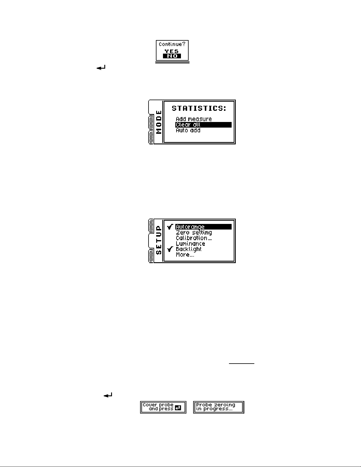
Instrument displays notice window: . After selecting true response and approving it by
keyboard key meter delete measured integrated value and it's related statistic values.
5.1.1.6. Statistics...
Function: statistics sub menu:
• Add measure - adding last measure to statistics.
• Clear all - delete (after approving the notice window) statistics .
•
Auto add - on/off appending data to statistics after every measure.
Statistic option only concern one time measure and continuous measure. In integrating mode instrument
make independent statistical calculation.
5.1.2. Menu SETUP
Illustration 4. Bookmark menu SETTINGS with setup options : automatic measure range change and
display back light on.
5.1.2.1. Autorange
Function: on/off automatic measure range.
Setting this value to off is equal to setting manual measure range change. In this case one time measure
will be set automatically.
5.1.2.2. Zero setting
Function: compensating photo detector probe dark current.
WARNING! Zero setting the instrument probe can be made only after covering measure probe.
If measure probe at zero setting process is not covered, instrument may work improperly.
On display screen instrument will remind about covering measure probe, and after approving wish to zero
set probe by key instrument display communicate about status of process.
Zero setting measure probe process on all measuring ranges. Values of zero setting are saved in internal
registers of measure head.
– 11 –
Page 12
5.1.2.3. Calibration...
Function: Calibration of measure probe.
WARNING! Calibration is made by proper Main Measure Office or Laboratory during in
strument calibration process. In other case instrument indications will not ap
prove standard pattern.
In order to perform calibration process correctly it is necessary to have proper photometric pattern (light
direct pattern) and conditions for correct illumination model restoring on surface of receipt field of measure probe.
Calibration must be done on any range for intensify level about 3/4 measure range.
Before calibrating instrument probe, pre-calibration measure witch photometric pattern is required.
After selecting Calibration from menu OPTIONS new edit window for measured calibration value will
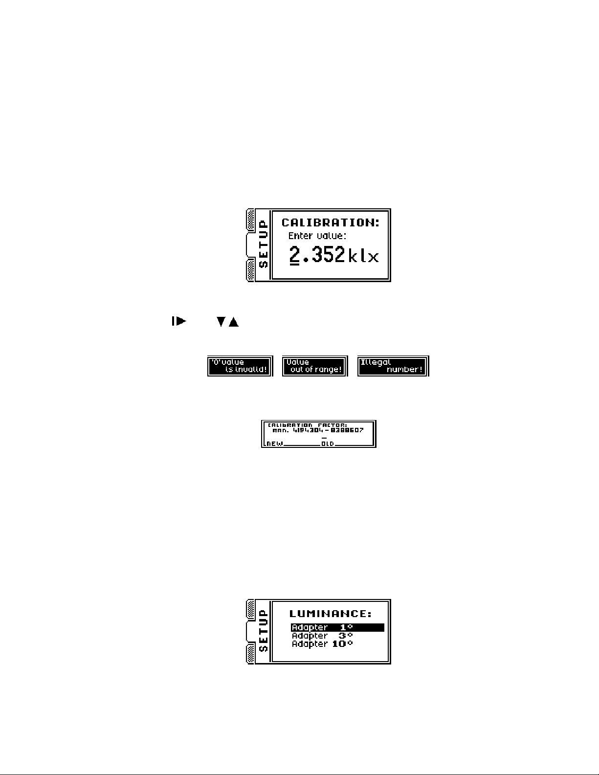
open. :
Value editing is allowed by inputing values from alphanumerical keyboard. Position of cursor can be
changed by key . Keys change multiplication factor of unit. Approving reference value can be
made by key „Calibration” available through hole in left lateral of steer unit (Illustration 1.). If inputed
value does not fit instrument criteria, meter will generate one of following error communicates:
New proper calibration ratio calculated based on measured one is saved in internal register of measure
probe. From main window of instrument last and actual calibration factor can be viewed only in the same
form that is saved in internal probe register:
The value of calibration ratio may include in range: 0.5÷1.0. In internal memory probe format that value
equals range: 4194304÷8388607.
Calibration can be done also in luminance mode. The Calibration factor is only one and it equal concerns
illumination and luminance measurements. This can be done because steer unit allows only proper display and calculation of various physical values.
5.1.2.4. Luminancja
Function: on/off luminance measurement mode.
It is necessary to connect (or disconnect) proper measure probe accessory. Type of connected accessory
can be chosen from expandable luminance menu:
Luminance mode can be set only for probes that are compatible witch luminance operation mode. In other
case instrument does not allow setup that option.
For luminance option all types of instrument operations are available. Besides all setup option, integral
values and statistics are memorized. That option allow to continue measures when switching from illumination to luminance mode and vice versa.
– 12 –
Page 13
5.1.2.5. Backlight
Function: on/off back light of display.
Display back light increase contrast of lcd, through that increase reading capabilities of lcd screen, but
when it's on it decrease battery life time. Back light increase brightness of display, when measure is supplied from battery that option allow reading display at dark rooms and is not noticeable at normal illumination. When back light driver is on it increase battery power consumption for about 25%. Instrument by
default increase battery life time by switching back light driver of when instrument is powering on. Lcd
back light can be on for a moment by specific key placed on left side of lateral steer unit (Illustration 1.).
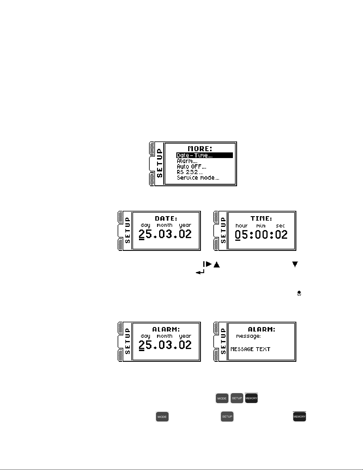
5.1.2.6. More...
Function: sub menu for calendar setup, alarm, automatic power off, parameters of PC data transmission :
Date-Time...
- real time clock setup. New windows will open sequentially:
Alarm...
Setup values is done by the alphanumeric keyboard keys. Position of cursor can be
changed in right direction by keys , and in left direction by key . Approv-
ing setup values is done by key .
- on/off alarm. This option can be used for example to remind about date of certify
(calibration). When alarm is active (signalized by icon in status stripe: ), during
startup of instrument window with alarm communicate will appear if date will be
equal or greater then setup alarm date value. After switching alarm option on new
windows will open sequentially:
Editing date value is done like edit process of real time clock setup. During alarm
communicate edit process, directly from keyboard alphanumeric keys are available
base chars (digits, dot and space). With all keys additionally user can input three
different chars that are placed at left part of key. Switching through different key
functions take here menu choice keys: , that background color is
same as input special chars. So to enter char from upper level of special chars user
must push key , from middle level and from bottom level before
pressing keyboard alphanumeric key.
If menu choice key was used again it cause switch to entering base chars mode.
– 13 –
Page 14
Auto off...
Shape of cursor decides about selected sort of input char : - base char, - upper
level characters, - middle level characters, - bottom level characters. Cursor
position can be shift right by key's , and shift left by key . Approving
setup values can be done by key .
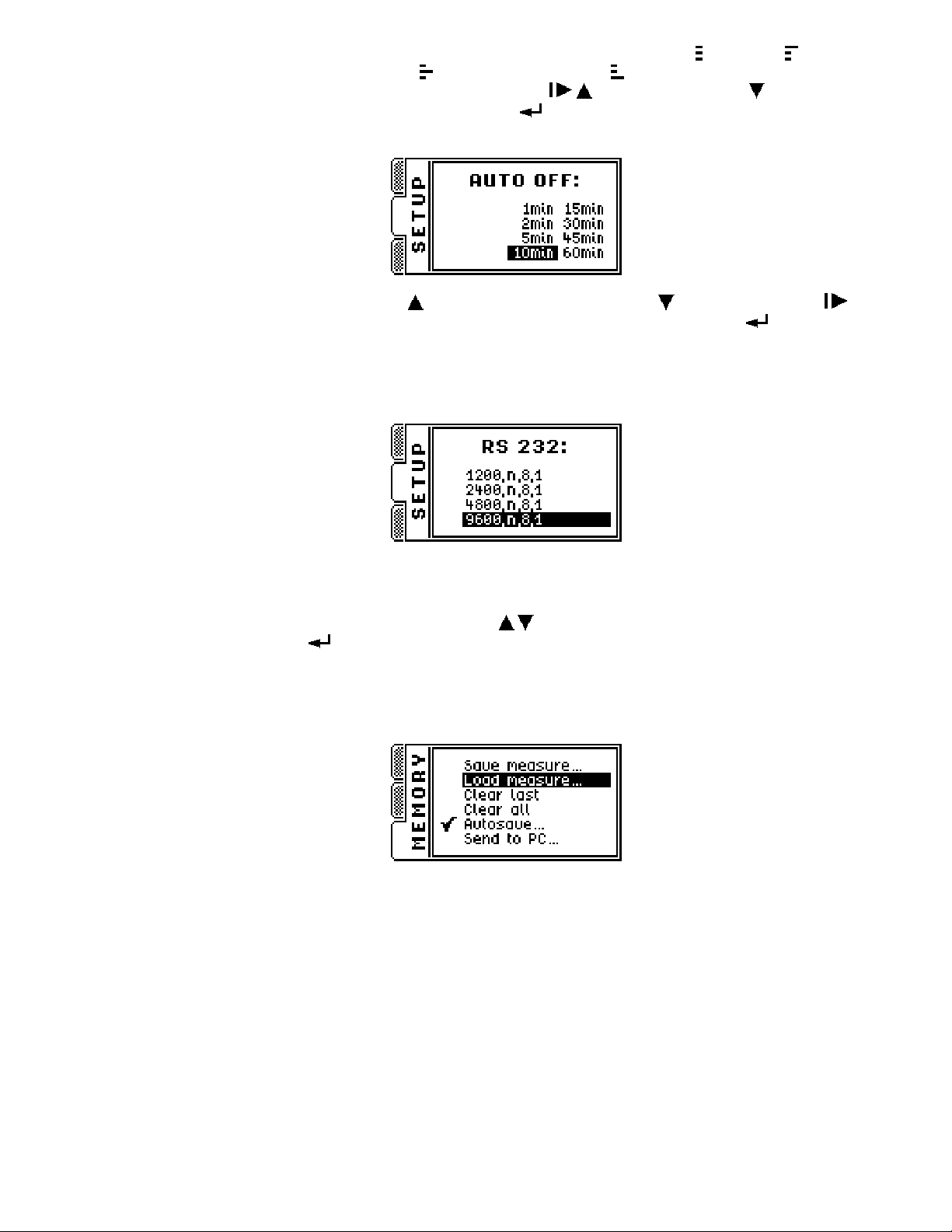
- inactive time setup for auto off mode. After selecting new window will open :
Keyboard key shift pointer to previous position, to next position, and
shift among columns. Approving setup values can be done by key . This setup
window set's time interval that must elapse from last key press to automatic power
off instrument. This time is counted only if instrument is on PAUSE mode.
Automatic power off is used for increase battery life time.
RS 232... - RS 232 data transfer parameters setup. After select new window will open:
Menu contain in sequence : baud rate speed, parity control, amount of data bit's and
amount of stop bit's. As can be seen user can only change baud rate data speed. Selection can be done by key's and approving setup values can be done by key
.
Service mode...
- This option is used in preinitialize process of instrument by manufacturer. It
shouldn't be turn on by user.
5.1.3. MEMORY
Illustration 5. Bookmark MEMORY with auto save option selected .
5.1.3.1. Save measure...
Function: Saving last measure into first free memory cell.
After selecting, new window with save cell number and comment will appear (max 512 save cells for internal memory and 511 for external memory):
– 14 –
Page 15
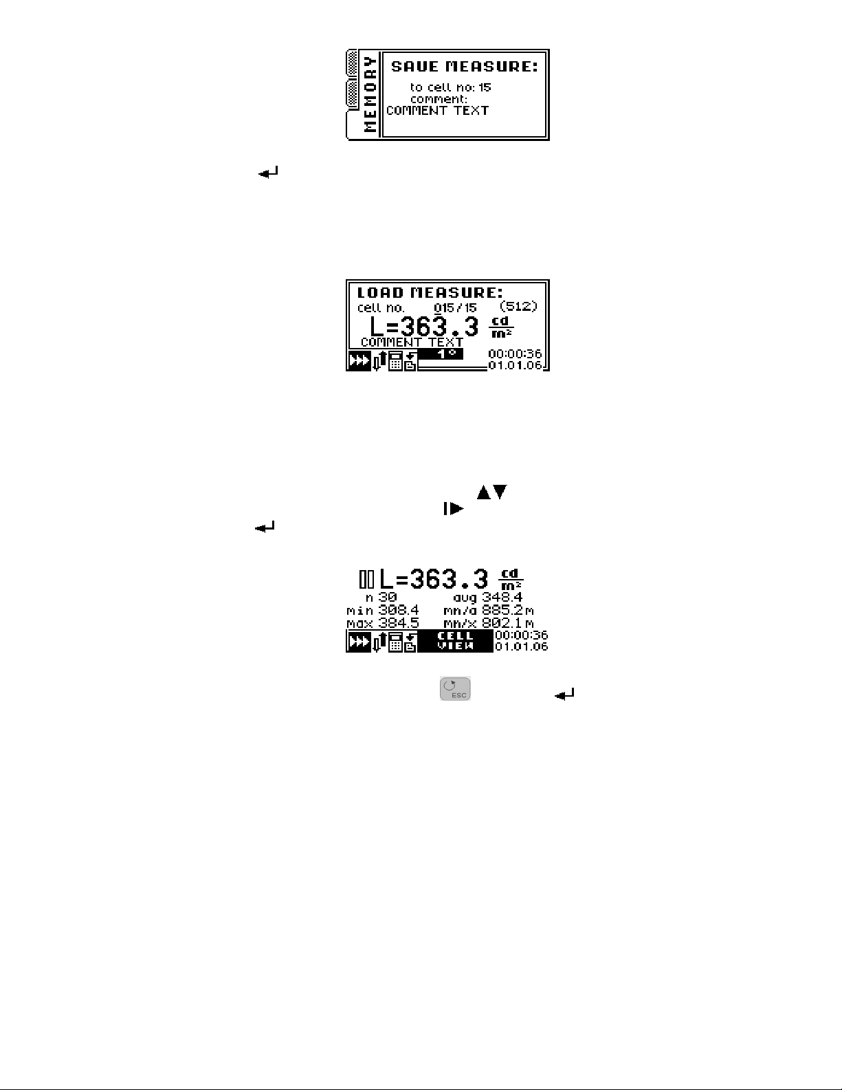
Editing Comment can be done just like editing Alarm comment in menu SETUP. Approving setup values
can be done by key .
5.1.3.2. Load measure...
Function: Browsing memory content.
After selecting, new window with measure saved in cell will appear:
Illustration 6. Window with measure saved in cell.
In window instrument prints: number of actual printed cell, number of occupied cell, measure physical
unit, value of measure, user comment, shortened status that signs instrument setup during measure, date
and time of measure and in case of luminance measurement type of external accessory used during measure (measure field angle accessory).
By default instrument prints last saved cell. Editing number of browsing cell is done by keyboard alphanumeric keys by entering suitable cell number or by keys increasing or decreasing number of actual
selected cell. Cursor position change is done by key .
After pushing key new window with memory cell data explorer will appear:
Illustration 7. Memory cell explorer.
User can return to cell list window by pushing key , pushing key will rewrite content of printed
cell to measure window of instrument. Measure options and saved instrument setup during rewriting will
be programed into instrument. This option allow in easy way to continue saved measure. However meter
forbids rewriting luminance measure when instrument is not in that measure mode. Also meter forbids
rewriting illumination measure when instrument is in luminance mode. Steer unit forbids rewriting saved
measure that was made with different probes that actually is connected to the instrument ( concerns
RF-100
).
5.1.3.3. Clear last
Function: deleting after approving content of last memory cell.
5.1.3.4. Clear all
Function: deleting all cells after approving content of whole memory.
5.1.3.5. Autosave...
Function: on/off automatic save measures into memory.
After selecting, new window with auto save time will appear :
– 15 –
Page 16
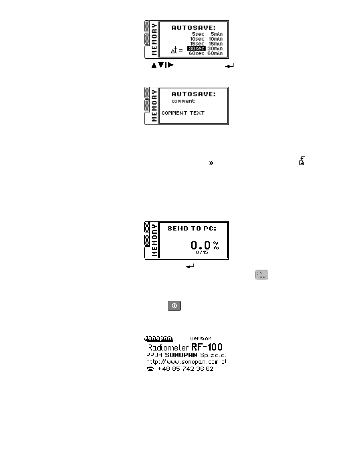
Time values change is done by key's and approve by key , after that new window with allow user to edit comment will appear. In this window user make default comment that instrument will
give for all cell's during auto save option enabled :
Process of editing comment is the same as in case of editing Alarm comment.
With auto save option enabled, instrument will switch in continuous measure mode. Instrument firmware
does not allow switching to single measure mode or switching from auto range mode during auto save
option enabled. After running measure, instrument will save result in setup delta time. During measure
instrument signalize auto save by blinking working state icon and by icon for memory auto save on
status stripe. After fill of all available memory cells, new window will appear witch communicate about
no free memory cell available and measure process will stop.
5.1.3.6. Send to PC...
Function: sending memory measure content to PC.
After selecting, new window will appear:
Transmission will start after pressing keyboard key . In lcd display user may see overall progress of
memory transmission. Transmission process can be broken through keyboard key .
5.2. Starting instrument (power on sequence)
To power on instrument user must press key . After pressing the power button screen displays starting winieta with manufacturer data and actual firmware version of meter, and after initializing
probe unit – version of measure probe firmware:
Illustration 8. Starting winieta of Radiometer-Photometer RF-100
At lower part of lcd display instrument prints progress bar of initialization task. After task is finished meter generate short sound signal that indicates it is ready to work. First screen can be closed by pressing
any keyboard key. If alarm was set and if alarm date condition is fulfill instrument will print communicate with date and text of communicate:
– 16 –
Page 17
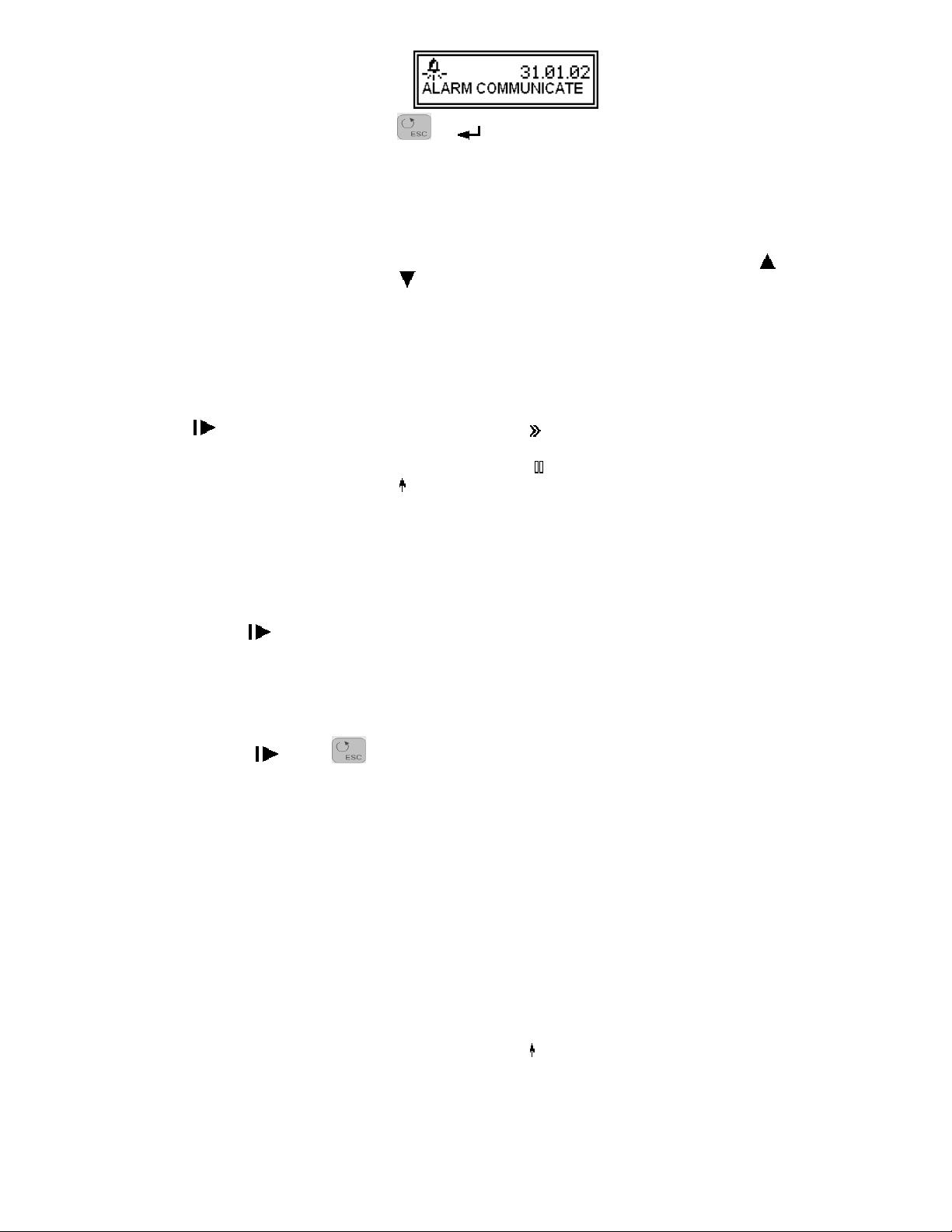
Alarm screen can be closed by key or . All instrument setups are initialized from saved values
generated during last power off sequence. Last statistics and integrals for illumination and luminance
measures also reinitialized. It also refers to entered comments values and positions of MENU pointer.
Instrument is in PAUSE mode.
5.3. Selecting measure range
Change of measure range can be made from main menu window (Illustration 2.) using key: - changing
to range grater then actual selected, - changing to range less then actual selected. Naturally when auto
range option is selected at measure process instrument will select optimal range automatically. In most
case scenarios automatic measure range is advised. Manual range switching was expected mainly for control goals.
5.4. Measure
Running measures is only allowed from main window (Illustration 2.). Measure is started through push
key . In display instrument prints MEASURE icon . Meter measures average value from one sec-
ond period of measure. Result is printed on display with four digits precision. After measure finished instrument change it's operation mode to PAUSE ( icon: ). If during measure instrument detect range
overflow it will print overflow icon before result value.
In case of selected measure mode, instrument run single or continuous measure .
5.4.1. Single measure
For that measure mode manual or automatic measure range change was expected. In single measure mode
instrument triggers only one measure period. In case when automatic range change option is selected,
measure stands from point when optimal measure range was selected.
Holding key cause continuous measure to point when key is released.
5.4.2. Continuous measure
Continuous measure always take place at automatic measure range change. This setup is controlled and
possibly corrected after switching instrument into continuous measure mode. Measure will continue until
keyboard key or key is pressed.
5.4.3. Relative measure
This option was expected mainly for visualize measured values in percents of any reference values (compare measures). At relative measure mode user may manually add illumination values to statistics also
statistics can be deleted.
5.4.4. Integrating
Integral illumination in respect of time called exposition hasn't got any main value on photometric
measurs. This option is expected for probes that measure radiation hazard, where time of exposure and
absorbed dose is fundamental. But yet, in case when variable illumination conditions and when user can't
exactly determine illumination value, user can use integral mode. Measure will be made until average
value of measure is stable and determined. Result of integrating measure is illumination value.
In case when in any measure period value of measured value is grater then highest measure range, before
integral value instrument will print range overflow icon: .
Setting integrating mode “on”, cause reinitializing earlier computed integral value and result connected
statistics. Also reseting device mode to measuring peek values (single, continuous measure mode) cause
reinitializing earlier saved statistic and give possibility to continue measure from last saved point. The
measure data that upper text is referring is independently memorized for luminance and illumination
modes, also after switching instrument off.
– 17 –
Page 18

During integrating mode it is possible to manually add measured peek values to illumination statistics and
deleting it's value is also possible.
5.4.5. Statistics
Statistics function operates on chosen measure values and make possible :
computing average value,
finding minimal value,
finding maximal value,
computing min/avg ratio,
computing min/max ratio.
Above-mentioned operations will be executed on measure values that user may manually or automatically
add to statistics (p. 5.1.1.6.
...
).
5.5. Measures memory
Radiometer-Photometer
RF-100
is provided with internal 32kB memory. Memory is used to storage results of measurement. Memory is divided into 512 cells. One cell can hold one measure. At writing process user may add comment to cell. Maximal comment size is 16 chars (it can be for example identifier of
measuring position ).
Every cell store:
•
date and time of measured,
•
comment,
• measured values,
•
sort of measure type (illumination, integral, luminance),
•
measurement physical unit,
•
all setup values of instrument from measure time,
•
measure probe identifier.
Firmware available memory exploring option, also it enable rewriting saved cell value into measure window of steer unit. All measure data and setup of device are then rewritten. After that, device setup and
measure data are the same as data and setup during measure save operation. This give possibility to continue measure from last saved point.
Writing data is only allowed to first free memory cell. When memory is full and at attempt of writing in-
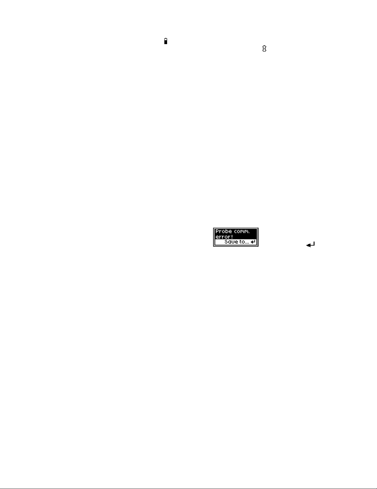
strument prints new window with communicate: . Deleting is only allowed for last cell
and for whole memory (all cells at once).
Measure data memory may by transfered to PC by RS-232C for storage or analysis purposes.
Besides that, instrument allows external memory connection. External memory have 511 storage cells.
Measure memory handling was described in paragraph 5.5.1. Błąd! Nie można odnaleźć źródła odsyła-
cza.. Błąd! Nie można odnaleźć źródła odsyłacza.
.
5.5.1. Working with external memory
External measure memory handling procedure is very easy. It only consider connection memory module
to proper steer unit socket (Illustration 1). From that moment all operations that will be selected from
menu MEMORY refer to connected external memory. Proper instrument operation is only provided with
SONOPAN external memory module type
MP32.RF-100
.
In order to connect or disconnect external memory it is necessary to switch off the instrument.
WARNING! It is forbidden to connect or disconnect external memory during data transmission
from meter to computer.
Data stored in internal and external memory do not need power supply.
5.6. Working with luminance accessory
In order to connect luminance accessory it's necessary to unscrew ring from measure probe receipt field
and then on it's place screw luminance accessory (Illustration 9):
– 18 –
Page 19
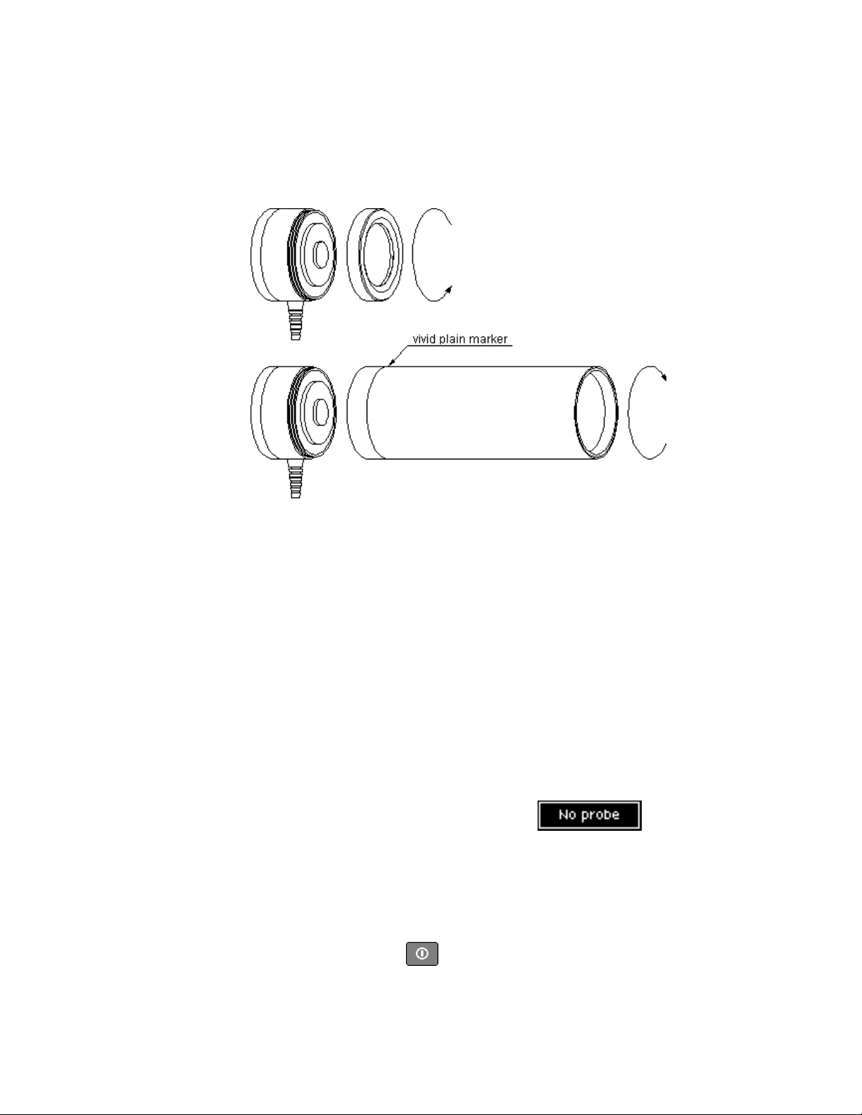
Illustration 9. Connecting luminance accessory.
In next step user must change instrument mode to luminance measure. (p. 5.1.2.4.
necessary to pay special attention to proper select measure field angle value in meter equal to adopted
accessory. This has fundamental meaning when computing luminance signal measured through probe.
Proper instrument results are only provided with SONOPAN accessory's, since accessory is structurally
fitted to the algorithm of the program that recast luminance signal at probe receipt filed to luminance
units.
When returning from luminance to illumination measure typed, it is necessary to screw earlier disconnected ring. This warrants proper probe direction characteristic.
5.7. Working without measure probe
During initiation process steer unit checks up the presence of probe unit. Instrument initialize probe unit
and read it's parameters (type of head, probe firmware version, count and values of measure ranges, type
of measure unit value, compatibility witch luminance mode) and then check up it's authorization to work
with probe. When measure probe unit is not present or instrument is not authorized to work with it, after
closing starting winieta new window witch statement will appear : and at status bar,
meter will do not display range of measure. Starting new measure is forbidden, but options : memory
exploring, transmission memory data to computer also options that are not related witch measure and
reading parameters from measure probe are available.
ter switching instrument off.
5.8. Switching instrument off
Measure probe unit must by connected only af-
Luminancja
). It is
Instrument can be switched off only by key . During power off sequence device will save setup values, computed integral and statistic values, comments, positions of menu pointers, external memory
pointer and luminance mode status on internal static memory. Save procedure will not execute when device will be switched off by battery extraction. Data maintenance in earlier described memory doesn't
require powering the source.
– 19 –
Page 20

6. COMMUNICATION WITH PC
Connecting meter
RF-100
to computer is realized through RS-232C and cable provided together with the
device. Placement of data socket reveal Illustration 1.
6.1. Transmission protocol
Serial data line transmission parameters:
•
1200÷9600bds,
•
8 data bits,
• 1 start bit,
•
1 stop bit,
•
no parity bit.
Communication between computer and instrument is bidirectional, i.e. meter sends data and also can be
controlled by PC.
6.2. Automatic power on
With connected meter
RF-100
to computer automatic power on will take place at first occurrence of data
frame send by computer through RS-232C port. It allow for full attendance of outlying meter from position of steering. When automatic power off after programed idle time occurred. It's recommended to detach transmission cable when functioning with the computer isn't expected. It will help avoid uncontrolled
instrument activations.
6.3. Controlling computer program
Manufacturer to purchased meter
RF-100
supply computer program
RF.exe
. After connecting instrument
to computer and starting meter, it's necessary to proper configure serial transmission port (setup number
of serial port corresponded with meter connection socket and setup data line speed, same as setup in instrument). Program permits fully control of instrument and reception of measure data content. Besides
that history option is available user may search measure in history of stored measures with different mask
(15 different search criteria). meter data, history and results can be saved on hard disk in text format (human-friendly) approbate by any spreadsheet application. Hear separate chars are tabulation chars. It allows for optional processing measured data into prepared spreadsheet template.
Besides that, SONOPAN offer for interested customers that require independent computer software programming of instrument Delphi components in the form of compiled software :
• for handling serial port transmission and conversion of transfered data,
•
for controling instrument (like upper plus user interface).
Important assistance in work over own application can be bookmark „BuforCOM” in program
RF.exe
(it
prints received and sent chars and make possible their interpretation).
For further information please contact manufacturer.
7. POWERING
Radiometer-Photometer
RF-100
is powered through single 9V battery. It is recommend to use so-called
alkaline batteries witch big capacity of the 6LR61 type or similar. They assure 20 hours of noninterrupted instrument work. Container for battery is placed on back side of instrument unit.
– 20 –
Page 21
7.1. Control of battery supply.
When instrument is operating, condition of battery supply is controlled. Battery supply level is printed by
means of battery condition level icon on status stripe. Filling supply rectangle icon is proportional to
battery voltage value. When power source is exhausted, icon will look like: . Then battery must be replaced with new one. In other case instrument will power off automatically after detecting transgression
critical supply voltage.
7.2. Automatyczne wyłączanie.
Radiometer-Photometer
RF-100
was equipped with two automatic power off units. First one turns off the
meter when supply voltage is lower then critical. Second one shuts off instrument after programed idle
time event occur.
The idle time is counted from last point in time when any key was pressed or point in time when measure
is finished.
8. EXPLOITATION RECOMMENDATION
•
It's forbidden to expose instrument on falls, shakes neither on any other factors that might produce
mechanistically damages.
•
The protection of measurement probe should be removed only for duration of the measurement, protecting the optical element of the field of the receipt against the smudge of dirt.
•
In case when overflow range occur on the highest measure range it's recommended to remove probe
from measure field or shield it from high radiation. Long exposition in high radiation may damage
measure probe .
• It's forbidden to connect or disconnect measure probe unit during instrument operation.
•
In case when new window with communicate opens: user may use key in case
when save last result to device memory is required. Next step consider switching off / on of the instrument for new reinit probe process.
• Optical element of measure probe can be cleaned with soft material damped with clean alcohol.
•
Object-glass luminance accessory can be cleaned from dust by small soft clean brush or stream of
compressed air. Product in spray that operate similar to compressed air use with caution. They must
be kept vertical during the cleaning process .
• User should hold the glass element of the luminance accessory's in absolute cleanness from the side
of attached measuring probe, because the possible smudge of dirt has influence on values of the
measurement. Cleaning process is like in the case of the measuring head cleaning.
•
It's necessary to protect instrument from wet and aggressive chemical factors that can destroy instrument elements.
•
It's forbidden to remove features that secure access to calibration key (Illustration 1).
•
It's forbidden to connect into instrument sockets different devices, for which they stayed predicted.
• Instrument should be kept and transported in factory container.
•
In case of longer storage user should take the battery out from the device .
9. WARRANTY AND REPAIRS
Radiometer-Photometer
RF-100
is shipped with one year warranty from day of purchase. It does not require special exploitation exceptions excluding exploitation recommendations manufacturer's warning
signs.
– 21 –
Page 22

All sort of repairs are achieved by manufacturer.
– 22 –
Page 23

10. CE MARKING AND EEE DIRECTIVE
Product described in instruction fulfill European Union command paper stipulations :
89/336/EEC Electromagnetic compability.
Meeting above requirements is
confirmed by CE sign.
This product can't by treated like waste of the household. Product should be
handed over to the right rallying point of the used up electrical and electronic
equipment.
– 23 –
Page 24
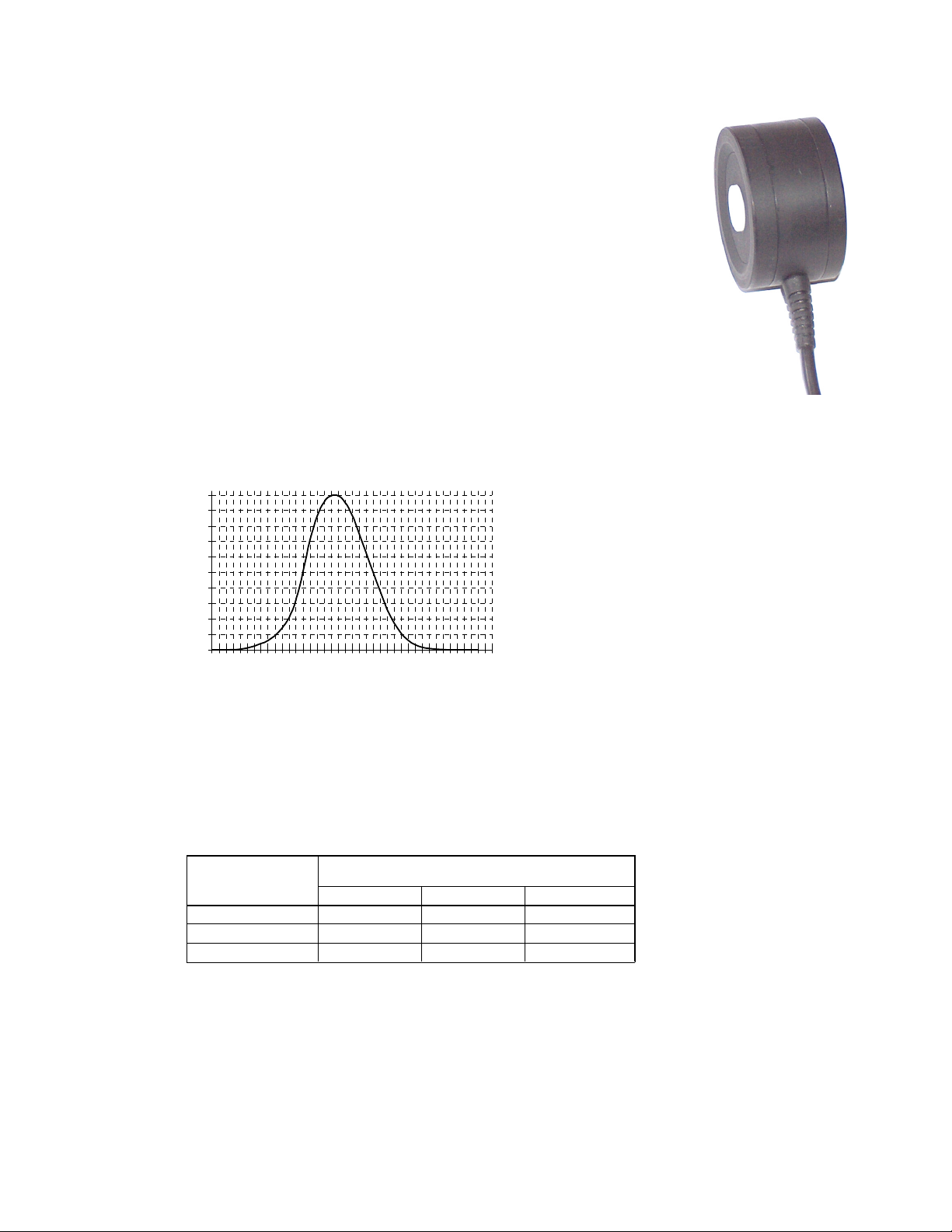
11. APPENDIX A: Photometric probe G.L-100
Photometric probe
RF-100
. It has possibility to connect additional accessory for measuring lumi-
G.L-100
is adapted to operate witch instrument type
nance value. It comes with basic luxmeter
of radiometer-photometer
RF-100
. It is designed for measure natural and artifi-
L-100
equipment and extra equipment
L-100
or
cial luminance and after connecting proper accessory for measure the illumination. With steer unit it makes basic photometric tool guided to all kinds of metro
logic staff and optical radiation laboratory employees. Very big dynamics of
measure system make possible wide usage range.
Photometric measure probe
•
radiation detector directional and spectrum corrected,
• data converter (analog - digital),
• zero setting driver,
• auto zero setting driver,
• automatic range change unit,
•
calibrate value register,
•
communication interface with instrument (steer unit).
G.L-100
make complete photometer including:
1,0
0,9
0,8
0,7
0,6
0,5
0,4
0,3
0,2
0,1
0,0
380
400
420
440
460
480
500
520
540
560
580
600
620
640
660
680
700
720
740
760
λ
[nm]
Relative visible spectrum sensitiveness of measure probe type G.L-100.
TECHNICAL DATA:
•
Precision class: A according to CIE
• Entire error: ≤ 2,5% ±1LSB (for iluminant A)
• Spectral matching: f
• Direction matching: f
• Measuring ranges:
E [lx]
’ ≤ 2% (CIE)
1
≤ 1,5% (CIE)
2
L [cd/m2]
1° 3° 10°
0,001 ÷ 30 0,1 ÷ 12k 0,01 ÷ 1,2k 0,001 ÷ 120
0,1 ÷ 3000 10 ÷ 1,2M 1 ÷ 120k 0,1 ÷ 12k
10 ÷ 300 000 1k ÷ 120M 100 ÷ 12M 10 ÷ 1,2M
• Detector: Silicon photo diode spectral corrected to V(λ) (CIE)
• Dimensions Ø44 × 25,5mm
• Operation temperature 0 ÷ 40ºC
• Max environment relative humidity ≤ 80%
•
Length of connection cable 1,5m
– 24 –
Page 25
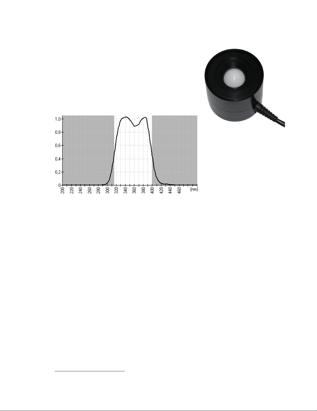
12. APPENDIX B: Instrument probe for measure ultraviolet irradiance UV-A
G.UVA-100
G.UVA-100
unit type
•
radiation detector directional and spectrum corrected,
•
analog to digital converter,
measuring probe is adopted to cooperate with steer
RF-100
. It makes complete radiometer including:
• zero setting driver,
•
auto zero setting driver,
•
automatic range change unit,
• calibrate value register,
communication interface with instrument (steer unit).
Relative spectrum sensitiveness of measure probe type G.UVA-100.
TECHNICAL DATA:
•
Spectral range:
•
Spectral matching f'1 *): ≤ 20%
•
Direction matching f
• Measurement ranges: 3 W·m–2 with resolution 100 µW·m–2
•
Dimensions: Ø44 × 39.5mm
• Operating temperature range: 0 – 40ºC
•
Relative humidity:
•
Length of connection cable: 1.5m
INTENDED USE:
1. Measurement of ultraviolet irradiance in the UV-A range.
2. Assessment of personal exposures to non-laser optical radiation in accordance with:
•
Directive 2006/25/EC.
•
EN 14255-1:2005.
∆λ
315 – 400nm
0,5
∆λ
305 – 410nm
0,1
*)
: ≤ 2%
2
300 W·m–2 with resolution 10 mW· m–2
30 000 W·m–2 with resolution 1 W·m–2
≤
80%
*
Characterizing the Performance of Integral Measuring UV-Meters. Final Report of WG1 Thematic
Network for Ultraviolet Measurements. November 2000.
– 25 –
Page 26
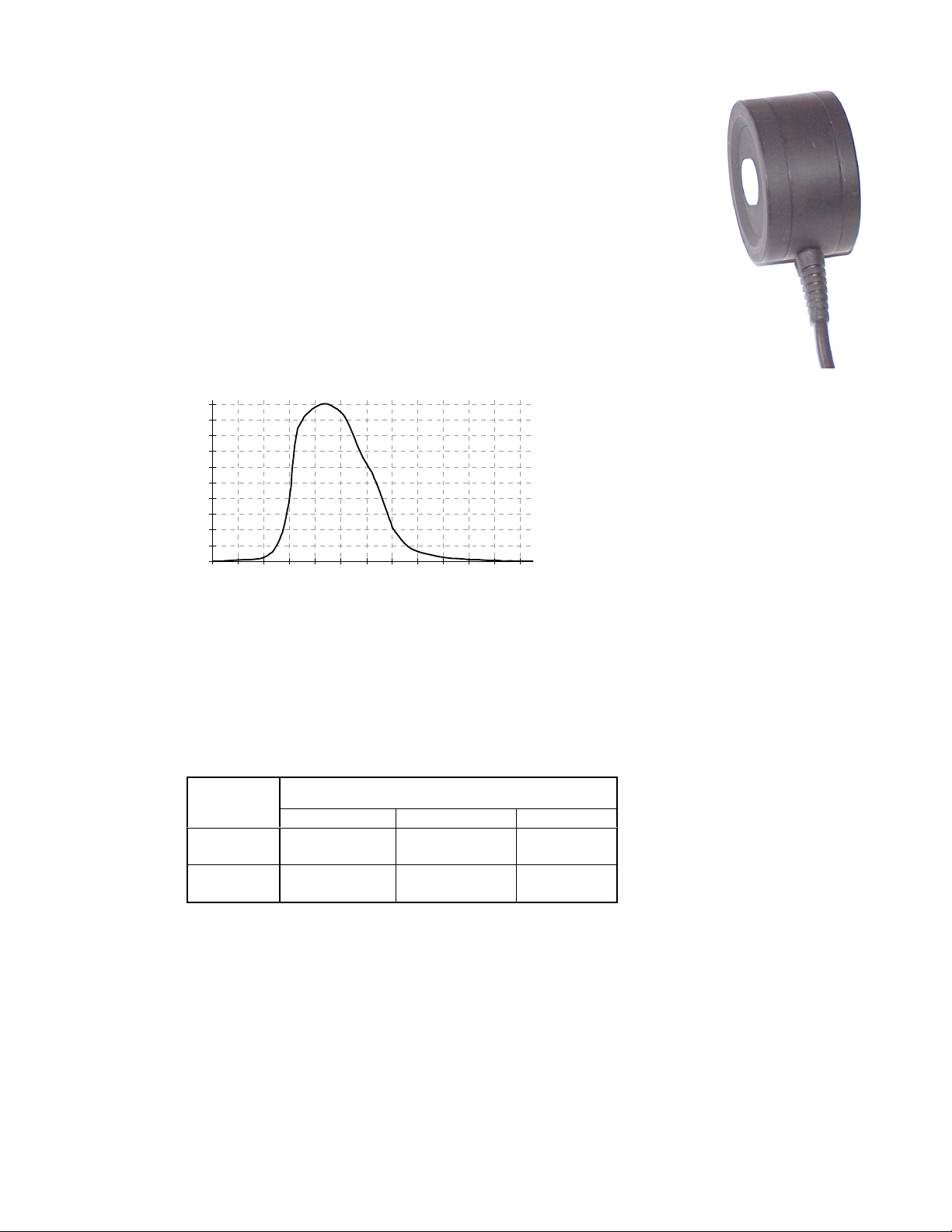
13. APPENDIX C: Instrument probe to measure photochemical
(blue light) retinal hazard
G.BLH-100
Measurement probe
RF-100
. Instrument probe is designed for measure photochemical (blue light) haz-
G.BLH-100
is adopted to cooperate witch steer unit type
ard intensity that causes chemical changes in retina, and after connecting proper
accessory for measure energetic luminance that kind of radiation spectrum.
Measure probe
• radiation detector directional and spectrum corrected,
• data converter (analog - digital),
• zero setting driver,
• auto zero setting driver,
•
automatic range change unit,
• calibrate value
• communication interface with instrument (steer unit).
1,0
0,9
0,8
0,7
0,6
0,5
0,4
0,3
0,2
0,1
0,0
350
G.BLH-100
register,
370
390
make complete photometer including:
410
430
450
470
490
510
530
λ
550
570
[nm]
Relative spectrum sensitiveness of measure probe type G.BLH-100.
TECHNICAL DATA:
• Entire error:
• Spectral matching: B
• Direction matching: cosinus; f
•
Measuring ranges:
≤
2,5% ±1LSB
wg ICNIRP
λ
≤ 1,5% (CIE)
2
(irradiation intensity and energetic luminance with accessory's 1°, 3°, 10°):
E [W·m–2]
L [W·m
–2
·sr–1]
1° 3° 10°
10×10–6 ÷
0,3
1×10⁻³ ÷ 30
•
Detector: high stable photodiode
• Dimensions: Ø44 × 25,5mm
• Operation temperature: 0 ÷ 40ºC
• Max environment relative humidity:
• Length of connection cable: 1,5m
1×10⁻³ ÷
120
0,1 ÷
3
12×10
0,1×10⁻³ ÷
12
10×10–3 ÷
3
1,2×10
≤
80%
10×10–6 ÷
1,2
1×10⁻³ ÷
120
INTENDED USE:
Assessment of personal exposures to non-laser optical radiation in accordance with:
•
Directive 2006/25/EC.
• EN 14255-1:2005.
– 26 –
Page 27
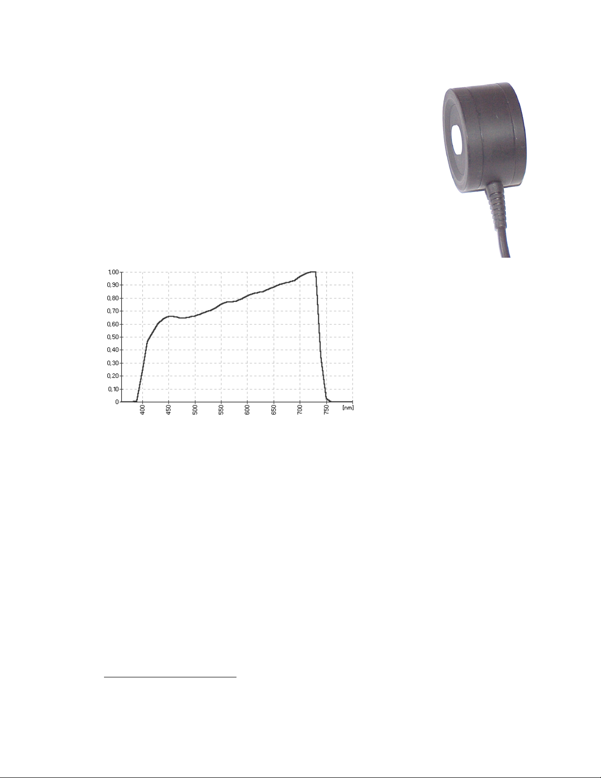
14. APPENDIX D: Instrument probe to measure photosynthetic active
radiation
G.PAR-100
Measurement probe
RF-100
. Device is quantum detector designed for measure irradiation intensity
G.PAR-100
is adopted to cooperate with steer unit type
that causes photosynthesis process in green parts of plants (PAR radiation*).
Measured by probe values together witch instrument integration mode allow
measure dose of PAR radiation that is reaching growing.
Measure probe
• radiation detector directional and spectrum corrected,
• data converter (analog - digital),
•
zero setting driver,
• auto zero setting driver,
• automatic range change unit,
• calibrate value register,
• communication interface with instrument (steer unit).
G.PAR-100
make complete photometer including:
Relative spectrum sensitiveness of measure probe type G.PAR-100.
TECHNICAL DATA:
• Entire error: ≤ 2,5% ±1LSB
• Spectral matching: relation photon-electron
• Direction matching: cosinus; f
•
Measuring ranges: 0,1 ×10⁻⁹÷ 3 ×10⁻⁶ E⋅m
10 ×10–9÷ 300 ×10–6 E⋅m-2⋅s-1 (0,01÷300 µmol⋅m–2⋅s–1)
1 ×10⁻⁶÷ 30 ×10–3 E⋅m
• Detector: high stable photodiode
•
Dimensions Ø44 × 25,5mm
• Operation temperature 0 ÷ 40ºC
• Max environment relative humidity
• Length of connection cable 1,5m
≤
80%
≤ 1,5% (CIE)
2
-2
⋅
s-1 (0,0001÷3 µmol⋅m
-2
⋅
s-1 (1÷30000 µmol⋅m
–2
⋅
s–1)
–2
⋅
s–1)
*
PAR Radiation (Photosynthetically Active Radiation): optical radiation, under it's influence plants photosynthesis
occur. Efficiency of photosynthesis is proportional to observed quantity of photons, and it is independent from correspond ded
photons energy. Detector that measure PAR radiation is called quantum detector. Instrument that is equipped with that detector is
called fitophotometer or quantum radiometer. Unit of photon flux density used if w photobiology is E⋅m–2⋅s–1 (Einstein by meter
square by second). Equivalent unit in SI system is mol⋅m
–2
s–1 (mol by meter square by second).
⋅
– 27 –
Page 28
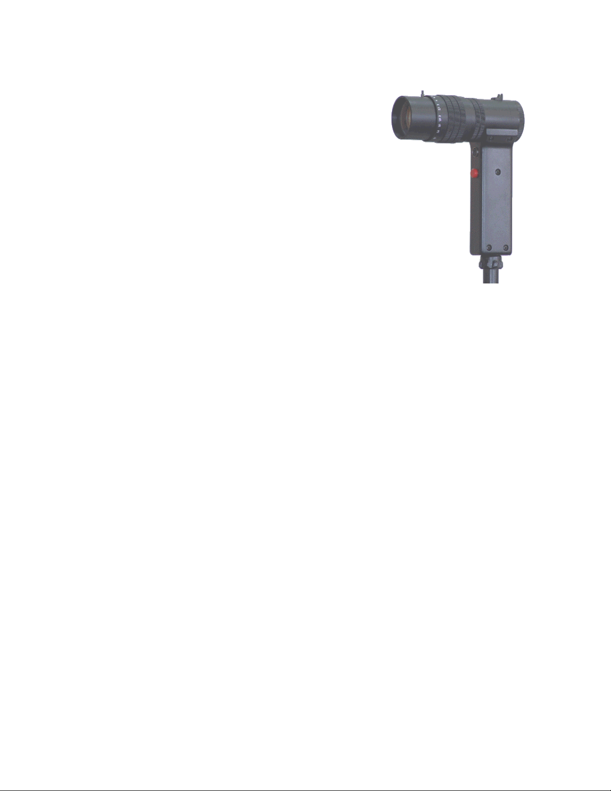
15. APPENDIX E: Luminance accessory PL1.-RF100
Accessory
into luminance one. It makes extra equipment of luxmeter
or radiometer-photometer
PL1.RF-100
is device that change illumination meter
L-100
RF-100
. Probe is guided to cooperation with all measure probes that consider luminance measure mode (for example. G.L-100, G.BLH-100 e.t.c.). Operating
complexity and low price make alternative solution for more expensive classic luminance meters .
After installing on measure probe accessory
PL1.RF-100
and
selecting from instrument menu luminance mode, meter directly
displays value and unit of measured value (cd· m–2, W·m–2·sr–1).
Measure may be triggered from instrument or directly from luminance accessory after connecting it with meter through suitable cable.
TECHNICAL DATA:
•
Measure field angle: 1°
•
Lens : 100mm, ≤ f/2,5
• Calibration error: ±1% (relative to probe)
•
View-finder : „back-sight” type.
•
Possibility to attach on typical photographic stand.
• Remaining parameters relative from measure probe, publi-
cize on it's specification.
– 28 –
Page 29
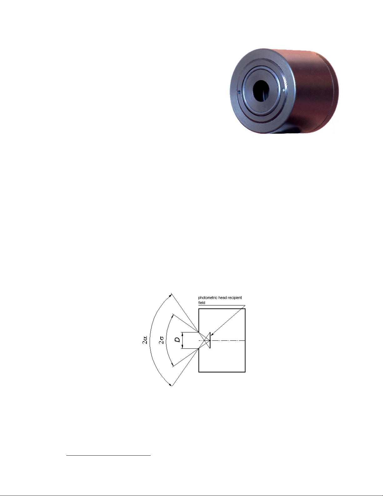
16. APPENDIX F: Accessory PL-68
to measure luminance with luxmeter instrument
Accessory PL-68 is simple device that allow measure luminance of spontaneously shining surfaces using luxmeter. It
is designed to co-operate with photometric probes of
SONOPAN illumination meters. Together with mounted
probe it make luminance meter. Conditions of correct
measure is even light flux draftage of analyzed surface in
the scope of boundary measuring angle (look TECHNICAL
DATA), homogeneous luminance (brightness) measured
field*) and cohere accessory reception field to object (It's
not allowed to measure from distance).
Accessory have adjust possibility, that allow to separate calibration of accessory-luxmeter kit.
Together with adopted luxmeter fit for negatoscope luminance measure, television screens, monitor
screens, diffusion lamp holder fields e.t.c.
After installing accessory PL-68 on photometric probe and attaching it to examination field, values signalized by luxmeter in lux units are luminance values measured in cd/m2 units.
TECHNICAL DATA:
• Entrance pupil D = 12,5mm (Illustration 1.)
•
Aperture angle – measure angled field : 2σ = 68° (Illustration 1.)
•
Boundary measuring angle 2α = 107° (Illustration 1.)
• Measure range in [cd/m2] like adopted luxmeter in [lx].
Illustration 1. Accessory PL-68 schema
*
Visual rate of luminance homogeneity measured field is sufficient.
– 29 –
 Loading...