

Page 1
1
Sonoma CGR30
Natural Gas Conversion Instructions
8
6
3
7
2
9
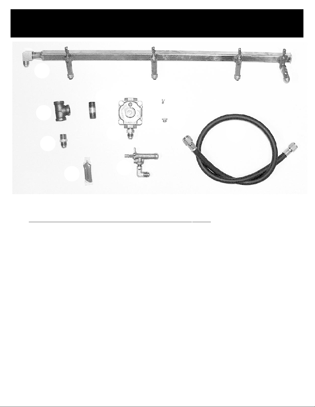
PARTS NEEDED FOR CONVER
Number Description
1 30" NG Manifold
ner valve
2 NG side b
3 NG Regulator
4 Rear I/R NG orifice
4 Rear I/R NG orifice
5
5 Side burner NG orifice 17000 BTU
6 3/8 x 3/8 x 3/8 T fitting
7
8 3/8 Nipple x 1 1/2
9 Pipe Joint Compound
10
Side b
Flared to 3/8 male pipe thread
Hose Assemb
ur
ner NG orifice 12000 BTU
ur
ly
TING FROM LP TO NG
5
4
10
Page 2
Sonoma CGR30
Natural Gas Conversion Instructions
Tools Needed:
Phillips head screwdriver
1/4” nut driver *
9/32” or 7mm nut driver *
Fig 1
Adjustable wrench
Be sure gas supply is off, the knobs are in the off
position and the grill is cool.
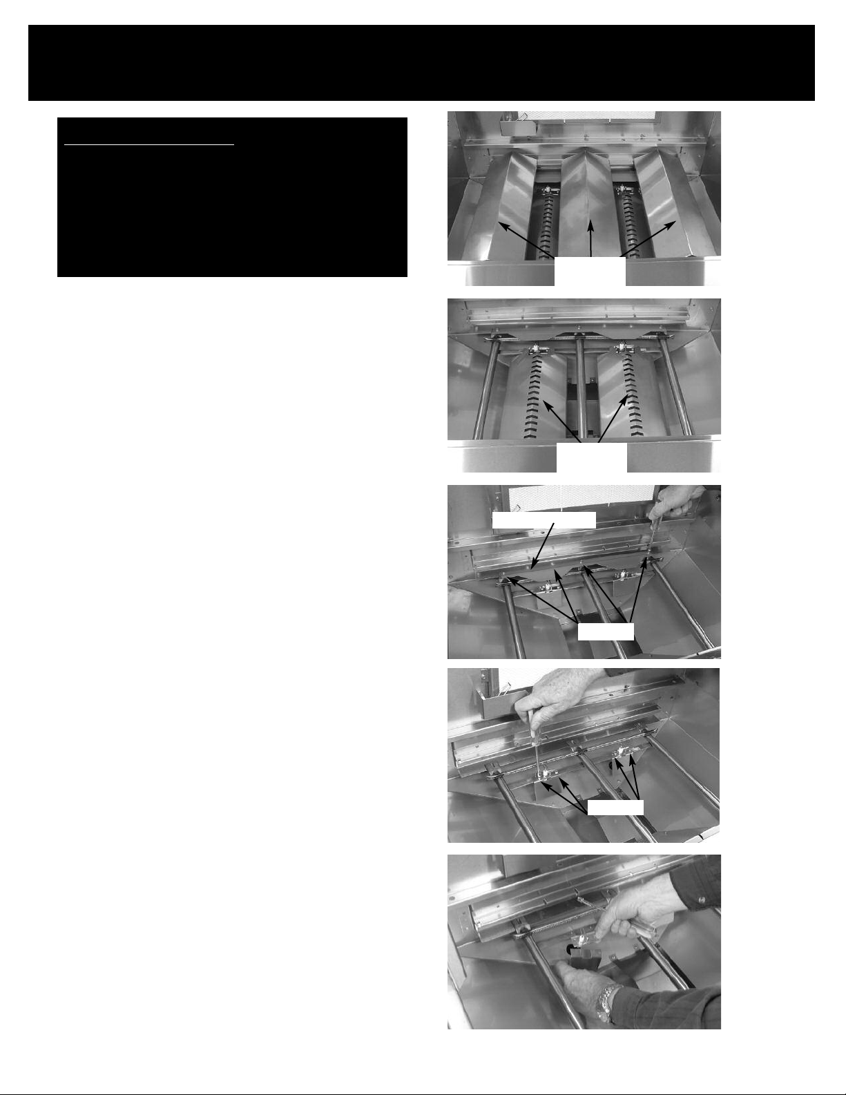
1. Remove cooking grates and top flavor grids (See
Fig. 1)
2. Remove bottom flavor grids (See Fig. 2)
3. Remove the screws holding the rear heat shield in
place. Lift out rear heat shield and set aside.
(See Fig. 3)
4. Remove the two screws holding each ignitor in
place. (See Fig. 4)
5. Lay ignitors on floor of grill. (See Fig. 5)
* 1/4” socket set with extension can also be used.
op Flavor
T
Grids
Bottom
Flavor Grids
Rear Heat Shield
Fig 2
Fig 3
Screws
Screws
Fig 4
Fig 5
Page 3
Sonoma CGR30
Natural Gas Conversion Instructions
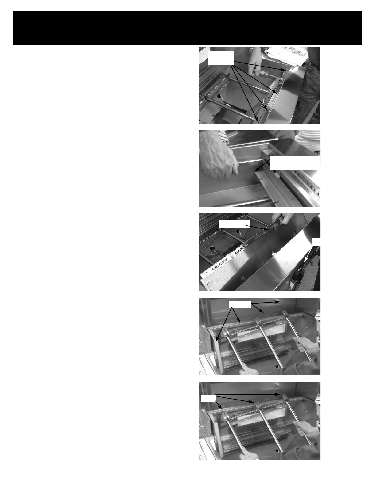
6. Loosen the six (6) screws at the top of the heat
shield, holding the front heat shield in place.
(See Fig. 6)
7. Loosen the bottom heat shield screws located
under the bottom lip of the heat shield. (there is
one screw on each side) (See Fig. 7)
8. Push the front heat shield towards the rear of the
grill. (See Fig. 8)
9. Grasp and push the burner(s) towards the rear of
the grill to detach the burner from the valves.
(See Fig. 9)
Note: You may have one or two burner assemblies, depending on your grill size.
crews
S
under lip
Bottom Screw
(Repeat on left side)
ig 6
F
Fig 7
10. Angle the burners up and pull out making sure
the tabs slide up through the cutout on the support channel at the rear of the grill. (See Fig. 10)
Heat Shield
Valves
Fig 8
Cutouts
Fig 9
T
abs
Fig 10
Page 4

Sonoma CGR30
Natural Gas Conversion Instructions
11. Fully remove the burners and front heat shield
from the grill body. (See Fig. 11)
Note: Be sure to hold onto the burners and
heat shield at the same time while
removing.
12. Remove the control knobs from the front of the
grill. (Use a pair of pliers with a cloth to avoid
any scratches or dents on the knobs) (See Fig. 12)
Note: Metal knobs on the 44” grill can be
removed by hand.
Fig 11
Fig 12
13. Remove both screws holding each bezel in place
on the control panel. (See Fig. 13)
14. Remove the bezels from the front control panel.
Screw
Fig 13
Bezels
Fig 14
Page 5

Sonoma CGR30
Natural Gas Conversion Instructions
(See Fig. 14)
15. Disconnect the left flex line from the manifold
using the adjustable wrench. This will free up the
left side of the manifold. (See Fig. 15 & 16)
16. Disconnect the right side flex line from the mani-
fold using the adjustable wrench. This will free
up the right side of the manifold. (See Fig. 17)
17. Remove manifold from grill body (See Fig. 18)
You are now ready to install the new
eft front
L
corner of grill
Flex Line
Fig 15
manifold
Flex Line
Fig 16
manifold
Flex Line
Gas Inlet Flex Line
Manifold
Fig 17
Fig 18
Page 6
Sonoma CGR30
Natural Gas Conversion Instructions
NG manifold.
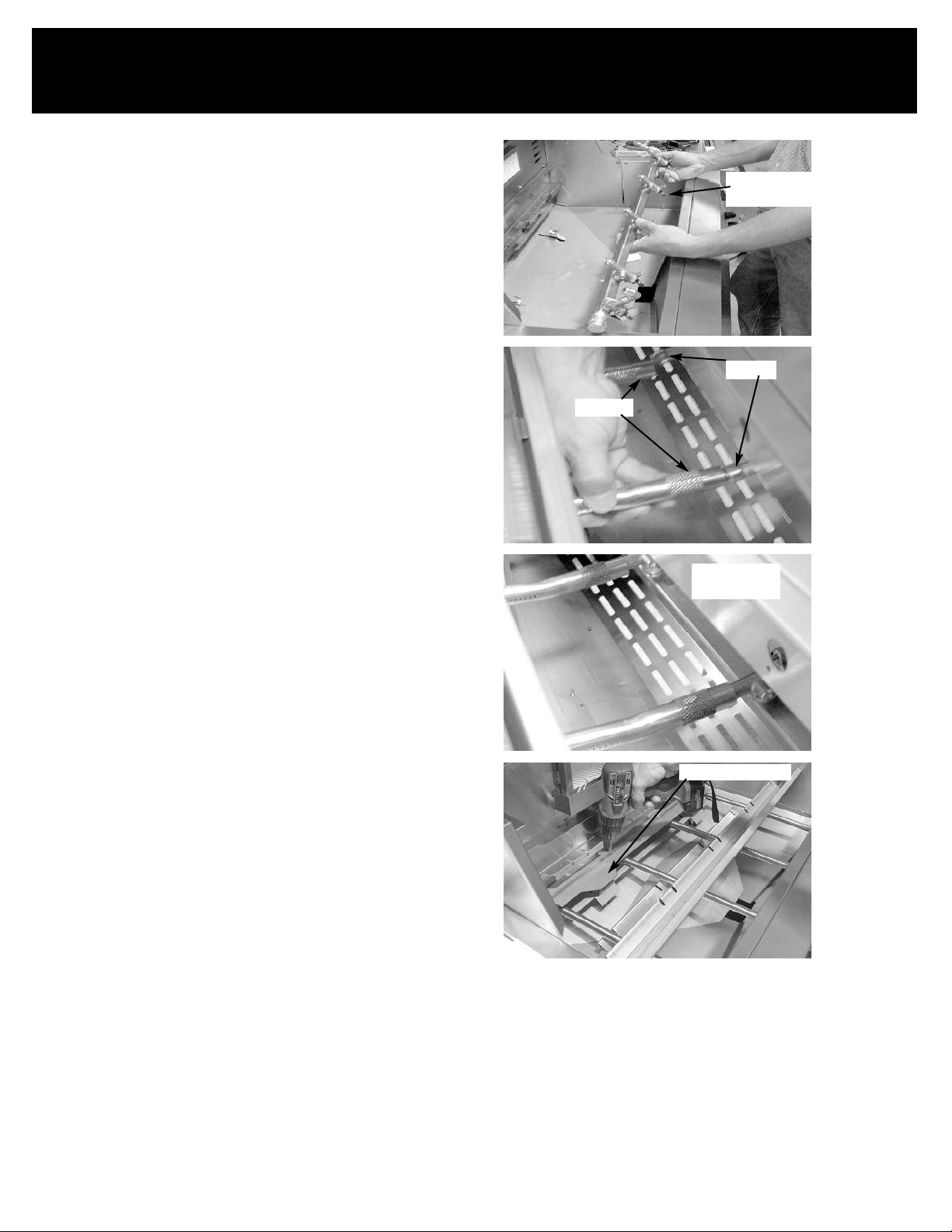
18. Start by placing the new manifold into the grill
body with the control knob stems going outward
through control panel front. (See Fig. 19)
19. Reattach the flex lines on the right and left sides
of the grill to the new manifold using the
adjustable wrench. (See Fig 17 & 15, on
previous page)
Control Knob
Stems
Fig 19
20. Reattach the bezels to the manifold with the
single screw on each one. (See Fig. 14 & 13)
21. Reattach the control knobs onto the manifold
stems, making sure “OFF” is facing upwards.
(See Fig. 12)
22. Place burners and front heat shield back into the
grill body, making sure the burner tabs fall downward through cutouts. (See Fig. 11 & 10)
23. Line up the burners with the valv
es on the mani-
fold, making sure they are level. (See Fig. 20 &
21)
24. Reattach the ignitors and their heat shields,
removed in step four (4), to the burners.
(See Fig. 4, on page 1)
25. Reattach the rear heat shield before attaching
the front heat shield to be sure the burners
remain over the valves. (See Fig. 22)
Valves
Burners
Fig 20
Burners fully
over valves
Fig 21
Rear Heat Shield
Fig 22
26. At the completion of the conversion, a leak test
should be performed on all fittings. See Use and
Care manual for leak testing procedure.
27. Proceed with reattaching the front heat shield
(See Fig. 6, 7 & 8 on page 2)
28. Reinstall the bottom and top flavor grids. (See
Fig. 1 & 2, on page 1)
29. Reinstall the cooking grates
Page 7
Sonoma CGR30
Natural Gas Conversion Instructions
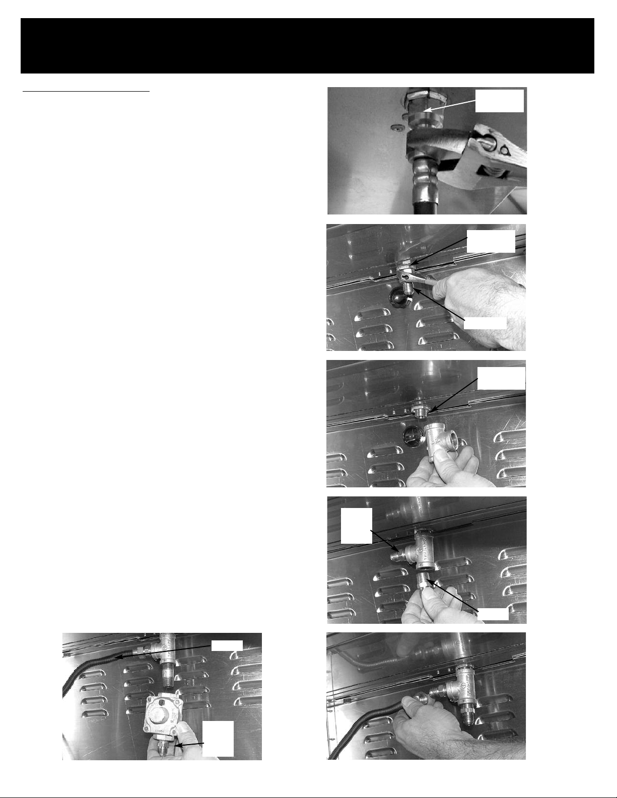
Installing the NG regulator
1. Remove the LP regulator from the main gas pipe using an
djustable wrench. Located inside the cart on bottom of grill
a
head. (See Fig. 23)
Remaining end still connected will be removed later.
2. Remove the brass fitting from main gas line. (See Fig. 24)
** Note – for the following steps, the supplied pipe dope
needs to be applied to all indicated fittings before the
fittings are screwed in.
Pipe dope should not be used on any flared fittings!
3. Attach the “T” fitting to the main gas line as shown. Tighten
with wrench. (See Fig. 25)
4. Attach one of 3/8” to flared fitting to the “T” fitting as shown.
Remember to apply pipe dope to the non-flared end. Tighten
with wrench. (See Fig. 26)
5. Attach one end of the supplied hose to the flared fitting on
the side of the “T” connector. (See Fig. 27) The other end of
the hose will be attached to the side burner later.
Main Gas
Pipe
Main Gas
Pipe
LP Nipple
Main Gas
Pipe
ig 23
F
Fig 24
6. Attach the 3/8” nipple to the bottom of the “T” connector (See
Fig. 27)
7. (** Note – pay attention to arrow on the NG regulator indicating direction of gas flow. The arrow should point up.) Attach
Remember to
the NG regulator to the nipple (See Fig. 28)
apply pipe dope!
8. If not already attached, attach a 3/8” to flared fittings to the
input side of the regulator as sho
(See Fig. 27)
At the completion of the con
9.
performed on all fittings. See Use and Care manual for leak
testing procedures.
10. This completes the NG regulator installation.
wn.
version, a leak test should be
.
Tighten with wrench.
Hose
Fig 28
Fig 25
3/8” To
Flare
Fitting
Fig 26
Nipple
Fig 27
3/8” To
Flare
Fitting
Page 8
Sonoma CGR30
Natural Gas Conversion Instructions
Converting the Side Burner to NG
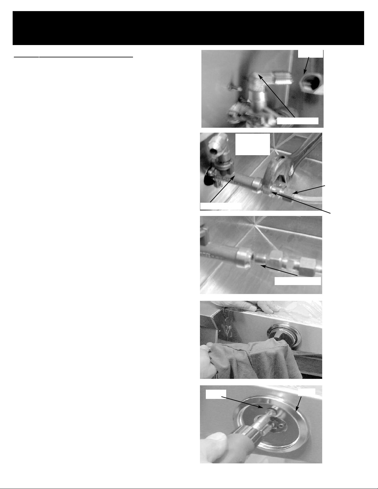
1. Loosen the gas supply hose attached to the side
burner valve using an adjustable wrench. (See
Fig. 29)
2. Once removed, the LP regulator and hose can be
completely removed from the grill. (See Fig. 29)
3. Loosen the aluminum line going from the side
burner valve to the side burner, using and
adjustable wrench. (See Fig. 30)
Note: First remove the aluminum line fitting, then
remove the fitting attached to the valve.
Remove the aluminum line completely from the side
burner valve (See Fig. 31)
4. Remove the control knob from the front of the side
burner. (Use a pair of pliers with a cloth to avoid
any scratches or dents on the knobs) (See Fig. 32)
Valve Assembly
Flex Line
Fig 29
Valve Assembly
Underside of
right side
burner shelf
Fig 30
Loosen
this first.
Loosen this
second.
Note: Metal knobs on the 44” grill can be
removed by hand.
5. Remove the screw holding the bezel in place on
the side burner and remove bezel from front of
side burner. (See Fig. 33)
Scre
Fig 31
Gas Supply Line
Fig 32
w
Bezel
Fig 33
Page 9
Sonoma CGR30
Natural Gas Conversion Instructions
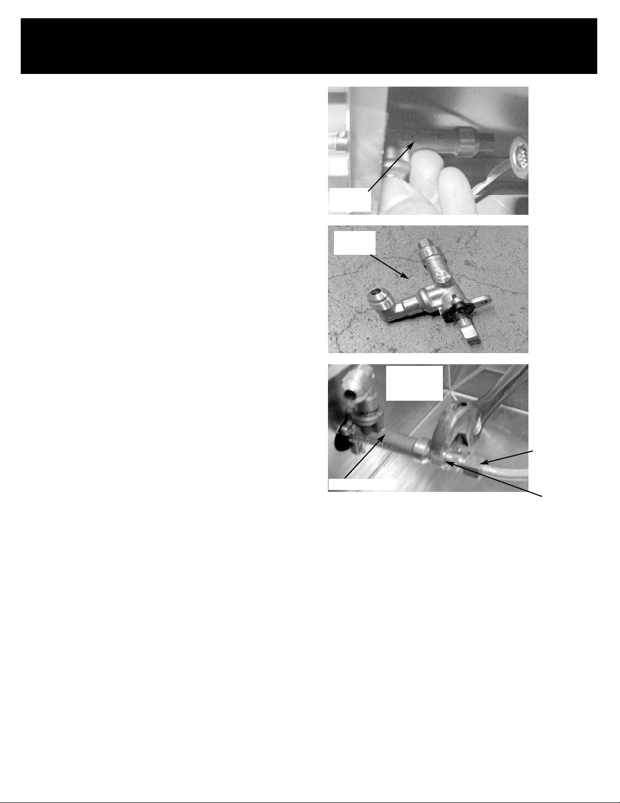
6. Remove LP valve assembly from the side burner.
7. Install new NG valve assembly and bezel into the
side burner assembly. (See Fig. 34-35)
Note: The valve assembly is held in place by the
front bezel screw.
8. Connect the new gas supply hose to the side
burner valve. (See Fig. 29 again)
Note: The hose should be routed through the
same hole from which the LP regulator hose was
removed.
9. Reattach aluminum line from the new LP valve to
the side burner. (See Fig. 36)
Fig 34
LP valve
Assembly
LP valve
Assembly
Fig 35
Note: First attach the fitting attached to the
valve. then the aluminum line fitting
10. Tighten the aluminum line going from the side
burner valve to the side burner, using and
adjustable wrench. (See Fig. 36)
11. Reattach the control knob onto the valve stem,
making sure “OFF” is facing upwards. (See Fig.
32, again)
Valve Assembly
Underside of
right side
burner shelf
Fig 36
Attach
Second
Attach First
Page 10

Sonoma CGR30
Natural Gas Conversion Instructions
12. Remove side burner assembly (copper tubing
assembly)
13. Install new assembly that came with the kit.
14. Reconnect gas inlet tubing and tighten.
15. Using the 9/32” or 7mm nut driver tighten the NG
orifice in the main burner assembly.
16. This completes the side burner conversion.
17. At the completion of the conversion, a leak test
should be performed on all fittings. See Use and
Care manual for leak testing procedure
Proceed to rear infrared burner conversion.
Page 11
Sonoma CGR30
Natural Gas Conversion Instructions
Converting the Rear Infrared Burner to NG
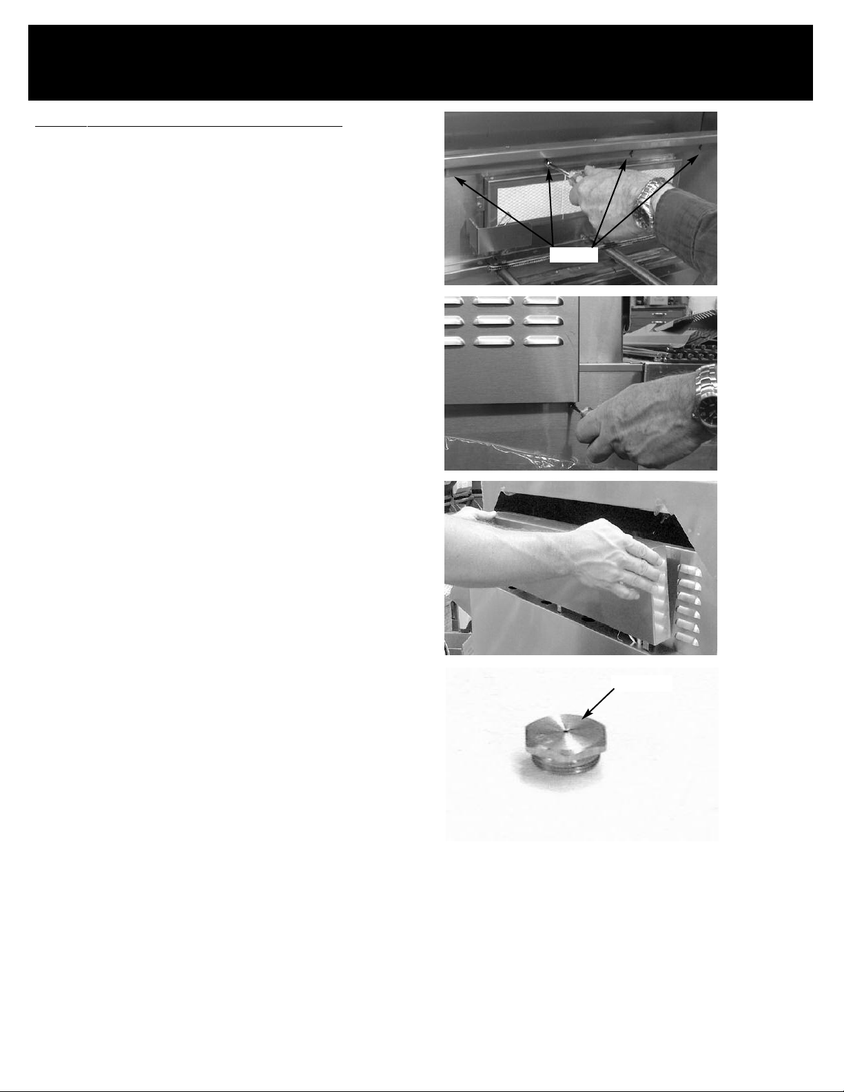
1. Remove the four (4) screws on the inside of the grill
that hold the rear infrared cover in place. (See Fig. 37)
2. Close the grill hood slowly,
Fig 37
3. Remove the two (2) screws from the back infrared
cover, located on the back of the grill. (See Fig. 38)
4. Grasp rear infrared cover and remove it from the grill.
(See Fig. 39)
5. Disconnect flex line and twist orifice elbow to remove
LP orifice.
Completely remove the LP orifice from the flared fitting
6.
and set aside. (See Fig. 40)
7. NG orifice (See Fig. 40)
8. Install the NG orifice into the flared fitting and tighten
completely with an adjustable wrench.
8. Replace the rear infrared co
9. Install the two (2) screws on the back infrared cover,
located on the bac
k of the g
ver (See Fig. 39, again)
rill. (See Fig. 38)
Screws
Fig 38
Fig 39
Open hood.
10.
11. Reinstall the screws that hold the rear infrared cover
in place. (See Fig. 37, again)
ersion complete.
Rear Infr
12.
13. This completes the conversion, a leak test should be
performed on all fittings. See Use and Care manual
for leak testing procedure
ared Bur
ner con
v
NG orifice
Fig 40
RMP-122-30COCI
02/9/05
 Loading...