

Page 1

Temperature and humidity module
AM2301 Product Manual
www.aosong.com
Page 2

Pin
Color
Name
Description
1
Red
VDD
Power (3.3V-5.2V)
2
Yellow
SDA
Serial data,Dual-port
3
Black
GND
Ground
4 NC
Empty
1、Product Overview
AM2301 capacitive humidity sensing digital temperature and humidity module is the one that contains the
compound has been calibrated digital signal output of the temperature and humidity sensor. Application of a
dedicated digital modules collection technology and the temperature and humidity sensing technology, to ensure
that the product has high reliability and excellent long-term stability. The sensor includes a capacitive sensor wet
components and a high-precision temperature measurement devices, and connected with a high-performance
8-bit microcontroller. The product has excellent quality, fast response, strong anti-jamming capability, and
high cost. Each sensor is extremely accurate humidity calibration chamber calibration. The form of procedures,
the calibration coefficients stored in the microcontroller, the sensor within the processing of the heartbeat to call
these calibration coefficients. Standard single-bus interface, system integration quick and easy. Small size, low
power consumption, signal transmission distance up to 20 meters, making it the best choice of all kinds of
applications and even the most demanding applications. Products for the 3-lead (single-bus interface)
connection convenience. Special packages according to user needs.
Physical map Dimensions (unit: mm)
2、Applications
HVAC, dehumidifier, testing and inspection equipment, consumer goods, automotive, automatic control, data
loggers, home appliances, humidity regulator, medical, weather stations, and other humidity measurement and
control and so on.
3、Features
Ultra-low power, the transmission distance, fully automated calibration, the use of capacitive humidity sensor,
completely interchangeable, standard digital single-bus output, excellent long-term stability, high accuracy
temperature measurement devices.
4、The definition of single-bus interface
4.1 AM2301 Pin assignments
Table 1: AM2301 Pin assignments
PIC1: AM2301 Pin Assignment
Aosong(Guangzhou) Electronics Co.,Ltd. TEL:020-36042809 / 36380552 www.aosong.com
- 1 -
Page 3

Parameter
Condition
min
typ
max
Unit
Resolution
0.1 %RH
Range
0
99.9
%RH
Accuracy
[1]
25℃
±3 %RH
Repeatability
±1 %RH
Exchange
Completely interchangeable
Response
[2]
1/e(63%)
<6 S
Sluggish
±0.3 %RH
Drift
[3]
Typical
<0.5
%RH/yr
5.2 Temperature
Table 3: AM2301 Relative temperature performance
Parameter
Condition
min
typ
max
Unit
Resolutio
n
0.1 ℃
16 bit
Accuracy
±0.3
±1 ℃ Range
-40 80 ℃ Repeat
±0.2 ℃
Exchange
Completely interchangeable
Response
1/e(63%)
<10 S
Drift
±0.3
℃/yr
4.2 Power supply pins(VDD GND)
AM2301 supply voltage range 3.3V - 5.2V, recommended supply voltage is 5V.
4.3 Serial data(SDA)
SDA pin is tri structure for reading, writing sensor data. Specific communication timing, see the detailed
description of the communication protocol.
5、Sensor performance
5.1 Relative humidity
Table 2: AM2301 Relative humidity performance table
Pic2: At25℃ The error of relative humidity Pic3:The maximum temperature error
6、Electrical Characteristics
Electrical characteristics, such as energy consumption, high, low, input, output voltage, depending on the
power supply. Table 4 details the electrical characteristics of the AM2301, if not identified, said supply voltage of
5V. To get the best results with the sensor, please design strictly in accordance with the conditions of design in
Table 4.
Aosong(Guangzhou) Electronics Co.,Ltd. TEL:020-36042809 / 36380552 www.aosong.com
- 2 -
Page 4

Parameter
Condition
min
typ
max
Unit
Voltage
3.3 5 5.2
V
Power
consumption
[4]
Dormancy
10
15 µA
Measuring
500 µA
Average
300 µA
Low level output
voltage
I
OL
[5]
0
300
mV
High output
voltage
Rp<25 kΩ
90%
100%
VDD
Low input voltage
Decline
0 30%
VDD
Input High
Voltage
Rise
70%
100%
VDD
Rpu
[6]
VDD = 5V
VIN = VSS
30
45
60
kΩ
Output current
turn on
8
mA
turn off
10
20 µA
Sampling period
2 S
[1] the accuracy of the factory inspection, the sensor
25 ° C and 5V, the accuracy specification of test
conditions, it does not include hysteresis and
nonlinearity, and is only suitable for non-condensing
environment.
[2] to achieve an order of 63% of the time required
under the conditions of 25 ℃ and 1m / s airflow.
[3] in the volatile organic compounds, the values may
be higher. See the manual application to store
information.
[4] this value at VDD = 5.0V when the temperature
is 25 ℃, 2S / time, under the conditions of the
average.
[5] low output current.
[6] that the pull-up resistor.
Table 4: AM2301 DC Characteristics
7、Single-bus communication(ONE-WIRE)
7.1 Typical circuits for single bus
Microprocessor and AM2301 connection typical application circuit is shown in Figure 4. Single bus
communication mode, pull the SDA microprocessor I / O port is connected.
Special instructions of the single-bus communication:
1.Typical application circuit recommended in the short cable length of 30 meters on the 5.1K
pull-up resistor pullup resistor according to the actual situation of lower than 30 m.
2.With 3.3V supply voltage, cable length shall not be greater than 100cm. Otherwise, the line
voltage drop will lead to the sensor power supply, resulting in measurement error.
3.Read the sensor minimum time interval for the 2S; read interval is less than 2S, may cause the
real-time data that need continuous read twice, we recommend repeatedly to read sensors, and each read
sensor interval is greater than 2 seconds to obtain accuratethe data.
temperature and humidity are not allowed or communication is unsuccessful, etc..
4.Temperature and humidity values are each read out the results of the last measurement For
Aosong(Guangzhou) Electronics Co.,Ltd. TEL:020-36042809 / 36380552 www.aosong.com
- 3 -
Page 5
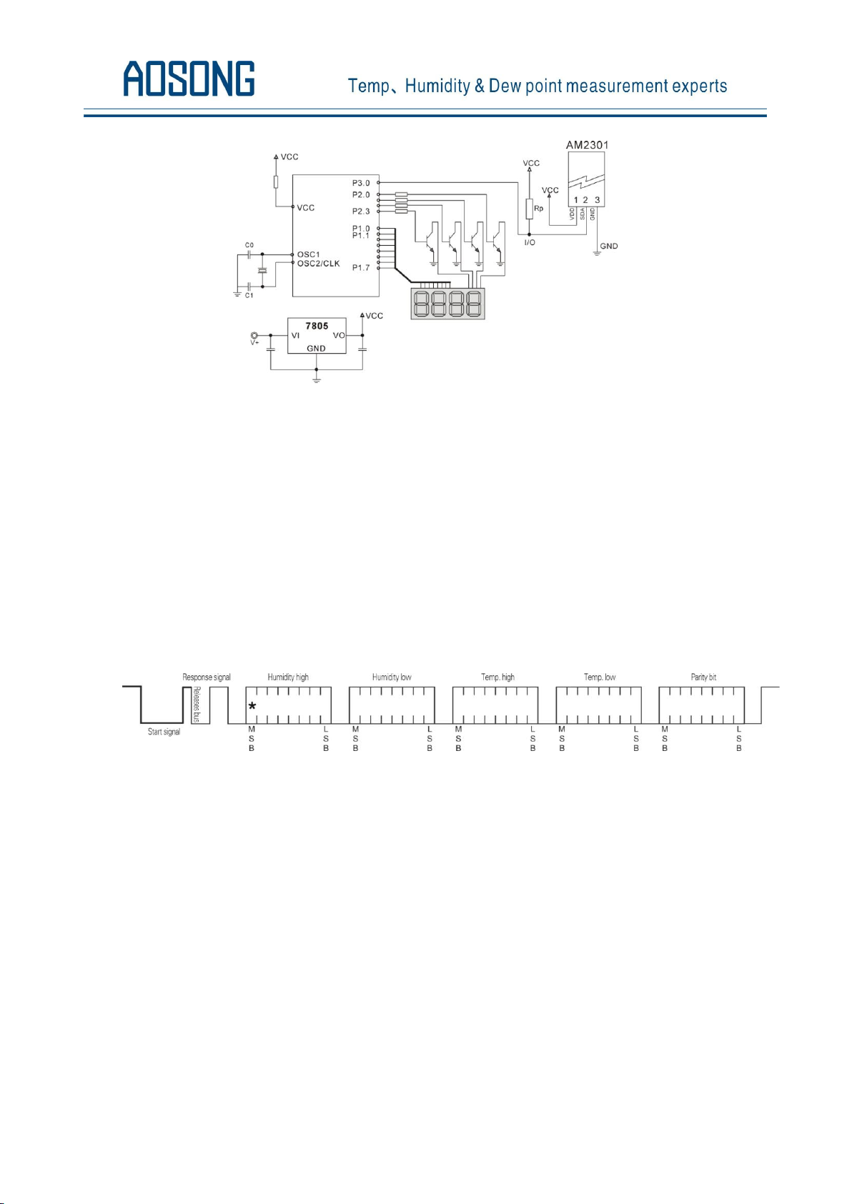
Pic4: AM2301 Typical circuits for single bus
7.2、Single-bus communication protocol
◎Single bus Description
AM2301 device uses a simplified single-bus communication. Single bus that only one data line, data
exchange system, controlled by the data line to complete. Equipment (microprocessor) through an
open-drain or tri-state port connected to the data line to allow the device does not send data to release the
bus, while other devices use the bus; single bus usually require an external about 5.1kΩ pull-up resistor, so
when the bus is idle, its status is high. Because they are the master-slave structure, only the host calls the
sensor, the sensor will answer, so the hosts to access the sensor must strictly follow the sequence of single bus,
if there is a sequence of confusion, the sensor will not respond to the host.
◎Single bus to send data definition
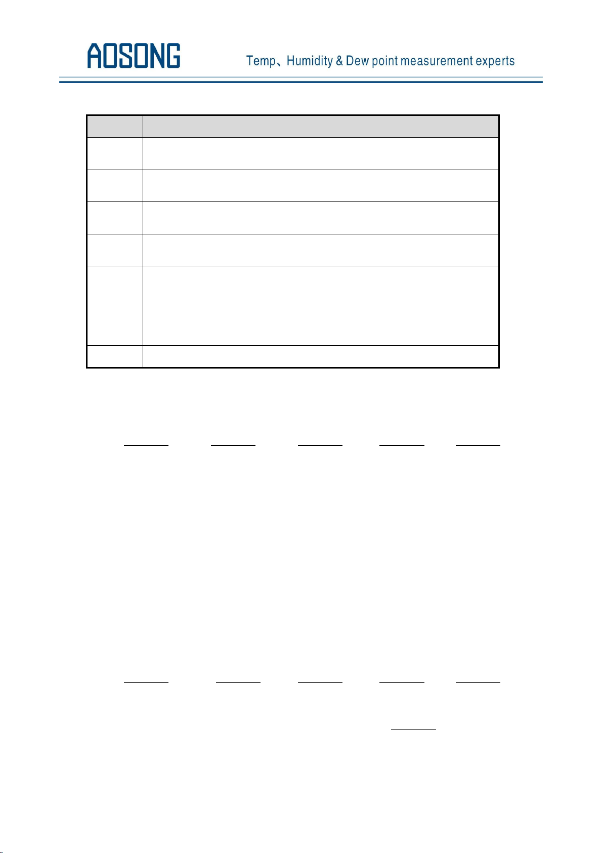
SDA For communication and synchronization between the microprocessor and the AM2301, single-bus
data format, a transmission of 40 data, the high first-out. Specific communication timing shown in Figure 5,
the communication format is depicted in Table 5.
Pic5: AM2301 Single-bus communication protocol
Aosong(Guangzhou) Electronics Co.,Ltd. TEL:020-36042809 / 36380552 www.aosong.com
- 4 -
Page 6
Name
Single-bus format definition
Start signal
Microprocessor data bus (SDA) to bring down a period of time (at least 800μ s) [1] notify the
sensor to prepare the data.
Response
signal
Sensor data bus (SDA) is pulled down to 80μ s, followed by high-80μ s response to host the
start signal.
Data format
Host the start signal is received, the sensor one-time string from the data bus (SDA) 40 data, the
high first-out.
Humidity
Humidity resolution of 16Bit, the previous high; humidity sensor string value is 10 times the
actual humidity values.
Temp.
Temperature resolution of 16Bit, the previous high; temperature sensor string value is 10 times
the actual temperature value;
The temperature is the highest bit (Bit15) is equal to 1 indicates a negative temperature, the
temperature is the highest bit (Bit15) is equal to 0 indicates a positive temperature;
Temperature in addition to the most significant bit (Bit14 ~ bit 0) temperature values.
Parity bit
Parity bit = humidity high + humidity low + temperature high + temperature low
Table 5:AM2301 Communication format specifier
◎Single-bus data calculation example
Example 1:40 Data received:
0000 0010 1001 0010 0000 0001 0000 1101 1010 0010
High humidity 8 Low humidity 8 High temp. 8 Low temp. 8 Parity bit
Calculate:
0000 0010+1001 0010 +0000 0001+0000 1101= 1010 0010(Parity bit)
Received data is correct:
humidity:0000 0010 1001 0010 = 0292H (Hexadecimal)= 2×256 + 9×16 + 2 = 658
=> Humidity = 65.8%RH
Temp.:0000 0001 0000 1101 = 10DH(Hexadecimal) = 1×256 + 0×16 + 13 = 269
=> Temp.= 26.9℃
◎Special Instructions:
When the temperature is below 0 ℃, the highest position of the temperature data.
Example: -10.1 ℃ Expressed as 1 000 0000 0110 0101
Temp.:0000 0000 0110 0101 = 0065H(Hexadecimal)= 6×16 +5 = 101
=> Temp. = -10.1℃
Example 2:40 received data:
0000 0010 1001 0010 0000 0001 0000 1101 1011 0010
High humidity 8 Low humidity 8 High temp. 8 Low temp. 8 Parity bit
Calculate:
0000 0010+1001 0010 +0000 0001+0000 1101= 1010 0010 ≠ 1011 0010 (Validation error)
The received data is not correct, give up, to re-receive data.
Aosong(Guangzhou) Electronics Co.,Ltd. TEL:020-36042809 / 36380552 www.aosong.com
- 5 -
Page 7
Symbol
Parameter
min
typ
max
Unit
Tbe
Host the start signal down time
0.8 1 20
mS
Tgo
Bus master has released time
20
30
200
µS
T
rel
Response to low time
75
80
85
µS
T
reh
In response to high time
75
80
85
µS
T
LOW
Signal "0", "1" low time
48
50
55
µS
TH0
Signal "0" high time
22
26
30
µS
TH1
Signal "1" high time
68
70
75
µS
Ten
Sensor to release the bus time
45
50
55
µS
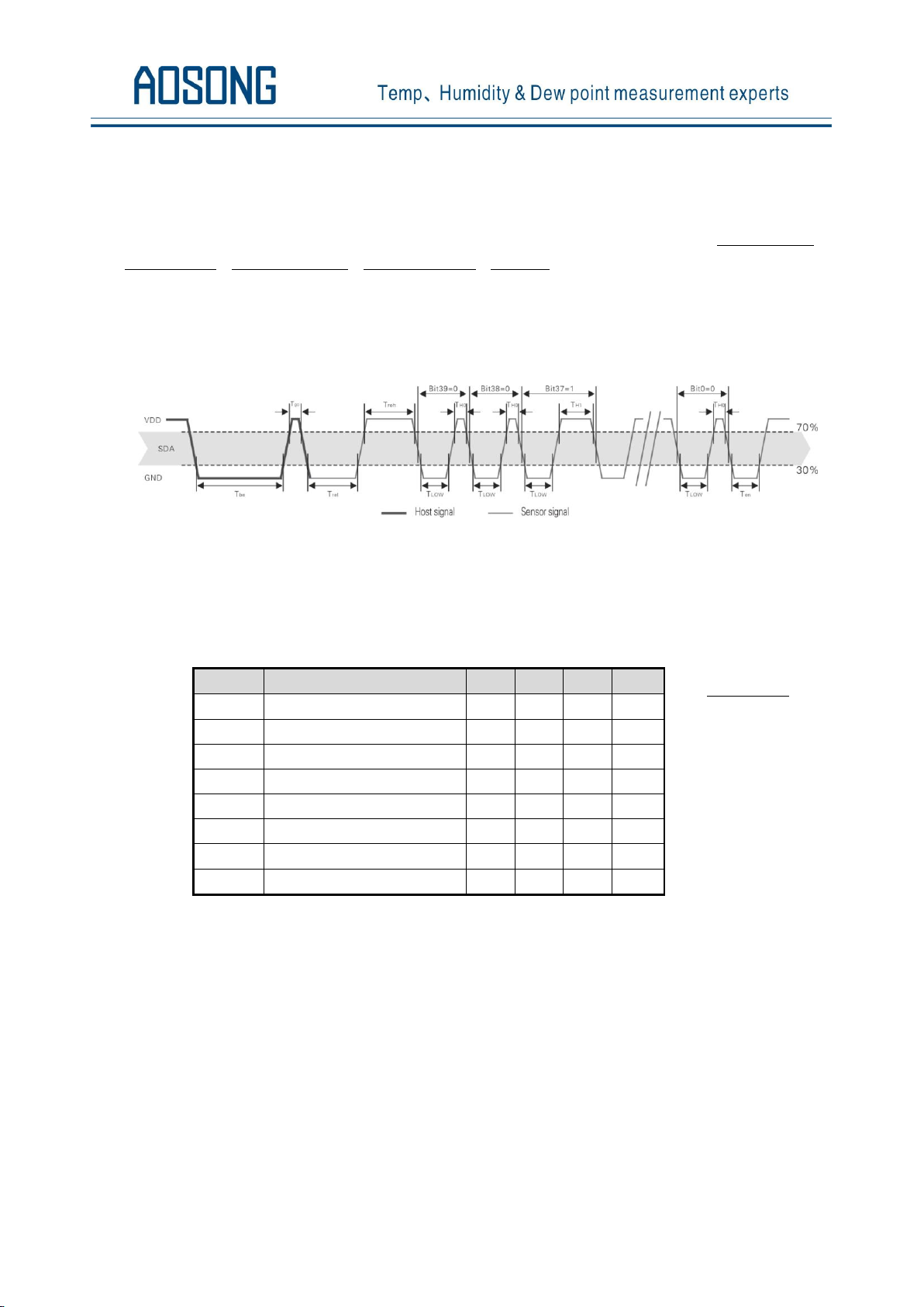
Note:To ensure the
accurate communication
of the sensor, the read
signal, in strict
accordance with the
design parameters and
timing in Table 6 and
Figure 6.
7.3 Single-bus communication timing
User host (MCU) to send a start signal (data bus SDA line low for at least 800μ s) after AM2301 from Sleep
mode conversion to high-speed mode.The host began to signal the end of the AM2301 send a response signal
sent from the data bus SDA serial 40Bit's data, sends the byte high; data sent is followed by: Humidity high、
Humidity low、Temperature high、Temperature low、Parity bit,Send data to the end of trigger information
collection, the collection end of the sensor is automatically transferred to the sleep mode, the advent until the
next communication.
Detailed timing signal characteristics in Table 6,Single-bus communication timing diagram Pic 6:
Pic 6:AM2301 Single-bus communication timing
Note: the temperature and humidity data read by the host from the AM2301 is always the last measured value, such as the
two measurement interval is very long, continuous read twice to the second value of real-time temperature and humidity values,
while two readtake minimum time interval be 2S.
Table 6: Single bus signal characteristics
7.4 Peripherals read step example
Communication between the host and the sensor can read data through the following three steps to
complete.
Step 1
AM2301 have to wait for the power (on AM2301 power 2S crossed the unstable state, the device can not
send any instructions to read during this period), the test environment temperature and humidity data, and
record data, since the sensor into a sleep state automatically. AM2301 The SDA data line from the previous
pull-up resistor pulled up is always high, the AM2301 the SDA pin is in input state, the time detection of
external signal.
Aosong(Guangzhou) Electronics Co.,Ltd. TEL:020-36042809 / 36380552 www.aosong.com
- 6 -
Page 8
Step 2
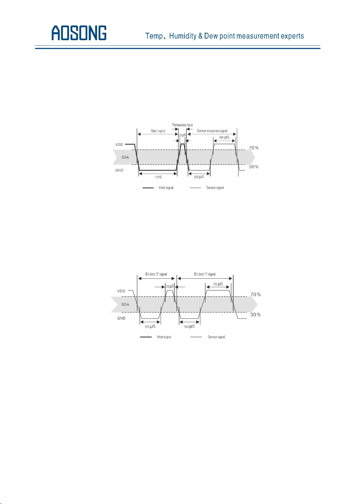
Microprocessor I/O set to output, while output low, and low hold time can not be less than 800us, typical
values are down 1MS, then the microprocessor I/O is set to input state, the release of the bus, due to the
pull-up resistor, the microprocessor I/O AM2301 the SDA data line also will be high, the bus master has
released the AM2301 send a response signal, that is, the output 80 microseconds low as the response signal,
tightthen output high of 80 microseconds notice peripheral is ready to receive data signal transmission as shown
to Pic7 :
Pic7:Single bus decomposition of the timing diagram
Step 3
AM2301 sending the response, followed by the data bus SDA continuous serial output 40 data, the
microprocessor receives 40 data I/O level changes.
Bit data "0" format: 26-28 microseconds 50 microseconds low plus high;
Bit data "1" format: the high level of low plus, 50 microseconds to 70 microseconds;
Bit data "0" bit data "1" format signal shown to pic 8:
Pic 8:The single bus break down the timing diagram
AM2301 data bus SDA output 40 data continue to output the low 50 microseconds into the input state,
followed by pull-up resistor goes high. AM2301 internal re-test environmental temperature and humidity data,
and record the data, the end of the test records, the microcontroller automatically into hibernation.
Microcontroller only after receipt of the start signal of the host wake-up sensor, into the working state.
7.5 Peripheral to read flow chart
AM2301 sensor read single bus flow chart diagram shown in Figure 9, we also provide the C51 read the
code examples, customers need to download, please visit our website (www.aosong.com) related to
downloadthis manual does not provide the code description.
Aosong(Guangzhou) Electronics Co.,Ltd. TEL:020-36042809 / 36380552 www.aosong.com
- 7 -
Page 9
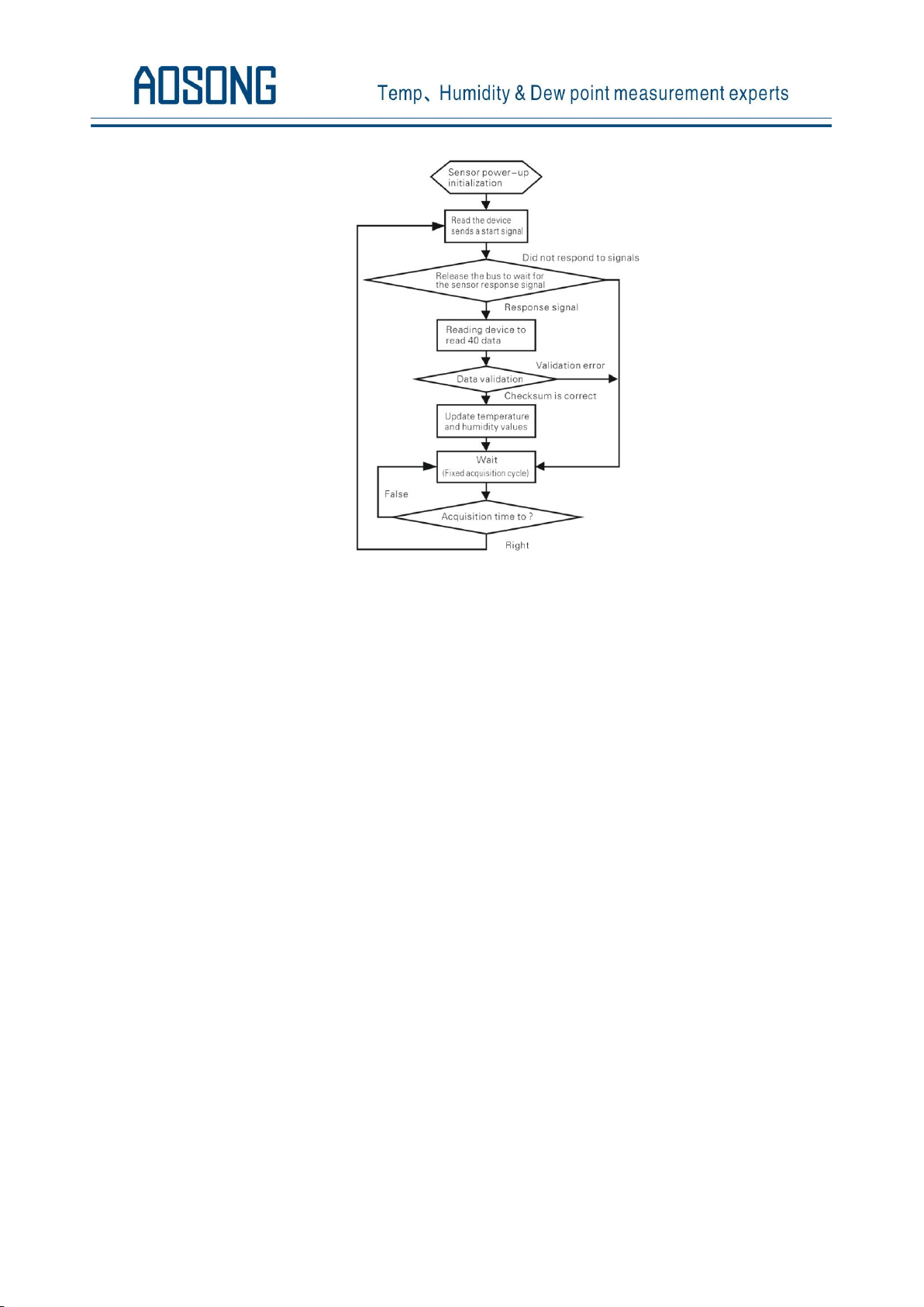
Pic9:Single-bus to read the flow chart
8、Application of information
1. Work and storage conditions
Outside the sensor the proposed scope of work may lead to temporary drift of the signal up to 300%RH. Return to
normal working conditions, sensor calibration status will slowly toward recovery. To speed up the recovery process
may refer to "resume processing". Prolonged use of non-normal operating conditions, will accelerate the aging of the
product.
Avoid placing the components on the long-term condensation and dry environment, as well as the following
environment.
A, salt spray
B, acidic or oxidizing gases such as sulfur dioxide, hydrochloric acid
Recommended storage environment
Temperature: 10 ~ 40℃ Humidity: 60%RH or less
2. The impact of exposure to chemicals
The capacitive humidity sensor has a layer by chemical vapor interference, the proliferation of chemicals in the
sensing layer may lead to drift and decreased sensitivity of the measured values. In a pure environment, contaminants
will slowly be released. Resume processing as described below will accelerate this process. The high concentration of
chemical pollution (such as ethanol) will lead to the complete damage of the sensitive layer of the sensor.
3. The temperature influence
Relative humidity of the gas to a large extent dependent on temperature. Therefore, in the measurement of humidity,
Aosong(Guangzhou) Electronics Co.,Ltd. TEL:020-36042809 / 36380552 www.aosong.com
- 8 -
Page 10

should be to ensure that the work of the humidity sensor at the same temperature. With the release of heat of
electronic components share a printed circuit board, the installation should be as far as possible the sensor away from
the electronic components and mounted below the heat source, while maintaining good ventilation of the enclosure.
To reduce the thermal conductivity sensor and printed circuit board copper plating should be the smallest possible,
and leaving a gap between the two.
4. Light impact
Prolonged exposure to sunlight or strong ultraviolet radiation, and degrade performance.
5. Resume processing
Placed under extreme working conditions or chemical vapor sensor, which allows it to return to the status of
calibration by the following handler. Maintain two hours in the humidity conditions of 45℃ and <10% RH (dry);
followed by 20-30℃ and> 70%RH humidity conditions to maintain more than five hours.
6. Wiring precautions
The quality of the signal wire will affect the quality of the voltage output, it is recommended to use high quality
shielded cable.
7. Welding information
Manual welding, in the maximum temperature of 300℃ under the conditions of contact time shall be less than 3
seconds.
8. Product upgrades
Details, please the consultation Aosong electronics department.
9、The license agreement
Without the prior written permission of the copyright holder, shall not in any form or by any means, electronic
or mechanical (including photocopying), copy any part of this manual, nor shall its contents be communicated to a
third party. The contents are subject to change without notice.
The Company and third parties have ownership of the software, the user may use only signed a contract or
software license.
10、Warnings and personal injury
This product is not applied to the safety or emergency stop devices, as well as the failure of the product may
result in injury to any other application, unless a particular purpose or use authorized. Installation, handling, use or
maintenance of the product refer to product data sheets and application notes. Failure to comply with this
recommendation may result in death and serious personal injury. The Company will bear all damages resulting
personal injury or death, and waive any claims that the resulting subsidiary company managers and employees and
agents, distributors, etc. that may arise, including: a variety of costs, compensation costs, attorneys' fees, and so on.
Aosong(Guangzhou) Electronics Co.,Ltd. TEL:020-36042809 / 36380552 www.aosong.com
- 9 -
Page 11

11、Quality Assurance
The company and its direct purchaser of the product quality guarantee period of three months (from the date of
delivery). Publishes the technical specifications of the product data sheet shall prevail. Within the warranty period, the
product was confirmed that the quality is really defective, the company will provide free repair or replacement. The
user must satisfy the following conditions:
① The product is found defective within 14 days written notice to the Company;
② The product shall be paid by mail back to the company;
③ The product should be within the warranty period.
The Company is only responsible for those used in the occasion of the technical condition of the product
defective product. Without any guarantee, warranty or written statement of its products used in special applications.
Company for its products applied to the reliability of the product or circuit does not make any commitment.
Aosong(Guangzhou) Electronics Co.,Ltd. TEL:020-36042809 / 36380552 www.aosong.com
- 10 -
 Loading...