

Page 1

QUICK START GUIDE
Version 1.2 13th November 2009
Introduction
The Sonnox Restore suite is a collection of three plug-ins designed to clean the sound of digital
audio recordings that are damaged:
• by pops, clicks, or crackle;
• by hum, buzzes and whines;
• or by noise.
The tools are not just for restoring old material, but also for removing the clicks, pops, buzzes
and background noises that can sometimes accidentally occur in new recordings.
A great deal of time has been put into making the Sonnox Restore suite as intuitive as possible in
terms of providing excellent visual and graphical feedback. They also include some innovative
solutions not seen before in the restoration field, the intention being to enable quick and accurate
repair of a variety of spoiled recordings.
This quick-start guide contains a description of the most important controls and some initial
guidelines to help the first-time user set up and use the plug-ins for the first time.
The user manual documents the plug-ins in full and should be consulted to get the best out of the
plug-ins.
Restoration Processing Workflow
It is usual practice to use the DeClick process first, particularly if there are large disturbances
present that require repair.
The optimal order for DeNoise and DeBuzz is probably dependent on the programme material. If
a loud buzz is dominating low-level noise it would be sensible to remove the buzz first; on the
other hand the presence of significant noise might make it more difficult for the DeBuzz detector
to lock on to a low level buzz component.
1
Page 2
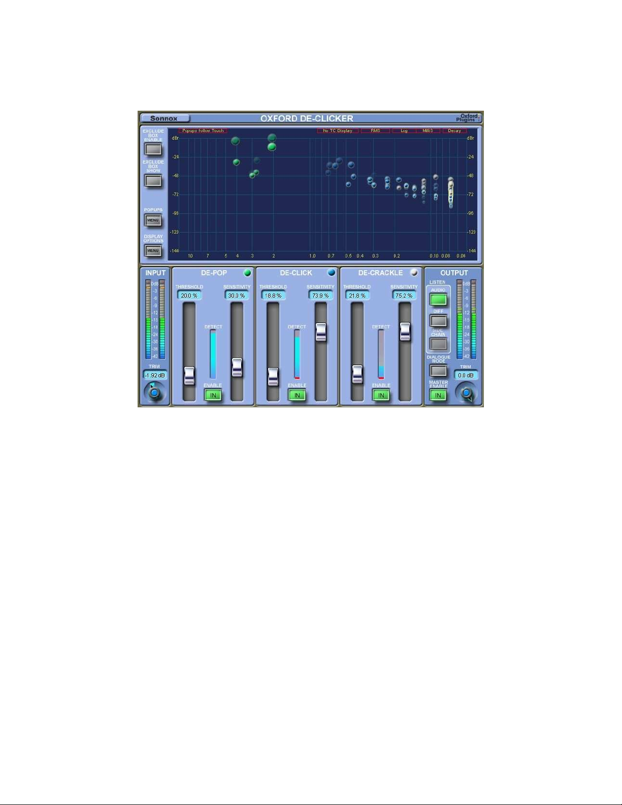
The Oxford DeClicker
Description of Controls - DePop, DeClick and DeCrackle Sections
“Threshold” – This control is used to adjust a threshold level within the excitation profile to
capture an event. If a peak on the excitation profile is below the threshold, it will not be
registered as an event to be repaired. If a peak breaches the threshold line, then it is registered as
a detected event and can be repaired.
“Sensitivity” – This control determines whether detected events are discarded, starting with the
smallest. A low sensitivity means only the largest of the detected events go forwards to the repair
section.
“Enable” –With the section disabled, the detectors are still monitoring the audio and any
detected events are shown on the Events Graph as red bubbles. Setting the section IN will
present the detected events to the repair processing.
2
Page 3

Quick Start Guide for the Oxford DeClicker
1. Lower the DePop Threshold until it is sitting just above the floor of the Excitation Profile.
2. Lower the Sensitivity until only the Pops you want to remove are being removed, and nothing
more.
3. Repeat 1 and 2 for DeClick section.
4. Repeat 1 and 2 for DeCrackle section.
5. Review the material all the way through to check if the settings are good for all the material. If
not, consider snap shot automation of different passages, or for dialogue consider using the
Dialogue Mode.
6. Remember that a useful tip is to automate the Exclude Box Enable button.
Quick Start Guide for Dialogue Mode
1. Click on Dialogue Mode button.
2. Adjust the Voice Threshold slider to make the threshold be just above the background level
while the speaker pauses.
3. Click on the “Below Set” button, and adjust the Threshold/Sensitivity controls of all three
sections to make repairs to the background.
4. Click on the “Above Set” button, and adjust the Threshold/Sensitivity controls of all three
sections to make repairs to the speech.
5. Listen to the material to evaluate the repair work all the way through. If not, consider using the
side-chain to make the Above/Below decision be based on a particular band of the frequency
spectrum rather than the overall level.
To Set up the Side Chain
To set up the Side Chain, first click on the Side Chain button in the listen section of the output
panel, so you hear the output of the Side Chain. Then adjust the LF filter and HF filter to isolate
the band you want to use to feed the Voice Threshold control. What you are hearing is what is
fed to the Voice Threshold, which determines whether the input signal is Above or Below the
threshold. Then go back to listening to the audio output.
You will notice that when you touch the LF or HF controls, the graph shows you an FFT plot of
the signal. You can drag the end stops in (which are the LF and HF controls), and drag the
threshold level (which is the Voice Threshold) to set it all up according to what you are seeing.
3
Page 4
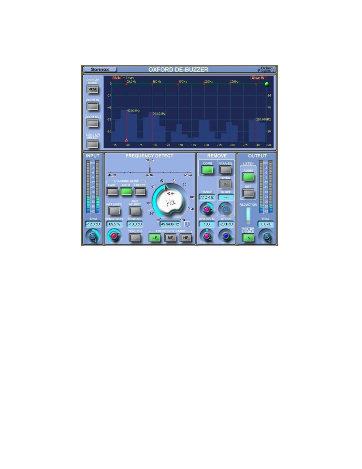
The Oxford DeBuzzer
Description of Controls – Frequency Detect Section
“Auto” – Auto mode is the default tracking mode. In this mode the removal filters automatically
follow the peak frequency found in the peak profile. It is suitable for tracking a weak, slowly
wandering fundamental and operates over all three frequency bands.
“Fast” – Fast tracking mode allows the removal filters to automatically follow a quickly
wandering fundamental. This mode operates on MF and HF frequency selections only.
“Freeze” – For a fundamental that is a fixed frequency, once the auto mode has found the best
nominal frequency, you can freeze the nominal. In freeze mode, the removal filters follow the
value of the nominal frequency set by the big rotary frequency control.
“Sensitivity” – Start at a high value and back off to the point at which the hum becomes audible
again, then push it up a little to make the hum disappear. Doing this correctly ensures least
damage to the signal.
4
Page 5

“Alt Mode” – This allows two different modes for hum removal. Try both modes with the
sensitivity knob, and use the mode that allows the lowest setting of the sensitivity.
“Tone On” – Enables the onboard tone generator which can be useful for finding the frequency
of unusual hums, whines or whistles.
“Tone dB” – Allows you to set the level of the tone generator.
“Fine Adjust” – Sets the Frequency control to have a much finer range so that it is easy to
home into a precise frequency value. Holding down shift while moving the Frequency knob
enables an extreme fine adjust, where the frequency can be accurately determined to 0.0001 Hz.
If Fine Adjust is selected while in Auto tracking mode, the detector is forced into Freeze mode
and the Freeze mode button flashes. Exiting Fine Adjust returns to Auto mode.
“LF”, “MF”, “HF” – These three buttons set which frequency band the big rotary control will
operate over. LF = 20Hz to 160Hz. MF = 160Hz to 1280Hz. HF = 1280Hz to 20kHz. The peak
profile is not active for the HF range.
“Hz”. The Frequency control in the centre is used to set the nominal frequency about which in
Auto mode the detection algorithms hunt for a peak in the peak profile. In Freeze mode it
determines the frequency of the removal filters. The frequency can be selected using the scribble
tab in units of 1Hz (normal), 0.01Hz (Fine adjust) and 0.0001Hz (extreme fine adjust).
Description of Controls – Remove Section
“Comb” – Sets the removal filters to be a comb filter. Comb is best for auto mode, and for when
there are many harmonics in a buzz.
“Para-EQ” – Sets the removal filters to be a narrow notching parametric EQ. You may prefer
the sound of these filters when there are few harmonics.
“+Even” – When using the Para-EQ option, by default even harmonics are not notched out
because frequently they are not present. Enabling this control will notch out even harmonics as
well.
“Range” – This sets the frequency range above which there are no notches. This needs to be as
low as possible to avoid loss of MF and HF information, but high enough to take out all the
harmonics of a buzz.
“Atten” – Set this to the minimum attenuation that will make the hum or buzz inaudible.
5
Page 6

“Sharp/Q” – Adjusts the width or sharpness of the notches. When too sharp, the filters tend to
ring. When too wide, the filters take out too much of the audio around the harmonics. So
adjusting this is a matter of finding a suitable compromise.
Quick Start Guide for the Oxford DeBuzzer
1. Find the nominal frequency. Start with the Sensitivity at maximum, Range and Atten controls
at medium settings, and Sharp/Q relatively wide. Alt Mode off.
If it is a low frequency buzz you are looking to remove, then play the music through the plug-in
for a while and look at the FFT plot. It will give you an idea of any persistent low frequencies.
Then set the big central rotary control to that frequency, or click on the peak in the FFT plot to
do the same thing. If that is the right frequency, you will hear the hum disappear. If not, look at
the peak profile to see what is happening. If there is no discernable peak then you may be an
octave too high, so try going to half that frequency.
If it is a higher frequency, set to Freeze mode, just look for it in the FFT plot, and click on the
peak that is found.
2. Once the hum has disappeared, you then need to refine the removal process to make it remove
only the minimum necessary. To do this, click on Diff so you can hear what is being removed.
3. Next, adjust the Range (either using the control, or by dragging the green drag handle on the
graph) to bring it down to being just above the highest harmonic you want to remove.
4. Next, adjust the Sharp/Q control to be the best compromise between being too wide (too
much audio is heard with the hum) or too narrow (the filters ring too much).
5. Next, switch back to listening to Audio mode, and reduce the Atten control clockwise so that
the hum is just inaudible.
6. Next, adjust the Sensitivity control to be as low as possible (to cause least damage); simply
reduce the sensitivity from 100 until the hum or buzz becomes just audible, then increase slightly
until it disappears. Repeat this with Alt Mode on. Use the Mode which allows the Sensitivity to
be least.
7. Decide if you want to try using the parametric EQ to remove the hum. If so, you may need to
re-adjust the Sharp/Q, and set the Slope.
6
Page 7
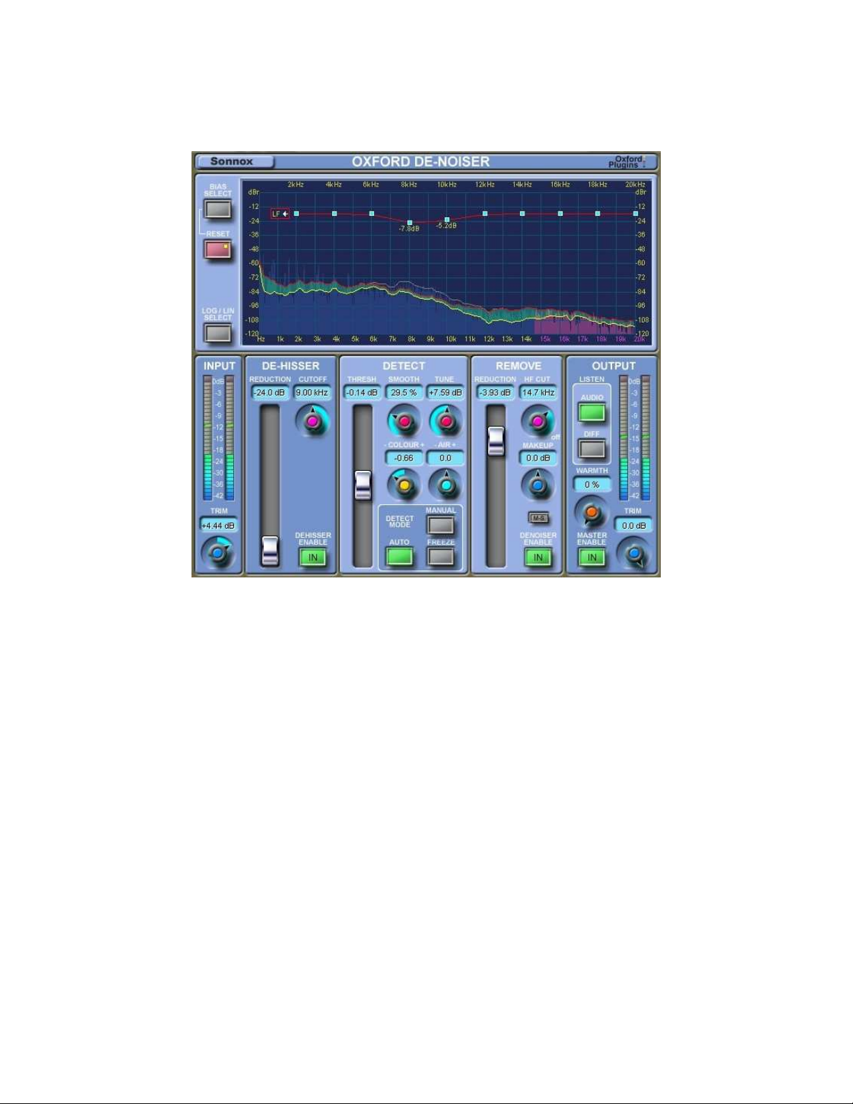
The Oxford DeNoiser
Description of Controls – DeHisser Section
“Cutoff” – This controls how far down the spectrum hiss removal is done. Can be set in the
range 3kHz to 15kHz.
“Reduction” – This sets how many dBs of hiss reduction will be applied, up to -24dB.
“Enable” – If Master Enable is also IN, this makes the DeHisser active using glitchless
switching.
Description of Controls – DeNoiser Detect Section
“Thresh” – This is the most critical control to get right. It sets the level of the threshold about
which noise reduction takes place. Frequency components below the threshold get attenuated,
whereas components above the threshold are left alone. If Thresh is set too high, signal will be
attenuated; if set too low, not enough noise will be removed.
7
Page 8

“Smooth” - Adjusts the peakiness of the noise profile.
“Tune” – In some situations can help to remove musical noise.
“Auto” Mode - Enables automatic updating of noise profile and the noise profile level relative
to the input signal.
“Freeze” Mode – Once you have obtained a good profile, this button will freeze the profile to
prevent it updating.
“Manual” Mode – In this mode, the profile is forced flat to represent white noise. You can then
use the “Colour”, “Air” and bias controls to modify the shape of the profile.
“Colour” – Modifies the LF shape of the noise profile.
“Air” – Modifies the HF shape of the noise profile.
Description of Controls – DeNoiser Removal Section
“Reduction” – sets the amount of attenuation of broadband noise components below the
threshold.
“HF Cut” – This is a simple low-pass filter with a fixed -18dB attenuation. It is active when the
DeNoiser Enable and Master Enable are both active.
“Makeup” – Provides a way to adjust the level of the de-noised signal to compensate for any
loss in level due to the de-noising process. This makes it easier to perform with and without denoising comparisons using the master IN button.
“Enable” – If Master Enable is also IN, this makes the broadband DeNoiser active using
glitchless switching.
Description of Controls – Display
“Bias Select” – This toggles between the red bias curve that modifies the shape of the noise
threshold profile, and the yellow bias curve that modifies the shape of the noise reduction.
8
Page 9

“Reset Biases” – When a bias handle is moved this button lights half-bright to indicate that the
bias curve is non-null. A single press nulls the bias control handles for the currently active and
visible bias curve; using shift-click will reset the bias handles for both the LF and HF sections of
the currently active bias curve. A small red or yellow dot indicates that the non-selected bias
curve is non-null.
“Log / Lin Select” – Switches the display between logarithmic (LF) and linear (HF) modes.
Quick Start Guide for the DeHisser Section
1. Click on the IN button of the DeHisser.
2. Set Cutoff to the desired frequency between 3kHz and 15kHz..
3. Set the Reduction to 0dB. Lower slowly to the point where hiss reduction is acceptable.
Quick Start Guide for the Oxford DeNoiser (Simple Broad-band Noise Removal)
1. Leave in Auto mode. For simple broad-band noise reduction, set the Reduction slider of the
Remove section to around -12dB.
2. Adjust the Thresh slider to find the right balance between being too low (not enough noise is
removed) and too high (too much audio is also removed). You may find it easier to listen to Diff
mode, where you are listening to what has been removed. The idea is to have the maximum
amount of noise and hiss in this signal, with the minimum amount of original signal.
3. See if adjusting the Smooth control gives a more pleasing result.
4. If necessary, adjust the Tune control to reduce “twinklies” (musical noise).
5. Set the Reduction to 0dB, and then very slowly lower the control until the amount of noise
reduction is acceptable.
6. You can use the Makeup control in the removal section to do some critical comparison.. After
noise reduction, the level of the signal may be significantly lower. If this is so, you can use the
Makeup control to add gain to make it closer to the original. Then you can use the master IN
button to do glitch-less comparison of with and without noise-reduction, comparing like-level
with like-level.
9
Page 10

7. Once you are happy that you have a sympathetic treatment of the noise, you can then consider
adding some warmth back to the output using the Warmth control.
Quick Start Guide for the Oxford DeNoiser (Complex Noise Removal)
The DeNoiser provides significant ability to vary the shape of the noise threshold profile and the
noise removal. For best results, here are some additional suggestions.
1. For surgical noise removal, set the Reduction slider of the Remove section to 0dB and
activate the yellow reduction bias curve using Bias Select button. This allows the noise
reduction to be modified in smaller frequency bands. Listen to the audio signal, and bring down
the grab handles on the yellow curve. Listen to the removal of noise in that band, and carefully
balance against the preservation of the audio signal.
2. Now listen to the critical frequencies of the material to evaluate whether you could adjust the
red threshold bias curve to be more sympathetic to these parts. This would mean slightly
lowering the threshold bias handles in the critical regions of the frequency spectrum to reduce
noise reduction there and preserve more of the original audio, and perhaps to lift the bias controls
in the HF area to remove more hiss.
3. If you have a constant noise floor, try to find a segment with no signal and use Freeze mode.
All the threshold profile and noise reduction biasing controls will help you modify the curves.
4. Surprisingly good results can be obtained quickly using a manually-shaped fixed curve. Select
Manual mode. Use the Colour control to modify the noise profile at LF, perhaps by mimicking
a pink noise curve. Use the Air control to modify the noise profile at HF, which can help
preserve HF signal frequencies. The noise profile can be further shaped in smaller frequency
bands by using the bias curve handles.
10
 Loading...