


SNP-LU8500 / SNP-LU8500+ /
SNP-LW8500 / SNP-LW8500+
USER MANUAL

The CD included with this printed manual contains an electronic copy in English. Please read all instructions before
using or servicing this product.
Die mit dieser gedruckten Anleitung gelieferte CD enthält eine elektronische Kopie in Deutsch. Bitte lesen Sie alle
Anweisungen, bevor Sie dieses Produkt verwenden oder warten.
Le DC fourni avec ce manuel imprimé contient une copie électronique en français. S'il vous plaît lire toutes les
instructions avant d'utiliser ou de réparer ce produit.
Il CD fornito con il manuale stampato contiene una copia elettronica in lingua italiano. Si prega di leggere tutte le
istruzioni prima di utilizzare o riparare questo prodotto.
El DC incluido con este manual impreso contiene una copia electrónica en español. Por favor, lea todas las
instrucciones antes de usar o dar servicio a este producto.
NOTICES
REGULATORY
The product has been tested and found to comply with the limits for a Class A digital device,
pursuant to Part 15 of the FCC Rules. These limits are designed to provide reasonable protection
against harmful interference when the product is operated in a commercial environment. The
product generates, uses, and can radiate radio frequency energy and, if not installed and used in
accordance with the instruction manual, may cause harmful interference to radio communications.
Operation of the product in a residential area is likely to cause harmful interference in which case
the user will be required to correct the interference at the user's own expense.
WARNING! Changes or modifications not expressly approved by the manufacturer could void the
user's authority to operate the product.
FOR COMMERCIAL USE ONLY - POUR USAGE COMMERCIAL UNIQUEMENT
THIS DEVICE COMPLIES WITH PART 15 OF THE FCC RULES. OPERATION IS SUBJECT TO
THE FOLLOWING 2 CONDITIONS: (1) THIS DEVICE MAY NOT CAUSE HARMFUL
INTERFERENCE (2) THIS DEVICE MUST ACCEPT ANY INTERFERENCE RECEIVED,
INCLUDING ANY INTERFERENCE THAT MAY CAUSE UNDESIRED OPERATION.
THIS CLASS A DIGITAL APPARATUS MEETS ALL REQUIREMENTS OF THE CANADIAN
INTERFERENCE-CAUSING EQUIPMENT REGULATIONS.
CET APPAREIL NUMÉRIQUE DE CLASSE A EST CONFORME AUX NORMES DÉFINIES DANS
LES RÉGLEMENTATIONS CANADIENNES SUR LES APPAREILS CAUSANT DES
INTERFÉRENCES RADIO (CANADIAN INTERFERENCE-CAUSING EQUIPMENT
REGULATIONS, ICES-003, CLASS A).

Table of Contents
Projector User Manual
i
1. SAFETY
2. INTRODUCTION
2.1 Projector Components .................................................................................................. 2-1
2.2 Built-in Keypad..............................................................................................................2-4
2.3 Input/Output (I/O) Panel................................................................................................ 2-5
2.4 LED Status Indicators................................................................................................... 2-6
2.5 Remote Control............................................................................................................. 2-7
2.5.1 Projector Addressing........................................................................................ 2-9
2.5.2 Remote Control Keycode Table..................................................................... 2-10
3. SPECIFICATIONS
3.1 Inputs ............................................................................................................................ 3-1
3.2 PIP/PBP Compatibility .................................................................................................. 3-4
3.3 Key Features ................................................................................................................ 3-4
3.4 List of Components....................................................................................................... 3-4
3.5 Optional Accessories .................................................................................................... 3-5
3.6 Environment Condition ................................................................................................. 3-5
3.7 Regulatory .................................................................................................................... 3-6
3.8 Federal Communications Commission (FCC) Warning................................................ 3-7
3.9 OSD Tree...................................................................................................................... 3-8
4. INSTALLATION
4.1 Connect to Computer.................................................................................................... 4-1
4.2 Connect to Video Equipment ........................................................................................ 4-2
4.3 Turn the Projector On ................................................................................................... 4-3
4.4 Turn the Projector Off ................................................................................................... 4-4
4.5 Adjust the Projector Position......................................................................................... 4-4
4.6 Lens Offset ................................................................................................................... 4-5
4.7 Removing and Installing the Lens................................................................................. 4-7
5. OPERATION
5.1 Picture Menu.................................................................................................................5-2
5.2 Output Menu ................................................................................................................. 5-5
5.3 Setup Menu .................................................................................................................. 5-9
5.4 Option Menu ............................................................................................................... 5-11

Section 1: SAFETY
Projector User Manual
1-1
1. SAFETY
Read through this document in its entirety and understand all warnings and
precautions before attempting to operate the projector.
Important Information
Laser Safety Cautions:
• This product is classified as CLASS 1 LASER PRODUCT - RISK GROUP 2
of IEC 60825-1 : 2014, Complies with FDA Document issued on February
18, 2015 : Classification and Requirements for Laser Illuminated Projectors
(LIPs), complies with 21 CFR 1040.10 and 1040.11 as a Risk Group 2 , LIP
( Laser Illuminated Projector) as defined in IEC 62471:2006 except for
deviations pursuant to Laser Notice No. 50, dated June 24, 2007
• This projector has built-in Class 4 laser module. Disassembly or
modification is very dangerous and should never be attempted.
• Any operation or adjustment not specifically instructed by the user’s guide
creates the risk of hazardous laser radiation exposure.
• Do not open or disassemble the projector as this may cause damage by the
exposure of laser radiation.
• Do not stare into beam when the projector is on. The bright light may result
in permanent eye damage.
• When turning on the projector, make sure no one within projection range is
looking at the lens.
,(&&/$66/$6(5352'8&75,6.*5283
,(&352'8,7/$6(5'(&/$66(*5283(
'(5,648(
&RQIRUPHDX[QRUPHV&)5HWFRPPH*URXSHGHULVTXH
SURMHFWHXUODVHU/,
3/DVHU,OOXPLQDWHG3URMHFWRUGpILQLSDU&(,
VDXIOHVH[FHSWLRQVFLWpHVGDQVOHGRFXPHQW
/DVHU1RWLFH1GDWpGX-XLQ
$9(57,66(0(17
5D\RQQHPHQWRSWLTXHGDQJHUHX[SRWHQWLHOpPLVS
DUFHSURGXLW1HSDVUHJDUGHU
GLUHFWHPHQWGDQVOHIDLVFHDX&HFLSRXUUDLWrWUHQRFLISRXUOHV\HX[
,
(&䱢㾧ℰẎ⒨5*⍘晐䬰于
晋ṭ㠠㍕㾧ℰ⅓䬓⏞㗌㜆⹛㛯㗌Ḳⷕ⻩⣽䬍⏯&)5⑳⏳
,(&㈧⮁
ḰḲ/,3㾧ℰ䅎㗵㉼⽘㜡ƌ5*⍘晐䬰于
㳏ヶ
㭋Ẏ⒨⏖僤ἁẎ䔆⍘晐㾧ℰ彷⯫˛寞⋦䛛妭㒴ὃℰ㝆ƏỌℴ⯠䜣䝂㍆⮚˛
&RPSOLHVZLWK&)5DQGDV
D5LVN*URXS/,3
/DVHU,OOXPLQDWHG3URMHFWRUDVGHILQHGLQ,(&H[FHSWIRUGHYLDWLRQV
S
XUVXDQWWR/DVHU1RWLFH1RGDWHG-XQH
&$87,21
3RVVLEO\KD]DUGRXVRSWLFDOUDGLDWLRQHPLWWH
GIURPWKLVSURGXFW'RQRWVWDUHDW
RSHUDWLQJEHDP0D\EHKDUPIXOWRWKHH\HV
Section 1: SAFETY
Projector User Manual
1-2
• Without following the control, adjustment or operation procedure may
cause damage by the exposure of laser radiation.
• Adequate instructions for assembly, operation, and maintenance, including
clear warnings concerning precautions to avoid possible exposure to laser.
Installing the Projector Properly
• Please set the projector on nearly-level.
• Be sure to install the projector properly. Improper installation may reduce
the laser diode lifetime andeven cause a fire hazard.
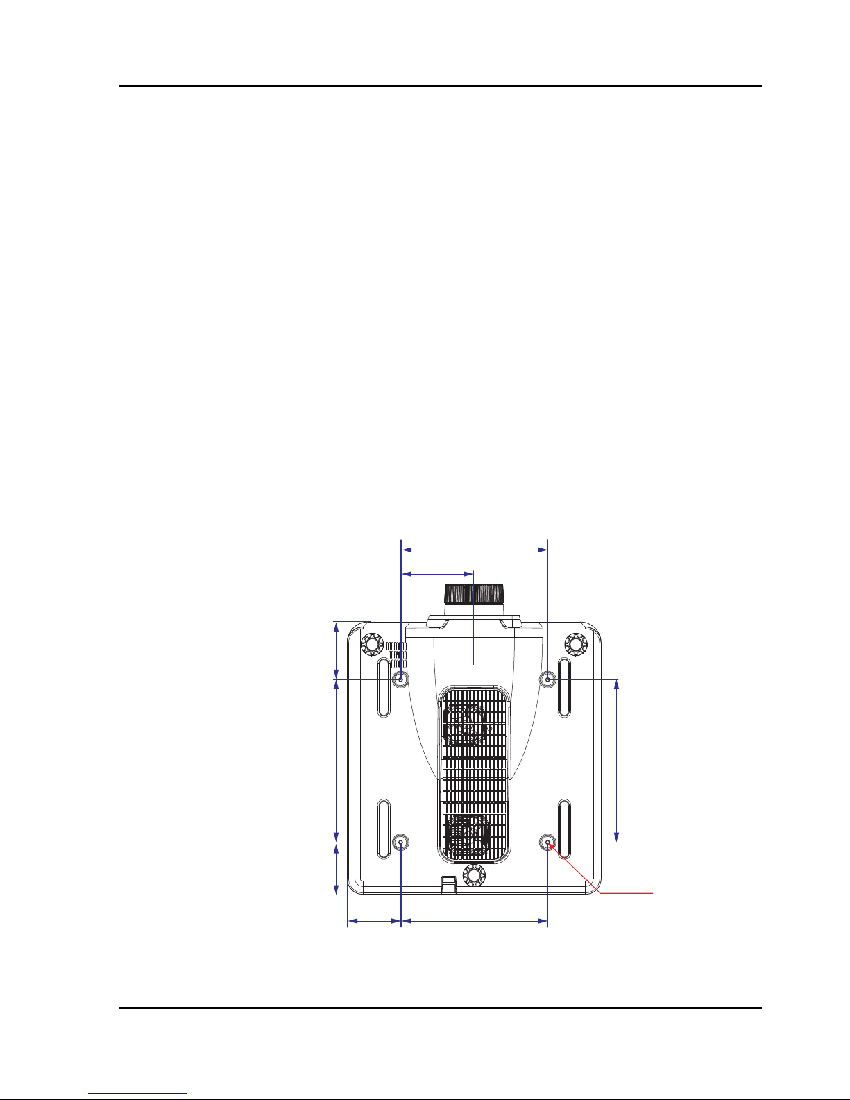
• Caution in ceiling installation the projector:
- Only qualified personal is authorized for ceiling installation.
- We are not responsible for the hurt and damage caused by ceiling
bracket that purchased from unauthorized dealer even in warranty
period.
- Remove the ceiling bracket immediately while not use.
- While installing, torque screwdriver is suggested, don’t use electric or
impact-type screwdriver.
- Please read the manual of bracket for details.
- The bracket is subject to change without notice.
140mm
280mm
280mm102mm
310mm
4-M6x10
310mm 110mm99mm
Section 2: INTRODUCTION
Projector User Manual
2-1
2. INTRODUCTION
The product specified in this document is a high brightness, high-resolution
video/graphics 1-chip laser based projector. The projector is available in
WXGA and WUXGA resolutions. The projector utilizes Digital Light Processing
(DLP
®
) technology from Texas Instruments. It is primarily designed for fixed
installation markets.
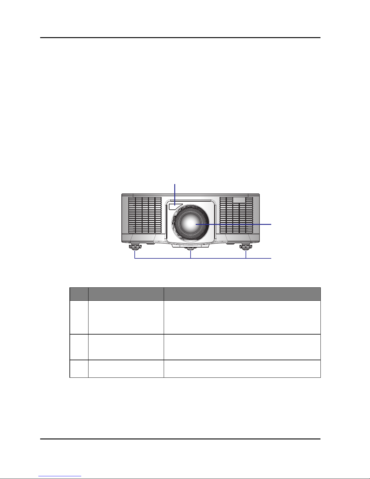
2.1 Projector Components
Front View
Ind. Part Name Description
1 Front IR Receiver
Receives signals from the IR remote. Keep the signal
path to the sensor unobstructed for uninterrupted
communication with the projector.
2 Projection Lens
Allows automated lens control and adjustment:
vertical and horizontal offsets, zoom and focus.
3 Adjustable Feet Raise or lower the feet to level the projector.
1
2
3

Section 2: INTRODUCTION
Projector Series User Manual
2-2
Rear View
Ind. Part Name Description
1 LED Status Indicators Displays the status of the projector.
2 Top IR Sensor
Receives signals from the IR remote. Keep the signal
path unobstructed for uninterrupted communication
with the projector.
3 Connector panel Connects the projector to external devices.
4 Power Switch
Switch the power button to turn on/off the power
source.
5 Power Connector Connect to the supplied power adapter.
6 Kensington Lock Use to secure the projector to countertops, tables, etc.
7 Security bar Use to secure the projector.
8 Keypad Panel Controls the projector.
MENU INPUT
EXIT
LENS
FOCUS
ZOOM
ENTER
12
3
45678

Section 2: INTRODUCTION
Projector User Manual
2-3
Left View
Right View
Ind. Part Name Description
1 Inlet Vent
Keep these vents unobstructed to prevent the
projector from overheating.
2 Outlet Vent
Keep these vents unobstructed to prevent the
projector from overheating.
1
2

Section 2: INTRODUCTION
Projector Series User Manual
2-4
2.2 Built-in Keypad
Ind. Part Name Description
1 Power Turn the projector on or off.
2 Menu Display menus.
3 Exit Return to previous level or exit menus if at top level.
4 Input Select an input for the main or PIP/PBP image.
5 Enter Confirm a selection.
6 Arrow Keys • Adjust a setting UP or DOWN.
• Navigate within a menu.
7 Zoom Adjust zoom.
8 Focus Adjust focus.
9 Lens Adjust the lens vertical or horizontal offset setting.
MENU INPUT
EXIT
LENS
FOCUS
ZOOM
ENTER
1 234
765
8
9

Section 2: INTRODUCTION
Projector User Manual
2-5
2.3 Input/Output (I/O) Panel
RS232 Pin Assignments
Ind. Connector Name Ind. Connector Name
1 DVI-D 7 USB Type A (WIFI dongle)
2 VGA IN 8 REMOTE IN
3 VGA OUT 9 RS-232C
4 HDMI OUT 10 LAN (Ethernet)
5 HDMI IN 11 HDBaseT
6 Mini USB (LAN FW Upgrade) 12 3D SYNC OUT
12345
9
7
68
101112
Pin no.
Spec.
(from projector side)
1N/A
2RXD
3TXD
4N/A
5GND
6N/A
7N/A
8N/A
9N/A
12345
6789

Section 2: INTRODUCTION
Projector Series User Manual
2-6
2.4 LED Status Indicators
The LED status indicators are located on the rear of the projector. Each LED is
defined below.
Message
Light LED Status LED AV Mute LED
Green Orange Red Green Orange Red Green Orange
Standby State
Flashing
Power on
(Warm up)
Flashing
Power on &
Laser diode on
Steady
Steady Steady
Power off
(Cooling down)
Flashing
AV mute is off
(Image is
displayed)
Steady
Steady Steady
AV mute is on
(Image is black)
Steady
Steady Steady
Projector
communication
Steady
Flashing
Steady
Firmware upgrade
Flashing Flashing
Error
(Over temperature)
Steady
Error (Fan failure)
Flashing

Section 2: INTRODUCTION
Projector User Manual
2-7
2.5 Remote Control
ON OFF
21 3
54 6
87 9
Gamma Bright Cont. PIP
0
Info
Mode
Auto
Input
Menu Exit
Hot Key
Shutter
(AV Mute)
Pattern
Focus
Lens H
Lens V
Keystone H
Keystone V
Zoom
Enter
16
17
18
20
21
22
23
24
1
19
2
3
4
5
6
7
8
9
10
11
12
13
14
15

Section 2: INTRODUCTION
Projector Series User Manual
2-8
Ind. Part Name Description
1 Power on Turn projector ON.
2 Number Keys
Enter a number, such as a value for an IP address,
etc.
3 Info Display source image information.
4 Auto Automatically optimize image.
5 Enter
• Select a highlighted menu item.
• Change or accept a value.
6Arrow Keys
• Adjust a setting UP or DOWN.
• Navigate within a menu.
7 Menu Display menus.
8 Bright Adjust amount of light in the image.
9 Gamma Adjust mid-range levels.
10 Lens H Adjust the position of the image horizontally.
11 Lens V Adjust the position of the image vertically.
12 Keystone H Adjust the horizontal keystone.
13 Keystone V Adjust the vertical keystone.
14 Shutter (AV Mute) Display or blank the video image.
15 Hot Key Select your preset keys quickly.
16 OFF Turn projector OFF.
17 Mode Select the preset display mode.
18 Input Select an input for the main or PIP/PBP image.
19 Exit Return to previous level or exit menus if at top level.
20 Cont. Adjust difference between dark and light.
21 PIP Turn PIP/PBP ON/OFF.
22 Focus Adjust focus to improve image clarity as desired.
23 Zoom Adjust zoom to achieve a desired image size.
24 Pattern Display a test pattern.

Section 2: INTRODUCTION
Projector User Manual
2-9
2.5.1 Projector Addressing
The customer code has 100 groups.
a. the preset 1st group:
FACTORY_ID + REMOTE_CODE = 0xA0EB
b. the 2
nd
group until 100th group:
FACTORY_ID1 + REMOTE_CODE1 = 0xB010
FACTORY_ID1 + REMOTE_CODE2 = 0xB011
….
FACTORY_ID1 + REMOTE_CODE99 = 0xB072
The method to change the customer code and code table for ID Code 1 to 99 is
shown below:
Note:
The original code: Press "Hot key" for 3 sec, then release, enter 0 then enter 0
within 2 seconds.
ID Code Change mode
Customer
code
1
Press "Hot key" for 3 sec., release, enter “0” then enter “1”
within 2 sec.
B010
2
Press "Hot key" for 3 sec., release, enter “0” then enter “2”
within 2 sec.
B011
3
Press "Hot key" for 3 sec., release, enter “0” then enter “3”
within 2 sec.
B012
…… …
10
Press "Hot key" for 3 sec., release, enter “1” then enter “0”
within 2 sec.
B019
11
Press "Hot key" for 3 sec., release, enter “1” then enter “1”
within 2 sec.
B01A
…… …
98
Press "Hot key" for 3 sec., release, enter “9” then enter “8”
within 2 sec.
B071
99
Press "Hot key" for 3 sec., release, enter “9” then enter “9”
within 2 sec.
B072

Section 2: INTRODUCTION
Projector Series User Manual
2-10
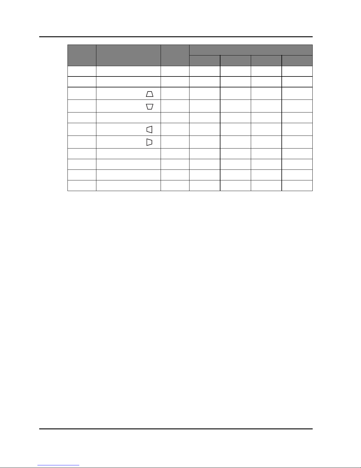
2.5.2 Remote Control Keycode Table
The keycode table for ID Code 0 is shown below:
Key
Position
Key Legend
Repeat
Format
Normal Function
Byte1 Byte2 Byte3 Byte4
1ONF1A0EB12ED
2 OFF F1 A0 EB 02 FD
3 1 F1 A0 EB 31 CE
4 2 F1 A0 EB 32 CD
5 3 F1 A0 EB 33 CC
6 4 F1 A0 EB 34 CB
7 5 F1 A0 EB 35 CA
8 6 F1 A0 EB 36 C9
9 7 F1 A0 EB 37 C8
10 8 F1 A0 EB 38 C7
11 9 F1 A0 EB 39 C6
12 INFO F1 A0 EB 4C B3
13 0 F1 A0 EB 30 CF
14 Mode F1 A0 EB 23 DC
15 Auto Sync F1 A0 EB 15 EA
16 Input F1 A0 EB 14 EB
17 UP F1 A0 EB 40 BF
18 LEFT F1 A0 EB 42 BD
19 Enter F1 A0 EB 13 EC
20 RIGHT F1 A0 EB 43 BC
21 DOWN F1 A0 EB 41 BE
22 Menu F1 A0 EB 1B E4
23 Exit F1 A0 EB 1D E2
24 Gamma F1 A0 EB 0A F5
25 Bright F1 A0 EB 0B F4
26 Contr F1 A0 EB 0C F3
27 PIP F1 A0 EB 0D F2
28 LENS H F1 A0 EB 0E F1
29 LENS H F1 A0 EB 0F F0
30 FOCUS F1 A0 EB 16 E9
31 LENS V F1 A0 EB 1E E1
Section 2: INTRODUCTION
Projector User Manual
2-11
32 LENS V F1 A0 EB 1F F0
33 FOCUS F1 A0 EB 17 E8
34
KEYSTONE H ( )
F1 A0 EB 2C D3
35
KEYSTONE H ( )
F1 A0 EB 2D D2
36 ZOOM F1 A0 EB 18 E7
37
KEYSTONE V ( )
F1 A0 EB 2E D1
38
KEYSTONE V ( )
F1 A0 EB 2F D0
39 ZOOM F1 A0 EB 19 E6
40 Shutter(AV Mute) F1 A0 EB 11 EE
41 Hot key F1 A0 EB 1A E5
42 Pattern F1 A0 EB 1C E3
Key
Position
Key Legend
Repeat
Format
Normal Function
Byte1 Byte2 Byte3 Byte4
Section 3: SPECIFICATIONS
Projector User Manual
3-1
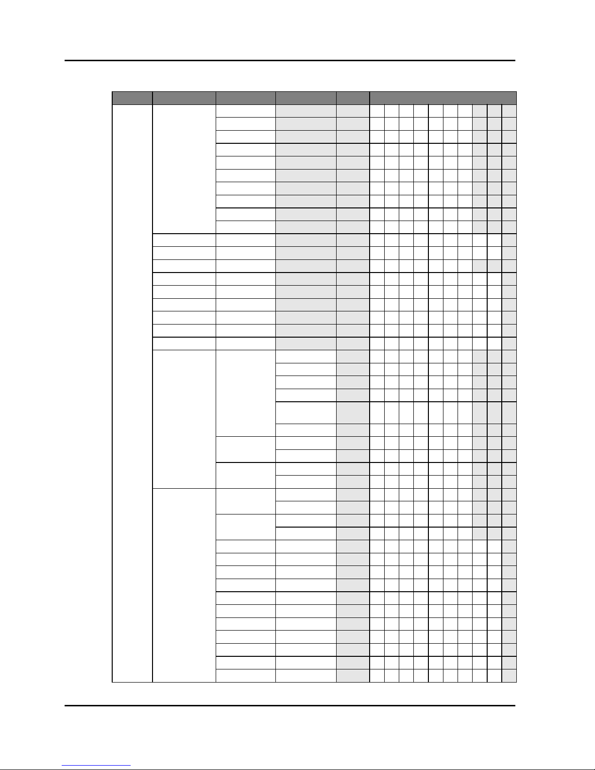
3. SPECIFICATIONS
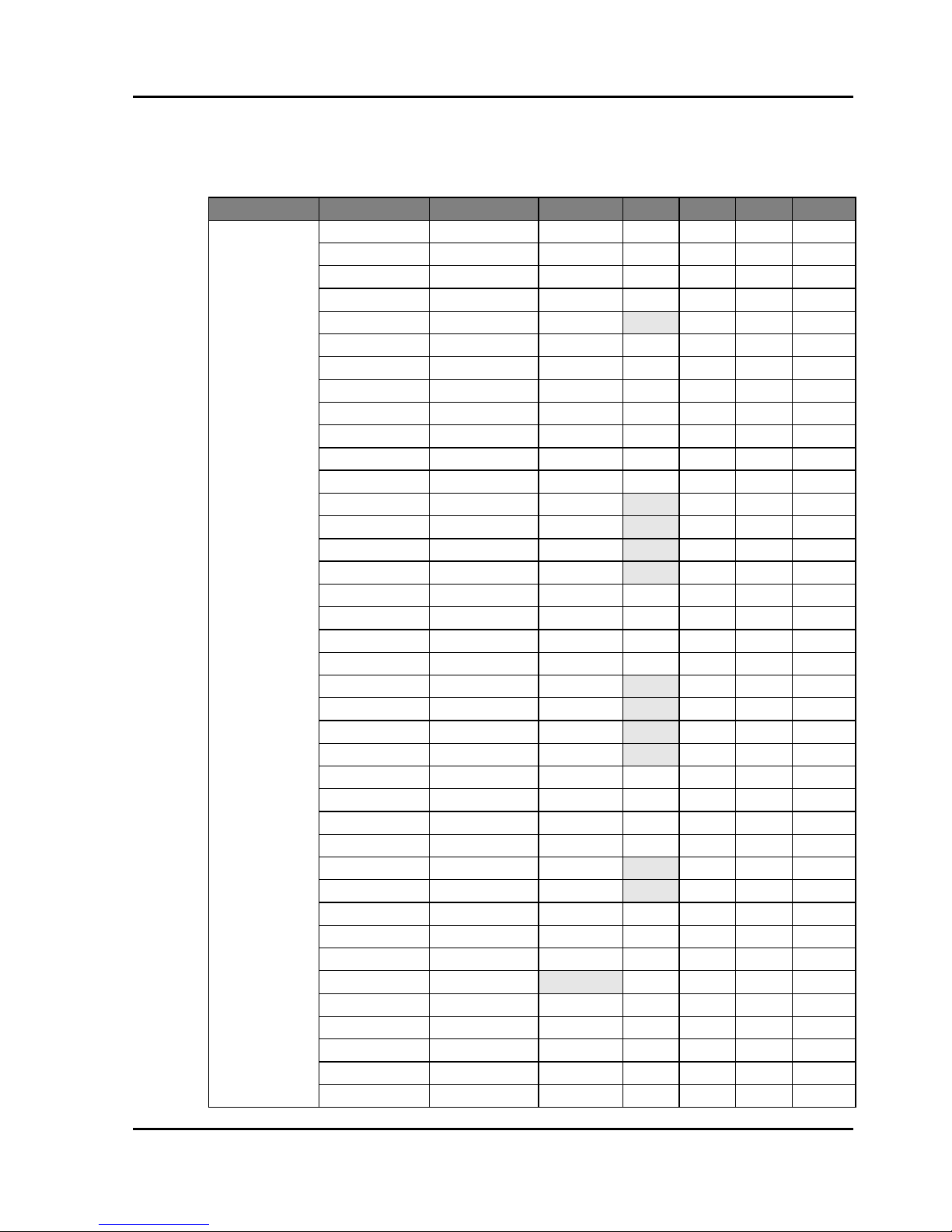
3.1 Inputs
Signal Type Resolution Frame rate (Hz) QD881 VGA HDMI DVI HDBaseT
PC
640x480 60 DMT0660 VVV V
640x480 72 DMT0672 VVV V
640x480 75 DMT0675 VVV V
640x480 85 DMT0685 VVV V
640x480 66.6 APP0667 VV V
720x400 70 IBM0770H VVV V
800x600 60 DMT0860 VVV V
800x600 72 DMT0872 VVV V
800x600 75 DMT0875 VVV V
800x600 85 DMT0885 VVV V
800x600 120 CVR0812 VVV V
832x624 75 8362A75 VVV V
848x480 50 CVT0850H VV V
848x480 60 CVT0860H VV V
848x480 75 CVT0875H VV V
848x480 85 CVT0885H VV V
1024x768 60 DMT1060 VVV V
1024x768 75 DMT1075 VVV V
1024x768 85 DMT1085 VVV V
1024x768 120 CVR1012 VVV V
1152x720 50 CVT1150D VV V
1152x720 60 CVT1160D VV V
1152x720 75 CVT1175D VV V
1152x720 85 CVT1185D VV V
1152x864 60 CVT1160 VVV V
1152x864 70 DMT1170 VVV V
1152x864 75 DMT1175 VVV V
1152x864 85 DMT1185 VVV V
1152x870 75 APP1175 VV V
1280x720 50 CVT1250H VV V
1280x720 60 CVT1260H VVV V
1280x720 75 CVT1275H VVV V
1280x720 85 CVT1285H VVV V
1280x720 120 VVV V
1280x768 60 CVT1260E VVV V
1280x768 75 CVT1275E VVV V
1280x768 85 CVT1285E VVV V
1280x800 50 CVT1250_ VVV V
1280x800 60 DMT1260D VVV V

Section 3: SPECIFICATIONS
Projector User Manual
3-2
PC
1280x800 75 CVT1275_ VVV V
1280x800 85 CVT1285_ VVV V
1280x960 50 CVT1250 VV V
1280x960 60 CVT1260 VVV V
1280x960 75 CVT1275 VVV V
1280x960 85 CVT1285 VVV V
1280x1024 50 CVT1250G VV V
1280x1024 60 DMT1260G VVV V
1280x1024 75 DMT1275G VVV V
1280x1024 85 DMT1285G VVV V
1360x768 50 CVT1350H VV V
1360x768 60 DMT1360H VV V
1360x768 75 CVT1375H VV V
1360x768 85 CVT1385H VV V
1366x768 60 DMR1360H VVV V
1400x1050 50 CVT1450 VV V
1400x1050 60 CVT1460 VV V
1400x1050 75 CVT1475 VVV V
1440x900 60 CVT1460D VVV V
1440x900 75 CVT1475D VV V
1600x900 60 DMR1660H VV V
1600x1200 60 DMT1660 VVV V
1680x1050 60 CVT1660D VVV V
1920X1080 50 CVT1950H VV V
1920X1080 60 CVR1960H VVV V
1920X1200RB 60 CVR1960D VVV V
1920X1200RB 50 CVT1950D VVV V
NTSC NTSC (M, 4.43) 60
PAL
PAL (B,G,H,I) 50
PAL (N) 50
PAL (M) 60
SECAM SECAM (M) 50
SDTV
480i 60 VVV V
576i 50 VVV V
EDTV
480p 60 VVV V
576p 50 VVV V
HDTV
1080i 25 VVV V
1080i 29 VVV V
1080i 30 VVV V
720p 50 VVV V
720p 59 VVV V
720p 60 VVV V
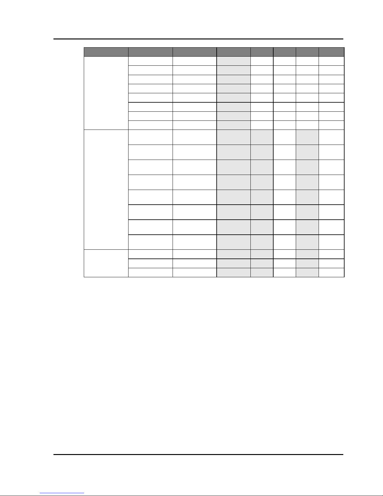
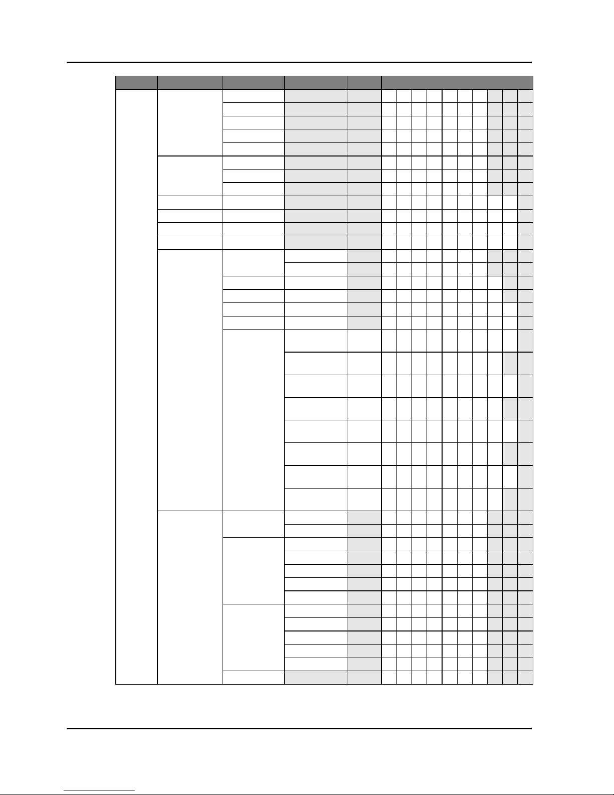
Signal Type Resolution Frame rate (Hz) QD881 VGA HDMI DVI HDBaseT
Section 3: SPECIFICATIONS
Projector User Manual
3-3
NOTE:
"RB" means "reduced blanking".
HDTV
1080p 23 VVV V
1080p 24 VVV V
1080p 25 VVV V
1080p 29 VVV V
1080p 30 VVV V
1080p 50 VVV V
1080p 59 VVV V
1080p 60 VVV V
Mandatory 3D
Frame Packing
1080p
24 V V
Frame Packing
720p
50 V V
Frame Packing
720p
60 V V
Side by Side
1080i
50 V V
Side by Side
1080i
60 V V
Top and Bottom
720p
50 V V
Top and Bottom
720p
60 V V
Top and Bottom
1080p
24 V V
Frame sequential
3D
800x600 120 V V
1024x768 120 V V
1280x720 120 V V
Signal Type Resolution Frame rate (Hz) QD881 VGA HDMI DVI HDBaseT
Section 3: SPECIFICATIONS
Projector User Manual
3-4
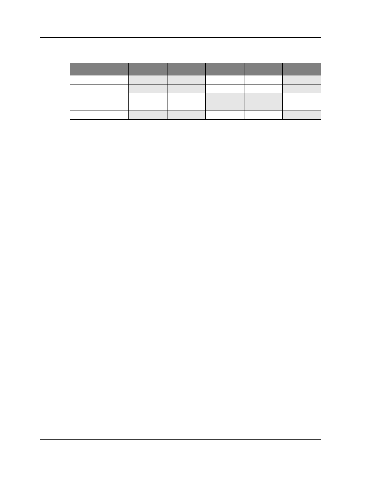
3.2 PIP/PBP Compatibility
V : PIP/PBP combinations are enabled
- : PIP/PBP combinations are disabled
3.3 Key Features
• WXGA: One panel 0.65”-WXGA projection system, w/ TI DDP4421 solution
• WUXGA: One panel 0.67”-WUXGA projection system, w/ TI DDP4422
solution
• Power Zoom/Focus and full lens shift
• Support LAN network control for video streaming
• Support WIFI (optional dongle)
• Support PIP/PBP function
• Support 360 degrees free orientation operation
3.4 List of Components
This projector comes with all the items shown below. Check to make sure your
package is complete. Contact your dealer if anything is missing.
• Remote control x 1
• AAA battery x 2
• AC Power cable x 1 (By region request)
• Lens Cover x 2
- Small size: Compatible with A01, A03, or A13 lens
- Large size: Compatible with A06 lens
• VGA cable x 1
• User manual CD x 1
• Safety Instruction Booklet x 1
• Quick Start Guide x 1
• Warranty card x 1 (By region request)
• Inspection card x 1 (China SKU)
• RoHS Card x 1 (China SKU)
NOTE:
Due to the difference in applications for each country, some regions may have different accessories.
PIP/PBP Matrix HDMI HDBaseT VGA DVI-D LAN
HDMI - - VV -
HDBaseT - - VV -
VGA VV - - V
DVI-D VV - - V
LAN - - VV -
Section 3: SPECIFICATIONS
Projector User Manual
3-5
3.5 Optional Accessories
• Standard Lens (A06)
• Optional Lens (A01)
• Optional Lens (A03)
• Optional Lens (A13)
• Optional Lens (A15)
• Wireless dongle (optional accessory)
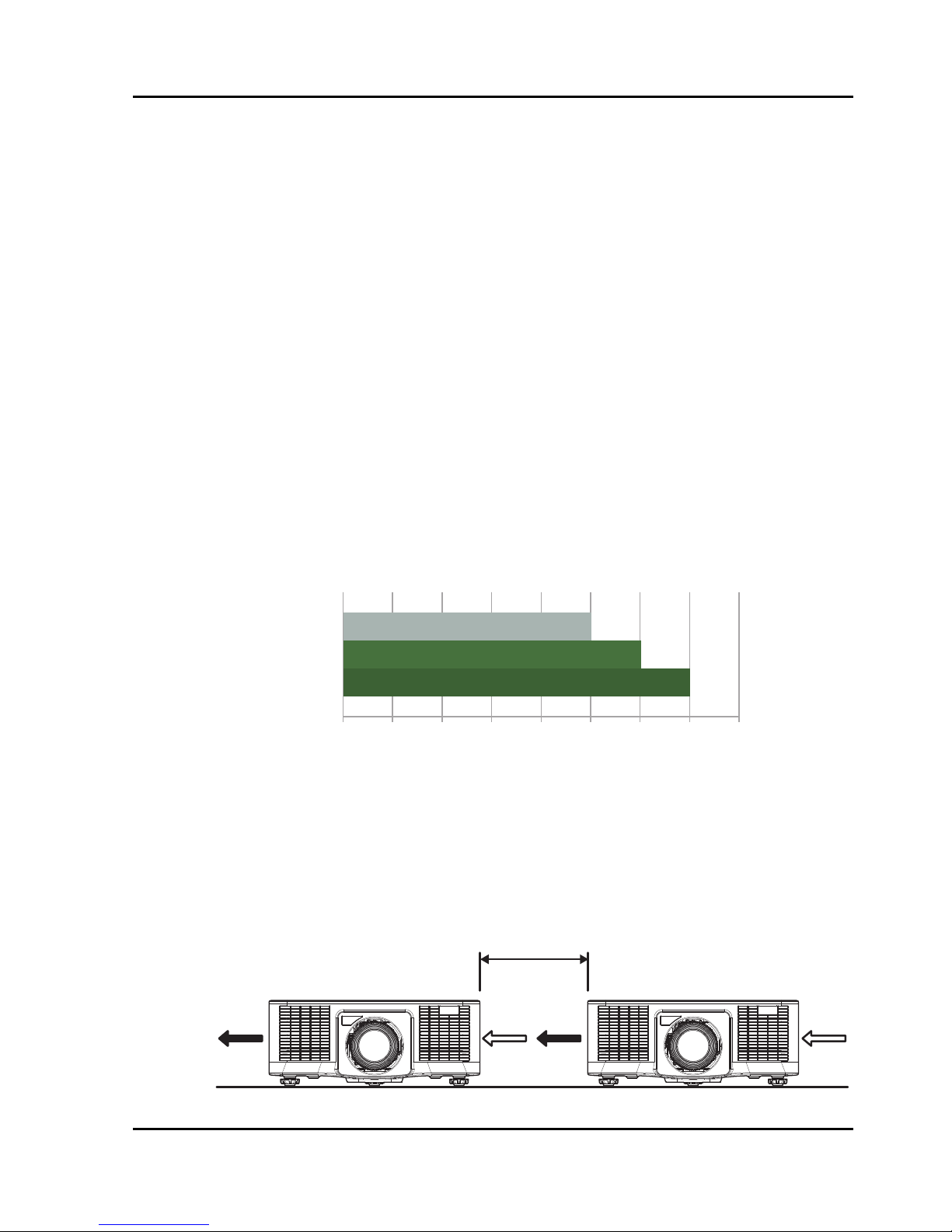
3.6 Environment Condition
• Temperature
- Operating: 5 ~ 40°C
- Storage: -10°C ~ 60°C
• Altitude
- Operating:
- for 0 ~ 2500 ft, 5 ~ 40°C
- for 2500 ~ 5000 ft, 5 ~ 35°C
- for 5000 ~ 10000 ft, 5 ~ 30°C
NOTE:
High altitude >5000 ft
• Humidity
- Operating: 10~85%RH, non-condensing
- Storage: 5~90%RH, non-condensing
• Clearance of Two Operation Projectors
- Clearance > 1m (at least to keep 1m)
10,000
ft
5,000
2,500
0
545°C40353025201510
IntakeIntake OuttakeOuttake
Clearance

Section 3: SPECIFICATIONS
Projector User Manual
3-6
• Clearance for Ceiling Mount Installation
- Need to keep at least 30mm between ceiling mount and bottom intake.
3.7 Regulatory
• Safety
- CSA C22.2 No. 60950-1
- UL 60950-1
- IEC 60950-1
- EN 60950-1
• Electro-Magnetic Compatibility
Emissions
- FCC CFR47, Part 15, Subpart B/ANSI C63.4, Class A - Unintentional
- Radiators -CISPR 22/EN55022 Class A - Information Technology
Equipment
- ICES/NMB003 (A) - Information Technology Equipment
Immunity
- CISPR 24/EN55024 EMC Requirements - Information Technology
Equipment
• Environmental
- The product conforms to:
EU Directive (2011/65/EU) on the restriction of the use of certain
hazardous substances (RoHS) in electrical and electronic
equipment and the applicable official amendment(s).
EU Regulation (EC) No. 1907/2006 on the registration, evaluation,
authorization and restriction of chemicals (REACH) and the
applicable official amendment(s).
EU Directive (2012/19/EU) on waste and electrical and electronic
equipment (WEEE) and the applicable official amendment(s).
China Ministry of Information Industry Order No.39 (02/2006) on the
control of pollution caused by electronic information products, the
10.10
30.00
Bottom Intake
Ceiling Mount Plate

Section 3: SPECIFICATIONS
Projector User Manual
3-7
hazardous substances concentration limits (SJ/T11363-2006), and
the applicable product marking requirement (SJ/T11364-2006).
• Marking
- This product conforms to all relevant Canadian, US, and European
directives, standards, safety, health and environmental concerns.
International packaging recycling marks conform to:
EU Directive (2012/19/EU) on waste and electrical and electronic
equipment (WEEE)
EU Directive (94/62/EC) on packaging and packaging waste
China packaging recycling mark standard (GB18455-2001)
3.8 Federal Communications Commission (FCC) Warning
• A shielded-type power cord is required in order to meet FCC emission limits
and also to prevent interference to the nearby radio and television
reception. It is essential that only the supplied power cord be used.
• Use only shielded signal cables to connect I/O devices to this equipment.
Section 3: SPECIFICATIONS
Projector User Manual
3-8
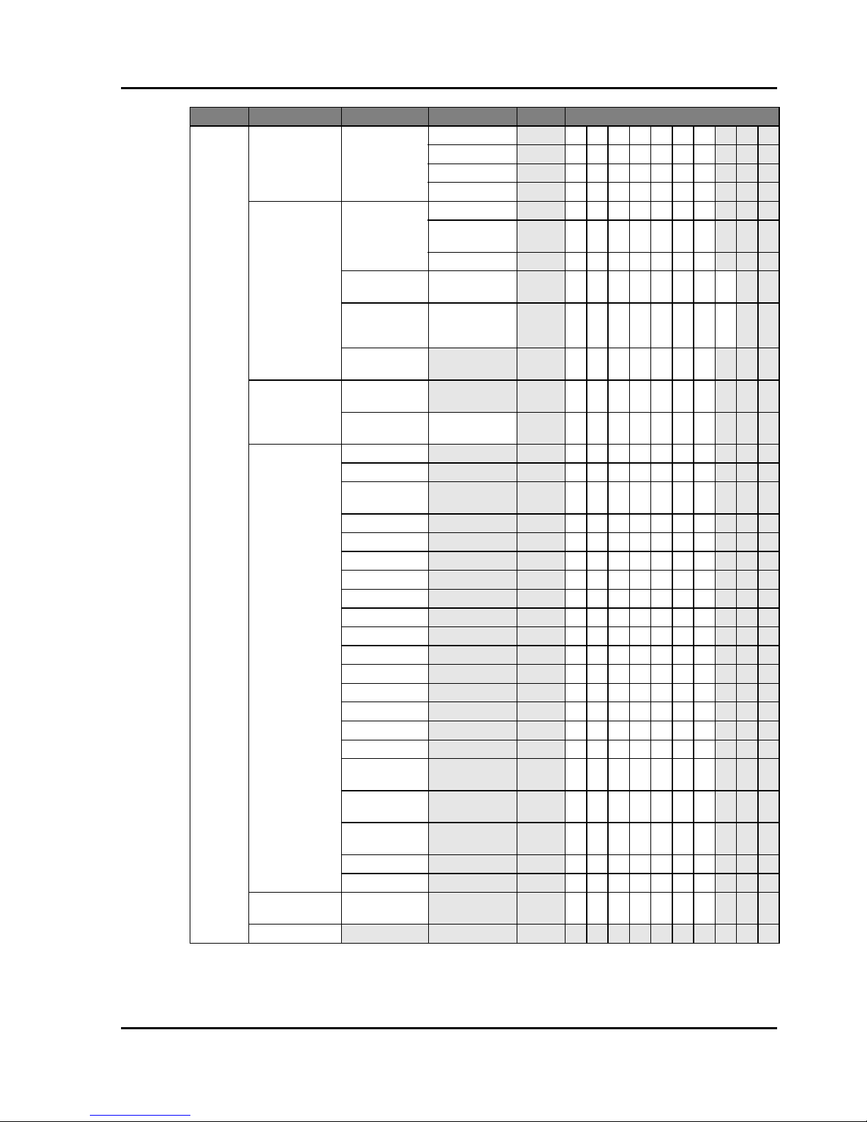
3.9 OSD Tree
Level 1 Level 2 Level 3 Level 4 Level 5 Uart CMD
PICTURE
Display Mode
Presentation [DPMO0 ]
Video [DPMO1 ]
Standard [DPMO2 ]
REC709 [DPMO3 ]
DICOM SIM [DPMO4 ]
2D High Speed [DPMO5]
3D [DPMO6 ]
Blending [DPMO7 ]
User [DPMO8 ]
Save to User [DPSU1]
Brightness 0 ~ 100 [BRIG*** ]
Contrast 0 ~ 100 [CONT* * * ]
Sharpness 0 ~ 4 [SHRP*]
Color 0 ~ 100 [COLR* * * ]
Tint 0 ~ 100 [TINT***]
Phase 0 ~ 100 [PHAS*** ]
Frequency 0 ~ 100 [CLCK** * ]
Horz Position 0 ~ 100 [HPOS** * ]
Vert Position 0 ~ 100 [VPOS*** ]
3D Display
3D Enable
Auto [TDEN0]
Frame Packing [TDEN1]
Side by Side [TDEN2]
Top and Bottom [TDEN3]
Frame
Sequential
[TDEN4]
Off [TDEN5]
3D Invert
Off [TDIV0]
On [TDIV1]
DLP Link
Off [TDDL0]
On [TDDL1]
HSG Adjustment
HSG Enable
Off [HGEN0 ]
On [HGEN1]
Auto Test
Pattern
Off [HGTP0 ]
On [HGTP1]
Red H. 0 – 254 [HGRH** * ]
Red S. 0 – 254 [HGRS** * ]
Red G. 0 – 254 [HGRG*** ]
Green H. 0 – 254 [HGGH** * ]
Green S. 0 – 254 [HGGS* * * ]
Green G. 0 – 254 [HGGG*** ]
Blue H. 0 – 254 [HGBH** * ]
Blue S. 0 – 254 [HGBS** * ]
Blue G. 0 – 254 [HGBG*** ]
Cyan H. 0 – 254 [HGCH** * ]
Cyan S. 0 – 254 [HGCS** * ]

Section 3: SPECIFICATIONS
Projector User Manual
3-9
PICTURE
HSG Adjustment
Cyan G. 0 – 254 [HGCG** * ]
Magenta H. 0 – 254 [HGMH*** ]
Magenta S. 0 – 254 [HGMS*** ]
Magenta G. 0 – 254 [HGMG** * ]
Yellow H. 0 – 254 [HGYH*** ]
Yellow S. 0 – 254 [HGYS*** ]
Yellow G. 0 – 254 [HGYG** * ]
White R Gain 0 – 254 [HGWR* ** ]
White G Gain 0 – 254 [HGWG*** ]
White B Gain 0 – 254 [HGWB*** ]
Reset to
Default
[HGRT1]
Advanced
White Peaking 0 - 100 [WHPK* * * ]
Gamma
VIdeo [GAMM0 ]
Film [GAMM1 ]
Bright [GAMM2 ]
CRT [GAMM3 ]
DICOM [GAMM4 ]
Gamma2.2 [GAMM5]
Color
Temperature
Warmest [CTMP0]
Warm [CTMP1]
Cool [CTMP2]
Bright [CTMP3]
Color Space
RGB [CSPA0]
REC709 [CSPA1]
REC601 [CSPA2]
RGB Video [CSPA3]
Auto [CSPA4]
Color Settings
Red Gain 0 ~ 100 [ R G A N * * * ]
Green Gain 0 ~ 100 [ G G A N * * * ]
Blue Gain 0 ~ 100 [ B G A N * * * ]
Red Offset 0 ~ 100 [ R O F S * * * ]
Green Offset 0 ~ 100 [ G O F S * * * ]
Blue Offset 0 ~ 100 [ B O F S * * * ]
Reset RGB
Gain/Offset
[RSGO1 ]
Color
Enhancement
0 ~ 2 [CLEH* ]
Color Wheel
Speed
2X [CWSP0]
3X [CWSP1]
Film Mode
Off [FLMO0]
On [FLMO1]
Extreme Black
Off [EXBK0]
On [EXBK1]
DynamicBlack™
Off [DYBK0]
On [DYBK1]
Level 1 Level 2 Level 3 Level 4 Level 5 Uart CMD
Section 3: SPECIFICATIONS
Projector User Manual
3-10
OUTPUT
Aspect Ratio
Auto [ASPR0]
4:3 [ASPR1]
16:9 [ASPR2]
16:10 [ASPR3]
Native [ASPR4]
Overscan
Off [OVSC0]
Zoom [OVSC1 ]
Crop [OVSC2]
H Digital Zoom 50% ~ 400% [HDZM** * ]
V Digital Zoom 50% ~ 400% [VDZM* * * ]
H Digital Shift 0 ~ 100 [HDSH** * ]
V Digital Shift 0 ~ 100 [VDSH* * * ]
Image Warping
PC Mode
Off [PCMO0]
On [PCMO1]
H Keystone 0 ~ 40 [ HKES * * ]
V Keystone 0 ~ 40 [ VKES * * ]
H Pincushion 0 ~ 100 [HPIC** * ]
V Pincushion 0 ~ 100 [VPIC*** ]
4-Corner
Top L e f t Hor z
Adjust
0 ~ 120
(pixel)
[TLCX***]
Top L e f t Ve r t
Adjust
0 ~ 80 [ T L C Y * * ]
Top Right Horz
Adjust
0 ~ 120 [ T R C X * * * ]
Top Right Vert
Adjust
0 ~ 80 [ T R C Y * * ]
Bottom Left
Horz Adjust
0 ~ 120 [ B L C X * * * ]
Bottom Left Vert
Adjust
0 ~ 80 [ B L C Y * * ]
Bottom Right
Horz Adjust
0 ~ 120 [ B R C X * * * ]
Bottom Right
Vert Adjust
0 ~ 80 [ B R C Y * * ]
PIP/PBP
PIP/PBP
Enable
Off [PIBP0]
On [PIBP1]
Main Source
VGA [MSRC0]
HDMI [MSRC1]
DVI-D [MSRC2]
HDBaseT [MSRC3]
LAN [MSRC4]
Sub Source
VGA [SSRC0]
HDMI [SSRC1]
DVI-D [SSRC2]
HDBaseT [SSRC3]
LAN [SSRC4]
Swap [PISW1]
Level 1 Level 2 Level 3 Level 4 Level 5 Uart CMD

Section 3: SPECIFICATIONS
Projector User Manual
3-11
OUTPUT PIP/PBP
Size
Small [PISZ0]
Medium [PISZ1]
Large [PISZ2]
Main Layout
PBP, Main Left [PILO0]
PBP, Main Top [PILO1]
PBP, Main Right [PILO2]
PBP, Main
Bottom
[PILO3]
PIP-Bottom
Right
[PILO4]
PIP-Bottom Left [PILO5]
PIP-Top Left [PILO6]
PIP-Top Right [PILO7]
SETUP
Language
English [LANG0]
French [LANG1]
Spanish [LANG2]
German [LANG3]
Italian [LANG4]
Russian [LANG5]
Chinese
Simplified
[LANG6]
Japanese [LANG7]
Korean [LANG8]
Portuguese [LANG9]
Indonesian [LANG10]
Dutch [LANG11]
Arabic [LANG12]
Ceiling Mount
Off [CEMO0]
On [CEMO1]
Auto [CEMO2 ]
Rear Projection
Off [REPJ0]
On [REPJ1]
Lens Function Focus
Focus
in motor
stop
[FCSI0]
Focus
in motor
go step
[FCSI1]
Focus
in motor
run
[FCSI2]
Focus
out motor
stop
[FCSO0]
Focus
out motor
go step
[FCSO1]
Level 1 Level 2 Level 3 Level 4 Level 5 Uart CMD

Section 3: SPECIFICATIONS
Projector User Manual
3-12
SETUP Lens Function
Focus
Focus
out motor
run
[FCSO2]
Zoom
Zoom in
- motor
stop
[ZOMI0]
Zoom in
- motor
go step
[ZOMI1]
Zoom in
- motor
run
[ZOMI2]
Zoom
out motor
stop
[ZOMO0]
Zoom
out motor
go step
[ZOMO1]
Zoom
out motor
run
[ZOMO2]
Lens Shift
Left
shift up
- motor
stop
[LSVU0]
Left
shift up
- motor
go step
[LSVU1]
Left
shift up
- motor
run
[LSVU2]
Left
shift
down motor
stop
[LSVD0]
Left
shift
down motor
go step
[LSVD1]
Left
shift
down motor
run
[LSVD2]
Left
shift
right motor
stop
[LSHR0]
Level 1 Level 2 Level 3 Level 4 Level 5 Uart CMD

Section 3: SPECIFICATIONS
Projector User Manual
3-13
SETUP
Lens Function
Lens Shift
Left
shift
right motor
go step
[LSHR1]
Left
shift
right motor
run
[LSHR2]
Left
shift left
- motor
stop
[LSHL0]
Left
shift left
- motor
go step
[LSHL1]
Left
shift left
- motor
run
[LSHL2]
Lens
Calibration
Yes/No (Dialog
box)
[LECA1]
Lens Lock
No [LELO0]
Ye s [LELO1]
Menu
Preferences
Menu
Transparency
0 ~ 9 [MNTP* ]
Show
Messages
Off [SMSG0]
On [SMSG1]
Keypad LED
Settings
Off [KLED0]
On [KLED1]
Pin
Pin Protect
Off [PINP*]
On [PINP*]
Change PIN [PINC*]
Communications
LAN
DHCP
Off [ L D H C 0 ]
On [ L D H C 1 ]
IP Address [ L I P A **************** ]
Subnet Mask [ L S U B **************** ]
Default
Gateway
[ L G A T **************** ]
MAC Address [LMAC?]
Apply [LAPY1]
WLAN
Enable
Off [ W L E N 0 ]
On [ W L E N 1 ]
Start IP [ W L S I **************** ]
End IP [ W L E I **************** ]
Subnet Mask [ W L S U **************** ]
Default
Gateway
[ W L G A **************** ]
MAC Address [WLMA? ]
SSID [WLSS? ]
Level 1 Level 2 Level 3 Level 4 Level 5 Uart CMD

Section 3: SPECIFICATIONS
Projector User Manual
3-14
SETUP Communications
Network
Projector Name [NPJN?]
Restart Network [NRST1]
Network
Factory Reset
[NFRS1]
Serial Port
Baud Rate
9600 [SPBR0]
14400 [SPBR1]
19200 [SPBR2]
38400 [SPBR3]
57600 [SPBR4]
115200 [SPBR5]
Serial Port Path
RS232 [ SPPA0 ]
HDBaseT [ SPPA1 ]
Projector
Address
0 - 9 [PJAD*]
OPTION
Auto Source
Off [ASRC0]
On [ASRC1]
High Altitude
Off [HIAL0]
On [HIAL1]
Test Pattern
Off [TPRN0]
Grid [TPRN1]
Red [TPRN2]
Green [TPRN3]
Blue [TPRN4]
Yel lo w [TPRN5]
Magenta [TPRN6]
Cyan [TPRN7]
White [TPRN8]
Black [TPRN9]
Background
Color
Logo [BGCL0]
Blue [BGCL1]
Black [BGCL2]
White [BGCL3]
Hot-Key settings
Blank Screen [HKST0]
Aspect Ratio [HKST1]
Freeze Screen [HKST2]
Overscan [HKST3]
Power Settings
Standby Power
Mode
0.5W mode [SBPM0]
Communication
mode
[SBPM1]
Direct Power
On
Off [DPON0 ]
On [DPON1]
Auto Power Off
No [APOF0]
5 Mins [APOF1]
10 Mins [APOF2]
15 Mins [APOF3]
20 Mins [APOF4]
25 Mins [APOF5]
30 Mins [APOF6]
Level 1 Level 2 Level 3 Level 4 Level 5 Uart CMD
Section 3: SPECIFICATIONS
Projector User Manual
3-15
OPTION
Power Settings Sleep Timer
No [SLTM0]
2 Hours [SLTM1]
4 Hours [SLTM2]
6 Hours [SLTM3]
Light Source
Settings
Light Source
Mode
Constant Power [LPMO0]
Constant
Luminance
[LPMO1]
Eco Mode [LPMO2]
Constant
Power Settings
0 – 99 [LPPW**]
Constant
Luminance
Settings
0 – 99 [LPAM**]
Total P roje c t or
Hours
[LPTH?]
Light Sensor
Light Sensor
Calibration
[LPCA1]
Calibrated?
(Display Yes/
No)
[LPCD?]
Information
Model Name [MDNA?]
Serial Number [SERI?]
Native
Resolution
[NRES?]
Firmware [FWVR?]
Main Source [MSRC?]
- Resolution [MSRS?]
- Signal Format [MSSF?]
- Pixel Clock [MSPC?]
- Horz Refresh [MSHR?]
- Vert Refresh [MSVR?]
Sub Source [SSRC?]
- Resolution [SSRS?]
- Signal Format [SSSF?]
- Pixel Clock [SSPC?]
- Horz Refresh [SSHR?]
- Vert Refresh [SSVR?]
Light Source
Mode
[LPMO?]
Total P roje c t or
Hours
[LPTH?]
Standby Power
Mode
[SBPM?]
IP Address [LIPA?]
DHCP [LDHC?]
Factory Reset
Yes/No (Dialog
box)
[FRST1]
Service
Level 1 Level 2 Level 3 Level 4 Level 5 Uart CMD

Section 4: INSTALLATION
Projector User Manual
4-1
4. INSTALLATION
4.1 Connect to Computer
NOTE:
The diagram shows the cables/connectors that may be used to connect to various devices.
Due to the difference in applications for each country, the accessories required in some regions may be different from those
shown.
This diagram is for illustrative purposes only, and does NOT indicate that these accessories are supplied with the projector.
Ind. Connector Name Ind. Connector Name
1 DVI Cable 6 Mini USB Cable
2 VGA in Cable 7 HDMI Cable
3 RS232 Cable 8 VGA out Cable
4 WIFI Dongle 9 Power Cord
5 HDMI Cable
Desktop
Laptop
1
2 3
4
5 6 7
9
8
External Display
Section 4: INSTALLATION
Projector User Manual
4-2
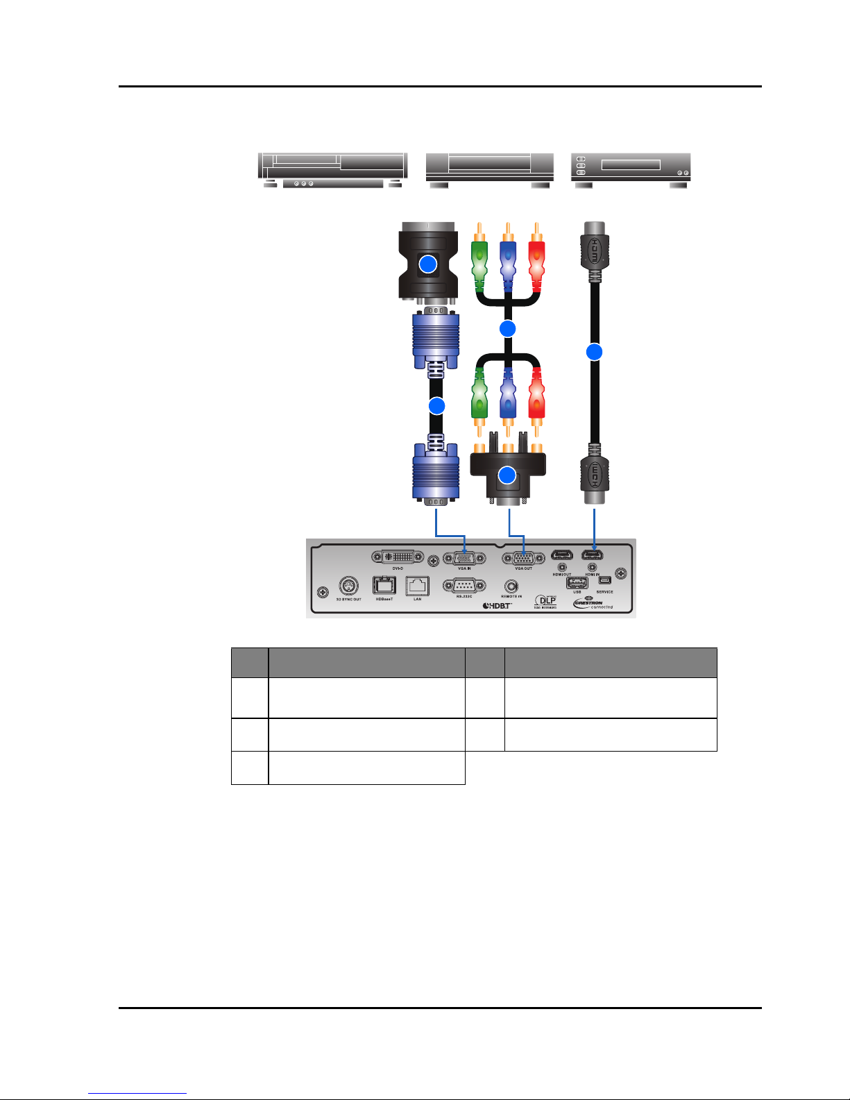
4.2 Connect to Video Equipment
NOTE:
The diagram shows the cables/connectors that may be used to connect to various devices.
Due to the difference in applications for each country, the accessories required in some regions may be different from those
shown.
This diagram is for illustrative purposes only, and does NOT indicate that these accessories are supplied with the projector.
Ind. Connector Name Ind. Connector Name
1 VGA to RBG SCART 4
15-pin to 3 RCA Component/
HDTV Adapter
2 VGA in Cable 5 HDMI Cable
3 3 RCA Component Cable
Component video output
equipment
DVD player
1
2
3
4
5
Video cassette recorder
Section 4: INSTALLATION
Projector User Manual
4-3
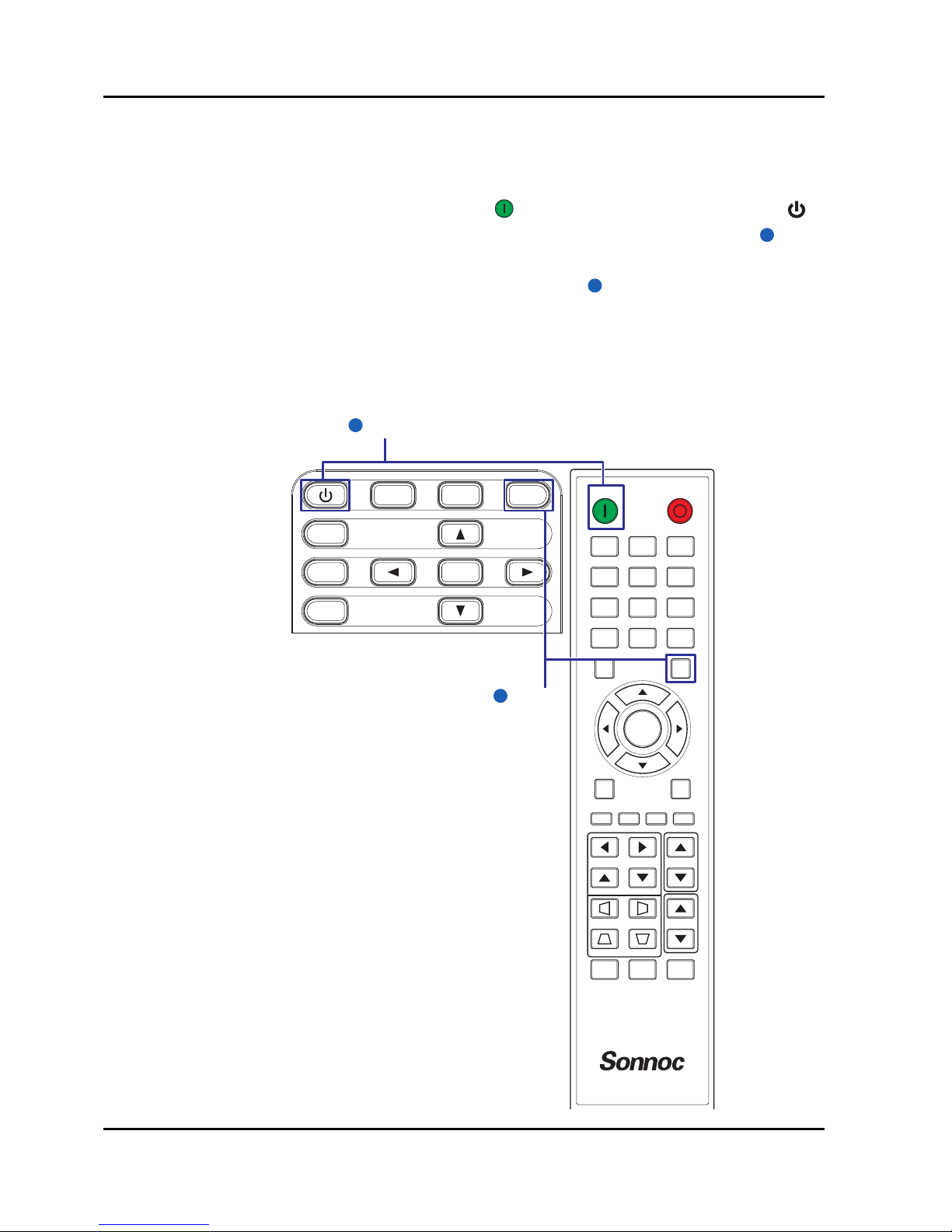
4.3 Turn the Projector On
1. Ensure that the power cord and signal cable are securely connected. The
Power button on the built in keypad is illuminated.
2. Turn on the projector by pressing " " on the remote control or press " "
on the built-in keypad. The Status LED is Orange with a long blink.
3. Turn on the source. Press the Input key on the remote control to select an
input source (VGA, HDMI, HDBaseT, or DVI).
4. The projector detects the source you selected and displays the image.
NOTE:
The first time the projector is used, the preferred language may be selected from the main menu after the startup screen is
displayed.
2
3
ON OFF
21 3
54 6
87 9
Gamma Bright Cont. PIP
0
Info
Mode
Auto
Input
Menu Exit
Hot Key
Shutter
(AV Mute)
Pattern
Focus
Lens H
Lens V
Keystone H
Keystone V
Zoom
Enter
MENU INPUT
EXIT
LENS
FOCUS
ZOOM
ENTER
Power on
2
Input Key
3

Section 4: INSTALLATION
Projector User Manual
4-4
4.4 Turn the Projector Off
1. Press " " on the built-in keypad or press " " on the remote control to turn
off the projector. A warning message will appear on the displayed image.
2. Press " " on the built-in keypad or press " " on the remote control again
to confirm your selection. If you do not press " " or " " again, the warning
message will disappear after 10 seconds.
4.5 Adjust the Projector Position
When you select a position for the projector, consider the size and shape of
your screen, the location of your power outlets, and the distance between the
projector and the rest of your equipment. Follow these general guidelines:
• Position the projector on a flat surface at a right angle to the screen. The
projector (with the standard lens) must be at least 3 feet (0.9m) from the
projection screen.
• Position the projector to the desired distance from the screen. The distance
from the lens of the projector to the screen, the zoom setting, and the video
format determine the size of the projected image.
• For the fixed short lens, the image exits at a default angle. However, the
lens shift feature makes the image offset variable.
• Lens throw ratio:
- A01: 1.00-1.28 (WXGA) / 0.95-1.22 (WUXGA)
- A03: 1.60-3.07 (WXGA) / 1.52-2.92 (WUXGA)
- A06: 1.28-1.61 (WXGA) / 1.22-1.53 (WUXGA)
- A13: 3.04-5.78 (WXGA) / 2.90-5.50 (WUXGA)
- A15: 0.79-1.00 (WXGA) / 0.75-0.95 (WUXGA)
• 360 degree free orientation operation

Section 4: INSTALLATION
Projector User Manual
4-5
4.6 Lens Offset
A06 is the standard lens for WXGA and WUXGA.
Projection Lens A01 A03 A06 A13 A15
Focal Length (f) 14.03-17.96 22.56-42.87 18.07-22.59 42.60-80.90 11.11-14.06
F number 2.30-2.57 2.30-3.39 2.00-2.32 2.30-2.74 2.30-2.53
Focus spec (MTF) 67 lp/mm 67 lp/mm 67 lp/mm 67 lp/mm 67 lp/mm
Zoom Range(Ratio) 1.28X 1.9X 1.25X 1.9X 1.26X
Zoom & Focus
Adjustment
Motorized
Throw Ratio (WXGA) 1.00-1.28 1.60-3.07 1.28-1.61 3.04-5.78 0.79-1.00
Throw
Distance(WXGA)
1.08-8.27m 1.72-19.84m 1.38-10.40m 3.27-37.35m 0.83-6.45m
Throw Ratio (WUXGA) 0.95-1.22 1.52-2.92 1.22-1.53 2.90-5.50 0.75-0.95
Throw
Distance(WUXGA)
1.02-7.88m 1.64-18.87m 1.31-9.89m 3.12-35.54m 0.81-6.13m
Projection Image Size 50~300”
Motorized Lens Shift
(Lens shift range
based on 1/2 screen
width and height)
Horizontal: +/-30%
Vertical: +/-100%
Projection Lens: A01, A03, A13
Projection Lens: A06
Platform H V H V
0.65" WXGA 30% 100% 30% 100%
0.67"WUXGA 30% 100% 30% 100%
Platform H V H V
0.65" WXGA 30% 100% 30% 100%
0.67"WUXGA 30% 100% 20% 80%

Section 4: INSTALLATION
Projector User Manual
4-6
Motorized Lens Shift
(Lens shift range
based on 1/2 screen
width and height)
Projection Lens: A15
A01, A03, A13 lens shift range:
A06, A15 lens shift range:
Lens shift accuracy: 0.5 pixel per step.
When the lens is shifted beyond the described range of operation, the
screen edges may become darker or the images may become out of
focus.
Projection Lens A01 A03 A06 A13 A15
Platform H V H V
0.65" WXGA 30% 100% 14% 70%
0.67"WUXGA 30% 100% 2% 50%
Lens shift range
Lens shift range
Darker
Section 4: INSTALLATION
Projector User Manual
4-7
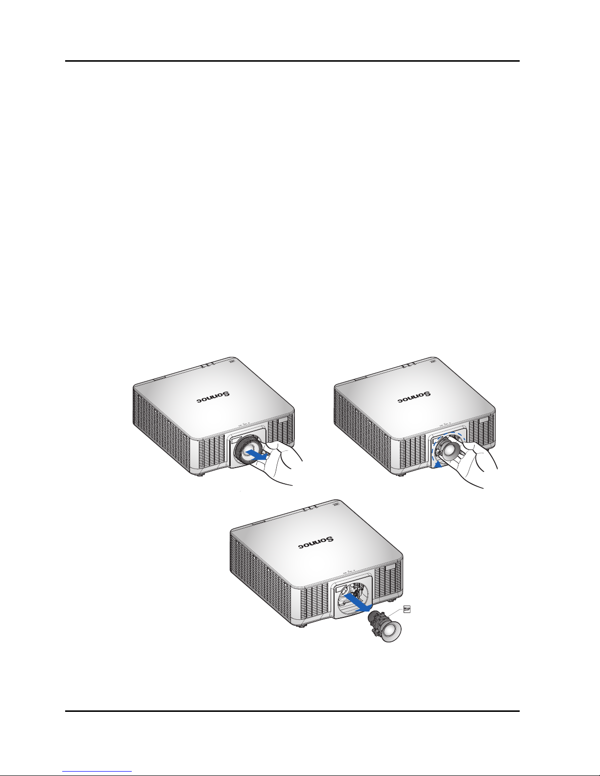
4.7 Removing and Installing the Lens
When handling the projector after lens installation, make sure the front lens
cap is placed on the lens to protect the lens surface from potential damage.
When carrying or moving the projector, do not handle by the lens. This may
damage the lens, the chassis or other mechanical parts within the projector.
Installation Steps:
1. Center the lens: Ensure that the lens is at or near its center position.
Attempting to remove the lens when at a large offset may cause damage to
the lens assembly. Center the lens while the projector is switched on by
pressing the lens horizontal or vertical button and then pressing Enter.
2. Turn Off the projector: Turn the projector OFF.
3. Wait for projector to cool down: Allow the projector to cool down into
standby mode before replacing the lens. Remove power cord after the
projector has cooled down and prior to replacing the lens.
4. Remove the lens: Remove the lens ring. Rotate the lens counterclockwise to disengage it from the lens mount. Remove the lens out of the
lens mount.
5. Install the new lens: With the label “TOP” on the lens assembly facing up,
install the assembly into the lens mount. Rotate the lens clockwise to lock
the lens in place. Firmly install the lens ring onto the lens.
Section 5: OPERATION
Projector User Manual
5-1
5. OPERATION
The projector has multilingual On-Screen Display (OSD) menus that allow you
to make image adjustments and change a variety of settings.
• Most of the projector controls are accessed from within the projector menu
system. There are several groups of related functions, with each group
selectable from the Main menu as shown below. Press the MENU button on
the remote control or on the built-in keypad on the rear of the projector to
display the main menu.
• Use the arrow keys to navigate within the menu and adjust a setting up or
down.
• Press ENTER to select a highlighted menu item or use it to change or
accept a value.
• Select the next item that you want to adjust in the menu and adjust it as
described above.
• Press EXIT to return to the previous menu or exit menus if at top level.
NOTE:
If the text is gray color, user is unable to enter the menu when the projector does not detect any input source.
If the text is white color, user is able to select the menu when the projector does not detect any input source.
PICTURE
Display Mode
Brightness
Contrast
Sharpness
Color
Tint
Phase
Frequency
Horz Position
Vert Position
PICTURE
OUTPUT
SETUP
OPTION
Presentation
50
50
2
50
50
50
50
50
50
Section 5: OPERATION
Projector User Manual
5-2
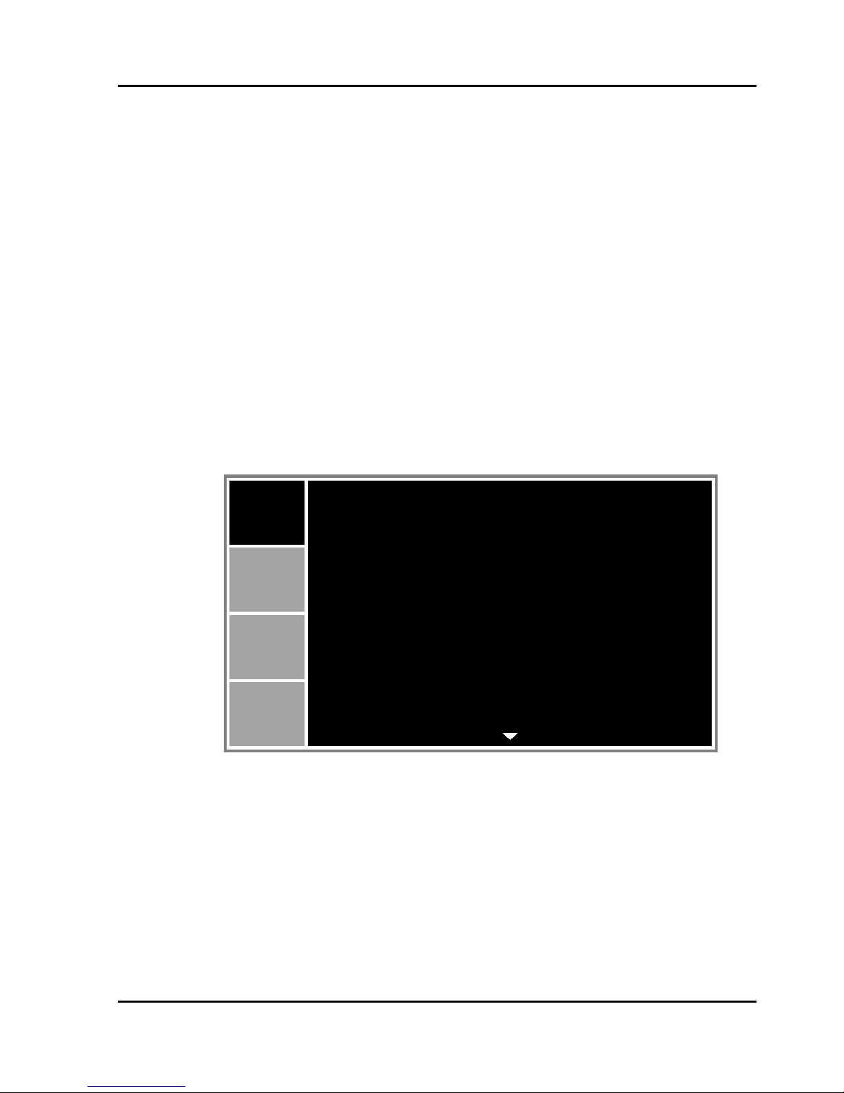
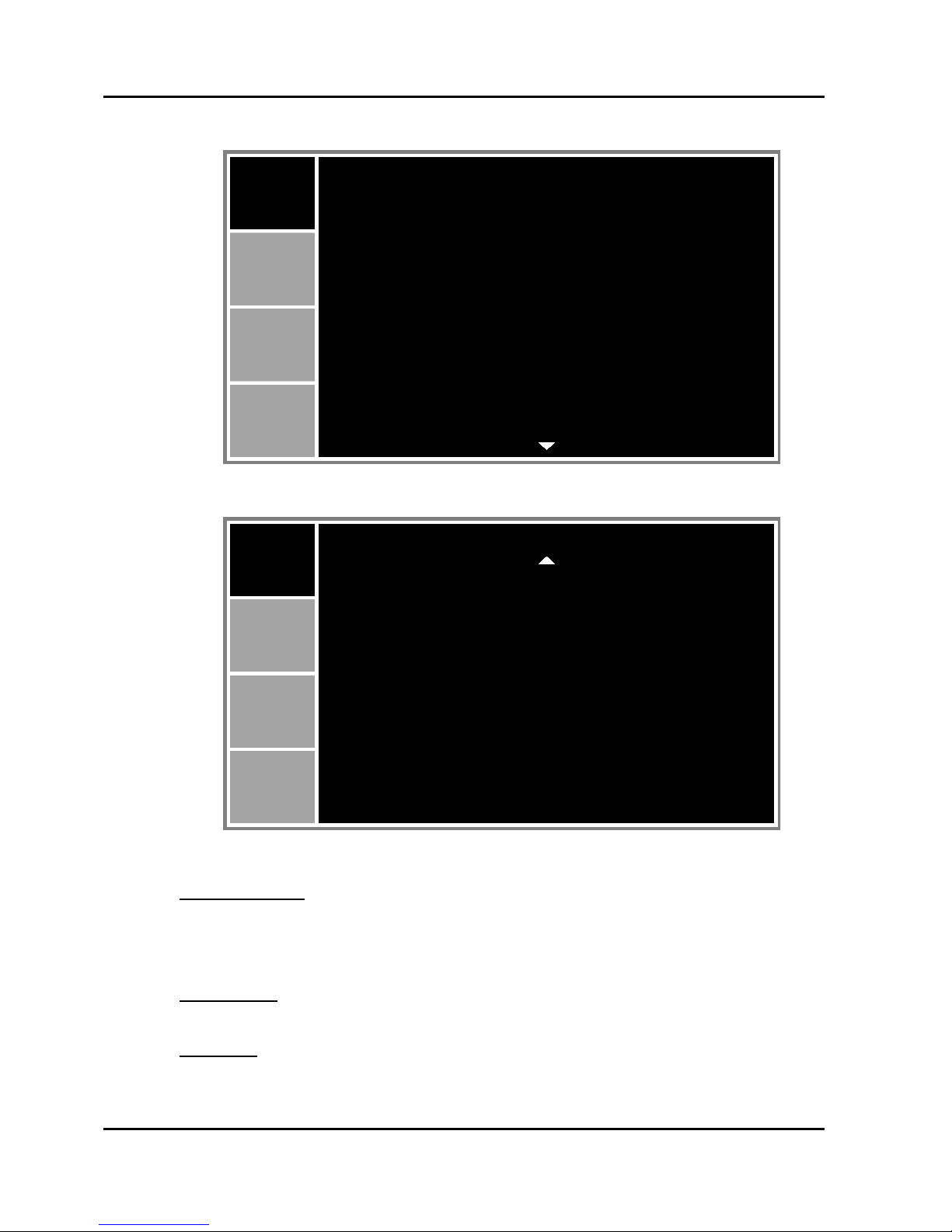
5.1 Picture Menu
PICTURE (1/2)
PICTURE (2/2)
Display Mode
Optimize the projector for displaying images under certain conditions, such as
Presentation, Video, Standard, REC709, DICOM SIM, 2D High Speed, 3D,
Blending, and user-definable preset.
Brightness
Adjust the intensity of the image.
Contrast
Adjust the degree of difference between the lightest and darkest parts of the
picture and change the amount of black and white in the image.
PICTURE
PICTURE
OUTPUT
SETUP
OPTION
Display Mode
Brightness
Contrast
Sharpness
Color
Tint
Phase
Frequency
Horz Position
Vert Position
Presentation
50
50
2
50
50
50
50
50
50
PICTURE
3D Display
HSG Adjustment
Advanced
PICTURE
OUTPUT
SETUP
OPTION

Section 5: OPERATION
Projector User Manual
5-3
Sharpness
Select the edge clarity of the image.
Color
Adjust a video image from black and white to fully saturated color. The color
setting applies to video sources only.
Tint
Adjust the red-green color balance in the image of video images. The tint
setting applies to video sources only.
Phase
Analog signals only. Adjust pixel phase when the image still shows shimmer or
noise after pixel tracking is optimized. Pixel phase can adjust the phase of the
pixel-sampling clock relative to the incoming signal.
Frequency
Analog signals only. Steady flickering or several soft vertical stripes or bands
across the entire image indicates poor frequency. Proper frequency ensures
that the image quality is consistent across the screen, the aspect ratio is
maintained, and that the pixel phase can be optimized.
Horz Position
Move the image right or left within the area of available pixels.
Vert Position
Move the image up or down within the area of available pixels.
3D Display
Select the 3D relating settings.
• 3D Enable: Set 3D format. Supports Mandatory 3D formats and frame
sequential 3D@120Hz.
• 3D Invert: Invert 3D sync signal for the application of using single projector.
• DLP Link: Select 3D Sync source:
- On: 3D Sync type is DLP link.
- Off: 3D Sync source is from the 3D SYNC OUT port.

Section 5: OPERATION
Projector User Manual
5-4
HSG Adjustment
Configure the color management settings.
• HSG Enable: Enable/Disable the HSG adjustment function.
• Auto Test Pattern: Set to “On” to enable displaying a test pattern for the
target color or set to “Off” to disable the auto test pattern.
• Red H. / Green H. / Blue H. / Cyan H. / Magenta H. / Yellow H.: Adjust the
hue of the red, green, blue, cyan, magenta, or yellow channel of the image.
• Red S. / Green S./ Blue S. / Cyan S./ Magenta S./ Yellow S.: Adjust the
saturation of the red, green, blue, cyan, magenta, or yellow channel of the
image.
• Red G. / Green G. / Blue G. / Cyan G. / Magenta G. / Yellow G.: Adjust the
gain of the red, green, blue, cyan, magenta, or yellow channel of the image.
• White R Gain / White G Gain / White B Gain: Adjust the white balance of
the red, green, or blue channel of the image.
• Reset to Default: Reset the hue, saturation, gain, and white balance
adjustments to the factory defaults.
Advanced
• White Peaking: (Video source only) Increase the brightness of whites that
are near 100%.
• Gamma: Select the appropriate gamma from Video, Film, Bright, CRT,
DICOM, and Gamma 2.2.
• Color Temperature: Change the intensity of the colors.
• Color Space: Select a color space that has been specifically tuned for the
input signal. Use only for analog signals and certain digital sources.
• Color Settings: Adjust the gain of the red, green, or blue channel of the
image. It will affect the black and white.
Adjust the offset of the red, green, or blue channel of the image. It will affect
the black and white.
Reset RGB gain/offset to return the factory default settings for color
adjustments.
• Color Enhancement: Apply the color enhancement process.
• Color Wheel Speed: Higher speed will reduce the appearance of color
artifacts seen by some people.
• Film Mode: Control film mode detection and determine whether the original
source of the input video was film or video.
• Extreme Black: Analyze the current input image and calculate an offset
value which is then added to the analog to digital converter black level
value. This ensures optimum black level for each analog source.
• DynamicBlack™: Automatically adjust the contrast ratio for video contents.

Section 5: OPERATION
Projector User Manual
5-5
5.2 Output Menu
Aspect Ratio
Display an image with the detected size, or resize the image by maximizing
either the height, width or both, or resize to the maximum size possible while
keeping the original aspect ratio.
• Auto: Display with the detected size.
• 4:3: Retain 4:3 aspect ratio.
• 16:9: Retain 16:9 aspect ratio.
• 16:10: Retain 16:10 aspect ratio.
• Native: Display in its native resolution.
Overscan
Remove noise around the image. Overscan Zoom enlarges image 3% from
original size. Overscan Crop cuts 3% of active pixels in four edges of original
image.
H Digital Zoom
Change the size of projector's display area horizontally. If the display area has
been resized by this setting, it can be moved by changing the H Digital Shift
and V Digital Shift settings.
V Digital Zoom
Change the size of projector's display area vertically. If the display area has
been resized by this setting, it can be moved by changing the H Digital Shift
and V Digital Shift settings.
H Digital Shift
Move the display area horizontally if its size has been changed by the Digital
Zoom setting.
OUTPUT
Aspect Ratio
Overscan
H Digital Zoom
V Digital Zoom
H Digital Shift
V Digital Shift
Image Warping
PIP/PBP
PICTURE
OUTPUT
SETUP
OPTION
Auto
Off
100
100
50
50

Section 5: OPERATION
Projector User Manual
5-6
V Digital Shift
Move the display area vertically if its size has been changed by the Digital
Zoom setting.
Image Warping
• H Keystone: Adjust the keystone horizontally and make a squarer image.
Horizontal keystone is used to correct a keystoned image shape in which
the left and right borders of the image are unequal in length. This is
intended for use with horizontally on-axis applications.
• V Keystone: Adjust the keystone vertically and make a squarer image.
Vertical keystone is used to correct a keystoned image shape in which the
top and bottom are slanted to one of the sides. This is intended when for
use with vertically on-axis applications.
• H Pincushion: Adjust the pincushion horizontally and make a more square
image.
• V Pincushion: Adjust the pincushion vertically and make a more square
image.
Ind. WXGA WUXGA
A 12.3% 7.1%
B7.7%5.2%
B
A
B
A
Ind. WXGA WUXGA
A5.4% 3.3%
B 10% 5.4%
B
A
B
A
Ind. WXGA WUXGA
A 16.0% 8.0%
B 16.0% 7.9%
A B
Ind. WXGA WUXGA
A 14.7% 11.4%
B 14.7% 11.4%
A B

Section 5: OPERATION
Projector User Manual
5-7
• 4-Corner: Allow the image to be squeezed to fit an area defined by moving
each of the four corners’ x and y position.
PIP/PBP
• PIP/PBP Enable: Toggle between displaying two sources at once (Main
and PIP/PBP images) or one source only.
• Main Source: From the list of active inputs, select one to be used as the
main image.
• Sub Source: From the list of active inputs, select one to be used as the PIP/
PBP.
• Swap: Change the main image to PIP/PBP, and the PIP/PBP to main
image. Swapping is available only when PIP/PBP is enabled.
• Size: Select the PIP/PBP size. Available options: Small, Medium, or Large.
• Main Layout: Set the location of the PIP/PBP image on the screen.
NOTE:
PIP/PBP layout and size table as described below.
P : indicates primary source region (lighter color).
* : Both source regions are the same size.
PIP/PBP Main Layout
PIP/PBP Size
Small Medium Large
PBP, Main Left
*
PBP, Main Top
PBP, Main Right
PBP, Main Bottom
PIP-Bottom Right
A A
B
B
B
B
AA
P
P
P
P
P
P
P
P
P
P
P
P
PPP
*
*
*
*

Section 5: OPERATION
Projector User Manual
5-8
PIP-Bottom Left
PIP-Top Left
PIP-Top Right
PIP/PBP Main Layout
PIP/PBP Size
Small Medium Large
P
P
P
P
P
P
P
P
P

Section 5: OPERATION
Projector User Manual
5-9
5.3 Setup Menu
Language
This item allows you to select an available language for the OSD display.
Ceiling Mount
Turn the image upside down for ceiling-mounted projection.
Rear Projection
Reverse the image so you can project from behind a translucent screen.
Lens Function
• Focus: Adjust focus function on the projected image.
• Zoom: Adjust zoom function on the projected image.
• Lens Shift: Shift the projected image.
• Lens Calibration: Perform calibration and return lens to the center position.
• Lens Lock: Select this function to prevent all lens motors from moving.
- No: Lens shift can be used by user.
- Yes: Lens shift will be locked.
Menu Preferences
• Menu Transparency: Change OSD menu background to be transparent.
• Show Messages: Display status messages on the screen.
Keypad LED Settings
• Off: Turn off the backlight of the keypad.
• On: Turn on the backlight of the keypad.
SETUP
Language
Ceiling Mount
Rear Projection
Lens Function
Menu Preferences
Keypad LED Settings
Pin
Communications
PICTURE
OUTPUT
SETUP
OPTION
English
Auto
Off
On

Section 5: OPERATION
Projector User Manual
5-10
Pin
• PIN Protect: The PIN (personal identification number) feature allows you to
password protect your projector. Once you enable the PIN feature, you
must enter the PIN before you can project an image. (PIN Default : 12345)
• Change PIN: This item allows you to change the PIN.
Communications
• LAN:
- DHCP: Turn the DHCP ON/OFF.
- IP Address: Assign Network IP Address.
- Subnet Mask: Assign Network Subnet Mask.
- Default Gateway: Assign Network Default Gateway.
- MAC Address: Display the network MAC Address value.
- Apply: Apply Network settings.
• WLAN:
- Enable: Enable/Disable WLAN.
- Start IP: Start of IP Address.
- End IP: End of IP Address.
- Subnet Mask: Assign Network Subnet Mask.
- Default Gateway: Assign Network Default Gateway.
- MAC Address: Display network MAC Address value.
- SSID: Assign Network Service Set Identifier.
• Network:
- Projector Name: Display the projector hostname for Network.
- Restart Network: Restart the network.
- Network Factory Reset: Perform factory reset on the network settings.
The Projector Name and network configuration settings will be reset.
• Serial Port Baud Rate: Select the serial port and baud rate.
• Serial Port Path: Select the serial port path from either RS232 or HDBaseT.
• Projector Address: Set the projector address. The projector will respond to
IR remotes set either at the same address as the projector or to IR remotes
set to address 0.
Section 5: OPERATION
Projector User Manual
5-11
5.4 Option Menu
OPTION (1/2)
OPTION (2/2)
Auto Source
• Off: The projector will only search current input connection.
• On: The projector will search for other signals if the current input signal is
lost.
High Altitude
Set high altitude mode On/Off. When On, the fan will operate at high speed to
ensure sufficient air flow for high altitudes.
OPTION
Auto Source
High Altitude
Test Pattern
Background Color
Hot-Key settings
Power Settings
Light Source Settings
Light Sensor
PICTURE
OUTPUT
SETUP
OPTION
Information
Factory Reset
On
Off
Off
Logo
Blank Screen
OPTION
Service
PICTURE
OUTPUT
SETUP
OPTION

Section 5: OPERATION
Projector User Manual
5-12
Test Pattern
Choose the desired internal test pattern to display, or select Off to turn off a test
pattern.
Background Color
Use this feature to display a “Logo”, “Blue”, “Black” or “White” screen when no
signal is available.
Hot-Key settings
Assign a different function to the hot-key on the remote control by highlighting
the function in the list and pressing ENTER. Choose a function that does not
already have a dedicated button, and assign the hot-key to that function,
allowing you to quickly and easily use the chosen function.
Power Settings
• Standby Power Mode:
- 0.5W mode: The projector is in standby mode when connected to AC
power. (<0.5W)
- Communication mode: The projector could be controlled via the LAN
terminal during power standby.
• Direct Power On: The projector automatically turns on when electrical
power is connected.
• Auto Power Off: Automatically turns the projector off after no signals are
detected for a preset number of minutes. If an active signal is received
before the projector powers down, the image will be displayed.
• Sleep Timer: This item allows the projector to automatically power off after
it has been on for a specified amount of time.
Light Source Settings
• Light Source Mode: Select Constant Power, Constant Luminance or Eco
Mode. When in Eco Mode, the projector will adjust to the lowest fan speed
and switch the laser diode power to the minimum setting.
• Constant Power Settings: Set the value of the laser diode power (in Watts).
• Constant Luminance Settings: Set the value for the Constant Luminance
Settings to maintain constant brightness. The light sensor will monitor the
light level and will apply more power as the laser brightness decays
naturally over time. When the laser setting reaches maximum power, it will
remain at this setting. Note that the light sensor needs to be calibrated for
Constant Luminance mode to work properly.
• Total Projector Hours: Display current total hours the projector used.

Section 5: OPERATION
Projector User Manual
5-13
Light Sensor
• Light Sensor Calibration: Calibrate the Light Sensor for use with the
Constant Luminance mode, which allows the projector to be set for
constant brightness. If the Light Sensor has not been calibrated, Constant
Luminance mode will be disabled.
• Calibrated:
- Yes: Light Sensor has been calibrated.
- No: Light Sensor has not been calibrated.
Information
Display the projector information for source, resolution, and software version
on the screen.
Factory Reset
Restore all settings to their default value. It will not reset network.
Service
Service only.

www.sonnoc.com
Manufacturer: Sonnoc (Beijing) Technology Co., Ltd.
Address: Room 806, Floor 7, Building 5, Desheng Zhiye Building, No 26 Huangsi Street,
Xicheng District, Beijing 100120, China Postcode:100120
Fax: 010-82075080
Tel: 400-898-5
 Loading...