

Page 1

Sonnet Web Management Tool
User’s Guide
for Fusion Fibre Channel Storage Systems
Page 2

Page 3

Contents
1.0 Getting Started......................................................................................................................... 1
Discovering the IP address
Optional - Setting up Internet Explorer
Beginning Initial Configuration
1.1 Ensure Drive Integrity............................................................................................................... 3
Before Creating RAID Groups
After Creating R AID Groups
1.2 Configure Storage into RAID Groups.......................................................................................... 7
Features You May Choose
Auto-Rebuild
Fault Tolerance
Initialization
Selecting a Quick Storage Configuration
Preliminary Steps
Quick Digital Video
Audio
General Digital Video, General IT or Database
Creating a Custom Setup
Mac OS Drive Formatting
Windows Drive Formatting
1.3 Modify System Values............................................................................................................. 17
Changing the Current User Name, Password
Creating a Read-Only User Name, Password
Changing System Variables - System Configuration
1.4 Monitor Storage, Configurations.............................................................................................. 19
Health and Status Monitor Page
Configuration Display Page
SCSI Enclosure Services (SES)
1.5 Remote System Monitoring...................................................................................................... 21
Types of Errors
Warning messages
Message Severity Levels
Email Notification Setup
1.6 Drive Diagnostics....................................................................................................................23
Preliminary Steps
Read-Only Drive Test
Drive Performance and Health Test
Identifying a Drive
Page 4

Contents
1.7 SCSI Enclosure Services(SES)................................................................................................... 27
Setting up SES
Identifying SES Elements
Monitoring SES Elements Using the Health and Status Monitor
1.8 Modify Storage....................................................................................................................... 31
Preliminary Steps
RAID Group Processes
Creating RAID Groups
Deleting RAID Groups
Adding Drives to a R AID Group
Adding Mirrors to a RAID Configuration
Changing RAID Configuration: RAID Migration
Modifying R AID Group Mapping
Modifying R AID Group Partitions
Rebuilding RAID Groups
Modifying R AID Options
Adding or Removing Hot Spares
Removing RAID Configuration Data
Advanced CLI Page
2.0 Manage Sonnet Devices, Configurations................................................................................... 43
Creating a Unique Name for Your RX1600Fibre
Discovering, Managing Other Sonnet Devices
Saving or Restoring a Configuration
2.1 Interface Options.................................................................................................................... 47
Using the ExpressNAV Storage Manager
Using the Serial Port
Using Telnet
2.2 Update Firmware.................................................................................................................... 49
Appendix A - CLI ASCII-Based Interface........................................................................................... i
CLI Error Messages
CLI Summary
CLI Command Explanations
Appendix B - RAID Group Designs................................................................................................. xix
JBOD: Just a Bunch of Disks
RAID Level 0: Striping, No Redundancy
RAID Level 1: Mirroring (Duplicate Drives)
RAID Level 1 Plus Additional Mirroring
RAID Level 1+0: Striping, Mirror Spans Two Drives
RAID Level 4: Striping, One Parity Drive
DVRAID: Digital Video RAID
RAID Level 5: Striping, Parity Distributed Among Drives
RAID Level 6: Striping, Two Parity Blocks Distributed Among Drives
Page 5

Contents
Appendix C - Multipathing.......................................................................................................... xxiii
Mac OS Users’ Instructions
Mac OS Users’ Instructions
Mac OS Users’ Instructions
Appendix D - Quick Drive Reformat Instructions........................................................................... xxv
Mac OS Users’ Instructions
Windows Vista Users’ Instructions
Windows XP/Server 2003 Users’ Instructions
Page 6

Page 7

1.0 Getting Started
Discovering the IP address
The Fusion RX1600Fibre is initially configured with DHCP enabled. It
is best if you have access to a DHCP server.
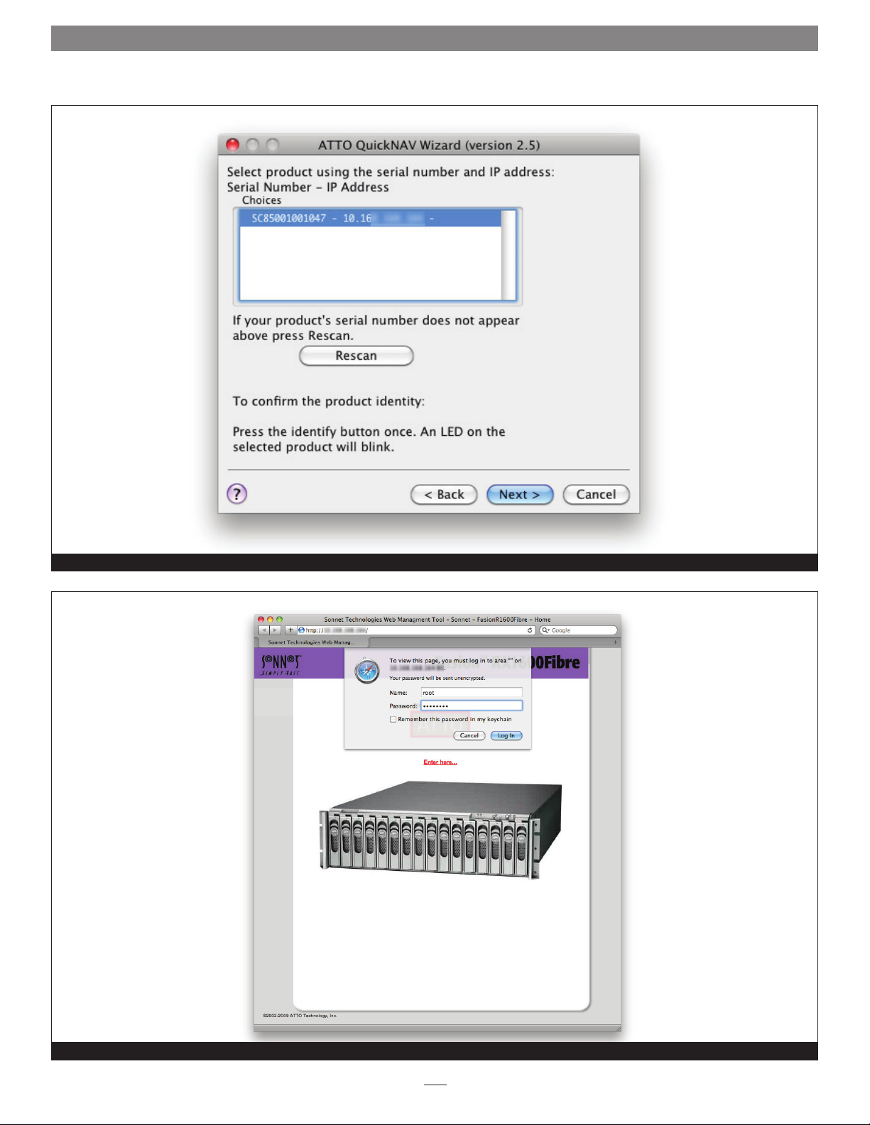
1. Work from the computer attached to the RX1600Fibre’s
Ethernet port. From the CD supplied with your RX1600Fibre,
run the QuickNav Utility QuickNAV-windows.exe for
Windows or QuickNAV-Mac for Mac OS X.
2. Locate the RX1600Fibre with the serial number recorded
earlier.
3. Highlight the serial number.
4. Click Next. If a DHCP server is available on your network,
an address is assigned automatically by the server. Note the
assigned address. If you do not have a DHCP server, get an IP
address and subnet mask from your network administrator,
type it into the area provided, and click Next. See Figure 1
on page 2.
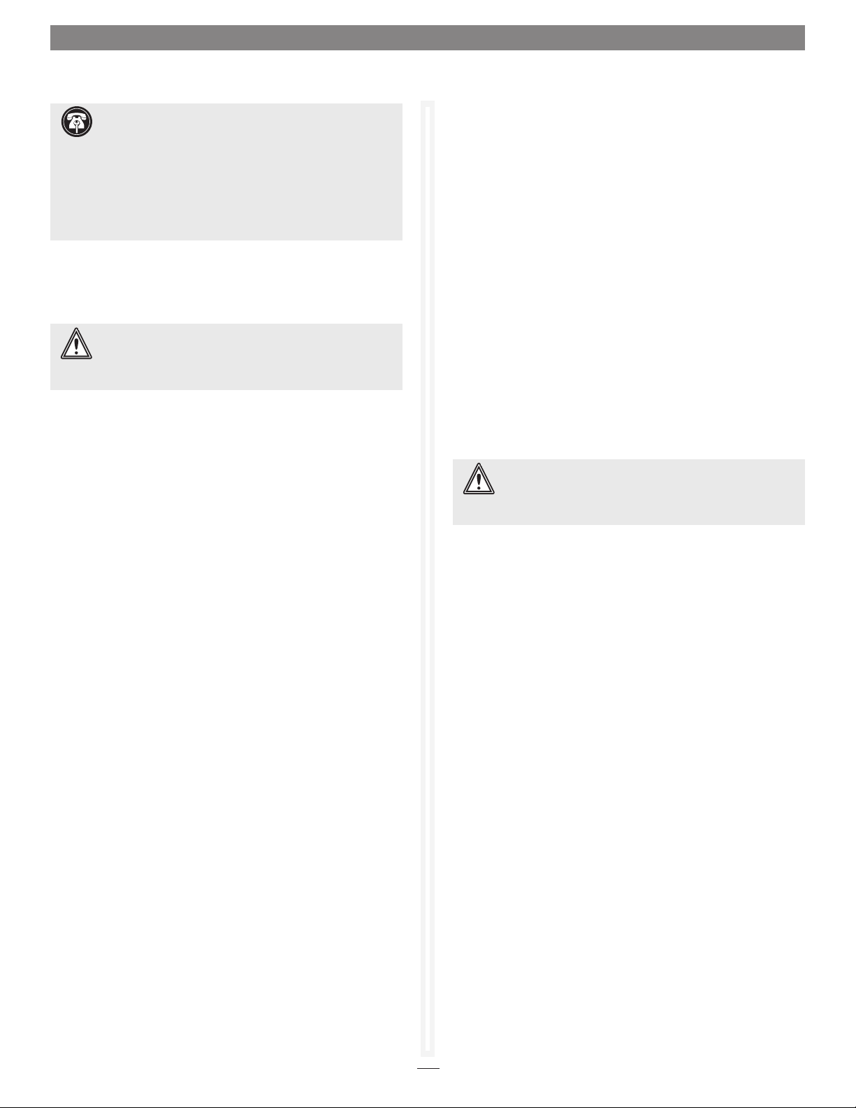
5. Click Launch Browser. Your browser points to the Sonnet
Web Management Tool splash screen.
Optional - Setting up Internet Explorer
If you use Internet Explorer as a browser, you must configure it to
work with the Sonnet Web Management Tool. If not, continue on to
Beginning Initial Configuration.
Beginning Initial Configuration
1. The Sonnet Web Management Tool interface splash screen
appears. Click Enter Here. See Figure 2 on page 2.
2. Type in the user name and password.
Note: The default values are user name root and password Password.
The user name is case insensitive and the password is case
sensitive. It is best practice to change the default user
name and password. Refer to Changing the Current User
Name, Password on page 17.
3. If the Fusion RX1600 was shipped from Sonnet with
hard drives preinstalled, the Health and Status Monitor
page appears. Otherwise, the Initial Setup page appears.
Continue to Ensure Drive Integrity on page 3.
1. Open your browser.
2. Select Internet Options.
3. In the Internet Options screen, select the Security tab.
4. Click the Trusted Sites icon.
5. Click the Sites button.
6. In the text box Add this Web site to the zone, add the IP
address of the controller. You may use wild cards.
7. Click Add.
8. Uncheck the Require server verification checkbox.
9. Click OK.
10. At the bottom of the Internet Options box, click OK and
close the box.
1
Page 8
1.0 Getting Started
Using the QuickNav application to find the IP address for the RX1600Fibre
Figure 1
The Sonnet ExpressNav Storage Manager splash screen with login
Figure 2
2
Page 9
1.1 Ensure Drive Integrity
Support Note: In Fusion RX1600 systems shipped from
Sonnet with hard drives installed, the drives are formatted
Mac OS Extended (Journaled), configured as a single RAID 6 RAID
group, and ready for use with Mac OS X-based systems. If you
need to change the configuration, delete the existing RAID group
(see Deleting RAID Groups on page 31), and use the Sonnet Web
Management Tool and the operating system software tools to
reformat and reconfigure the drives. See Appendix D for Quick
Drive Reformat instructions for Mac OS and Windows users.
The ATTO FastStream “Initialize and Verify Drives” feature discovers
and remaps bad sectors on drives, providing reliable media for your
RAID groups.
WARNING: Selecting Drive Initialization causes all
previous storage data on the drive to be erased. Make
sure all of your information is backed up before initializing
drives.
Before creating any RAID group you should initialize and verify
the drives you want in the RAID group to ensure drive integrity.
When selected, the FastStream writes a pattern to the entire drive,
verifying the drive’s readiness and reliability.
During initialization and verification, the FastStream collects
performance measurements. Performance data is available
once initialization begins. You may view it from the Drive
Performance and Health page accessible from the Diagnostics
menu. This performance data is lost when the controller is
powered off.
Before Creating RAID Groups
1. If you’re not already in the Sonnet Web Management Tool,
type the IP address of your RX1600Fibre in a standard
browser. On the splash screen, click Enter Here. In the box
provided, type in your user name and password, and then
click OK.
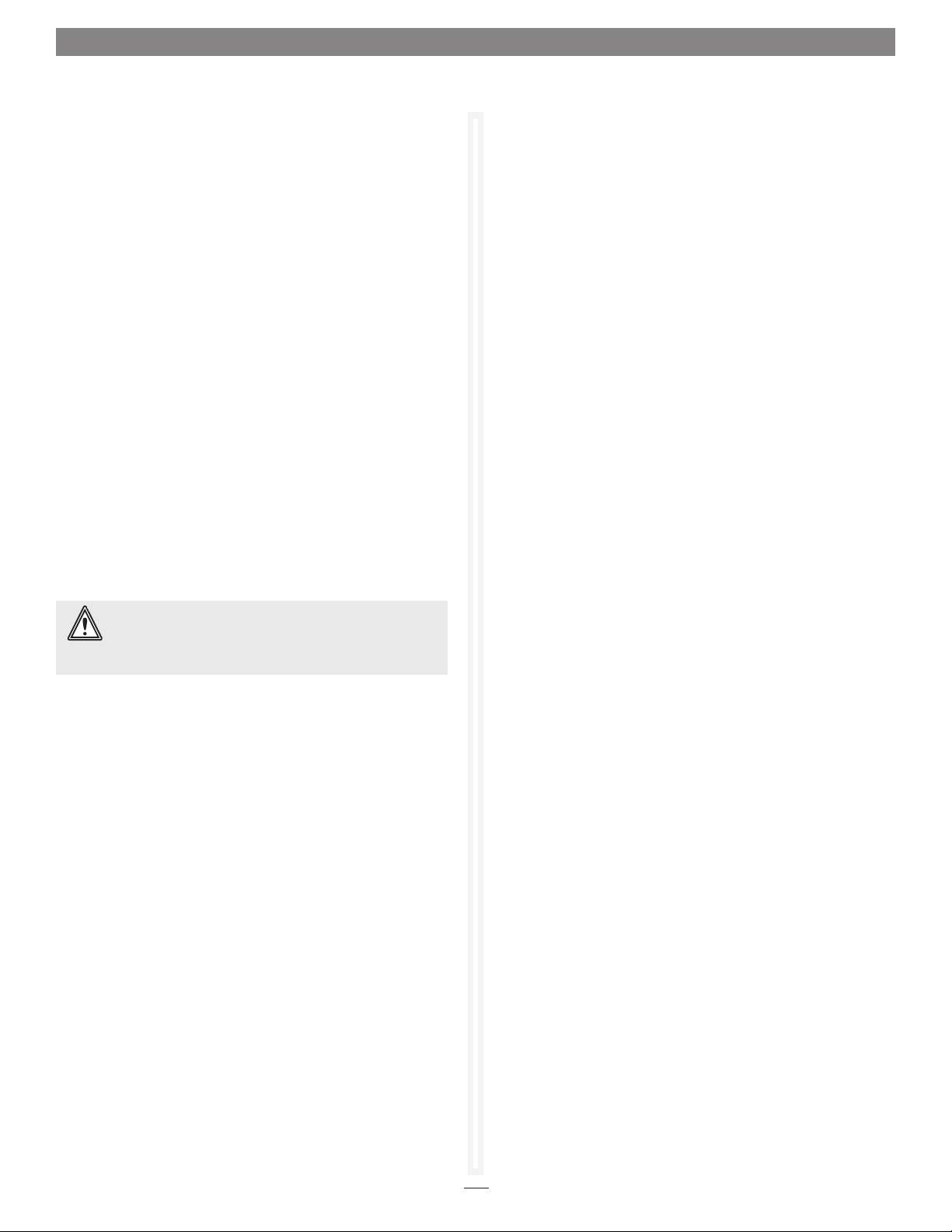
2. Select Initialize and Verify Drives.
3. Click Next.
4. Select Initialize and Verify Drives. All eligible drives are
highlighted in green; the system only initializes highlighted
drives. See Figure 3 on page 5.
5. Click Commit.
6. A warning box appears. In the warning box, verify that you
want to complete the configuration by clicking Yes. Clicking
No ends the procedure without making a change.
WARNING: Do not restart the RX1600Fibre or disconnect
or power cycle drives during drive initialization and
verification, or you must start the verification process from the
beginning.
7. When the process is complete, the Drive Performance
and Health page appears. The drive(s) selected are now
initialized and verified.
If you do not want to initialize or verify drives now, continue on
to Configure Storage Into RAID Groups on page 7.
Check drive integrity after you have created RAID groups on
drives which you wish to add to your FastStream configuration.
This can be accomplished by using the Initialize and Verify
Drives procedure or a read-only scan of drives.
The Read-Only Drive Test performs a nondestructive scan
over the entire surface of each drive to identify bad areas and
determine their read performance. It may be run while data is
passing through the FastStream. Running this test may negatively
impact performance.
Once the Read-Only Drive Test has completed, system operation
returns to normal.
All data on the highlighted drives has been erased and you may
continue with Configure Storage Into RAID Groups on page 7.
3
Page 10
1.1 Ensure Drive Integrity
After Creating RAID Groups
1. If you’re not already in the Sonnet Web Management Tool,
type the IP address of your RX1600Fibre in a standard
browser. On the splash screen, click Enter Here. In the box
provided, type in your user name and password, and then
click OK.
2. Click the Diagnostics button on the left side of the window.
3. Choose Initialize and Verify Drives to test newly added
drives that are not part of a RAID group. Choose Read-Only
Drive Test to nondestructively test any drives.
4. Click Next.
5. If no drives appear, click System Scan in the Drives box.
If drives are available, click the drives you wish to verify,
initialize or test; the drives are highlighted. See Figure 4 on
page 5.
6. Click Commit.
7. A warning box appears. In the warning box, verify that you
want to complete the configuration by clicking Yes. Clicking
No ends the procedure without making a change.
WARNING: Do not restart the RX1600Fibre or disconnect
or power cycle drives during Drive Initialization and
Verification or you must start the verification process from the
beginning.
8. The Drive Performance and Health page appears showing
what tests are running and their results. You may select
other tests to run or continue on to other tasks. See Figure 5
on page 6.
4
Page 11
1.1 Ensure Drive Integrity
Drives selected for initialization and verification when the Initialize and Verify Drives page is displayed
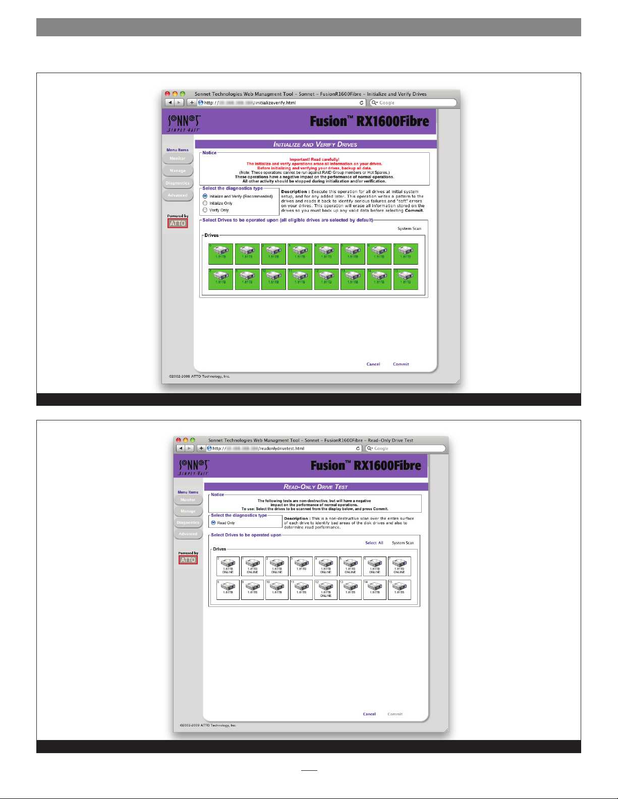
Read-Only Drive Test page before drives selected
Figure 3
Figure 4
5
Page 12
1.1 Ensure Drive Integrity
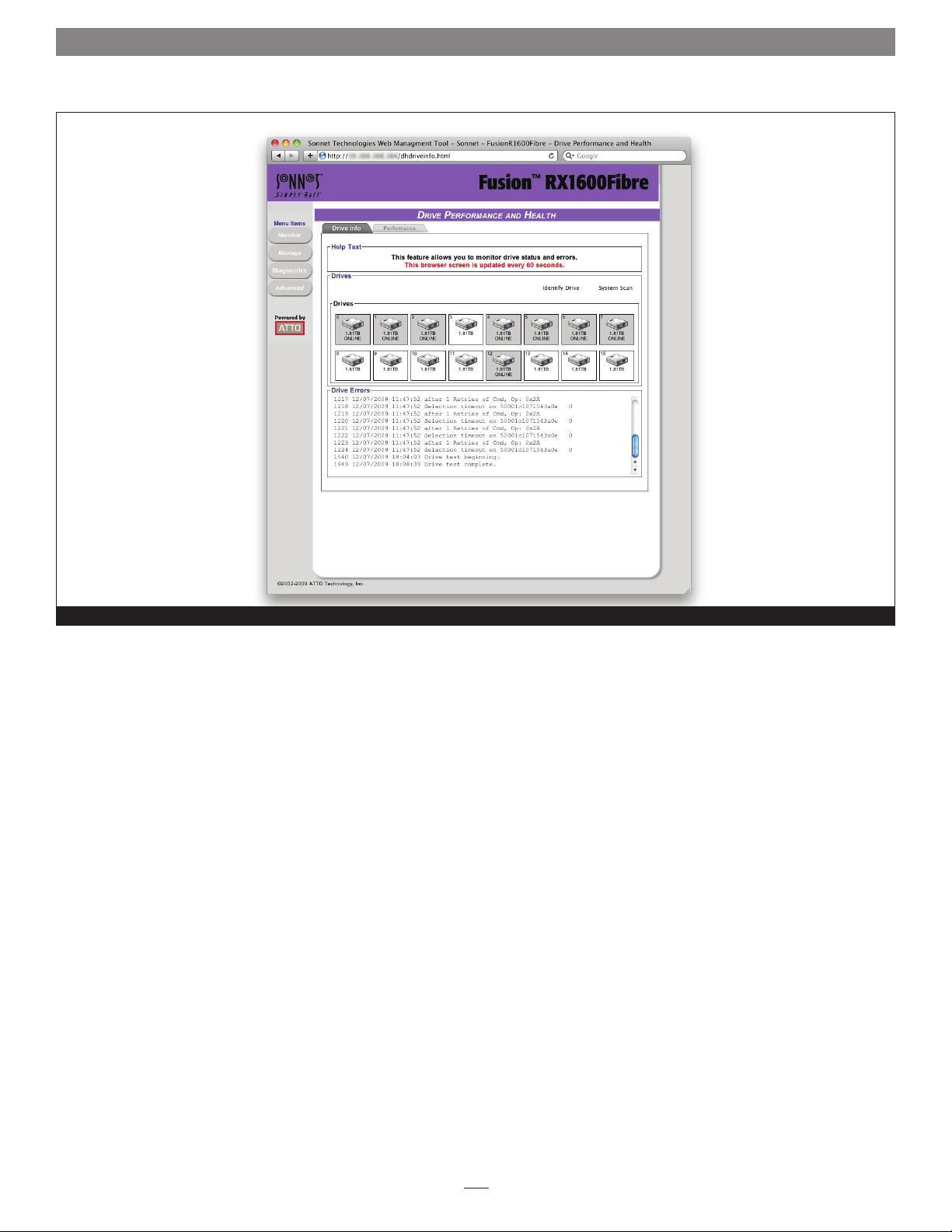
Drive Performance and Health Page Drive Info tab
Figure 5
6
Page 13
1.2 Configure Storage into RAID Groups
Support Note: In Fusion RX1600 systems shipped from
Sonnet with hard drives installed, the drives are formatted
Mac OS Extended (Journaled), configured as a single RAID 5 RAID
group, and ready for use with Mac OS X-based systems. If you
need to change the configuration, delete the existing RAID group
(see Deleting RAID Groups on page 31), and use the Sonnet Web
Management Tool and the operating system software tools to
reformat and reconfigure the drives. See Appendix D for Quick
Drive Reformat instructions for Mac OS and Windows users.
The Fusion RX1600Fibre enables configuration of storage into JBOD,
RAID Level 0, 1, 1+0, 4, 5, 6, or DVRAID RAID groups with the
ability to create multiple partitions.
RAID is a storage configuration which uses multiple drives to
increase capacity, performance, and/or reliability. The RX1600Fibre
can automatically set up an application-ready RAID configuration.
Also, you may custom design a RAID configuration, or combine
a custom and an automatic configuration. The RX1600Fibre uses
all available drives when you select Quick Digital Video, General
Digital Video, Audio, General IT, or Database. Available drives
include those which are on-line and not currently configured for
RAID or Hot Spares.
If you wish to have more than one type of RAID group in your
system, you have several options:
• Set up a customized RAID group (refer to Creating a Custom
Setup on page 9), then return to the main menu and select a
particular application to use the remainder of your attached
storage.
• Attach only the storage you want using an automated setup
(refer to Selecting a Quick Storage Configuration on page 8),
then attach more storage and use either the custom or specific
user processes outlined in this chapter.
• Set up storage now using any of the processes in this chapter,
then modify or add to storage using the procedures listed in
Modify Storage on page 31.
WARNING: Before creating any RAID group you should
initialize and verify the drives you want in the R AID group.
Refer to Ensure Drive Integrity on page 3.
Configuration of drives in protected RAID groups improves data
accessibility and reliability during normal operations. However,
you still need a good backup strategy for long-term protection
of data.
When you have created RAID groups, you may use, monitor
and modify the storage as needed. Refer to Monitor Storage,
Configurations on page 19, Modify System Values on page 17
Manage Sonnet Devices, Configurations on page 43, and Modify
Storage on page 31.
Features You May Choose
Depending on the application you choose, the number of drives
you choose and several other factors, you may have other choices
to customize your RX1600Fibre to your particular needs. Some
features are customized by you only if you use the custom setup.
Refer to Creating a Custom Setup on page 9.
Auto-Rebuild
When Auto-Rebuild is enabled and an existing RAID group
member becomes faulted, the RX1600Fibre’s controller initiates
a rebuild using an available unallocated drive. If no drives are
available, the rebuild is initiated only after you replace the faulted
drive and initiate a system scan to discover the drive. Hot Spares
will be used first, regardless of the Auto-Rebuild setting. Various
outcomes are available when Auto-Rebuild is enabled.
• If an existing RAID group member becomes faulted or
unavailable, such as when a drive is pulled out from an array, the
controller initiates a rebuild using an available unallocated drive.
• If the RX1600Fibre boots up with drives missing or faulted, it tries
to switch them out automatically.
• If no unallocated drive is available, you must replace the faulted
drive and a rebuild will begin. Hot Spares are not required,
allowing the maximum number of drives for data storage.
However, if you require maximum fault tolerance, it is best
practice to have a Hot Spare available to supply the unallocated
drive for immediate use. Refer to Adding or Removing Hot Spares
on page 34.
Fault Tolerance
Choose either Standard Fault Tolerance (no Hot Spare drives)
or Maximum Fault Tolerance (which adds Hot Spares to the
system) when creating parity RAID Groups. Refer to Adding or
Removing Hot Spares on page 34 for details.
Initialization
If you have not already initialized your drives as outlined in
Ensure Drive Integrity on page 3, you may choose to use the
Advanced Initialization for new drives to erase and verify drive
media and correct some soft drive errors. The RAID Group is
unavailable until the operation completes.
Choose Express Initialization to perform a quick background
initialization if you have already completed a full initialize and
verify operation. You may also choose Express Initialization to
change the configuration of drives in RX1600 storage systems
shipped from Sonnet with pre-installed drives. The RAID Group
being initialized is available for use during express initialization.
7
Page 14

1.2 Configure Storage into RAID Groups
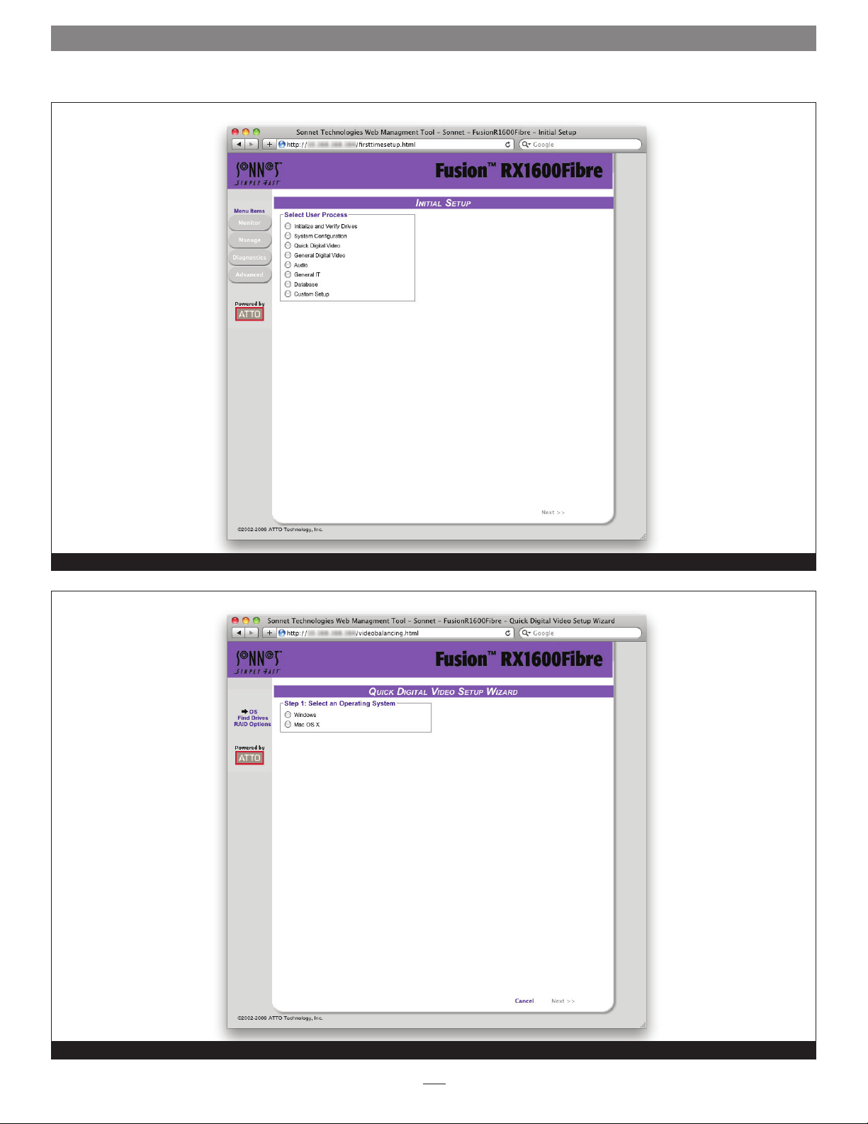
Selecting a Quick Storage Configuration
After initializing drives or setting up new storage, select an
application from the Initial Setup page or via the Manage page.
The Fusion RX1600Fibre finds all available drives and creates the
appropriate setup using those drives.
The most flexible choice is to use Custom Setup, but you must
understand your needs and your system well to use this option.
Refer to Appendix B - RAID Group Designs for more information
about RAID configurations.
Preliminary Steps
1. If you’re not already in the Sonnet Web Management Tool,
type the IP address of your RX1600Fibre in a standard
browser. On the splash screen, click Enter Here. In the box
provided, type in your user name and password, and then
click OK.
2. If you have not performed the steps detailed in Ensure Drive
Integrity on page 3 or created other RAID groups, the Initial
Setup menu appears. If you have initialized your storage or
created other RAID configurations,
a. From the selections at the left, select Manage.
b. Click RAID Groups inside the Select User Process box.
c. Click Create RAID Group.
d. Click Next.
3. Select one of the listed quick storage configurations, click
Next, and then continue using the directions in each
specific section. See Figure 6 on page 12.
• Quick Digital Video: provides parity RAID protection
(DVRAID) and optimized performance for digital video
(sequential access) configurations.
Note: DVRAID is only available using the Quick Digital Video setup
wizard.
• General Digital Video: provides parity RAID protection
for digital applications for configurations using three or
more drives.
• Audio: audio track streaming technology provides parity
RAID protection while managing latency to enable highspeed availability to support up to 192 tracks of 16-bit
audio or 96 tracks of 24-bit audio in a single editing
session. You must have only 4, 6, 8 or 12 drives available in
the system.
Quick Digital Video
1. After choosing Quick Digital Video, the Setup Wizard page
appears. See Figure 7 on page 12.
2. Select your operating system, click Yes, and then the system
restarts.
3. If all your drives do not appear in the Find Drives box, click
System Scan; this setup requires exactly 6, 12 or 24 drives
to appear as available on the screen after the scan. Physically
add or disconnect drives as needed and rescan.
4. Click Next.
5. Choose an Initialization method (refer to Initialization on
page 7).
6. Choose an Auto-Rebuild option (refer to Auto-Rebuild on
page 7).
7. Select a Fault Tolerance (refer to Fault Tolerance on page 7).
8. Click Commit.
9. A warning box appears. If you want to continue click Yes.
The configuration completes and the Health and Status
Monitor page appears. If you wish to start over, click No.
The Setup Wizard page appears.
10. Every RAID group must finish initializing, and be formatted
by your computer’s operating system software before it becomes
available for use; Mac users will use Disk Utility, Windows
users will use Disk Management. For more information on
drive formatting, see Mac OS Drive Formatting or Windows
Drive Formatting on page 11.
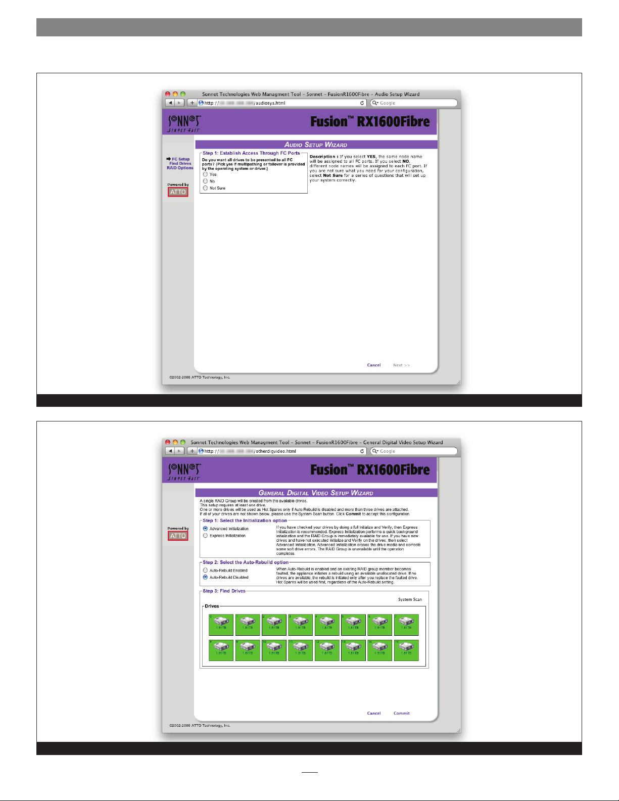
Audio
1. After choosing Audio, the Audio Setup Wizard page
appears. See Figure 8 on page 13. Choose to use the same or
a different node name for each host Fibre Channel port.
• If you know you want all drives to be available or
unavailable to all Fibre Channel ports, select Yes or No. If
you do not know, select Not Sure.
• If you select Not Sure, you will be asked a series of
questions to determine the correct configuration for your
needs and setup.
• General IT: provides parity RAID protection optimized for
random access applications using three or more drives.
• Database: provides parity RAID protection for database
applications (small transfer, random access) for
configurations using more than three drives.
• Several definitions are listed in a grey box at the bottom
of the Audio Setup Wizard screen which may help you
determine answers to the setup questions.
2. Click Next.
Note: Depending on your choice and your current system, the controller
may need to restart.
8
Page 15
1.2 Configure Storage into RAID Groups
Audio (continued)
3. If all your drives do not appear in the Find Drives box, click
System Scan. This setup requires 4, 6, 8 or 12 drives. Add or
disconnect drives as needed to ensure you have 4, 6, 8 or 12
drives appearing on the screen after the scan.
4. Click Next.
5. Choose an Initialization method (refer to Initialization on
page 7).
6. Choose an Auto-Rebuild option (refer to Auto-Rebuild on
page 7).
7. Select the number of users for this system.
8. Depending on the number of users and the number of
drives you have in your system, you may be asked choose a
Fault Tolerance (refer to Fault Tolerance on page 7).
9. Click Commit.
10. A warning box appears. If you want to continue click Yes.
The configuration completes and the Health and Status
Monitor page appears. If you wish to start over, click No.
The Setup Wizard page appears.
6. Every RAID group must finish initializing, and be formatted
by your computer’s operating system software before it becomes
available for use; Mac users will use Disk Utility, Windows
users will use Disk Management. For more information on
drive formatting, see Mac OS Drive Formatting or Windows
Drive Formatting on page 11.
Creating a Custom Setup
If the quick storage configurations do not suit your needs, you
may use Custom Setup to configure the FastStream.
1. After clicking Custom Setup, the RAID Setup Wizard page
appears. See Figure 10 on page 14. Click Next.
2. Decide if all drives are to be available to all ports; the choice
you make establishes the access for all RAID groups attached
to this FastStream.
• If you select Yes, the same node name is assigned to all
ports.
• If you select No, different node names are assigned to each
FC port.
3. Select a RAID level (refer to Appendix B - RAID Group
Designs). See Figure 11 on page 14.
11. Every RAID group must finish initializing, and be formatted
by your computer’s operating system software before it becomes
available for use; Mac users will use Disk Utility, Windows
users will use Disk Management. For more information on
drive formatting, see Mac OS Drive Formatting or Windows
Drive Formatting on page 11.
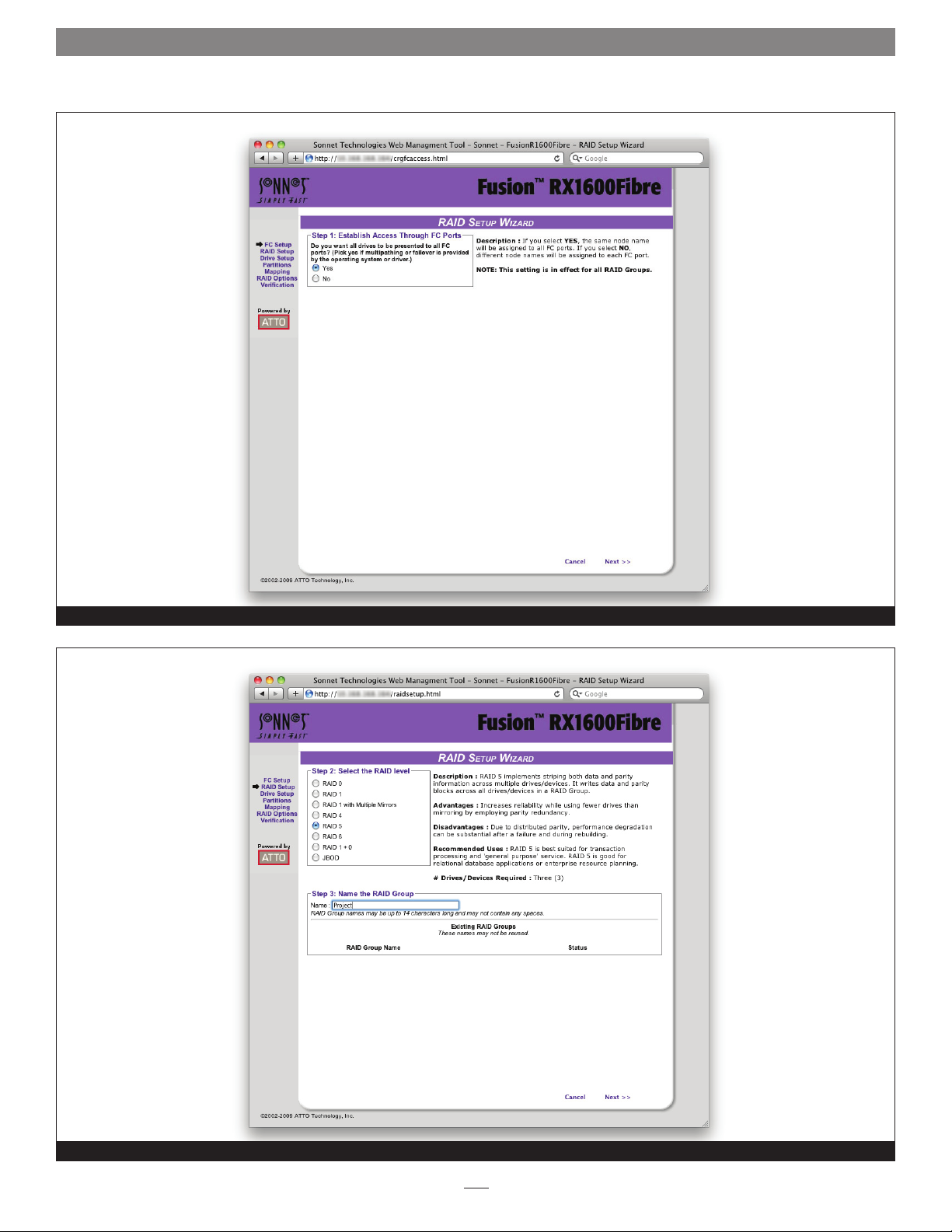
General Digital Video, General IT or Database
1. After choosing General Digital Video, General IT or
Database, the Setup Wizard page appears. See Figure 9
on page 13. Choose an Initialization method (refer to
Initialization on page 7).
2. Choose an Auto-Rebuild option (refer to Auto-Rebuild on
page 7).
3. If all your drives do not appear in the Find Drives box, click
System Scan.
4. Click Commit.
5. A warning box appears. If you want to continue click Yes.
The configuration completes and the Health and Status
Monitor page appears. If you wish to start over, click No.
The Setup Wizard page appears.
4. Type a unique name for your RAID group in the box
provided on the page under the Step 3 heading.
5. Click Next.
6. If your Fusion RX1600Fibre or attached Fusion RX1600
Expansion has drives associated with it, choose a method for
selecting drives from the following:
a. Use all drives in an enclosure for your RAID Group.
Support Note: Due to the configuration its components,
a Fusion RX1600Fibre enclosure’s drives will be displayed as
being spread across two enclosures (eight in each). When you
intend to use all 16 drives in a RAID group, be sure to select
drives from both “enclosures”, other wise only eight drives will be
selected.
b. Use all drives in an enclosure for your RAID Group plus
one for a Dedicated Hot Spare.
c. Select your own drives.
7. If necessary, click System Scan to discover the drives
available for RAID configuration.
8. When the scanned drives box is populated, click the boxes
representing the drives for the RAID group named in Step 4.
See Figure 12 on page 15.
9
Page 16
1.2 Configure Storage into RAID Groups
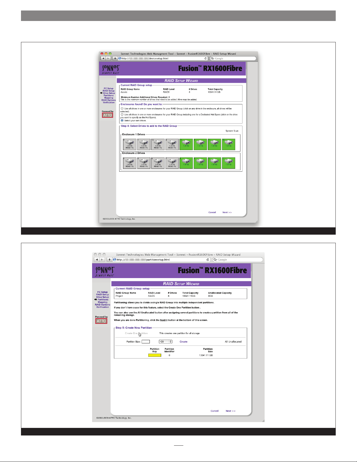
Creating a Custom Setup (continued)
9. Click Next.
10. Choose the number of partitions for the RAID group. See
Figure 13 on page 15.
• A RAID group may have several Terabytes of total data
capacity because of the size of the included drives.
Partitions allow you to break up large RAID groups into
smaller, more manageable groups.
• Most host systems can address only 2TB per LUN.
Partitioning increases storage efficiency by providing more
LUNs without using lower capacity RAID groups.
• Partitioning allows the creation of multiple logical
volumes.
Note: If you don't want to use partitions, click the All Unallocated
button.
a. Click Create One Partition, or enter the desired partition
size for the first partition from the available RAID group
capacity.
b. Click Create.
c. If you have created more than one partition, repeat entering
the partition size and clicking Create as often as you need
to partition the remaining capacity. Whenever you have
completed designating partitions, click All Unallocated to
put all the remaining capacity into one partition.
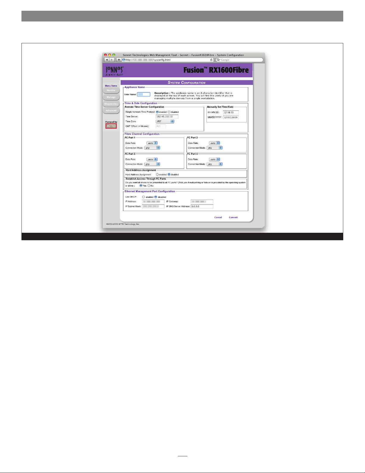
14. Choose the Interleave by clicking the drop-down box and
selecting a value. See Figure 15 on page 16.
Support Note: The interleave value chosen when
creating a RAID group makes a significant impact on
performance. Fusion RAID storage systems shipped from Sonnet
with pre-installed hard disk drives are now optimized for use
with video editing (larger files) applications, typically with an
interleave value of 512KB or 1MB selected. If you intend to
use your storage system primarily for storage of smaller files
(database, office documents, etc.), choose a smaller interleave
value of 64KB or 128KB.
15. Select a Sector Size. The RAID group sector size must be
evenly divisible by the sector size of any member disk.
• 512 bytes is the default size for most operating systems.
• For Windows XP (32-bit support) select 4KB sectors
to enable large volume support (greater than 2TB, up to
16TB).
16. Select a SpeedRead feature. SpeedRead looks ahead during
reads and stores the data in cache memory. The optimum
setting depends on your actual I/O and storage. You may
adjust this setting later.
• Enabling SpeedRead may boost performance when you
are running video playback and other applications which
access data sequentially.
• Disabling SpeedRead is a better choice for audio
applications.
11. Click Next. The storage capacity is allocated.
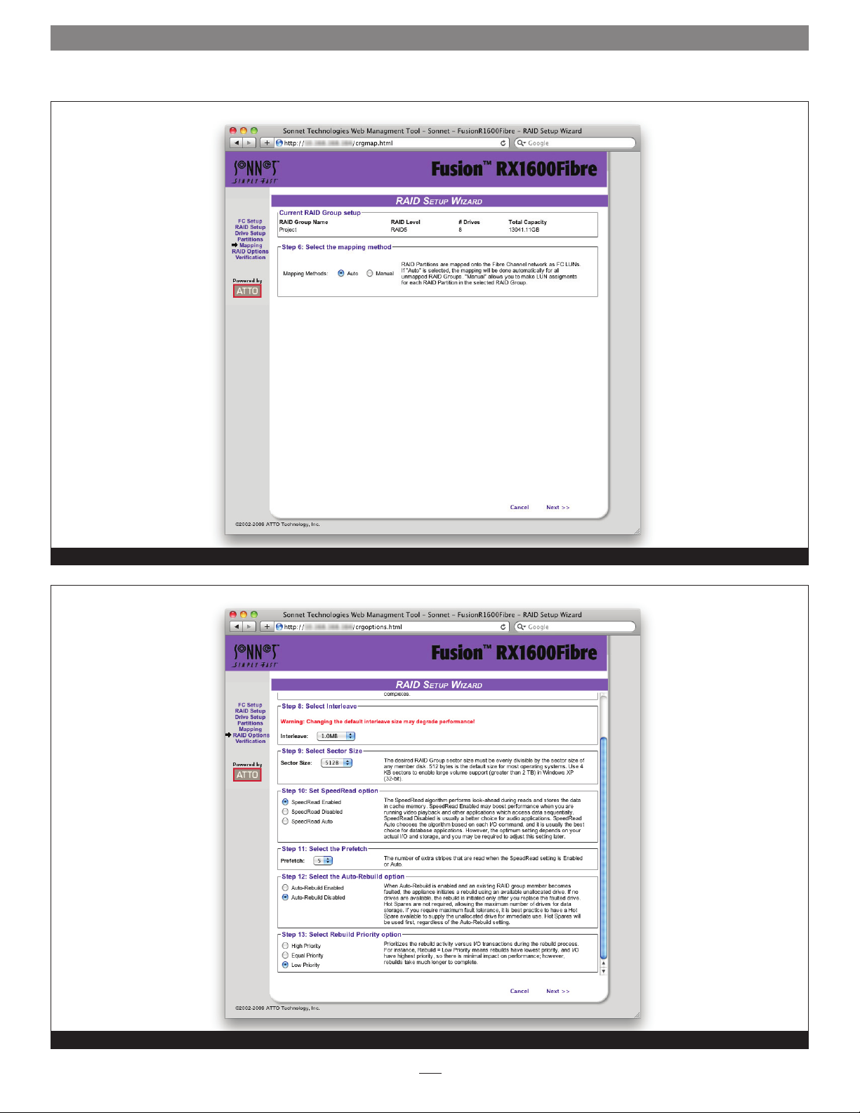
12. RAID partitions are mapped onto the Fibre Channel network
as FC LUNs (SCSI-FCP LUNs). Select the method you wish to
use to map the partitions. See Figure 14 on page 16.
• If you select Auto, all mapping for all RAID groups
attached to the RX1600Fibre is changed, destroying any
previous mapping.
• If you do not wish to change the mapping of your other
RAID groups, select Manual. Manual mapping allows you
to make LUN assignments for each RAID partition in the
selected RAID group.
a. From the RAID Configuration page presented, under
Select the mapping method, click the Manual radio
button.
b. Click any partition to map that partition to a Port and
LUN.
13. Choose an Initialization method (refer to Initialization on
page 7).
• SpeedRead Auto is usually the best choice for database
applications.
17. Choose a Prefetch option. The number of extra stripes that
are read when the SpeedRead setting is set to enabled or
auto.
18. Choose an Auto-Rebuild feature if it is available for your
RAID configuration (refer to Auto-Rebuild on page 7).
19. Choose a Rebuild Priority level. Rebuild Priority allows
you to determine whether rebuild or I/O transactions take
precedence during rebuild operations. If you choose low
priority, for example, rebuilds take longer but the rebuild has
minimal impact on performance.
Support Note: Rebuild priority affects the performance
of your Fusion storage system when a drive is replaced and
a degraded RAID group is rebuilt. Selecting Low rebuild priority
enables you to continue working at the best performance level
possible, but the RAID group will take much longer to rebuild.
10
Page 17

1.2 Configure Storage into RAID Groups
20. Click Next.
21. A chart showing the setup you have selected appears. If
everything is the way you want it, click Commit to save
your configuration.
22. For RAID types that rebuild, a warning box tells you that
all data on the attached disks is to be destroyed during the
rebuild process. In the warning box, verify that you want
to complete the configuration by clicking Yes. Clicking No
ends the procedure without making a change.
23. The RX1600Fibre configures the storage (the process will
likely take several hours). Upon clicking Yes, the Health and
Status Monitor page appears.
24. Every RAID group must finish initializing, and be formatted
by your computer’s operating system software before it becomes
available for use; Mac users will use Disk Utility, Windows
users will use Disk Management. For more information on
drive formatting, see Mac OS Drive Formatting or Windows
Drive Formatting below.
Mac OS Drive Formatting
1. Depending on how you configure your setup, a Disk Insertion
window stating that there is an unreadable volume will
appear at some point during the RAID group creation process;
click Initialize, and then Disk Utility will open.
2. In the Disk Utility window, each RAID group you created
using the ATTO Configuration Tool will appear as a single
volume. Select the volume, and then click the Erase tab at the
top of the window.
Support Note for Power Mac G5 Users: When
creating RAID groups 16TB or larger, uncheck the Install
Mac OS 9 Drivers checkbox; OS 9 drivers do not support volumes
greater than 16TB.
Windows Drive Formatting
1. Select Start > Control Panel > Administrative Tools from the
Windows Start menu. In the Administrative Tools window,
double-click Computer Management.
2. In the Computer Management window, click Storage on the
left, and then double-click Disk Management.
3. When the Initialize Disk window appears, click OK.
4. In the Disk Management window, each RAID group you
created will appear (listed as “unallocated”) as a single volume.
Right-click where the word “unallocated” appears, and then
select New Simple Volume.
5. When the Welcome to the New Simple Volume Wizard window
appears, click next to start the process.
6. Follow the remaining steps to complete the process.
Note: If you do not select the quick format option, formatting will take
much longer to complete.
7. Repeat steps 4–6 for each remaining “unallocated” disk.
8. Depending on how you configured the RAID groups, the
volumes may already be mounted and present on the desktop.
If you created a DVRAID, RAID 4, RAID 5, or RAID 6 RAID
group, configuration will take much longer. You may check
on the process by clicking the Monitor button to the left of
the window.
9. Once all the RAID groups have been formatted and finish
building, they are ready to use.
3. Click the Erase button; a window will appear asking you to
approve your choice; click Erase.
4. Repeat steps 2 and 3 for each remaining unformatted RAID
group, and then close Disk Utility.
5. Depending on how you configured the RAID groups, the
volumes may already be mounted and present on the desktop.
If you created a DVRAID, RAID 4, RAID 5, or RAID 6 RAID
group, configuration will take much longer. You may check
on the process by clicking the Monitor button to the left of
the window.
6. Once all the RAID groups have been formatted and finish
building, they are ready to use.
11
Page 18
1.2 Configure Storage into RAID Groups
Initial Setup page before a storage configuration has been selected
Quick Digital Video Setup Wizard start page
Figure 6
Figure 7
12
Page 19
1.2 Configure Storage into RAID Groups
Audio Setup Wizard start page
Figure 8
General Digital Video Setup Wizard start page with all drives selected for RAID group
Figure 9
13
Page 20
1.2 Configure Storage into RAID Groups
Custom RAID Setup Wizard start page
Figure 10
Selecting the RAID level and RAID group name using the custom RAID Setup Wizard
Figure 11
14
Page 21
1.2 Configure Storage into RAID Groups
Creating a RAID group comprised of eight drives using the custom RAID Setup Wizard
Figure 12
Creating a RAID 5 RAID group comprised of a single partition using the custom RAID Setup Wizard
Figure 13
15
Page 22
1.2 Configure Storage into RAID Groups
Selecting automatic SCSI-FCP LUN mapping for RAID partitions using the custom RAID Setup Wizard
Figure 14
Selecting the RAID group options using the custom RAID Setup Wizard
Figure 15
16
Page 23

1.3 Modify System Values
Default values are appropriate for most configurations, but may be
modified for your needs using the Sonnet Web Management Tool.
It is best practice to change the default user name and
password to a user name and password important to you.
Other configurations may also be changed; however, use extreme
caution when changing default values.
Changing the Current User Name, Password
It is best practice to change the user name and password on all
Telnet, FTP and Sonnet Web Management Tool sessions. Refer to
the CLI commands UserName and Password in Appendix A.
1. Open a Command Line Interface session either using
Telnet or the serial port as described in Interface Options
on page 47, or use the Advanced CLI page in a Sonnet Web
Management Tool session as described in Advanced CLI Page
on page 35.
2. Type set UserName [name].
3. Press Return (Enter).
4. Type set Password.
5. Press Return (Enter).
6. Follow the onscreen instructions to confirm your old and
new passwords.
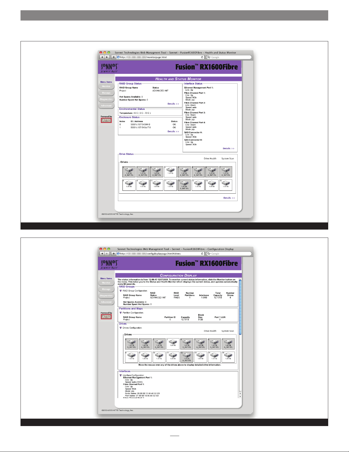
Changing System Variables - System Configuration
You may change several system configurations to suit your needs.
1. If you are not already in the Sonnet Web Management
Tool, type the IP address of your RX1600Fibre in a standard
browser, click Enter Here on the splash screen, then type
in your user name and password in the box provided. Click
OK.
2. Click the Manage button on the left side of the window.
3. Click Fusion RX1600Fibre inside the Select User Process box.
4. Click System Configuration.
5. Click Next. The System Configuration page appears. See
Figure 16 on page 18.
6. Make any changes:
• Appliance name: the appliance name is a unique
8-character identifier which is displayed at the top of each
screen. You may find this useful if you are managing
multiple ATTO controller-based devices from a single
workstation.
• Time and date: use a remote time server to set the time
and time zone, or manually set the time and date. Refer to
Date, Time, TimeZone in Appendix A.
Note: The user name is case insensitive and password is case sensitive.
The user name and password for all Telnet, FTP and Sonnet
Web Management Tool sessions is changed.
Creating a Read-Only User Name, Password
You may wish to set up a read-only user name and password to
prevent changes to storage and Sonnet Web Management Tool
settings. Refer to the CLI commands ReadOnlyPassword and
ReadOnlyUsername in Appendix A.
1. Open a Command Line Interface session either using Telnet
or the serial port as shown in Interface Options on page 47.
2. Type set ReadOnlyUsername [name].
3. Press Return (Enter).
4. Type set ReadOnlyPassword.
5. Press Return (Enter).
6. Follow the onscreen instructions to confirm the read-only
password; the read-only user name and read-only password
for all user interface sessions is changed.
• Fibre Channel configuration: change the data rate or the
connection mode for each FC port. Refer to FCDataRate
and FCConnMode in Appendix A.
• Hard address assignment: refer to FCHard and
FCHardAddress in Appendix A.
• Establish access through FC Ports: change whether all
drives are to be available to both ports, creating one node
name for all ports, or if different node names should be
created for each port.
• Ethernet management port: change whether or not you
use DHCP for an IP address, subnet mask and gateway, or
manually change these parameters and set a DNS server
address. Refer to IPDHCP in Appendix A.
7. When you have completed your changes, click Commit.
17
Page 24
1.3 Modify System Values
System Configuration page
Figure 16
18
Page 25

1.4 Monitor Storage, Configurations
You may determine the performance of drives in the Fusion
RX1600Fibre or attached RX1600 Expansion systems using various
displays and tests in the Sonnet Web Management Tool.
The following instructions assume you have already set up at
least one RAID group. The ATTO FastStream controller in the
RX1600Fibre collects various metrics to measure performance
for physical drives during normal system operation and drive
initialization and verification.
Note: New performance data is updated every 60 seconds which
impacts performance slightly, even if you minimize the browser
window. Exit the Sonnet Web Management Tool completely
whenever you need maximum performance.
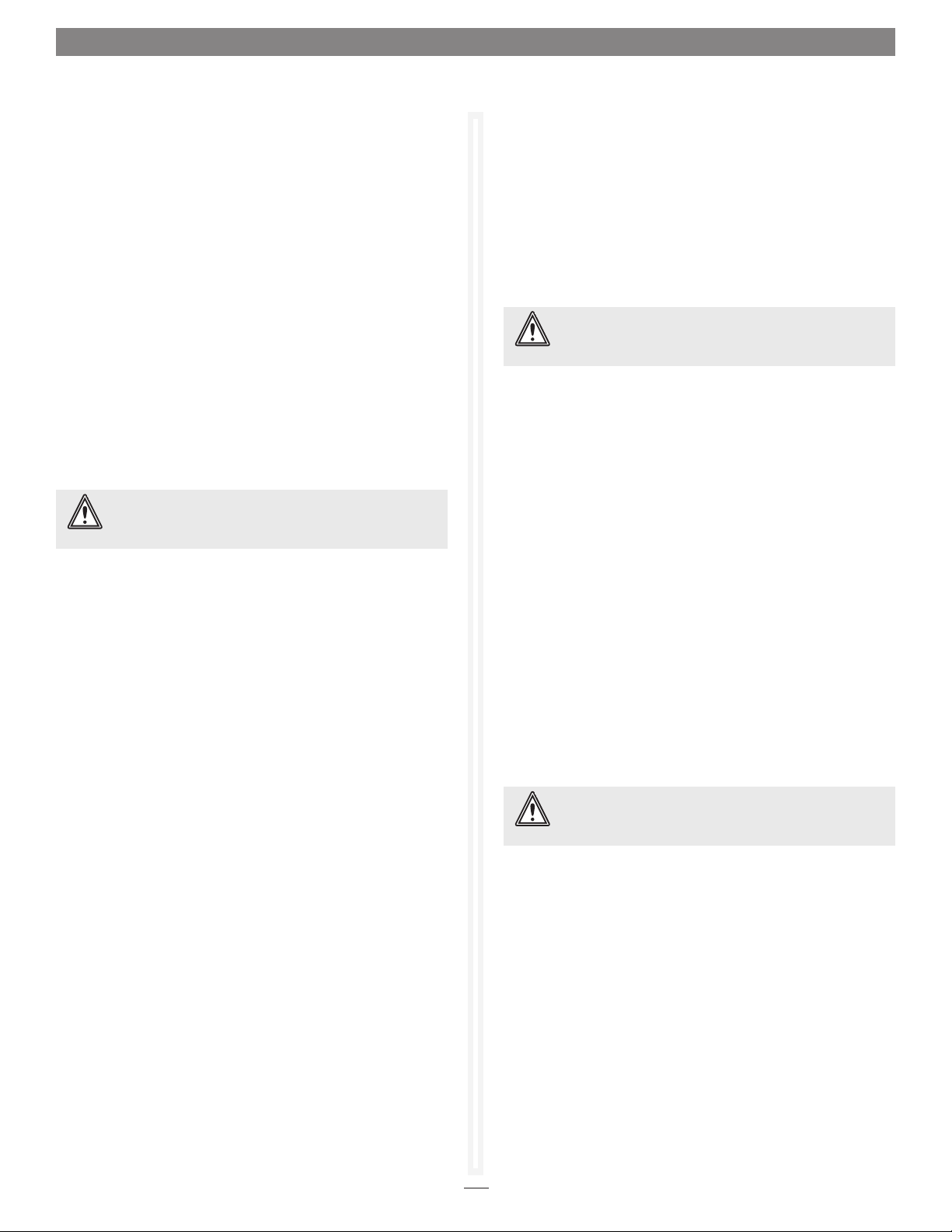
Health and Status Monitor Page
The Health and Status Monitor page is the first page you
see when you open the Sonnet Web Management Tool after
completing the configuration of at least one RAID group. You
may return to it at any time by clicking the Monitor button on
the left side of the window. See Figure 17 on page 20.
1. If you’re not already in the Sonnet Web Management Tool,
type the IP address of your RX1600Fibre in a standard
browser. On the splash screen, click Enter Here. In the box
provided, type in your user name and password, and then
click OK.
SCSI Enclosure Services (SES)
Fusion RX1600Fibre and Fusion RX1600 expansion enclosures
feature a SCSI Enclosure Processor which indicates enclosure health
status, drive identification and drive fault identification.
Use SES to identify individual drives, all the drives in the same
enclosure, all the drives in a single RAID group, or faulted drives.
Clicking Details in the Enclosure Status section on the Health
and Status Monitor page brings up the SES Monitor page. Refer to
SCSI Enclosure Services (SES) on page 27.
2. The Health and Status Monitor page appears. If you click
Details, additional information about each parameter appears
on the Configuration Display page.
Configuration Display Page
Clicking Details from the Health and Status Monitor page brings
up the Configuration Display page. See Figure 18 on page 20.
Click the following links to view detailed information:
• RAID groups: RAID group names, RAID status, available
Hot Spares, number of faulted drives, RAID level, number of
partitions, interleave and total capacity of each RAID group
• Partitions: RAID group name, partition ID, capacity and block
size
• Drives: Drive configuration by port, including drive size and
status
• Interfaces: Ethernet management port link status and Fibre
Channel port link, speed, connection mode, node name and
port name
19
Page 26
1.4 Monitor Storage, Configurations
The Health and Status Monitor page during a RAID group initialization operation
Figure 17
Fusion RX1600Fibre configuration and status information displayed on the Configuration Display page
Figure 18
20
Page 27

1.5 Remote System Monitoring
You may set up the Fusion RX1600Fibre to send notifications using
Email when certain events occur.
You may set up the RX1600Fibre to send notifications using
the Sonnet Web Management Tool’s Error Notifcation page
when certain events occur. You designate the person or people
receiving notification of conditions and the level of severity
which prompt Email notification.
Types of Errors
• Device/drive errors such as medium error, aborted command
and hard error
• Device/drive transitions from online to offline
• Critical and warning temperature conditions
• Critical and warning voltage conditions
• Power recycle/power failure conditions
• Enclosure issues
Warning messages
• Device down
• Medium error
When an event occurs that warrants Email notification, the
RX1600Fibre sends the message; it cannot respond to a rejection by a
server for an invalid address. Ensure all Email addresses typed in
are valid. Each Email is time stamped when it is sent as part of
the SMTP header information.
1. If you’re not already in the Sonnet Web Management Tool,
type the IP address of your RX1600Fibre in a standard
browser. On the splash screen, click Enter Here. In the box
provided, type in your user name and password, and then
click OK.
2. The Health and Status Monitor page appears. Click the
Manage button on the left side of the window.
3. The Manage menu page appears. Click Fusion RX1600Fibre.
4. Click the Set Up Error Notification button.
5. Click Next. The Error Notification page appears. See
Figure 19 on page 22.
6. Click the Enabled radio button for Notification
Configuration.
7. Type in the sender address or use the default. (Emails show
this name in the From field).
• Abort command
Message Severity Levels
• Critical: critical event Emails
• Warning: warnings and critical event Emails are sent
• Informational: information which you may want to know
but which probably does not require action: only information
messages are sent
• All: warnings, critical events and informational messages
• None: no Emails are sent
Email Notification Setup
Phone home Email notification enables the RX1600Fibre to send
an Email message to you, a network administrator or other users
when certain events occur with the storage system.
Messages about serious errors are sent immediately, while
messages for less serious errors are sent every 15 minutes. You
may send messages to up to five Email addresses and designate
which conditions prompt each Email notification. For example, a
recipient set to receive only critical severity level messages receives
critical messages and not warning or informational messages.
8. Type or use the default SMTP Server (the Email server) IP
address or the name of the SMTP server and, if required, the
user name and password used to log into the server.
9. Type in up to five Email addresses.
10. Choose All, Critical, Warning, Informational or None for
each Email address.
11. When all information is typed in, click Commit.
12. A warning box appears. In the warning box, verify that you
want to complete the notification procedure including a
restart of the RX1600Fibre by clicking Yes. Clicking No ends
the procedure without making a change.
13. Your settings are displayed. You may change or disable Email
notification at any time from the Error Notification page.
21
Page 28

1.5 Remote System Monitoring
Error Notification setup page
Figure 19
22
Page 29

1.6 Drive Diagnostics
You may determine the performance of drives in the Fusion RX1600Fibre
and attached RX1600 Expansion systems using various displays and
tests in Sonnet Web Management Tool.
The following instructions assume you have already set up at
least one RAID group. The RX1600Fibre collects various metrics
to measure performance for physical drives during normal
system operation and drive initialization and verification. New
performance data is updated every 60 seconds, which impacts
performance slightly, even if you minimize the browser window.
Exit the ExpressNAV Storage Manager completely whenever
you need maximum performance.
Note: Initialize and Verify Drives is Described in Section x.x, Ensure
Drive Integrity on page 3.
Preliminary Steps
1. If you’re not already in the Sonnet Web Management Tool,
type the IP address of your RX1600Fibre in a standard
browser. On the splash screen, click Enter Here. In the box
provided, type in your user name and password, and then
click OK.
2. The Health and Status Monitor page appears.
3. Click the Diagnostics button on the left. The Diagnostics
Menu page appears. See Figure 20 on page 25.
4. Select the operation you wish to perform.
Read-Only Drive Test
The Read-Only Drive Test performs a nondestructive scan over
the entire surface of each drive to identify bad areas of the disk
drives and determine read performance. It may be run while data
is passing through the RX1600Fibre.
6. A warning box appears. In the warning box, verify that
you want to complete the configuration by clicking Yes.
Clicking No ends the procedure without making a change.
If you chose to do a Read-Only Drive Test, the Drive
Performance and Health page appears showing what tests
are running and their results. You may select other tests to
run or continue on to other tasks.
Drive Performance and Health Test
Another way to determine your drives’ status is to follow the
instructions in Preliminary Steps on this page, and click the
Drive Performance and Health menu item.
1. Follow the instructions in Preliminary Steps on this page.
2. Click the Drive Performance and Health menu item.
3. The Drive Performance and Health page appears. See
Figure 22 on page 26.
4. Click the Start or Stop buttons next to individual drives
to start or stop drive performance and health testing.
Alternatively, you may click Start All Metrics to test all the
drives.
• Click Show Help Text and Drives for an alternative view
of the test progress.
• During testing the Time Remaining box tells you how
much time remains until the verification process is
complete. The representation of each drive in the Drives
box shows the percentage of verification completed.
• Drive performance is displayed in the Drive Metrics section.
Running this test may negatively impact performance. Once the
Read-Only Drive Test has completed, system operation returns
to normal. To fix errors on disks, use the Initialize and Verify
Drives process as described in Ensure Drive Integrity on page 3.
1. Follow the instructions in Preliminary steps above.
2. Click the Read-Only Drive Test button.
3. Click Next. The Read-Only Drive Test page appears. See
Figure 21 on page 25.
4. If no drives appear in the information box, click the System
Scan button. If drives are available, click the drives you wish
to test; the drives are highlighted.
5. Click Commit.
• Drive errors are displayed in the Drive Errors section.
5. When the test is complete, click each drive to see its
information highlighted in the Drive Metrics window.
If you close the browser or navigate away from this page,
you may re-access these results by clicking the Diagnostics
button and choosing the Drive Performance and Health
option. Results are available until the FastStream is restarted.
23
Page 30

1.6 Drive Diagnostics
Identifying a Drive
WARNING: Executing this command adversely impacts
performance and throughput for the time that the LED
is illuminated. The preferred method to identify SES elements as
described in Identifying SES Elements on page 27.
You may want to physically identify a drive in the RX1600Fibre
or attached RX1600 Expansion systems. This method will work
even if SES is unavailable.
1. Follow the instructions in Preliminary Steps on page 23.
2. Click Identify Drive. The Identify SES Elements page
appears. See Figure 23 on page 26.
3. Click the box representing the drive you wish to identify.
Alternatively, you may click Identify All to select all the
drives.
4. Click Commit. The drive activity LED(s) for the drive(s) in
the Fusion drive enclosure illuminates for one minute.
5. To stop the operation, deselect the drive(s).
24
Page 31

1.6 Drive Diagnostics
Diagnostics Menu page
Drives selected for testing on the Read-Only Drive Test page
Figure 20
Figure 21
25
Page 32

1.6 Drive Diagnostics
Drive Performance and Health page while a RAID group is tested
Figure 22
Identify enclosure, RAID group and drives, enclosure, RAID group, or individual drives using the Identify SES Elements page
Figure 23
26
Page 33

1.7 SCSI Enclosure Services (SES)
Fusion RX1600 drive enclosures have a SCSI Enclosure Processor which
monitors enclosure health status, drive identification and drive faults.
You may use SES to identify individual drives, all the drives in
the same enclosure, all the drives in a single RAID group, or
faulted drives. SES also provides status on power supplies, fans
and thermal sensors in the enclosures.
Setting up SES
1. If you’re not already in the Sonnet Web Management Tool,
type the IP address of your RX1600Fibre in a standard browser.
On the splash screen, click Enter Here. In the box provided,
type in your user name and password, and then click OK.
2. The Health and Status Monitor page appears. Click the
Manage button on the left side of the window.
3. Select Enclosure Services in the Select User Process box.
4. Select Manage Enclosure Services.
5. Click Next. The Manager Enclosure Services page appears.
See Figure 24 on page 28.
6. Select the type of SES monitor and control you wish to use:
• Pass-Through: the host application manages SES
information.
Identifying SES Elements
The SES Monitor page found by clicking Details in the
Enclosure Status section of the Health and Status Monitor page
shows the RX1600Fibre and any attached RX1600 Expansion
systems’ SES information. If you would like information about
specific drives of the RAID groups or enclosures of which they are
members, use the Identify SES Elements page.
1. If you’re not already in the Sonnet Web Management Tool,
type the IP address of your RX1600Fibre in a standard
browser. On the splash screen, click Enter Here. In the box
provided, type in your user name and password, and then
click OK.
2. The Health and Status Monitor page appears. Click the
Diagnostics button on the left side of the window.
3. Click Identify Drives.
4. Click Next. The Identify SES Elements page appears. See
Figure 25 on page 28.
5. Move the cursor over any drive to display its information.
6. After choosing a drive, click its button, and then click Drive,
RAID Group, Enclosure, or Identify All to identify enclosures
or RAID groups associated with that drive. LEDs for the
devices light up when selected.
• Monitor and Control by the Fusion RX1600Fibre: the
RX1600 controls SES services.
• SES Monitoring Disabled: the host application does not
receive any SES monitoring information.
7. If you enable enclosure services, select the amount of time
in seconds that SES enclosures are asked (or polled) for their
current status. The default is 60 seconds: you may choose an
interval up to 60 minutes.
8. If you have elected to enable enclosure services, and you
want the enclosure to sound an alarm if a drive becomes
faulted, select the Enable Faulted Drive Alarm box.
9. Choose to test an enclosure’s alarm or to mute alarms. You
may also choose to have an occasional audible reminder of
the alarm condition if it is supported by your enclosure.
10. If Email Notification is enabled (see Email Notification Setup
on page 21), all SES status changes are sent via email.
7. Select Stop All to stop the LEDs from lighting.
Monitoring SES Elements Using the Health and
Status Monitor
1. If you’re not already in the Sonnet Web Management Tool,
type the IP address of your RX1600Fibre in a standard
browser. On the splash screen, click Enter Here. In the box
provided, type in your user name and password, and then
click OK.
2. The Health and Status Monitor page appears. In the
Enclosure Status section, click Details.
3. The Monitor Enclosure Services page appears. See Figure
26 on page 29.
27
Page 34

1.7 SCSI Enclosure Services (SES)
Set SES monitor and control on the Manage Enclosure Services page
Figure 24
Identify enclosure, RAID group and drives, enclosure, RAID group, or individual drives using the Identify SES Elements page
Figure 25
28
Page 35

1.7 SCSI Enclosure Services (SES)
Expanded view of an enclosure’s SES elements in the Monitor Enclosure Services page
Figure 26
29
Page 36

30
Page 37

1.8 Modify Storage
Use the Sonnet Web Management Tool to replace a failed drive, add
new drives or change RAID configurations.
You may modify various aspects of storage using the Manage
menu found by clicking the Manage button on the left side of the
window. Be cautious when deleting storage or rearranging storage
configurations because data could be compromised or lost.
The Sonnet Web Management Tool takes you step by step
through many procedures which allow you to modify your
storage and RAID configurations. Read all notes and warnings
carefully as you go to ensure the best performance and use of
your storage. When you initially set up the Fusion RX1600Fibre,
replace a failed drive or add new drives to the system, perform
drive initialization and verification. Refer to Ensure Drive
Integrity on page 3.
Many of these procedures are only available on unallocated
storage which is not currently part of a RAID group, not
designated as a Hot Spare (refer to Adding or Removing Hot
Spares on page 34), or has been designated as “Replaced” when
you initially set up RAID configurations.
Preliminary Steps
Begin with these steps, then choose the process you wish to use.
1. If you’re not already in the Sonnet Web Management Tool,
type the IP address of your RX1600Fibre in a standard
browser. On the splash screen, click Enter Here. In the box
provided, type in your user name and password, and then
click OK.
2. The Health and Status Monitor page appears.
3. Click the Manage button on the left side of the window.
4. The Manage menu page appears. From the Select User
Process box, select the operation you wish to perform.
RAID Group Processes
You may create or delete RAID groups, change RAID group
levels, rebuild RAID groups or modify RAID group mapping or
partitions.
Creating RAID Groups
1. Follow the instructions in Preliminary Steps above, and then
click the RAID Groups arrow in the Select User Process box.
2. Click Create RAID Group.
Deleting RAID Groups
1. Follow the instructions in Preliminary Steps on this page,
and then click the RAID Groups arrow from the Select User
Process box.
2. Click Delete RAID Groups.
3. Click Next. The Delete RAID Groups page appears. See
Figure 27 on page 36.
4. If you want to delete Hot Spares, click the appropriate radio
button. (Refer to Adding or Removing Hot Spares on page
34.)
5. Click each RAID group to be deleted.
6. Click the Delete button.
7. When you have selected all the groups to be deleted, click
Commit.
8. A warning box appears. If you want to continue click Yes.
The configuration completes and the Health and Status
Monitor page appears. If you wish to start over, click No.
Adding Drives to a RAID Group
Mac User’s Support Note: Although this feature is
supported by the ATTO utility, as of this writing, Mac
OS X does not support RAID group capacity expansion.
You can increase the number of drives used by an existing RAID
group by adding an unallocated drive to the group. The new
drive is set up in a separate partition within the RAID group. You
may have to add more than one drive depending on the RAID
group setup.
WARNING: Adding drives to an existing RAID group may
adversely impact per formance. You cannot reverse this
operation unless you delete the RAID group.
1. Follow the instructions in Preliminary Steps on this page
and click the RAID Groups arrow from the Select User
Process box.
2. Click Add Drives to a RAID Group.
3. Click Next. The Add Drives to RAID Group page appears.
See Figure 28 on page 36.
3. Follow the directions as found in Selecting a Quick Storage
Configuration on page 8 or Creating a Custom Setup on
page 9.
4. Select the RAID group you wish to add the drives to from
the drop-down menu.
5. Click the drives you wish to add to your RAID group.
6. When you have completed your changes, click Commit.
31
Page 38
1.8 Modify Storage
Adding Drives to a RAID Group (continued)
7. A warning box appears noting that information on the
added drives is erased. Back up all data on the new disks
before proceeding. In the warning box, verify that you want
to complete the configuration by clicking Yes. Clicking No
ends the procedure without making a change.
8. The Health and Status Monitor page appears.
9. Depending on how the drives are added, when the process
completes, the added drives may be in a separate, new
partition within the RAID group.
Adding Mirrors to a RAID Configuration
To increase data protection in RAID Level 1 groups, you may
add additional mirrors from unallocated storage. Also known as
n-way mirroring, adding mirrors can only be performed if no other
Add Drives, Add Mirror or RAID Migration operations are being
performed.
WARNING: Adding drives to an existing RAID group may
adversely impact per formance. You cannot reverse this
operation unless you delete the RAID group.
1. Follow the instructions in Preliminary Steps on page 31 and
click the RAID Groups arrow from the Select User Process
box.
2. Click Add Mirrors to a RAID Group.
Changing RAID Configuration: RAID Migration
If you have unallocated drives, you can use them to change
the RAID Level of certain existing RAID groups. The following
migration levels are supported:
• JBOD to RAID Level 0
• JBOD to RAID Level 1
• RAID Level 0 to RAID Level 1 + 0
• RAID Level 1 to RAID 1 + 0
WARNING: Adding drives to an existing RAID group may
adversely impact per formance. You cannot reverse this
operation unless you delete the RAID group.
1. Follow the instructions in Preliminary Steps on page 31 and
click RAID Groups in the Select User Process box.
2. Click the RAID Migration button.
3. Click Next. The RAID Migration page appears. See
Figure 30 on page 37.
4. Follow the onscreen directions.
5. When you have made your changes, click Commit.
6. A warning box appears. In the warning box, verify that you
want to complete the configuration by clicking Yes. Clicking
No ends the procedure without making a change.
3. Click Next. The Add Mirrors page appears. See Figure 29 on
page 37.
4. Select the RAID Level 1 group you wish to add the mirror
drive(s) to from the drop-down menu.
5. Select the drive(s) you wish to add.
6. When you have completed your changes, click Commit.
7. A warning box appears. In the warning box, verify that you
want to complete the configuration by clicking Yes. Clicking
No ends the procedure without making a change.
8. The Health and Status Monitor page appears.
7. The Health and Status Monitor page appears.
Modifying RAID Group Mapping
You may change the LUNs of drives manually or let the Sonnet
Web Management Tool map drives for you.
WARNING: Changing RAID group mapping after data has
been stored may make the data inaccessible to
workstations in the SAN.
1. Follow the instructions in Preliminary Steps on page 31 and
click the RAID Groups arrow from the Select User Process
box.
2. Click the Modify RAID Group Mapping button.
3. Click Next. The Mapping Page page appears. See Figure 31
on page 38.
4. Select the RAID group you wish to change from the drop-
down box.
32
Page 39

1.8 Modify Storage
Modifying RAID Group Mapping (continued)
5. Select the method you wish to use to map the partitions.
Refer to Modifying RAID group partitions below.
• If you select Auto, all mapping for all RAID groups
attached to this FastStream is changed, destroying any
previous mapping.
• If you do not wish to change the mapping of your other
RAID groups, select Manual.
Click any partition to map that partition to a Port and LUN.
6. Click Commit to save the new mapping.
7. A warning box tell you some mapping configurations
may impair performance. Complete the mapping change
by clicking Yes. Clicking No ends the procedure without
making a change.
8. The Health and Status Monitor page appears.
Modifying RAID Group Partitions
A RAID group may have several Terabytes of total data
capacity because of the size of the included drives. Partitioning
enables you to break up large RAID groups into smaller, more
manageable groups. Most host systems can address only 2TB per
LUN. Partitioning increases storage efficiency by providing more
LUNs without using lower capacity RAID groups. Partitioning
enables the creation of multiple logical volumes.
Rebuilding RAID Groups
When RAID groups become compromised in some fashion, you
must rebuild them. If you have previously enabled Auto-Rebuild
and unallocated drives or Hot Spares are available, one of those
drives is substituted for the failed drive and a rebuild takes place
automatically.
Refer to step 18 under Creating a Custom Setup on page 10 for
information on Auto-Rebuild, and to Adding or Removing Hot
Spares on page 34 for information on Hot Spares.
Hot Spares, if available, are used first, regardless of the Auto-Rebuild
setting. If you have not enabled Auto-Rebuild and no Hot Spares
are available, use this procedure to rebuild the faulted RAID group.
1. Follow the instructions in Preliminary Steps on page 31 and
click the RAID Groups arrow from the Select User Process
box.
2. Click the Rebuild RAID Groups button.
3. The Click Next.RAID Rebuild page appears. See Figure 33
on page 39.
4. Select the RAID group you wish to rebuild.
5. If you have enabled RAID 6, choose to rebuild one or two
drives at the same time.
6. Follow the on-screen directions, ending by clicking Commit.
1. Follow the instructions in Preliminary Steps on page 31 and
click the RAID Groups arrow from the Select User Process
box.
2. Click the Modify RAID Group Partitioning button.
3. Click Next. The Partition Page appears. See Figure 32 on
page 38.
4. Select the RAID Group Name from the drop-down menu.
5. Using the graphic and drop-down boxes, choose to either
merge or split existing partitions or to assign different values
for the partition sizes.
6. Click Commit.
7. A warning box tell you some mapping configurations
may impair performance. Complete the mapping change
by clicking Yes. Clicking No ends the procedure without
making a change.
8. The Health and Status Monitor page appears.
7. A warning box tell you some mapping configurations
may impair performance. Complete the mapping change
by clicking Yes. Clicking No ends the procedure without
making a change.
8. The Health and Status Monitor page appears.
Modifying RAID Options
You may change Auto-Rebuild, SpeedRead and Prefetch
configurations. Refer to Creating a Custom Setup on page 9 for
details on these features.
1. Follow the instructions in Preliminary steps on page 31 and
click the RAID Groups arrow from the Select User Process
box.
2. Click the Modify RAID Options button.
3. Click Next. The Modify RAID Options page appears. See
Figure 34 on page 39.
4. Select the RAID group from the drop-down box.
5. Select the options you wish to change.
6. Click Commit.
33
Page 40

1.8 Modify Storage
Adding or Removing Hot Spares
If a member of a RAID group becomes degraded or faulted, lose
some redundancy is lost in the RAID group until a new member
is rebuilt into it. However, Hot Spare drives may be designated
as replacements for faulted drives without intervention by you
or a host. You may set up a pool of Hot Spare drives of different
capacities appropriate for your RAID groups.
Hot Spares may be set up by the Fusion RX1600Fibre
automatically depending on the choices made during initial
setup. There are two types of Hot Spares:
• Dedicated: Hot Spares that are dedicated solely for use with a
specific RAID group and may not be used by any other RAID
group
• Global: Hot Spares that may be used by any RAID group
Support Note: Drives in the Hot Spare pool should be of
appropriate size to the RAID group so that smaller drives
are not replaced by much larger Hot Spare drives, thus wasting
storage capacity.
Drives will be searched for in this order:
a. Search for Dedicated Hot Spare
b. Search for Global Hot Spare (Smallest available drive of
sufficient size)
When the RX1600Fibre detects a faulted device:
• The RX1600Fibre replaces the faulted device with the device
from the Hot Spare pool.
• The RX1600Fibre begins an automatic rebuild of the RAID
group(s).
Support Note: A RAID group rebuild may take several
hours to complete, depending on the operating system,
drive capacities, and RAID configuration.
7. When you have completed your changes, click Commit.
8. A warning box tell you some mapping configurations
may impair performance. Complete the mapping change
by clicking Yes. Clicking No ends the procedure without
making a change.
9. The Health and Status Monitor page appears.
Removing RAID Configuration Data
If you move single drives between Fusion storage systems without
erasing the drives, you should clean stale RAID configuration
data from them, permanently removing the drive from the RAID
group. This operation can be performed on drives that belong to
a RAID group now or have once belonged to a RAID group and
are labeled Replaced after system scans.
WARNING: Continue with extreme caution: data is lost
on the drive when it is cleaned of RAID information.
1. If you’re not already in the Sonnet Web Management Tool,
type the IP address of your RX1600Fibre in a standard
browser. On the splash screen, click Enter Here. In the box
provided, type in your user name and password, and then
click OK.
2. Click the Diagnostics button on the left side of the window.
3. Click Clean RAID Configuration Data in the Select User
Process box.
4. Click Next. The Clean RAID Configuration Data page
appears. See Figure 36 on page 40.
5. Click the drives you wish to update; the drives are
highlighted.
6. Click Commit.
1. Follow the instructions in Preliminary Steps on page 31 and
click Fusion RX1600Fibre in the Select User Process box.
2. Click Add/Remove Hot Spares.
3. Click Next. The Add/Remove Hot Spares page appears. See
Figure 35 on page 40.
4. Select Designated or Global Hot Spares.
5. If Designated is selected, you will be prompted to select the
RAID Group.
6. Select the drive(s) to be added or removed from the Hot
Spare pool by clicking the boxes representing those drives.
7. A warning box appears. In the warning box, verify that you
want to complete the configuration by clicking Yes. Clicking
No ends the procedure without making a change.
8. When the process is complete, the Health and Status
Monitor screen appears.
34
Page 41

1.8 Modify Storage
Advanced CLI Page
Changes to various parameters may be made using the Advanced CLI
page.
WARNING: Do not use this page unless you are directed
to by a Sonnet technician. Changing parameters may cause
loss of data and/or disruption to the performance and reliability of
the Fusion storage system.
Note: The Sonnet Web Management Tool is the preferred method to
manage the Fusion storage system.
1. If you’re not already in the Sonnet Web Management Tool,
type the IP address of your RX1600Fibre in a standard
browser. On the splash screen, click Enter Here. In the box
provided, type in your user name and password, and then
click OK.
2. Click the Advanced button on the left side of the window.
3. The Advanced CLI Configuration page appears. See
Figure 37 on page 41.
4. Wait for the Ready prompt, then type in the CLI command
in the text box provided. Refer to CLI Provides an ASCIIbased Interface on page i of Appendix A.
5. Click the Submit button: this is equivalent to typing in the
CLI command into a Telnet or serial port CLI session.
A text field beneath the box lists the most recent commands
issued to the FastStream through this page. If you enter an
incorrect parameter, the CLI help text is displayed, showing
the parameters available. An asterisk next to the Ready prompt
indicates you must type SaveConfiguration restart in the text box
for changes to take effect.
35
Page 42

1.8 Modify Storage
RAID group selected for deletion on Delete RAID Groups page
Add Drives to RAID Group page
Figure 27
Figure 28
36
Page 43

1.8 Modify Storage
Add Mirrors page
RAID Migration page
Figure 29
Figure 30
37
Page 44

1.8 Modify Storage
Selecting auto-mapping for SCSI-FCP LUNs on the Mapping page
Split or merge RAID group partitions on the Partition page
Figure 31
Figure 32
38
Page 45

1.8 Modify Storage
Rebuilding a degraded RAID group manually on the RAID Rebuild page
Figure 33
Modify settings on an existing RAID Group on the Modify RAID Options page
Figure 34
39
Page 46

1.8 Modify Storage
Add or remove global or dedicated hot spares on the Add/Remove Hot Spares page
Figure 35
Clean stale RAID configuration data from drives on the Clean RAID Configuration Data page
Figure 36
40
Page 47

1.8 Modify Storage
Advanced CLI Page
Figure 37
41
Page 48

42
Page 49

2.0 Manage Sonnet Devices, Configurations
You may save the current configuration of your Fusion
RX1600Fibre, use a configuration from another RX1600Fibre, or
change the configurations of other RX1600Fibre storage systems
using the Sonnet Web Management Tool.
If you have other RX1600Fibre storage systems in the same
broadcast domain with no routers between them, and any
switches between this RX1600Fibre and the other devices
are configured to forward UDP broadcast messages, you may
physically identify these devices and manage them from within
the browser you are currently using.
You may also save the configuration of the RX1600Fibre
you are currently using, or restore it from a previously-saved
configuration, or import a configuration from another
RX1600Fibre. It is best practice to give your current RX1600Fibre
a recognizable name so that you can distinguish it more easily
from among other RX1600Fibre storage systems.
Creating a Unique Name for Your RX1600Fibre
You may wish to name your RX1600Fibre if you are going to
manage several of them from one browser.
1. If you’re not already in the Sonnet Web Management Tool,
type the IP address of your RX1600Fibre in a standard
browser. On the splash screen, click Enter Here. In the box
provided, type in your user name and password, and then
click OK.
2. The Monitor page appears. Click the Manage button on the
left side of the window.
5. Select a device from the list. An arrow points to the
controller you are currently using.
6. Press the Identify button to activate a blinking LED on the
selected product. Click the listed device again to stop the
blinking LED.
7. Click the device from the list and click the Launch in
Browser button to view the device's management console.
Saving or Restoring a Configuration
You may save the configuration of the RX1600Fibre you are
currently using, restore the configuration from a previously-saved
configuration for that RX1600Fibre, or clone a configuration
from another RX1600Fibre using the Save/Restore feature.
Note: It is best practice to save a copy of your configuration settings to
a file to easily replace a unit or to set up additional controllers.
1. Follow steps 1-2 in Creating a Unique Name for Your
RX1600Fibre.
2. Click Fusion RX1600Fibre in the Select User Process box.
3. Under Fusion RX1600Fibre, click System Configuration
Save/Restore.
4. Click Next. The System Configuration Save/Restore page
appears. See Figure 40 on page 45.
5. Choose the option you wish to use.
3. Click Other Devices in the Select User Process box.
4. Under Other Devices, click Set Appliance Name.
5. Click Next. The System Configuration page appears. See
Figure 38 on page 44.
6. Type in a name for your RX1600Fibre in the text box
provided.
7. Click Commit. The name you typed appears in the upper
right corner of the screen under the Fusion RX1600Fibre
banner.
Discovering, Managing Other Sonnet Devices
1. Follow steps 1-3 in Creating a Unique Name for Your
RX1600Fibre above.
2. Under Other Devices, click Find Sonnet Devices.
3. Click Next. The Find Devices page appears. See Figure 39
on page 44.
4. Click Rescan.
WARNING: If you perform a full restore on multiple
Fusion RX1600Fibre storage systems on the same SAN, you
will have World Wide Name conflicts. Use a partial restore to keep
unique WWNs on your SAN.
6. Click Commit.
7. A warning box appears. If you wish to continue with the
changes you have chosen and restart your RX1600Fibre, select
Yes. If you do not wish to make the changes, select No.
43
Page 50

2.0 Manage Sonnet Devices, Configurations
Name the RX1600Fibre enclosure in the Appliance Name box on the System Configuration page
Figure 38
Use the Find Devices page to manage multiple Fusion enclosures from the RX1600Fibre
Figure 39
44
Page 51
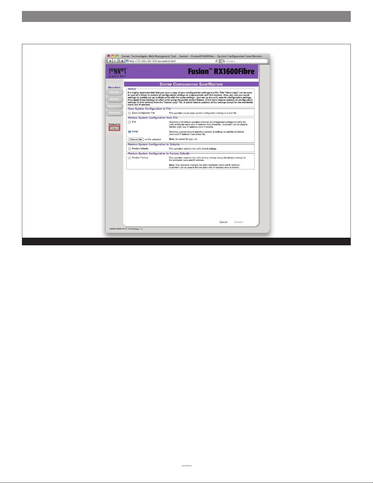
2.0 Manage Sonnet Devices, Configurations
System Configuration Save/Restore page
Figure 40
45
Page 52

46
Page 53

2.1 Interface Options
The best way to manage, monitor and configure the Fusion RX1600Fibre
is to use the ExpressNAV Storage Manager, a browser-based application
installed in your system, but you may use a terminal emulation program
or Telnet.
Using the Sonnet Web Management Tool
Use the Sonnet Web Management Tool to manage, monitor and
configure the RX1600Fibre and any attached RX1600 Expansion
systems. The choices you make lead you from screen to screen.
Choices which are not available are greyed out.
Note: The RX1600Fibre is initially configured with DHCP enabled. It
is best if you have access to a DHCP server.
1. Work from the computer attached to the RX1600Fibre’s
Ethernet port. From the CD supplied with your system, run
the QuickNav Utility QuickNAV-Mac for Mac OS X or
QuickNAV-windows.exe for Windows.
2. Locate the RX1600Fibre with the serial number recorded
earlier.
3. Highlight the serial number.
4. Click Next. If a DHCP server is available on your network,
an address is assigned automatically by the server. Note the
assigned address. If you do not have a DHCP server, get an IP
address and subnet mask from your network administrator,
type it into the area provided, and click Next.
5. Click Launch Browser. Your browser points to the Sonnet
Web Management Tool splash screen. Press Return (Enter).
6. Type in the user name and password values.
Note: The default values are user name: root and password: Password.
The user name is case insensitive and the password is case
sensitive. It is best practice to change the user name and
password. Refer to Changing the Current User Name, Password
on page 17.
The pages which next appear depend on whether or not you
have begun configuring the RX1600Fibre.
Using the Serial Port
To connect to a terminal emulation program to manage the
RX1600Fibre, use the serial port.
1. Connect the supplied cable between the RX1600Fibre’s serial
port and a personal computer or server’s serial (COM) port.
2. Start a terminal emulation program on the computer, and
use it to connect to the RX1600Fibre. For example, if you are
using Hyper Terminal on a computer running a Windows
operating system:
a. Type Fusion RX1600Fibre in the New Connection dialog
box.
b. Click OK.
c. In the Connect To dialog box in the Connect using field,
select the COM port number to which your serial cable is
connected.
d. Click OK.
e. In the COM Properties dialog box select the following
values:
• Bits per second: 115200
• Data Bits: 8
• Parity: None
• Stop Bits: 1
• Flow Control: None
• Terminal type: ASCII
• Echo: off
f. Click OK.
3. Turn on the RX1600Fibre.
4. After you connect to the RX1600Fibre, startup messages
are displayed. The last line in the startup message sequence
is Ready. Make adjustments to the RX1600Fibre using the
Command Line Interface as described in CLI Provides an
ASCII-Based Interface on page i of the Appendix.
Note: In serial port sessions, there is no prompt on the line below the
word Ready. Begin typing commands in the blank line where the
cursor is resting. No user name or password is required for serial
port access.
5. To verify that you have connected successfully, type help
after the Ready prompt and press Return (Enter). If a list
of all available commands does not appear on the screen,
review the steps in this section, check the cable, or contact
service personnel until the problem is solved. If you have
difficulty using the serial port, verify that you have the
correct settings and that your serial cable is less then two
meters in length.
47
Page 54

2.1 Interface Options
Using Telnet
Up to three Telnet sessions using the Fusion RX1600Fibre’s
Ethernet management port can be conducted simultaneously. A
serial port session can use the CLI while Telnet sessions are open.
Whichever session issues the first set CLI command that requires
a SaveConfiguration can continue to issue set commands, while
the other sessions can only issue get commands or display
information. Once a connection is established, refer to CLI
Provides an ASCII-based Interface on page i of the Appendix.
1. Connect to the RX1600Fibre from a computer on the same
Ethernet network.
2. Start a Telnet session.
Note: There is more than one way to connect to the FastStream using
a Telnet program. Your Telnet program may operate differently
than in the following instructions.
3. At the Telnet prompt, issue the open command
telnet > open x.x.x.x
where x.x.x.x is the IP address of the RX1600Fibre.
4. If you have to specify a port type, type in the port type
“telnet” and the terminal type “SC100”.
port type: telnet
terminal type: SC100
5. Type in the default values for the user name root and
the password Password if you did not set new values in
Changing the Current User Name, Password on page 17.
48
Page 55

2.2 Update Firmware
Firmware updates are available on the Sonnet Web site.
The ATTO FastStream controller in the Fusion RX1600Fibre has
several processors which control the flow of data. The firmware
to control these processors can be upgraded in the field using
the Sonnet Web Management Tool. Be sure all data is backed up
before updating firmware to prevent data loss.
WARNING: Ensure that all I/O to the RX1600Fibre has
stopped. During this procedure, do not interrupt the
update process.
1. The Fusion RX1600Fibre firmware is distributed as an image
file (.ima). Download the appropriate firmware file from the
Sonnet Web site (http://www.sonnettech.com/support/)
or insert the Installation CD containing the file into your
computer.
2. If you’re not already in the Sonnet Web Management Tool,
type the IP address of your RX1600Fibre in a standard
browser. On the splash screen, click Enter Here. In the box
provided, type in your user name and password, and then
click OK.
3. The Health and Status Monitor page appears.
4. Click the Diagnostics button on the left side of the window.
5. The Diagnostics menu page appears. From the Select User
Process box, select Update the Firmware.
6. Click Next. The Firmware Update page appears. See
Figure 41 on page 50.
7. If you know the name and location of the .ima file, enter it
into the text box provided. If you do not know the file name
and location, click Browse to navigate to the new firmware
and click it until the file name appears in the text box.
8. Click Upload.
WARNING: Do not power down the host or the
RX1600Fibre. Interrupting the update process makes your
Fusion storage system inoperable and you must return it to Sonnet
for repair.
9. Wait for a success message to be displayed.
10. Click Restart.
11. When the Diagnostics menu page appears your new
firmware has been uploaded and installed.
49
Page 56

2.2 Update Firmware
Update RX1600Fibre firmware to add features and improve usability
Figure 41
50
Page 57
Appendix A - CLI ASCII-Based Interface
The command line interface (CLI) uses ASCII commands typed in the
CLI window.
WARNING: Do not use CLI unless you are directed to by
a Sonnet technician, as changing parameters may cause
loss of data and/or disruption to performance and reliability
of the Sonnet RAID controller. The Sonnet Web Management
Tool is the preferred tool to operate and manage the Fusion
RX1600Fibre and attached Fusion RX1600 Expansion systems.
The command line interface (CLI) is a set of ASCII-based
commands which perform configuration and diagnostic tasks.
You may use them through the Sonnet Web Management Tool
Advanced CLI page (refer to Advanced CLI page on page 35) or
by using the serial port interface or the Ethernet management
port (refer to Interface Options on page 47).
• CLI commands are context sensitive and generally follow a
standard format
[Get|Set] Command [Parameter1|Parameter2]
followed by the return or enter key
• CLI commands are case insensitive: you may type all upper
or all lower case, or a mixture. Upper and lower case in this
manual and the help screen are for clarification only.
• The get form returns the value of a parameter or setting and is
an informational command.
• Responses to get commands are followed by Ready.
• The set form is an action that changes the value of a parameter
or configuration setting. It may require a SaveConfiguration
command and a restart of the system before it is
implemented. The restart can be accomplished as part of
the SaveConfiguration command or by using a separate
FirmwareRestart command. A number of set commands may
be issued before the SaveConfiguration command.
• Responses to set commands are either an error message
or Ready. *. The asterisk indicates you must use a
SaveConfiguration command to finalize the set command.
• Set commands which do not require a SaveConfiguration
command, defined as immediate commands, are immediately
executed.
Support Note: Using certain CLI commands during
normal operation can cause a performance drop. Once
command actions are complete, performance should return to
normal levels.
• Commands generally have three types of operation: get, set and
immediate.
Figure A-1 Symbols, typefaces, and abbreviations used to indicate functions and elements of the command line interface used in this manual.
Symbol Indicates
– A range (6 – 9 = 6, 7, 8, 9)
… Indicates optional repetition of the preceding item
[ ] Required entry
| Pick one of
< > Optional entry
EnclosureIndex Index designation of an enclosure found by using the SESIdentify command
fl Fibre Channel LUN ID (0 <= fl <= 31)
fp Fibre Channel port number (1 <= fp <= 2)
GroupName The name of the RAID group, designated by the user, to which a block device is assigned. Use RGDisplay to discover
RAID group names
MemberIndex Index designation of a RAID group member as found in the RMStatus command
mp1 Ethernet port used to manage the FastStream
PartitionIndex Index designation of a partition as found by using the PartitionDisplay command
i
Page 58

Appendix A - CLI ASCII-Based Interface
CLI Error Messages
The following error messages may be returned by the Command
line Interface
ERROR Invalid Command. Type “Help“ for command list.
ERROR Wrong/Missing Parameters
Usage: <usage string>
ERROR Invalid RAID Group State
ERROR Invalid Block Device index
ERROR Invalid RAID Member index
ERROR Maximum number of RAID Groups exceeded
ERROR Insufficient number of RAID Group members
ERROR Block Device at specified index no longer
available
ERROR Insufficient RAID Group members for RAID type
CLI Summary
The following chart summarizes the Command Line Interface
commands, their defaults, and an example of how to enter the
commands. Please note that commands which have no default
values have a blank entry in that column of the table.
WARNING: Do not use the CLI unless you are directed
to by a Sonnet technician, as changing parameters may
cause loss of data and/or disruption to performance and
reliability of the Fusion storage system.
Command Default Example
AutoMap automap
AutoResume initialize = enabled
rebuild = enabled
erase = disabled
BlockDevClean blockdevclean 30
BlockDevIdentify blockdevidentify alpha 3
BlockDevIDStop blockdevidstop
BlockDevScan blockdevscan
BootDelay 5 set bootdelay 25
BridgeModel get bridgemodel
BridgeName set bridgename Omega6
ClearEventLog cleareventlog
Date set date 03/03/2009
DeleteAllMaps deleteallmaps
DisplayEventLog displayeventlog
DisplayEventLogFilter all all all set displayeventlogfilter gen info all
DriveTest drivetest begin
set autoresume all disabled
DriveTestConfig not initiated set drivetestconfig read
DriveTestList get drivetestlist all
DriveTestStatus get driveteststatus
DumpConfiguration dumpconfiguration
ii
Page 59

Appendix A - CLI ASCII-Based Interface
Command Default Example
DumpEventLog dumpeventlog
EmailFromAddress set emailfromaddress
EmailNotify disabled set emailnotify enabled
EmailNotifyAddress get emailnotifyaddress
EmailPassword set emailpassword
EmailServerAddress 0.0.0.0 get emailserveraddress
EmailUsername get emailusername
EthernetSpeed auto set ethernetspeed mp1 100
EventLog enabled set eventlog disabled
EventLogFilter all all all set eventlogfilter gen info all
Exit exit
FCConnMode loop set fcconnmode all ptp
FCDataRate auto get fcdatarate all
FCHard disabled set fchard enabled
FCHardAddress fp1=3; fp2=4, fp3=5, fp4=6 set fchardaddress 1 122
FCMultiNode disabled set fcmultinode enabled
FCPortErrors get fcporterrors all
FCPortList fcportlist
FCWWName get fcwwname 1
FirmwareRestart firmwarerestart
Help help eventlog
HSAdd hsadd 3
HSDisplay hsdisplay
HSRemove hsremove 3
IdentifyBridge disabled set identifybridge enabled
Info info
IPAddress 10.0.0.1 get ipaddress mp1
IPDHCP enabled set ipdhcp mp1 disabled
IPDNSServer set ipdnsserver mp1 172.15.12.123
IPGateway 0.0.0.0 get ipgateway mp1
IPSubnetMask 255.255.0.0 get ipsubnetmask mp1
IsReserved isreserved
MaxOpTemp 70 get maxoptemp
Metrics metrics display all
MinOpTemp 0 set minoptemp 10
OpTempWarn 5 set optempwarn 15
Partition partition alpha1 6 4 GB
iii
Page 60

Appendix A - CLI ASCII-Based Interface
Command Default Example
PartitionDisplay partitiondisplay alpha1
PartitionMerge partitionmerge all
PartitionWriteCache set partitionwritecache enabled
PartitionSplit partitionsplit alpha1 22 2
PassThroughMode disabled set passthroughmode all
PassThroughPersistent passthroughpersistent
PassThroughRediscover passthroughredicsover
Password Password set password
Performance get performance 2
Ping ping mp1 192.42.155.155
RAIDRebuildPriority same set raidrebuildpriority low
RAIDSpeedWriteLimit 8 set raidspeedwritelimit 16
ReadOnlyPassword Password set readonlypassword
ReadOnlyUsername user set readonlyusername
Reserve reserve
ResetFCPortErrors resetfcporterrors 1
RestoreConfiguration restoreconfiguration default
RGAddStorage rgaddstorage groupname1 span commit
RGAutoRebuild disabled set rgautorebuild all enabled
RGCancelAddStorage rgcanceladdstorage groupname1
RGCommit rgcommit all
RGCreate rgcreate groupname1 raid0
RGDelete rgdelete groupname1
RGDiskWriteCache set rgdiskwritecache g1 enabled
RGDisplay rgdisplay all
RGErase rgerase groupname1
RGHaltConversion rghaltconversion groupname1
RGHaltErase rghalterase groupname1
RGHaltInitialization rghaltinitialization groupname1
RGHaltRebuild rghaltrebuild groupname1
RGMemberAdd rgmemberadd groupname1 30
RGMemberRemove rgmemberremove groupname1 30
RGPrefetch 0 rgprefetch groupname1 2
RGRebuild rgrebuild groupname1
RGResumeConversion rgresumeconversion groupname1
RGResumeErase rgresumeerase groupname1
RGResumeInitialization rgresumeinitialization groupname1
iv
Page 61

Appendix A - CLI ASCII-Based Interface
Command Default Example
RGResumeRebuild rgresumerebuild groupname1
RGSectorSize 512 setrgsectorsize groupname1 8192
RGSpanDepth 1 set rgspandepth groupname1 22
RGSpeedRead auto set rgspeedread groupname1 enabled
RGUnmap rgunmap groupname1
RMStatus rmstatus groupname1
Route route fc 1 0 raid alpha1 6
RouteDisplay routedisplay fc
SASPortList
SASTargets sastargets
SaveConfiguration saveconfiguration
SerialNumber get serialnumber
SerialPortBaudRate 115200 set serialportbaudrate 19200
SerialPortEcho enabled get serialportecho
SES enabled set ses disabled
SESAlarmTest sessalarmtest 22 set
SESDiskFailureAlarm disabled set sesdiskfailurealarm enabled
SESEnclosures sesenclosures
SESIdentify off set sesidentify all
SESIdentifyStop sesidentifystop all
SESMute
SESPoll 30 set sespoll 0
SESStartingSlot 1 set sesstartingslot 2
SESStatus sesstatus
SNTP enabled get sntp
SNTPServer 192.43.244.18 set sntpserver 129.6.15.28
TailEventLog taileventlog
Temperature get temperature
Time set time 03:32:30
TimeZone EST set timezone pst
UserName root set username Binky
VerboseMode enabled set verbosemode disabled
VirtualDriveInfo virtualdriveinfo
WrapEventLog enabled set wrapeventlog disabled
zModem zmodem receive
v
Page 62

Appendix A - CLI ASCII-Based Interface
CLI Command Explanations
Command line interface commands are listed alphabetically with
explanations of what they are used for, their defaults and syntax.
WARNING: Using CLI without contacting a Sonnet
technician is not recommended because changing
parameters may cause loss of data and/or disruption to
performance and reliability of the Fusion storage system.
• AutoMap (Immediate, Disabled on Error)
Automatically assigns a subset of source protocol LUNs to a
subset of target destination devices visible to the unit. The
unit reports a five-second delay while it scans for devices. All
previous maps are deleted.
If FCMultiNode is enabled (multiple node):
AutoMap <fp>
SaveConfiguration command required
If FCMultiNode is disabled (single node):
AutoMap
SaveConfiguration command required
• AutoResume
Regulates the AutoResume features for interrupted rebuild and
erase operations at startup. If no group name is specified, all
existing RAID groups are affected.
Default: enabled for AutoResume Rebuild, Initialize disabled for
AutoResumeErase
set AutoResume [Rebuild | Erase |Initialize |
All ] [enabled | disabled] <group name>
• BlockDevClean (Immediate, Disabled on Error)
Removes any RAID configuration data from the block device
with the specified block ID.
BlockDevClean [BlockDevID]
WARNING: All RAID group setup information is lost
when the BlockDevClean command is performed,
therefore all data is lost. Back up your files before performing
this command.
• BlockDevIdentify (Immediate, Disabled on Error)
Turns on a drive activity LED on the Fusion drive enclosure for
a specified drive until a BlockDevIDStop command is given.
Use either RAID group name and member index, or block ID.
WARNING: The BlockDevIdentify command is intended
for diagnostic purposes only. Executing this command may
adversely impact the performance and throughput of the Fusion
storage system for the time that the LED is illuminated.
BlockDevIdentify <Groupname> [BlockDevID | member
index]
• BlockDevIDStop (Immediate, Disabled on Error)
Turns off the previously identified disk drive‘s activity LED.
BlockDevIDStop
• BlockDevScan (Immediate, Disabled on Error)
Lists all currently-connected drives and any potential RAID
group association. Each drive listed is assigned a unique index
at the time of the scan which is used to identify drives for other
CLI operations.
BlockDevScan
• Boot Delay
Regulates the delay (in seconds) which the unit waits after
startup before allowing hosts to detect target devices. The value
0 produces no delay.
Default: 5
set BootDelay [0-255]
get BootDelay
• BridgeModel
Reports specific model and firmware information.
get BridgeModel
• BridgeName
Specifies an ASCII name assigned to the unit to identify
individual units. It is not the World Wide Name. Changes
take effect immediately. The name may be contain up to 8
characters.
set BridgeName [name]
SaveConfiguration Restart command required
get BridgeName
• ClearEventLog (Immediate)
Clears the contents of the EventLog. No new entries are
recorded until the operation is completed.
ClearEventLog
vi
Page 63

Appendix A - CLI ASCII-Based Interface
• Date
Sets/displays the current date. The date range is 01/01/2000 to
12/31/2099.
set Date [MM]/[DD]/[YYYY]
get Date
• DeleteAllMaps (Immediate, Disabled on Error)
Removes all mapped devices from the map table. Upon the
subsequent POST, the default maps are loaded if no maps are
present.
DeleteAllMaps
SaveConfiguration command required
• DisplayEventLog (Immediate, Disabled on Error)
Displays the EventLog. The event log may be filtered using the
DisplayEventLogFilter command. The optional parameter n is
the number of lines to be displayed as a single page with no
user interaction. After the command has executed, use +, - or =
to scroll through the log. Type quit and press Return (Enter) to
exit the command.
DisplayEventLog <n>
• DisplayEventLogFilter (Immediate, Disabled on Error)
Filters the display of data for specified subsystems and levels
during DisplayEventLog mode. Valid event log subsystem
entries are platform-dependent. For set commands, the final
parameter indicates whether or not events from the specified
subsystem and level are displayed.
Default: all all all
set DisplayEventLogFilter [subsystem | all]
[level | all] [all | none]
get DisplayEventLogFilter [subsystem |all]
[level | all]
• DriveTest (Immediate, Disabled on Error)
Starts or stops a drive test with the previously specified
configuration. Drives being tested are not available for RAID
configuration or RAID operations. Only one test can be run at
a time.
DriveTest [Begin | Cancel]
• DriveTestClearList
Configures the next drive test to perform one of the
following operations: initialize (destructive write-only), read
(nondestructive read-only), verify (destructive verify), or initverify (destructive write-read-verify). The test is not started until
the DriveTest Begin command is given.
set DriveTestConfig [init | read | verify |
init-verify]
get DriveTestConfig
• DriveTestConfig (Disabled on Error)
Configures the next drive test to perform one of the
following operations: initialize (destructive write-only), read
(nondestructive read-only), verify (destructive verify), or initverify (destructive write-read-verify). The test is not started until
the DriveTest Begin command is given.
set DriveTestConfig [init | read | verify |
init-verify]
get DriveTestConfig
• DriveTestList (Disabled on Error)
Specifies drives to be run in the next drive test. This command
can be called with different eligible block IDs and each one is
added to the list. Drives which are not part of a RAID group or
are not hot spares are eligible. The all parameter automatically
chooses eligible drives. The test is not started until the DriveTest
Begin command is given..
set DriveTestList [drive [BlockDevID] | all]
get DriveTestList
• DriveTestStatus
Displays the status of the currently running drive test but
does not display performance metrics. If a block device ID is
not running or cannot be found, its state is idle and percent
complete is 0.
get DriveTestStatus <drive [BlockDevID]>
• DumpConfiguration (Immediate)
Displays the unit’s configuration to the Advanced page of the
Sonnet Web Management Tool or a terminal emulation or
Telnet session. The record may not be displayed completely in
the Sonnet Web Management Tool page.
DumpConfiguration
• DumpEventLog (Immediate)
Displays the contents of the EventLog to the Advanced page of
the Sonnet Web Management Tool or a terminal emulation or
Telnet session. The record may not be displayed completely in
the Sonnet Web Management Tool page.
DumpEventLog
• EmailFromAddress
Configures the Email address that the unit uses to communicate
with the Email server. Full Email address is a fully qualified
Internet Email address, not more than 128 characters long.
set EmailFromAddress [full email address]
get EmailFromAddress
vii
Page 64

Appendix A - CLI ASCII-Based Interface
• EmailNotify
Regulates Email notification.
Default: disabled.
set EmailNotify [enabled | disabled]
get EmailNotify
• EmailNotifyAddress
Configures notification addresses. Index is a number between
1 and 5. Full Email address is a fully qualified Internet Email
address, not more than 128 characters long. Emails are sent
based on the warning level you set to trigger an Email alert.
Warning levels
None: no Emails
Critical: only critical severity events
Warning: warnings and critical events
Informational: information
All: all warnings, critical events and informational messages
set EmailNotifyAddress [index] [full email
address] [warning level]
get EmailNotifyAddress <index | all>
• EmailPassword
Configures the password which authenticates the login to the
SMTP Email server. The password must not be more than 64
characters. A password is not required if the Email server does
not require authentication.
set EmailPassword
SaveConfiguration command required
• EmailServerAddress
Configures the address of the server the unit must contact in
order to send out Email notifications using either an Email
address (xxx.xxx.x.x) or a fully qualified domain name (mail.
myserver.com).
Default: 0.0.0.0
set EmailServerAddress [IP address |domain
name]
SaveConfiguration command required
get EmailServerAddress
• EmailUsername
Configures the user name which authenticates the login to the
SMTP Email server. The user name must not be more than 128
characters. A user name is not required if the Email server does
not require authentication.
set EmailUsername [username]
SaveConfiguration command required
get EmailUsername
• EthernetSpeed
Regulates the speed of the RX1600Fibre’s Ethernet port. If Auto
is enabled, the Ethernet speed is negotiated. When hard set, 10
and 100 speeds are half duplex.
Default: auto
set EthernetSpeed [mp1] [10 | 100 | auto]
SaveConfiguration Restart command required
get EthernetSpeed [mp1]
• EventLog (Enabled, Disabled on Error)
Regulates event logging. When enabled, records various system
errors to the event log.
set EventLog [enabled | disabled]
get EventLog
• EventLogFilter (Enabled, Disabled on Error)
Filters data from specific unit subsystems and levels when event
logging is enabled. The specific entries supported are platformdependent. For set commands, the final parameter indicates
whether or not events from the specified subsystem and level
are displayed.
set EventLogFilter [subsys | all] [eventlevel |
all] [all | none]
get EventLogFilter [subsys | all] [eventlevel |
all]
• Exit (Immediate)
Terminates the current CLI session over Telnet. This command
has no effect if used during a serial CLI session.
Exit
viii
Page 65

Appendix A - CLI ASCII-Based Interface
• FCConnMode
Specifies the connection mode the unit uses when
communicating across a Fibre Channel network.
Connection modes:
FC_AL arbitrated loop: loop
Point-to-point: ptp
auto-negotiation, loop preferred: loop-ptp
auto-negotiation, ptp preferred: ptp-loop:
Default: loop
set FCConnMode [fp| all] [loop | ptp | loop-ptp
| ptp-loop]
SaveConfiguration Restart command required
get FCConnMode [fp | all]
• FCDataRate
Specifies the Fibre Channel data rate at which operation will
occur. If no connection has been made, the data rate in the Info
command output toggles among 1Gb, 2Gb or 4Gb on hardware
capable of 4Gb per sec., and 8Gb on hardware capable of 8Gb
per sec.
set FCDataRate [fp | all] [1Gb | 2Gb | 4Gb |
8Gb | auto]
get FCDataRate [fp | all]
• FCHard
Regulates Fibre Channel hard address assignment. When
enabled, the unit tries to use its internal hard address as its
address on the Fibre Channel loop. Under soft addressing, the
unit loop address is assigned during loop initialization.
Default: disabled
set FCHard [enabled | disabled]
SaveConfiguration Restart command required
get FCHard
• FCHardAddress
Specifies the value used as the FC-AL hard address. This
value represents the address that will be used if the FCHard
command is enabled. Valid Fibre Channel hard address values
are from 0 through 125.
set FCHardAddress [fp | all] [address]
get FCHardAddress [fp | all]
• FCMultiNode
Determines the reported identity of Fibre Channel ports. When
enabled (multiple node mode), each port reports a separate
unique Node Name; logical units may be mapped to any port.
When disabled (single node), each port reports the same Node
Name and each logical unit map is applied to all ports.
Support Note: Changing the FC port reporting causes
all maps to be deleted: you must perform a
SaveConfiguration command before creating new maps using
the AutoMap or Route commands.
Default: disabled
set FCMultiNode [enabled | disabled]
get FCMultiNode
• FCPortErrors
Displays the number of Fibre Channel errors that have occurred
since the last reboot/power-on or use of the ResetFCPortErrors
command.
get FCPortErrors [fp | all]
• FCPortList
Displays a list of available FC ports and their current status.
Valid reported status values are Up, Down, Failed, Reserved
and Disabled.
FCPortList
• FCWWName
Reports the World Wide Port Name of the Fibre Channel
interface referenced. Each Fibre Channel port has an individual
and unique 8-byte Port Name.
get FCWWName [fp | all]]
• FirmwareRestart
Resets and reinitializes the unit firmware. Use the forced option
to override any CLI reservations held by other sessions.
FirmwareRestart <forced>
• Help (Immediate)
Displays a list of available commands. If command name is
specified, displays detailed command-specific information
Help <command>
• HSAdd (Immediate)
Assigns a drive to the Hot Spare pool. If RAID and RAID group
name are specified, the Hot Spare is assigned only to the specified
RAID group. If no group name is specified, the Hot Spare is a
global Hot Spare and available for use by any RAID group.
HSAdd <RAID Group Name> [BlockDevID]
ix
Page 66

Appendix A - CLI ASCII-Based Interface
• HSDisplay (Immediate)
Lists all drives in the Hot Spare pool.
HSDisplay
• HSRemove (Immediate)
Removes a drive from the Hot Spare pool
HSRemove [BlockDevID | all]
• IdentifyBridge (Immediate)
When enabled, the fault LED on this unit blinks so that
hardware may be identified. Disabling this option cancels the
blinking..
Default: disabled
set IdentifyBridge [enabled | disabled]
get IdentifyBridge
• Info (Immediate)
Displays version numbers and other production information for
key components. Use the optional “brief” parameter to display
a more concise subset of system information.
Info <brief>
• IPAddress
Controls the current IP address of the RX1600Fibre’s Ethernet
port. If IPDHCP is enabled, the get command reports the
current IP address assigned by the network DHCP server,
followed by the DHCP identifier.
Default: 10.0.0.1
set IPAddress [mp1] [xxx.xxx.xxx.xxx]
SaveConfiguration Restart command required
get IPAddress [mp1]
• IPDHCP
Regulates how the unit acquires its IP address. When disabled,
the unit uses the IP address specified by the IPAddress CLI
command; when enabled, the unit gets its IP address from a
DHCP server.
Default: enabled
set IPDHCP mp1 [enabled | disabled]
SaveConfiguration Restart command required
get IPDHCP
• IPDNSServer
Controls the current DNS Server address. If IPDHCP is enabled,
the DNS Server address is automatically detected. If IPDHCP
is disabled, you must set the address manually using this
command.
set IPDNSServer mp1 [xxx.xxx.xxx.xxx]
get IPDNSServer
• IPGateway
Controls the current default gateways used by the
RX1600Fibre’s Ethernet port. If IPDHCP is enabled, the get
command reports the current IP gateway assigned by the
network DHCP server.
Default: 0.0.0.0
set IPGateway [mp1] [xxx.xxx.xxx.xxx]
SaveConfiguration Restart command required
get IPGateway [mp1]
• IPSubnetMask
Controls the current subnet masks used by the RX1600Fibre’s
Ethernet port. If IPDHCP is enabled, the get command reports
the current IP subnet mask assigned by the network DHCP
server.
Default: 255.255.0.0
set IPSubnetMask [mp1] [xxx.xxx.xxx.xxx]
SaveConfiguration Restart command required
get IPSubnetMask [mp1]
• IsReserved (Immediate)
Displays the reservation status of the current services session or
interface.
IsReserved
• MaxOpTemp
Regulates or lists the maximum operating temperature. Valid
entries are from 55 through 70°Celsius.
Default: 70
set MaxOpTemp [55 – 70]
SaveConfiguration Restart command required
get MaxOpTemp
x
Page 67

Appendix A - CLI ASCII-Based Interface
• Metrics (Immediate)
Controls the collection of standard data metrics within a
product based on the command parameters.
Metrics [Start | Stop | Display] [drive
[BlockDevID] | all | running]
• MinOpTemp
Regulates or lists the minimum operating temperature. Valid
entries are from 0 through 15° Celsius.
Default: 0
set MinOpTemp [0 – 15]
SaveConfiguration Restart command required
get MinOpTemp
• OpTempWarn
Regulates or lists the offset when a warning is issued before a
thermal control event. Valid entries are from 0 to 15° Celsius.
Default: 5
set OpTempWarn [0 – 15]
SaveConfiguration Restart command required
get OpTempWarn
• Partition (Immediate)
Creates a specified partition to the specified capacity in
Gigabytes (GB), Megabytes (MB), or blocks. The specified
capacity must be smaller than the specified partition’s current
capacity. A new partition is created to acquire the remainder of
the original partition’s space.
Partition [GroupName] [PartIndex] [capacity] [GB
| MB | blocks]
• PartitionDisplay (Immediate)
Lists all the partitions available in the specified RAID group. The
partitions are listed contiguously (as opposed to index order).
GroupName is the ASCII name of the RAID Group for which
partitions will be displayed.
PartitionDisplay [GroupName]
• PartitionMerge (Immediate)
Merges the specified contiguous partitions into one partition.
GroupName is the ASCII name of the RAID Group containing
the partitions to merge. PartIdx is the index of a partition to
merge, along with a number of contiguous partitions to merge
to that index.
Group will be merged into a single Virtual Disk. The RAID
Group must not be in a NEW state. None of the partitions to
merge may be mapped.
PartitionMerge [GroupName] [[[PartIdx] [2-128]] |
All]
• PartitionSplit (Immediate)
Divides the specified partition into one or more partitions
whose capacities are evenly distributed among the capacity of
the original partition. GroupName is the ASCII name of the
RAID Group containing the partition to split. PartIdx is the
index of the partition to split. The partition to split cannot be
mapped and the RAID group must not be in a NEW state.
PartitionSplit [GroupName] [PartIdx] [2-128]
• PartitionWriteCache
If enabled, RAID internal Write Cache performs with a higher
write rate providing a small risk of data loss after a system
failure. If disabled, RAID internal Write Cache performs at a
higher level of data integrity with lower write performance..
set PartitionWriteCache [GroupName] [PartIdx]
[enabled | disabled]
get PartitionWriteCache [GroupName] [PartIdx]
• PassThroughMode
Specifies the non-disk device types which are automatically
mapped at startup. Use all to map all non-disk devices. Use SES
to map dedicated SES processor LUNs. Use non-SES to map all
non-SES devices. Use disabled to disable the passthrough mode.
Default: disabled
set PassThroughMode [all | SES | non-SES |
disabled]
get PassThroughMode
• PassThroughPersistent
Stores maps for currently-attached passthrough devices to
persistent memory.
PassThroughPersistent
All indicates that all partitions in the RAID
• PassThroughRediscover
Makes any previously-deleted pass through target devices visible
to the host.
PassThroughRediscover
xi
Page 68

Appendix A - CLI ASCII-Based Interface
• Password
Specifies the password used for all sessions: Telnet, FTP and
Sonnet Web Management Tool. Password is case sensitive, from
0 through 32 characters, and cannot contain spaces. Configure
an empty password by pressing Return (Enter) when asked to
designate a new password and confirmation.
Default: Password
set Password
• Performance
Lists performance data for the specified Fibre Channel port
including the average rate (MB/sec.) and number of I/Os
measured over the previous sampling period. Samples are taken
about every second. Successful SCSI Read (08h, 28h) and Write
(0Ah, 2Ah) commands are considered I/Os.
get Performance <fp>
• Ping
Sends an ICMP echo request to the specified host.
ping [mp1] [xxx.xxx.xxx.xxx] <count <size>>
• RAIDRebuildPriority
Sets or displays the RAID rebuild priority. A RAID rebuild
priority set to high gives higher priority to RAID rebuilds and
lower priority to the processing of simultaneous read/write
transactions. A RAID rebuild priority set to low gives lower
priority to the rebuild and a higher priority to read/write
transactions. Set to same, the RAID rebuild and processing of
read/write transactions is the same.
Default: same
set RAIDRebuildPriority <GroupName | all> [high
| low | same]
SaveConfiguration command required
get RAIDRebuildPriority <GroupName | all>
• RAIDSpeedWriteLimit
Specifies or displays the limit on the RAID Speed Write
function. Warning: Changing the default setting (8) may result in
poor performance or timeouts. A lower setting is recommended
when using multiple initiators. A higher setting may improve
performance with multiple streams of sequential write I/O, but
too high a setting will cause timeouts.
Default: 8
set RAIDSpeedWriteLimit [0–256]
get RAIDSpeedWriteLimit
• ReadOnlyPassword
Specifies a password which allows only read and no writes. It is
case sensitive, 0 to 32 characters, and cannot contain spaces. An
empty password can be configured by not specifying one.
Default: Password
set ReadOnlyPassword
• ReadOnlyUsername
Specifies the user name which allows only read and no writes.
It is case insensitive, 1 to 32 characters, and cannot contain
spaces.
Default: user
set ReadOnlyUsername [username]
get ReadOnlyUsername
• Reserve (Immediate)
Reports the state of CLI reservation for the current CLI session.
If the command reports that Reservations are enabled, then
another CLI session has control of parameter modification on
the unit.
Reserve
• ResetFCPortErrors
Resets all Fibre Channel error counts for the specified port to
zero.
ResetFCPortErrors [fp | all]
• RestoreConfiguration (Immediate, Disabled on Error)
Use default to force the NVRAM setting to its original defaults.
Use factory to force the NVRAM setting to its original defaults,
including the unit's World Wide Name (WWN). Use saved to
undo any changes made since the last save.
RestoreConfiguration [default | factory | saved]
• RGAddStorage (Immediate)
Adds additional storage to an existing RAID group. Warning:
This feature is not supported under Mac OS X. Up to 10 indices
of available block devices, provided by the BlockDevScan
command, may be added to the RAID group. If this list is
omitted, use RGMemberAdd instead of RGAddStorage. If you
use Commit to automatically save the configuration, all user
data is removed from each new member drive. If you do not
use Commit, you must use the command RGCommit to save
the configuration. If you do not use the Commit parameter
and you have not used RGCommit, you may use the command
RGCancelAddStorage. Note: Mirrors cannot be added to a RAID 4,
RAID 5, RAID 6, or DVRAID RAID group.
RGAddStorage [GroupName] [Mirror | Stripe |
Span] <BlockDevID… <commit>
xii
Page 69

Appendix A - CLI ASCII-Based Interface
• RGAutoRebuild
RGAutoRebuild enables and disables Auto-Rebuild functionality
for one or more RAID Groups. Auto-Rebuild uses drives
assigned as Hot Spares, followed by all other available drives, as
automatic replacements for any member that fails. Auto-
Default: disabled
set RGAutoRebuild [GroupName | all] [enabled |
disabled]
get set RGAutoRebuild [GroupName | all]
• RGCancelAddStorage (Immediate, Disabled on Error)
Cancels the RGAddStorage command.
RGCancelAddStorage [GroupName]
• RGCommit (Immediate, Disabled on Error)
Saves a RAID group’s configuration to its member drives. If you
add storage to an existing RAID group, the additional storage is
stamped with the existing group’s configuration. Use Advanced
to initialize new drives, erasing and verifying the drive media;
the RAID group is unavailable until the operation completes. Use
Express to perform a background initialization; the RAID group
is immediately available for use.
RGCommit < GroupName <Advanced | Express> |
all <Advanced | Express> >
• RGDisplay (Immediate)
Displays status information for a single RAID group, or if All is
used, all available RAID groups.
RGDisplay <GroupName | all>
• RGErase (Immediate)
Erases the data from the specified existing RAID group.
Warning: All data is lost when you use the RGErase command!
RGErase [GroupName]
• RGHaltConversion (Immediate)
Stops the conversion on the specified existing RAID group.
RGHaltConversion [GroupName]
• RGHaltErase (Immediate)
Stops the erase on the specified RAID group.
RGHaltErase [GroupName]
• RGHaltInitialization (Immediate)
Stops the initialization process on the specified existing RAID
group.
RGHaltRebuild [GroupName]
• RGCreate (Immediate)
Creates a new RAID group with the name, RAID level and
interleave level, if specified. KB denotes interleave in kilobytes.
Without the KB suffix, interleave is set in 512 byte blocks. If
interleave is not provided, the system’s default interleave is used.
RGCreate [Group Name] [RAID [0|1|10|4|5|6] |JBOD]
<8KB|16KB|32KB|64KB|128KB|256KB|512KB|1024 KB |16|32
|64|128|256|512|1024|2048>
• RGDelete
Deletes all RAID group configurations or the specified RAID
group configuration.
RGDelete [group name | all]
RGDisplay <GroupName | all>
• RGDiskWriteCache (Immediate)
If enabled, produces higher write performance with a small risk
of data loss after a system failure. If disabled, drives are updated
at the expense of some write performance.
set RGDiskWriteCache [GroupName | all] [enabled
| disabled]
get RGDiskWriteCache [GroupName | all]
• RGHaltRebuild (Immediate)
RGHaltRebuild halts the rebuild(s) on the specified existing
RAID Group. Optional parameter MemberIndex specifies
the RAID Member whose rebuild will be halted. For RAID 6
Groups, if a MemberIndex is specified, all rebuilding RAID
Members on the span with that MemberIndex will halt as
well. If no MemberIndex is specified, all rebuilds on that RAID
Group will be halted.
RGHaltRebuild [GroupName] <MemberIndex>
• RGMemberAdd (Immediate)
Adds available block devices to a new RAID group or as part
of an RGAddStorage operation and resets the number of
RAID partitions to 1. Up to 10 block IDs may be specified. If
all is specified, then all available unused blocks are added to
the RAID group until the maximum number of RAID group
members has been met.
RGMemberAdd [GroupName | all] [BlockDevID]
• RGMemberRemove (Immediate)
Removes a RAID member from a new RAID group and resets
the number of partitions to 1.
RGMemberRemove [GroupName] [MemberIndex]
xiii
Page 70

Appendix A - CLI ASCII-Based Interface
• RGPrefetch
Specifies or lists the prefetch value..
set RGPrefetch [GroupName | all] [Value 0 to 6]
get RGPrefetch [GroupName | all]
• RGRebuild (Immediate)
Starts rebuilding the specified existing RAID Group. Optional
parameters MemberN specify the members to rebuild. If no
member is specified, all degraded members will be rebuilt.
Optional parameters BlockDevID1 allows an available block
device to be substituted for the RAID Member currently
assigned to the Member Index. RAID 6 groups can rebuild two
members using the optional and.
RGRebuild [GroupName] <Member1> <BlockDevID1>
<and> <Member2> <BlockDevID2>
• RGResumeConversion (Immediate)
Continues the stopped conversion on the specified existing
RAID group.
RGResumeConversion [GroupName]
• RGResumeErase (Immediate)
Continues the erase on the specified existing RAID group.
RGResumeErase [GroupName]
• RGResumeInitialization (Immediate)
Continues the initialization on the specified existing RAID
group.
RGResumeInitialization [GroupName]
• RGResumeRebuild
Continues the rebuild on a RAID group. For RAID 6 groups,
if a Member Index is specified, all rebuilds stopped on the
span with that Member Index resume. If no Member Index is
specified, all stopped rebuilds on that RAID Group are resumed.
RGResumeRebuild [Group Name] <Member Index>
• RGSpanDepth
Regulates the span depth on the specified existing new
RAID group for all RAID configurations except JBOD, which
implicitly supports spanning as members are added.
set RGSpanDepth [GroupName] [SpanDepth [1-16]]
get RGSpanDepth [GroupName]
• RGSpeedRead
Performs look-ahead during reads from RAID group member
disks for all or the specified RAID group. Choose Auto to base
the read algorithm on each I/O command.
set RGSpeedRead [GroupName | all] [enabled |
disabled | auto]
get RGSpeedRead [GroupName | all]
• RGUnmap (Immediate)
Removes all mapped partitions of the specified RAID group from
the routing table. The partitions themselves will be unaffected,
though they will now be inaccessible to any initiators.
RGUnmap [GroupName | all]
• RGWaitTimeout (Disabled on Error)
Specifies the maximum time in seconds that the system waits
to discover previously-configured RAID groups. The time out
is used during system boot time and when the BlockDevScan
command is issued.
Default: 5
set RGWaitTimeout [1-3600]
SaveConfiguration Restart command required
get RGWaitTimeout
• RMStatus (Immediate)
Lists the status of all RAID members within a RAID group or a
specific RAID member.
RMStatus [GroupName] <MemberIndex>
• RGSectorSize
Set or get the sector size of the specified RAID Group. The
desired RAID Group sector size must be evenly divisible by the
sector size of any member disk. 512 bytes is the default size for
most operating systems. Use 4K sectors to enable large volume
support (greater than 2TB, up to 16TB) in Windows XP (32-bit).
Default: 512
set RGSectorSize [GroupName] [512-8192]
get RGSectorSize [GroupName]
• Route
Maps a RAID partition or SAS/SATA PassThrough device onto
the Fibre Channel network as an FC LUN (SCSI-FCP LUN).
Mapping a RAID partition to a current FC LUN overwrites
the previous map. If the unit is configured for verbose mode,
overwriting a map requires secondary confirmation.
If FCMultiNode is enabled:
Route FC [fl] [ [RAID [Group Name] [Part Index]]
| [SAS [SAS Index]]| Delete ]
If FCMultiNode is disabled:
Route FC [fl] [ [RAID [Group Name] [Part Index]]
| [SAS [SAS Index]]| Delete ]
xiv
Page 71

Appendix A - CLI ASCII-Based Interface
• RouteDisplay (Immediate)
Lists all maps with RAID group partition identifier, group
name and FC LUN (SCSI-FCP LUN). Use Passthrough to list
only passthrough device maps. Use Persistent to list only Pass
Through maps stored in persistent memory.
If FCMultiNode is enabled:
RouteDisplay FC <LUN> | <passthrough> |
<persistent>
If FCMultiNode is disabled:
RouteDisplay FC <LUN> |<passthrough> |
<persistent>
• SASPortList (Immediate)
Lists the status of all available SAS ports.
SasPortList
• SASTargets (Immediate, Disabled on Error)
Lists the physical devices that are connected to all SAS ports.
SASTargets
• SaveConfiguration (Immediate, Disabled on Error)
Issued with the restart option, cycles unit power after saving
configuration changes. The norestart option saves changes
without restarting. Note: Certain modifications require a system
restart.
SaveConfiguration
• SerialNumber
Displays the serial number. The serial number is a 13 character
field. The first seven alphanumeric characters are an abbreviation
representing the product name. The remaining six digits are the
individual unit’s number.
get SerialNumber
• SerialPortBaudRate
Configures the baud rate for the unit’s RS-232 serial port. The
number of data bits per character is fixed at 8 with no parity.
Default: 115200
set SerialPortBaudRate [9600 | 19200 | 38400 |
57600 | 115200]
SaveConfiguration Restart command required
get SerialPortBaudRate
• SerialPortEcho
Controls if the unit echoes characters on its RS-232 port. When
enabled, all non-control character keyboard input is output to
the display.
Default: enabled
set SerialPortEcho [enabled | disabled]
get SerialPortEcho
• SES (Enabled, Disabled on Error)
Enables support for SES enclosures that have been discovered by
the controller.
set SES [enabled | disabled]
get SES
• SESAlarmTest (Immediate, Disabled on Error)
Turns on an enclosure's audible alarm if certain conditions
exist. Reset turns off the alarm. Use SESEnclosures before
setting the alarm.
SESAlarmTest [EnclIdx] [SET | RESET] [INFO |
NON-CRIT | CRIT | UNRECOV]
• SESDiskFailureAlarm (Disabled, Disabled on Error)
When enabled, activates an audible alarm when the RAID
controller determines that a RAID member disk drive has failed.
The alarm in the enclosure which contains the failed disk drive
will sound, other enclosures will be unaffected.
set SESDiskFailureAlarm [enabled | disabled]
get SESDiskFailureAlarm
• SESEnclosures (Immediate, Disabled on Error)
Displays a list of SES-enabled enclosures which have been
discovered by the controller.
SESEnclosures
• SESIdentify (Disabled on Error)
Commands the SES enclosure to identify the specified element.
ALL identifies all disks. RAID and RAID group name identify all
disks in a RAID group. If the Member Index is also specified,
only that disk is identified. ENC and enclosure index identify
all slots in the specified enclosure. DRIVE and BlockDevID
identify the specified disk. Use SESEnclosures first before
identifying elements using ALL or ENC. If using ENC, use
BlockDevScan first.
set SESIdentify [ALL | RAID Group Name
<Member Index> | ENC Enclosure Index | DRIVE
BlockDevID]
get SESIdentify [ALL | RAID Group Name
<Member Index> | ENC Enclosure Index | DRIVE
BlockDevID]
xv
Page 72

Appendix A - CLI ASCII-Based Interface
• SESIdentifyStop (Immediate, Disabled on Error)
Commands an SES enclosure to stop identifying the specified
element. ALL stops identifying all enclosure drive slots. RAID
and RAID group name stop identifying disks in a RAID
group. ENC and enclosure index stop identifying all slots
in the enclosure. DRIVE and BlockDevID stop identifying
the specified drive. Use SESEnclosures first before identifying
elements using ALL or ENC.
SESIdentifyStop [ALL | RAID Group Name
<Member Index> | ENC Enclosure Index | DRIVE
BlockDevID]
• SESMute (Immediate, Disabled on Error)
Causes the audible alarms of all known enclosures or the
specific enclosure to be muted or set to the remind state if
supported. The remind state causes an occasional audible
reminder of the alarm condition. Use SESEnclosures first before
using this command.
Default: Mute
SESMute <EnclIdx> <REMIND>
• SESPoll (Enabled, Disabled on Error)
Specifies the SES enclosure polling interval in seconds. At the
specified interval, all known SES enclosures are polled for their
current status. A setting of 0 disables SES enclosure polling.
Default: 60
set SESPoll [0 | 30-3600
get SESPoll
• SESStartingSlot (Disabled on Error)
SESStartingSlot establishes the starting slot/ID number for all
attached SES enclosures.
set SESStartingSlot [0 | 1]
get SESStartingSlot
• SESStatus (Immediate, Disabled on Error)
SESStatus displays the last polled status of the specified element
type in the specified enclosure. SupportLevel indicates the
SES features supported by the specified enclosure: Fan, Power,
Temp, Alarm, DriveLEDs. If no element type is specified, all
status is displayed. Note that SESEnclosures must be executed
prior to executing SESStatus.
SESStatus [EnclIdx] <ENC | DRIVE | FAN | POWER
| TEMP | ALARM | SUPPORTLEVEL>
• SNTP
Controls whether an SNTP time server is used to set the date
and time.
Default: enabled
set SNTP [enabled | disabled]
SaveConfiguration Restart command required
get SNTP
• SNTPServer
Regulates or lists the main IP address the client uses to retrieve
the SNTP time and date.
Default: 192.43.244.18
set SNTPServer [xxx.xxx.xxx.xxx]
SaveConfiguration Restart command required
get SNTPServer
• TailEventLog
Displays new events to the terminal. Type quit then press
return (Enter) to exit tail mode.
TailEventLog
• Temperature
Lists the current internal operating temperature in degrees
Celsius. The value is read-only.
get Temperature
• Time (Disabled on Error)
Sets or displays the current time as in 24 hour format.
set Time [HH: MM: SS]
get Time
• TimeZone
Sets or displays the time zone or an offset from GMT. GMT
offset must be in the format +/-HH:MM
Default: EST
set TimeZone [[EST | CST | MST | PST] | [[+|-]
[HH]:[MM]]]
SaveConfiguration Restart command required
get TimeZone
xvi
Page 73

Appendix A - CLI ASCII-Based Interface
• Username
Specifies the user name for all sessions: Telnet, FTP and Sonnet
Web Management Tool. It is case insensitive, from 1 through 32
characters, and cannot contain spaces.
Default: root
set Username [username]
SaveConfiguration command required
get Username
• VerboseMode (Enabled)
Controls the level of detail in CLI Help output and command
response output for the current CLI session.
Default: enabled
set VerboseMode [enabled | disabled]
get VerboseMode
• VirtualDriveInfo (Immediate)
Displays characteristics and statistics for all the available virtual
drives or any available virtual drive identified by its virtual
drive ID.
VirtualDriveInfo <Virtual Drive ID>
• WrapEventLog (Enabled, Disabled on Error)
When enabled, the unit logs up to 2,048 event entries before
wrapping (overwriting the first entries). If disabled, the unit
stops logging event entries when the buffer is full.
Default: enabled
set WrapEventLog [enabled | disabled]
get WrapEventLog
• zModem
Transfers a file using the RS-232 port and the zModem protocol.
You must type in the file name to send a file.
zModem [[send [file name]] | receive]
xvii
Page 74

xviii
Page 75

Appendix B - RAID Group Designs
The ATTO FastStream controller in the Fusion RX1600Fibre
provides instant hardware data protection and intelligence to
existing storage independent of the storage type.
JBOD (Just a Bunch of Disks)
WARNING: RAID improves data accessibility and
reliability during normal operations, however, you
still need a good backup strategy for long-term protection
of your data.
To set up RAID groups refer to Configure Storage into RAID
Groups on page 7. The Fusion RX1600Fibre allows RAID
functionality. In general, the process begins with individual
drives called block devices.
Note: If a drive has corrupt or outdated configuration data, that
drive cannot be assigned to any RAID group. Ensure all drives are
configured properly. Refer to Ensure Drive Integrity on page 3 or
Removing RAID configuration data on page 34.
A RAID group is a virtual, independent single drive whose
data is written to physical drives according to a RAID
algorithm. The ATTO FastStream supports JBOD, DVRAID,
RAID Level 0, 1, 1+ 0, 4, 5 and 6.
RAID improves data accessibility and reliability during
normal operations, however, you still need a good backup
strategy for long-term protection of your data.
JBOD: Just a Bunch of Disks
JBOD configuration allows many individual drives to be
available for normal storage operations with no special data
protection by combining several drives into one large drive.
See Figure B-1. A special case of a RAID group, multiple
physical drives are assigned to a JBOD RAID group and
their storage areas appear as a single spanned area of storage.
The Fusion RX1600Fibre supports 1 to 32 drives per JBODconfigured RAID group.
Disk 1 Disk 2 Disk 3
Data 1 Data 5 Data 9
Data 2 Data 6 Data 10
Data 3 Data 7 Data 11
Data 4 Data 8 Data 12
Figure B-1
RAID Level 0: Striping, No Redundancy
Stripe 1
Stripe 2
Stripe 3
Disk 1
Data 1
Data 5
Data 9
Disk 2
Data 2
Data 6
Data 10
Figure B-2
Disk 3
Data 3
Data 7
Data 11
Disk 4
Data 4
Data 8
Data 12
RAID Level 0: Striping, No Redundancy
RAID Level 0 (striping) is based on the fact that increased
performance can be achieved by simultaneously accessing
data across multiple drives, increasing data transfer rates
while reducing average access time by overlapping drive
seeks. Drives are accessed alternately, as if stacked one on top
of the other. RAID Level 0 provides no data protection. If
one drive fails, all data within that stripe set is lost. See
Figure B-2.
RAID Level 0 is used by applications requiring high
performance for non-critical data. The Fusion RX1600Fibre
supports 2 to 16 drives per RAID Level 0 group.
xix
Page 76

Appendix B - RAID Group Designs
RAID Level 1: Mirroring (Duplicate Drives)
RAID Level 1 ensures the security of data by writing the
exact same data simultaneously to two different drives. With
RAID Level 1, the host sees what it believes to be a single
physical drive of a specific size: it does not know about the
mirrored pair. This application is used for critical data which
cannot be at risk to be lost or corrupted due to the failure of
a single drive. See Figure B-3.
RAID Level 1: Mirroring (Duplicate Drives)
Disk 1
Disk 2
The Fusion RX1600Fibre supports an even number of 2 to 16
drives per RAID Level 1 group.
RAID Level 1 Plus Additional Mirroring
RAID Level 1 with multiple mirrors uses at least 3 drives
with the same data on each drive. This application offers the
highest fault-tolerance with good performance, especially for
small database applications. See Figure B-4.
Data 1
Data 2
Data 3
Figure B-3
Data 1
Data 2
Data 3
RAID Level 1 Plus Additional Mirroring
Disk 1
Data 1
Data 2
Disk 2
Data 1
Data 2
Disk 3
Data 1
Data 2
RAID Level 1+0: Striping, Mirror Spans Two
Drives
RAID Level 1+0 increases data transfer rates while ensuring
security by writing the exact same data simultaneously to
two or more different drives. RAID Level 1+0 is used in
applications requiring high performance and redundancy,
combining the attributes of RAID Levels 1 and 0. See
Figure B-5.
The Fusion RX1600Fibre supports an even number of 4 to 16
drives per RAID Level 1+0 group.
Stripe 1
Stripe 2
Stripe 3
xx
Data 3
Data 3
Figure B-4
Data 3
RAID Level 1+0:
Striping, Mirror Spans Two Drives
Disk 1
Data 1
Data 3
Data 5
Disk 2
Data 1
Data 3
Data 5
Figure B-5
Disk 3
Data 2
Data 4
Data 6
Disk 4
Data 2
Data 4
Data 6
Page 77

Appendix B - RAID Group Designs
RAID Level 4: Striping, One Parity Drive
RAID 4 writes data across multiple drives or devices (striping)
with parity blocks written to a single drive in the RAID
group. This increases reliability while using fewer drives than
mirroring. RAID Level 4 is best suited for applications that
perform mostly sequential access such as video applications.
See Figure B-6.
You must have at least three drives to set up RAID Level 4.
RAID Level 4: Striping, One Parity Drive
Disk 1
Disk 2
Disk 3
Disk 4
DVRAID: Digital Video RAID
Digital Video RAID provides parity redundancy for your
data. Optimized for performance for the high data transfer
rates required in digital video environments, DVRAID is
ATTO Technology proprietary technology which supports
the editing of uncompressed 10-bit High Definition (HD)
video and multiple streams of real-time, uncompressed
Standard Definition (SD) video. See Figure B-7.
You must use the Quick Digital Video setup wizard in the
Sonnet Web Management Tool.
Stripe 1
Stripe 2
Stripe 3
Stripe 1
Stripe 2
Stripe 3
Data 1
Data 4
Data 7
Data 2
Data 5
Data 8
Figure B-6
Data 3
Data 6
Data 9
Parity 1–3
Parity 4–6
Parity 7–9
DVRAID: Striping, One Parity Drive
Disk 1
Data 1
Data 4
Data 7
Disk 2
Data 2
Data 5
Data 8
Disk 3
Data 3
Data 6
Data 9
Parity 1–3
Parity 4–6
Parity 7–9
Disk 4
RAID Level 5: Striping, Parity Distributed
Among Drives
RAID Level 5 increases reliability while using fewer drives
than mirroring by using parity redundancy: parity is
distributed across multiple drives. See Figure B-8.
The Fusion RX1600Fibre supports 3 to 16 drives per RAID
Level 5 group.
Figure B-7
RAID Level 5:
Striping, Parity Distributed Among Drives
Stripe 1
Stripe 2
Stripe 3
Stripe 4
xxi
Disk 1
Data 1
Data 5
Data 9
Parity
10–12
Disk 2
Data 2
Data 6
Parity 7–9
Data 10
Figure B-8
Disk 3
Data 3
Parity 4–6
Data 7
Data 11
Disk 4
Parity 1–3
Data 4
Data 8
Data 12
Page 78

Appendix B - RAID Group Designs
RAID Level 6: Striping, Two Parity Blocks
Distributed Among Drives
RAID Level 6 increases reliability for mission critical
applications by striping both data and dual parity across
multiple drives, writing data and parity blocks across all the
drives in a RAID group. RAID 6 provides can tolerate failure
of two drives and provides redundancy during rebuilds. See
Figure B-9.
The Fusion RX1600Fibre requires at least four drives to build
a RAID 6 group. Two drives per RAID group are used for
parity protection and are unavailable for data.
RAID Level 6: Striping, Two Parity Blocks
Distributed Among Drives
Disk 1
Data 2
Data 6
Parity 7–9
Disk 2
Data 3
Parity 4–6
Parity 7–9
Disk 3
Parity 1–3
Parity 4–6
Data 7
Stripe 1
Stripe 2
Stripe 3
Disk 1
Data 1
Data 5
Data 9
Disk 4
Parity 1–3
Data 4
Data 8
Stripe 4
Parity
10–12
Parity
10–12
Data 10
Figure B-9
Data 11
Data 12
xxii
Page 79

Appendix C - Multipathing
The Fusion RX1600Fibre supports multipath I/O through its
ATTO FastStream RAID storage controller, a technique that
enhances performance and fault tolerance, combining data paths
from two or more Fibre Channel ports to increase performance
and provide redundancy in case of a port or cable malfunction,
the leading causes of storage failure. Multipathing additionally
provides load balancing to distribute I/O across multiple paths for
improved system and application performance.
For environments where storage availability and increased
performance are important, it is recommended that you take
advantage of the ATTO FastStream controller’s Failover and Load
Balancing functionality.
The FastStream storage controller is compatible with generic
Multipathing for Windows, OS X and Linux, however best results
are achieved and supported with the ATTO Windows DSM MPIO
driver and ATTO Celerity Multipathing for OS X.
Setup instructions for ATTO Celerity Multipathing for OS X
and ATTO Windows DSM MPIO can be found on the software
CD included with the Fusion RX1600Fibre, and may also be
downloaded from the Sonnet Web site. Setup instructions for Red
Hat and SuSE Linux Multipathing can be found on the same disc.
Load Balancing Algorithms for OS X and Windows
DSM MPIO
Pressure: The path with the fewest number of bytes being
transferred is selected for I/O. Pressure load balancing is domainbased. The first level of path selection is based on the domain
(adapter channel) with the fewest number of bytes being
transferred. If there are multiple paths to a target on a domain, a
second level of selection is used. Pressure load balancing provides
the best (or equal) performance of all load balancing policies
regardless of storage topology.
Queue Depth: The path with the fewest outstanding I/O
transactions is selected for I/O. This target-based policy is not
generally recommended for use in an environment with mixed
I/O transfers to many devices.
Round Robin: The least-used path is selected for I/O. This targetbased policy uses the configuration’s cumulative I/O count
for path selection. For example, if an I/O operation starts and
finishes on one path to a dual ported device, the second path is
used when the next I/O operation starts.
Setup of the RX1600Fibre with Multipathing
Multipathing functionality is set up and controlled from the
Fibre Channel host adapter; minimal interaction is required on
the RX1600Fibre. When the RX1600Fibre’s FastStream storage
controller is used with any multipathing technology, it must
have MultiNode functionality disabled. This can be set via the
Advanced CLI page with the command “FCMultiNode disabled”
or from the Sonnet Web Management Tool from the Manage
Menu > System Configuration > Establish Access through FC
Ports (this must be set to Yes). No other setting changes are
required in order for multipathing compatibility.
Improved Availability of Storage With Improved
Performance
Multipathing Failover: Redundant physical path components host adapters, SFPs, cables and switches are used to create logical
paths between the server and the storage device. In the event that
one or more of these components fails, causing the path to fail,
ATTO Multipathing logic uses an alternate path for I/O so that
applications can still access their data.
Multi-Load Balancing: Multipathing software also serves to
redistribute the read/write load among multiple paths between
the server and storage, thereby helping to remove bottlenecks
and to balance workloads for better overall performance.
xxiii
Page 80

xxiv
Page 81

Appendix D - Quick Drive Reformat Instructions
If your Sonnet Fusion RAID storage system shipped with pre-installed
hard disk drives, the following information will assist you to reformat
the drives per your needs.
In Fusion RX1600 systems shipped from Sonnet with hard
disk drives installed, the drives are formatted Mac OS Extended
(Journaled), and configured as a single RAID 6 RAID group.
If you need to change the configuration, use the Sonnet Web
Management Tool interface and the operating system software
tools to reformat and reconfigure the drives.
Mac OS Users’ Instructions
1. Follow all the steps in the included documentation to install
the software and the Sonnet Fibre Channel host adapter,
and to set up and connect the Fusion RX1600Fibre drive
enclosure.
2. Start your computer, and then turn on the Fusion drive
enclosure; the RAID volume should appear on the desktop.
3. Drag the volume to the trash (changes to an eject icon) to
eject it.
4. Log into the Sonnet Web Management Tool.
11. Repeat steps 8–10 for each remaining unformatted RAID
group.
12. Close Disk Utility.
13. Depending on how you configured the RAID groups, the
volumes may already be available to the system. If you
created a DVRAID, RAID 4, RAID 5, or RAID 6 RAID group,
configuration will take much longer. You may check on the
progress by clicking the Monitor button to the left of the
window.
14. Once all the RAID groups have been formatted and finish
building, they are ready to use.
Windows Vista Users’ Instructions
1. Follow all the steps in the included documentation to install
the software and the Sonnet RAID controller, and to set up
and connect the Fusion RAID enclosure.
2. Start your computer, and then turn on the Fusion drive
enclosure.
3. Log into the Sonnet Web Management Tool.
5. Delete the RAID group as described in Deleting RAID
Groups on page 31.
6. Set up new RAID groups following the instructions in
Configure Storage into RAID Groups starting on page 7.
WARNING: After selecting the DVRAID, RAID Level 4,
RAID Level 5, or RAID Level 6 option, configuration of
the drives will take several hours to complete, with the
total time depending on the operating system and drive
capacities.
7. Depending on how you configure your setup, a Disk
Insertion window will appear at some point stating that there
is an unreadable volume; click Initialize, and then Disk
Utility will open.
8. In the Disk Utility window, each RAID group you created
using the ATTO Configuration Tool will appear as a single
volume. Select the volume, and then click the Erase tab at the
top of the window.
Support Note for Power Mac G5 Users: When
creating RAID groups 16TB or larger, uncheck the Install
Mac OS 9 Drivers checkbox; OS 9 drivers do not support volumes
greater than 16TB.
9. Click Erase; a window will appear asking you to approve
your choice.
10. Click Erase.
4. Delete the RAID group as described in Deleting RAID
Groups on page 31.
5. Set up new RAID groups following the instructions in
Configure Storage into RAID Groups starting on page 7.
WARNING: After selecting the DVRAID, RAID Level 4,
RAID Level 5, or RAID Level 6 option, configuration of
the drives will take several hours to complete, with the
total time depending on the operating system and drive
capacities.
6. Select Computer Management From the Windows Start
menu. If Computer Management is not available in the Start
Menu, select Start > Control Panel > Administrative Tools.
In the Administrative Tools window, double-click Computer
Management.
7. In the Computer Management window, click Storage on the
left, and then double-click Disk Management.
8. When the Initialize Disk window appears, select the RAID
volume you created. Select the MBR partition style if you
need to access your RAID storage from a computer running
Windows XP Professional or 32-bit Windows Server 2003;
otherwise, select GPT. Click OK.
9. In the Disk Management window, each RAID group you
created will appear (listed as “unallocated”) as a single volume.
Right-click where the word “unallocated” appears, and then
select New Simple Volume.
xxv
Page 82
Appendix D - Quick Drive Reformat Instructions
Windows Vista Users’ Instructions (continued)
10. When the Welcome to the New Simple Volume Wizard window
appears, click next to start the process.
11. Follow the remaining steps to complete the process.
Note: If you do not select the quick format option, this process will take
much longer to complete.
12. When the Assign Drive Letter or Path window appears, select
Assign the following drive letter, choose a letter, and then
click Next.
13. When the Format Partition window appears, enter a new
name for the volume table if you’d like. For RAID volumes
up to 16TB, accept the default allocation unit size; for RAID
volumes greater than 16TB, select 8192 from the drop-down
menu. Select Perform a quick format, and then click Next.
14. When the next window appears, click Finish.
15. Repeat steps 9–14 for each remaining “unallocated” disk.
16. Depending on how you configured the RAID groups, the
volumes may already be available to the system. If you
created a DVRAID, RAID 4, RAID 5, or RAID 6 RAID group,
configuration will take much longer. You may check on the
progress by clicking the Monitor button to the left of the
window.
17. Once all the RAID groups have been formatted and finish
building, they are ready to use.
Windows XP/Server 2003 Users’ Instructions
1. Follow all the steps in the included documentation to install
the software and the Sonnet RAID controller, and to set up
and connect the Fusion RAID enclosure.
2. Start your computer, and then turn on the Fusion drive
enclosure.
3. Log into the Sonnet Web Management Tool.
4. Delete the RAID group as described in Deleting RAID
Groups on page 31.
5. Set up new RAID groups following the instructions in
Configure Storage into RAID Groups starting on page 7.
WARNING: After selecting the DVRAID, RAID Level 4,
RAID Level 5, or RAID Level 6 option, configuration of
the drives will take several hours to complete, with the
total time depending on the operating system and drive
capacities.
6. Select Computer Management From the Windows Start menu.
If Computer Management is not available in the Start Menu,
select Start > Settings > Control Panel > Administrative Tools.
In the Administrative Tools window, double-click Computer
Management.
7. In the Computer Management window, click Storage on the
left, and then double-click Disk Management.
8. When the Initialize and Covert Disk Wizard window appears,
click OK.
9. When the Select Disks to Initialize window appears, select the
RAID volume(s), and then click Next.
10. When the next window appears, click Finish.
11. In the Disk Management window, each RAID group you
created will appear (listed as “unallocated”) as a single volume.
Right-click where the word “unallocated” appears, and then
select New Partition.
12. When the Welcome to the New Partition Wizard window
appears, click Next.
13. When the Select Partition Type window appears, select Primary
Partition, and then click Next.
14. When the Specify Partition Size window appears, click next.
15. When the Assign Drive Letter or Path window appears, select
Assign the following drive letter, choose a letter, and then
click Next.
xxvi
Page 83

Appendix D - Quick Drive Reformat Instructions
Windows XP/Server 2003 Users’ Instructions
(continued)
16. When the Format Partition window appears, enter a new
name for the volume table if you’d like. For RAID volumes
up to 16TB, accept the default allocation unit size; for RAID
volumes greater than 16TB, select 8192 from the drop-down
menu. Select Perform a quick format, and then click Next.
17. When the next window appears, click Finish.
Note: If you do not select the quick format option, this process will take
much longer to complete.
18. Repeat steps 11–17 for each remaining “unallocated” disk.
19. Depending on how you configured the RAID groups,
the volumes may already be available to use. If you
created a DVRAID, RAID Level 4, or RAID Level 5 group,
configuration will take much longer. You may check on the
progress by clicking the Monitor button to the left of the
window.
20. Once all the RAID groups have been formatted and finish
building, they are ready to use.
xxvii
Page 84

Remember to register your product online at http://registration.sonnettech.com to be informed of future upgrades and product releases.
Software updates and links are available from the Sonnet web site at www.sonnettech.com. • Online support form available at http://supportform.sonnettech.com.
Sonnet Technologies Customer Service hours are Mon.-Fri., 7 a.m.–4 p.m. Pacific Time • Customer Service Phone: 1-949-472-2772 • Email: support@sonnettech.com
Sonnet Technologies, Inc., California USA • Tel: 1-949-587-3500 Fax: 1-949-457-6349
©2009 Sonnet Technologies, Inc . All rights reserved. Sonnet, the Sonnet logotype, Simply Fast, the Simply Fast logotype, and Fusion are trademarks of Sonnet Technologies, Inc. Macintosh and Mac are trademarks
of Apple Inc., registered in the United States and other countries. Other product names are trademarks of their respective owners. Product specifications subject to change without notice. Printed in the USA.
MNL-QUICKNAV-E-A-120909
 Loading...