

Page 1

Configuration Tool and Utilities
Operation Manual
for Fusion RAID Storage Systems
Page 2

Page 3

Contents
1.0 ATTO Configuration Tool Overview............................................................................................. 1
About the Configuration Tool
Configuration Tool Launch
Configuration Tool Navigation
Select the Local Host
Select the Controller
Select a Channel
Select a Device
1.1 RAID Controller NVRAM Settings............................................................................................... 7
SAS Address
Boot Driver
Heartbeat
NCQ
Device Wait Time
Device Wait Count
Spinup Delay
Multiplexing
PHY Speed
1.2 RAID Group Setup and Management.......................................................................................... 9
Preliminary Configuration Steps
Custom RAID Group Setup Steps
Hot Spares Setup and Usage
Mac OS Drive Formatting
Windows 7/Server 2008/Vista Drive Formatting
Windows XP/Server 2003 Drive Formatting
RAID Group Management Overview
RAID Group Capacity Expansion
RAID Group RAID Level Migration
RAID Group Deletion
RAID Group Rebuilding
RAID Group Properties Modification
1.3 Drive and RAID Group Monitoring............................................................................................ 17
Basic Drive Information
Detailed Drive Information
RAID Group Information
Drive Identification
S.M.A.R.T. Data
S.M.A.R.T. Monitoring Enabling and Disabling
S.M.A.R.T. Status Checking
S.M.A.R.T. Attribute Filtering
S.M.A.R.T. Notifications
1.4 Enclosure (SES) Health Monitoring.......................................................................................... 23
SES Status Checking
Page 4

Contents
1.5 RAID Event Notifications........................................................................................................ 25
Basic Alerts
Logging
Email Alerts
1.6 RAID Group Media Maintenance............................................................................................... 27
Media Scan Options
Start a Manual Media Scan
Schedule a Media Scan
Cancel, Pause, or Resume a Media Scan
Manage Scheduled Media Scans
Automatic Media Scan Cancellation
View a Scan Report
1.7 Identify and Replace a Faulted Drive.......................................................................................33
Automatic Faulted Drive Identification
Manual Faulted Drive Identification
Faulted Drive Replacement with Auto Rebuild
Manual Faulted Drive Replacement
1.8 Recover Data from Offline RAID Groups................................................................................... 35
Definitions
RAID Group Failure Scenarios
Drive Replacement on a Failure Condition
Replace RAID Group Members as Soon as They Fail
A Warning About Drive Replacement
Identifying Failed Drives
Recovery Mode
Recovery from a Failed Rebuild
Recovery from a Failed Rebuild with a Second Unrecoverable Drive Failure
Recovery from Faults on a Critical Number of Drives
Basic Recovery Mode
Extreme Recovery Mode
Recovery from Replacement of the Wrong Drive
File System Repair Tools
Mac OS X Users: Disk Utility
Windows Users: CHKDSK
Unix Users: FSCK
Using the CLI to Identify a Failed Drive
Using the CLI to Enable/Disable Recovery Mode
Using the CLI to to Enable Recovery with Writes
Page 5

Contents
1.9 SNMP Configuration................................................................................................................ 45
Definitions
Details
Enabled Mode
SubAgent Mode
Disabled Mode
Basic Setup
Configuration Options
Agent Port
Communities
Send Authentication Trap
Enable Traps
Trap Destination Table
Control Buttons
Commit
Restore
Default
Test
Save MIBs
Troubleshooting
Requests from an MIB browser time out:
Traps are not received when testing
RAID OIDs are skipped when walking or the tables are empty
1.10 Configuration Tool Troubleshooting........................................................................................ 51
Messages from NVRAM Tab Actions
An error occurred loading NVRAM data.
Warning: NVRAM could not be read, defaults returned.
An error occurred updating the NVRAM.
Feature bounds checking.
Execution Throttle is greater than the maximum allowable value of 255.
Messages from Flash Tab Actions
This is not a flash file, or it is corrupt.
This HBA is not compatible with the selected flash file.
A valid file was not selected.
An error occurred reading from the flash file, the file may be corrupt.
An error occurred updating the flash.
The card has been prepared for firmware updating…
2.0 Drive Performance Testing...................................................................................................... 53
2.1 Windows Only - ATTO Disk Benchmark..................................................................................... 55
Benchmark Fields
Radio Button Group
Multiple Benchmark Testing
2.2 ATTO Disk Benchmark Troubleshooting..................................................................................... 57
Page 6

Contents
Appendix A - CLI ASCII-Based Interface........................................................................................... i
CLI Error Messages
CLI Summary
CLI Command Explanations
Appendix B - Drive Reformat Instructions..................................................................................... xiv
Mac OS Users’ Instructions
Windows 7/Server 2008/Vista Users’ Instructions
Windows XP/Server 2003 Users’ Instructions
Page 7
1.0 ATTO Configuration Tool Overview
About the Configuration Tool
The ATTO Configuration Tool is the utility program that displays
information about installed controllers, drivers and drives in your
Fusion storage system, and provides the means to configure and
manage them.
This program executes under:
• Mac OS
• Windows
• Linux
Note: Java version 1.5 or later must be installed.
The ATTO Configuration Tool displays:
• The name of the Sonnet RAID controller (listed as an ExpressSAS
• Information about the drivers controlling the Sonnet RAID
• Information about Fusion drive enclosures attached to the
• Information about drives within attached Fusion drive enclosures
You may use the Configuration Tool to:
• Manage RAID groups
• Configure RAID Event notifications
• Modify the RAID controller’s NVRAM settings
• Revert to default factory settings
• Update the RAID controller’s flash image
• Obtain drive health information
• Obtain drive enclosure health information
The factory settings on your Sonnet RAID controller provide
excellent performance for a wide range of applications. However,
some applications may benefit from modification of the
controller’s NVRAM settings that tune the controller for a specific
performance range.
®
X 10.4 or later
®
7/Server 2008/Vista®/Server 2003/XP
®
2.4 and 2.6 kernels, x86 and x64
Rxxx adapter)
controller, including version information for both the currently
executing driver and the flash image
Sonnet RAID controller (except D400RAID, D800RAID, and
R800RAID) such as fan and power supply status
Configuration Tool Launch
1. Locate the application icon in the folder created during
installation.
2. Double-click the ATTO Configuration icon to start the
application.
WARNING: Back up system data when installing or
changing hardware configurations.
Note: The Sonnet RAID controller is designed to operate properly using
factory settings. Entering invalid or incorrect NVRAM settings
may cause your Sonnet RAID controller to function incorrectly.
The main screen has three panes: Device Listing, Configuration
Options and Status.
Configuration Tool Navigation
The Device Listing pane at the left of the window lists all
compatible devices (controllers and enclosures) currently
connected to the system.
Expand the device tree to reveal additional details on connected
devices.
Support Note: In the ATTO Configuration Tool’s Device
Listing pane, the Sonnet RAID controller is identified as an
ExpressSAS Rxxx.
The Configuration Options pane provides information and
options for a device highlighted in the device listing.
If you highlight a device in the Device Listing pane, tabs and
panes are displayed for that device.
The following chart specifies the tabs that are displayed for the
indicated device type:
Tree Node Tab(s) Displayed
Local Host Basic Info, Notifications, SNMP
Controller Basic Info, Flash, RAID, RAID CLI, Tasks,
Advanced
Channel NVRAM, Basic Info
Device Basic Info, Flash, SES
1
Page 8
1.0 ATTO Configuration Tool Overview
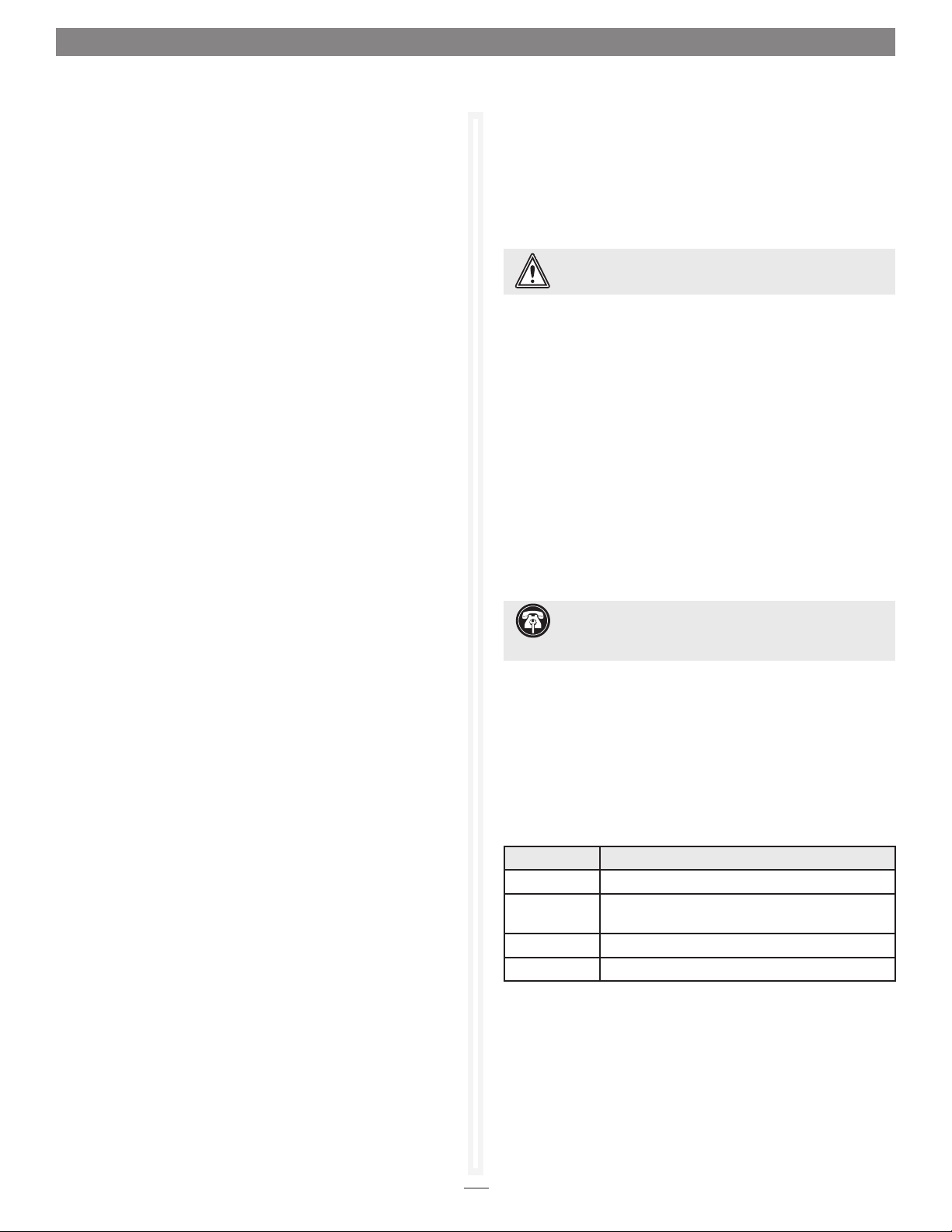
Select the Local Host
The following tabs display in the Configuration Options window
when you select the local host in the Device Listing window:
• The Basic Info tab displays information about the booted
operating system. See Figure 1 on page 3.
• The Notifications tab allows you to set up notification of
certain events in the Sonnet RAID controller. Refer to RAID
Event Notifications on page 23.
• The SNMP tab allows you to configure SNMP monitoring and
trap generation for the 3 Gb/s Sonnet RAID controller. Refer to
SNMP Configuration on page 45.
About window
The About window, displayed when About is selected from the
Help menu, lists the ATTO Configuration Tool’s version number.
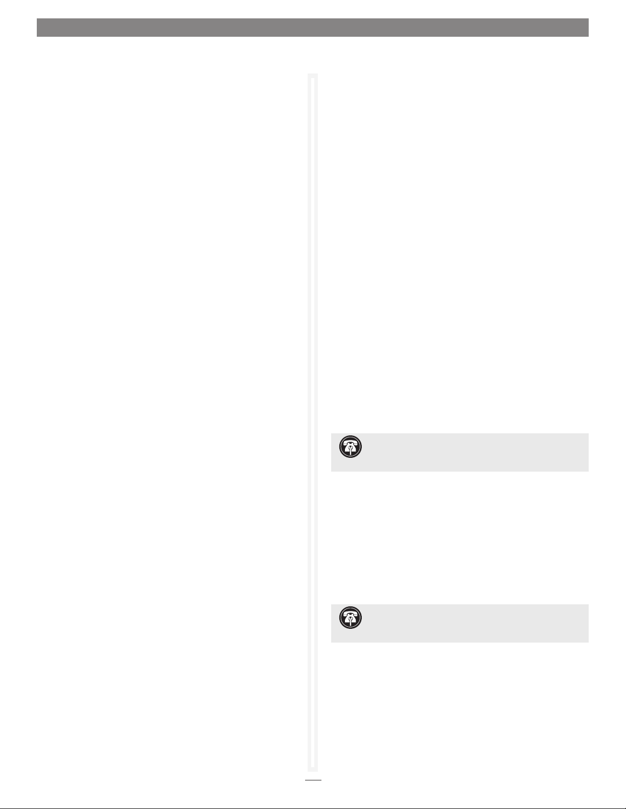
Select the Controller
The following tabs are displayed in the Configuration Options
pane when you select the Sonnet RAID controller in the Device
Listing pane:
• The Basic Info tab provides information about the Sonnet
RAID controller when it is highlighted in the Device Listing
pane. You cannot make changes from this screen. See Figure 2
on page 3.
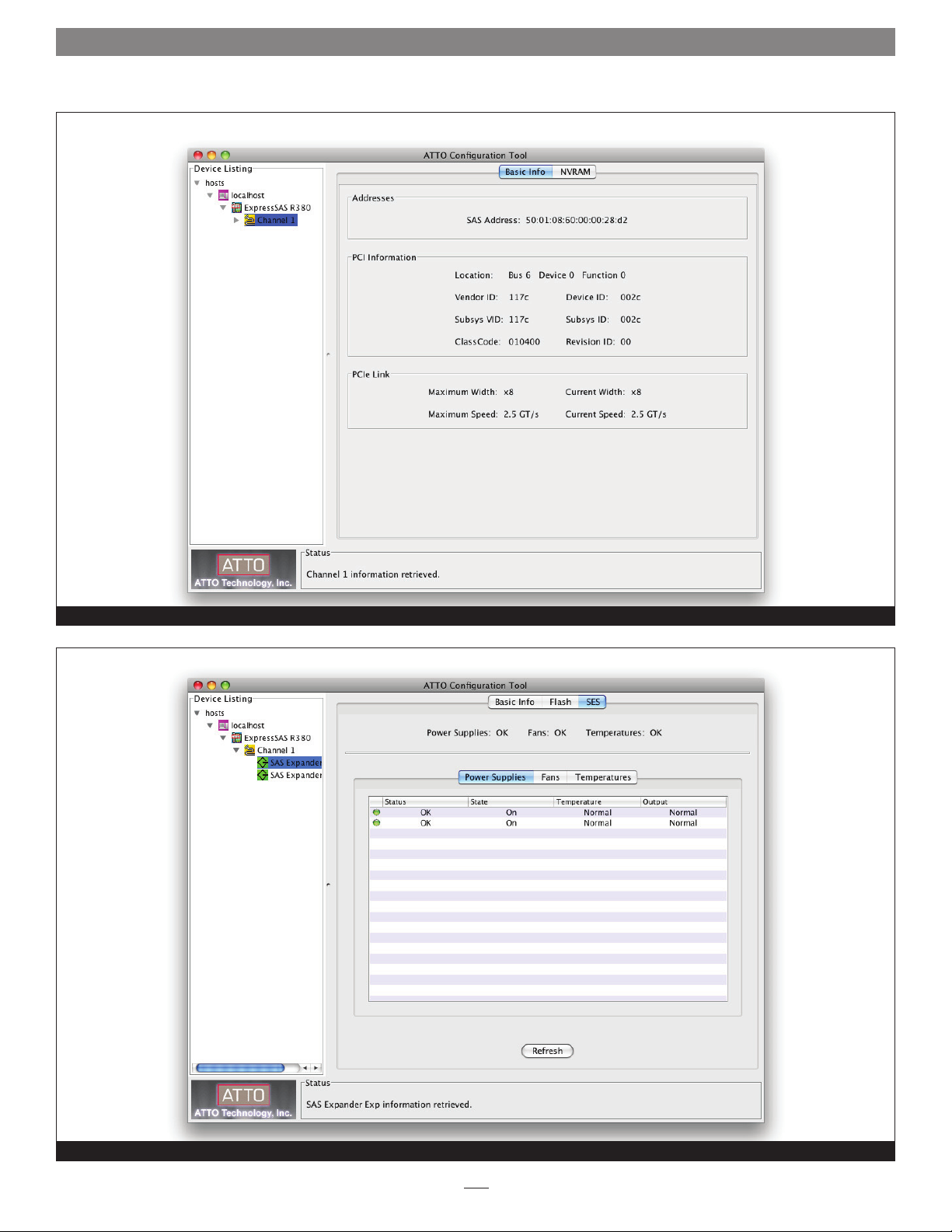
• The Tasks tab provides information about user-scheduled hard
drive health maintenance. In this tab, you can reschedule or
delete tasks. See Figure 6 on page 5.
• The Advanced tab does not function with the Sonnet RAID
controller; clicking this tab merely displays a message.
Select a Channel
The following tabs display in the right pane when you select a
specific channel in the Device Listing pane:
• When you select a specific channel under the Sonnet RAID
controller in the Device Listing pane, the NVRAM tab displays
the NVRAM parameters applicable to the Sonnet RAID
controller and channel selected. Refer to RAID Controller
NVRAM Settings on page 7, and Configuration Tool
Troubleshooting on page 51 for information about NVRAM
settings.
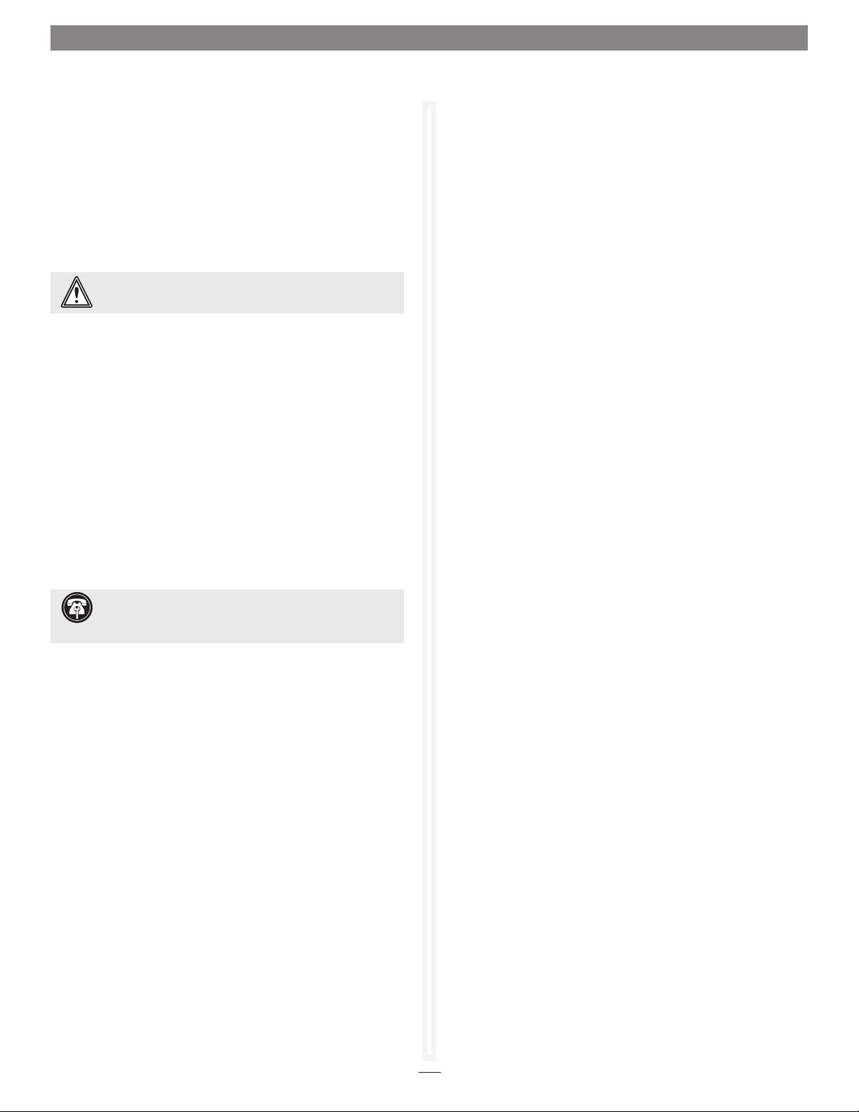
• The Basic Info tab displays PCI information for the selected
channel. See Figure 7 on page 6.
• The current status of the Configuration Tool is represented in
the Status pane at the bottom of the window.
About window
The About window, displayed when About is selected from the
Help menu, lists the ATTO Configuration Tool’s version number.
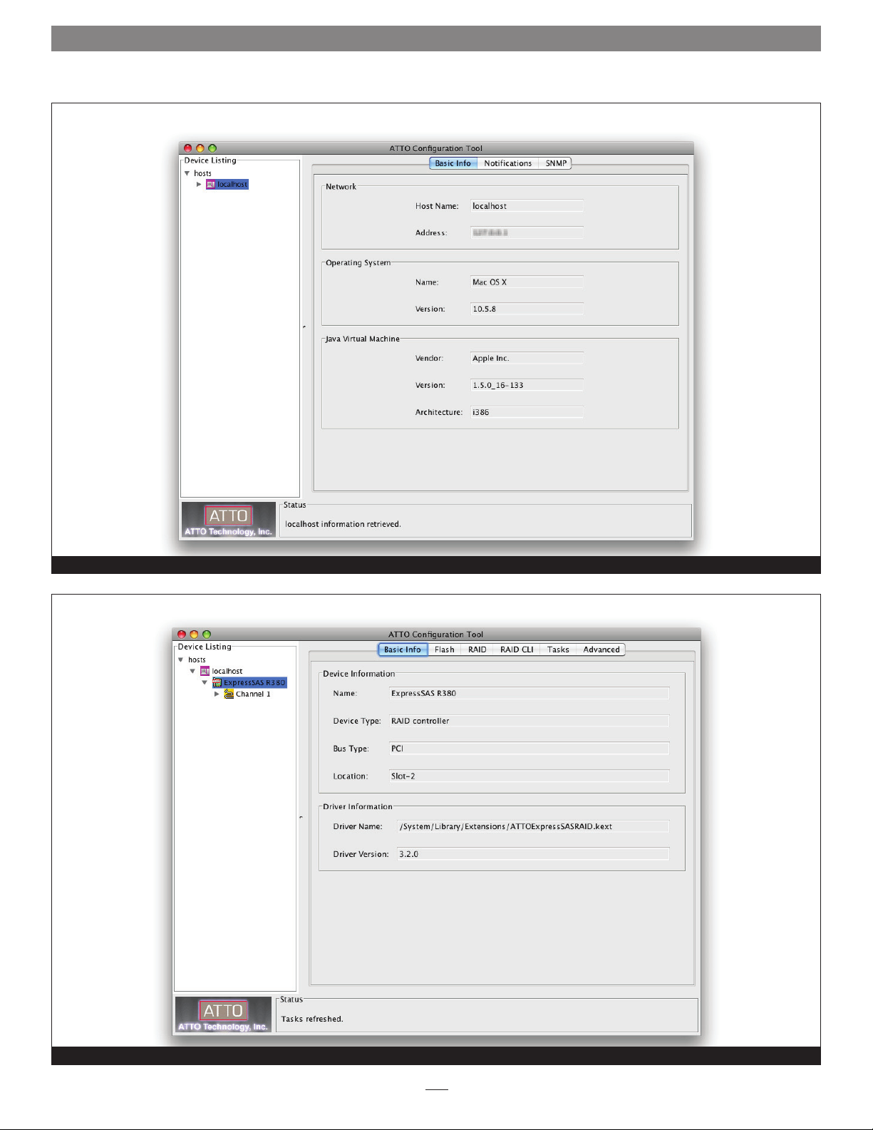
• The Flash tab provides information about the current flash
version programmed on the highlighted controller. See Figure 3
on page 4.
Click the Browse button at the bottom of the tab
to search for new flash files on your system such as
FlashBundle_2007_02_27.R380. Once you’ve selected the flash
file, click the Update button to automatically update your
Sonnet RAID controller.
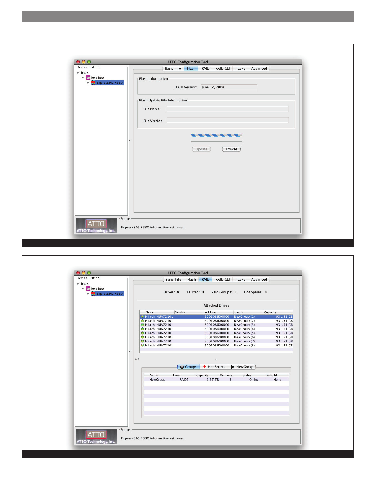
• The RAID tab provides information about attached drives,
their RAID group and Hot Spare associations, and their
operating status. With the RAID tab selected, you can create,
modify, and delete RAID groups. You may also schedule or
start diagnostic and maintenance procedures, start individual
drive performance testing, and send commands to attached
enclosures to identify drives. See Figure 4 on page 4.
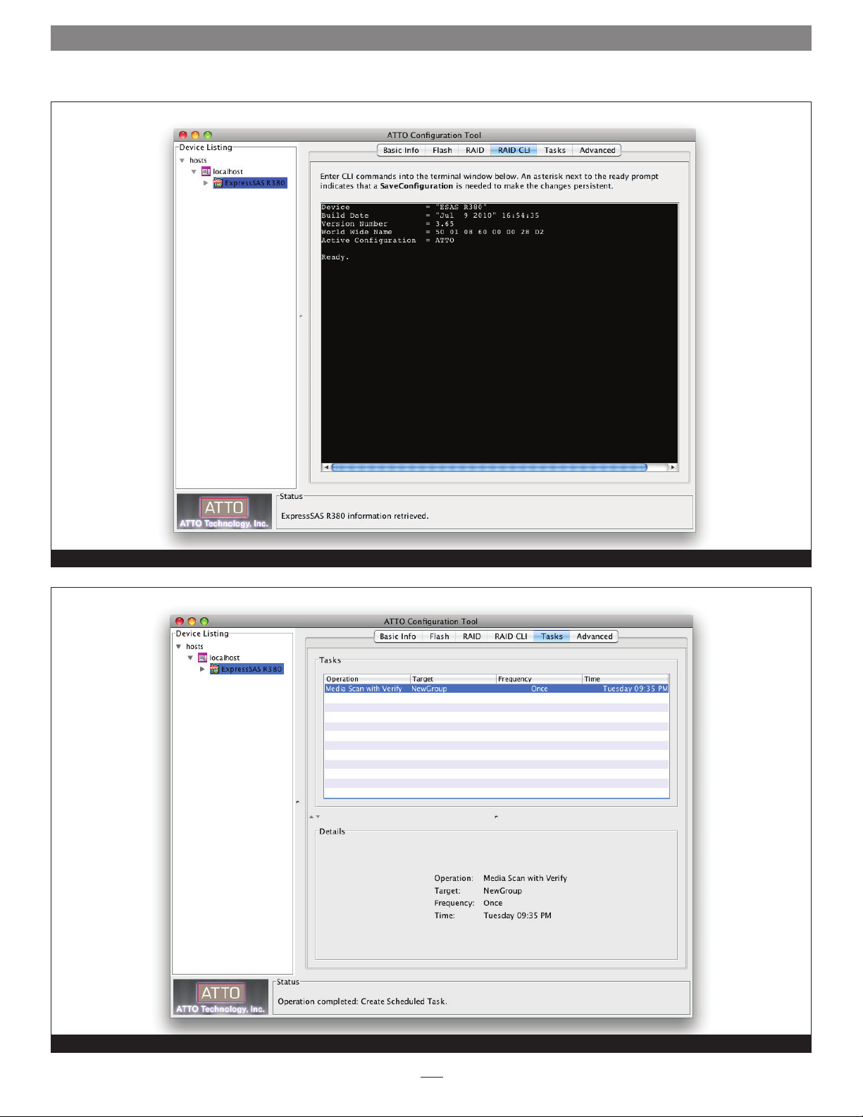
• The RAID CLI tab provides access to the command line
interface, which, as an alternative to application menu-based
commands, enables the use of ASCII-based commands to
control configuration and diagnostic tasks. See Figure 5 on
page 5.
Support Note: The following feature does not work with
Fusion D400RAID, Fusion D800RAID, nor Fusion R800RAID
storage systems.
Select a Device
The following tabs display in the right pane when you select a
specific device in the Device Listing pane:
• The Basic Info tab displays information about the selected
enclosure or SAS expander.
• The Flash tab does not function with the Fusion storage
systems; clicking this tab merely displays a message.
Support Note: The SES tab appears only when an
enclosure with one or two SAS expanders, such as Fusion
DX800RAID, or Fusion RX1600RAID, is used.
• The SES tab displays SES (SCSI Enclosure Services) status
information for SES devices such as power supplies and fans.
See Figure 8 on page 6.
2
Page 9
1.0 ATTO Configuration Tool Overview
Basic Info displayed when Local Host chosen in the Device Listing pane
Figure 1
Basic Info displayed when the Sonnet RAID controller is chosen in the Device Listing pane
Figure 2
3
Page 10
1.0 ATTO Configuration Tool Overview
Flash information displayed when the Sonnet RAID controller is chosen in the Device Listing pane
Figure 3
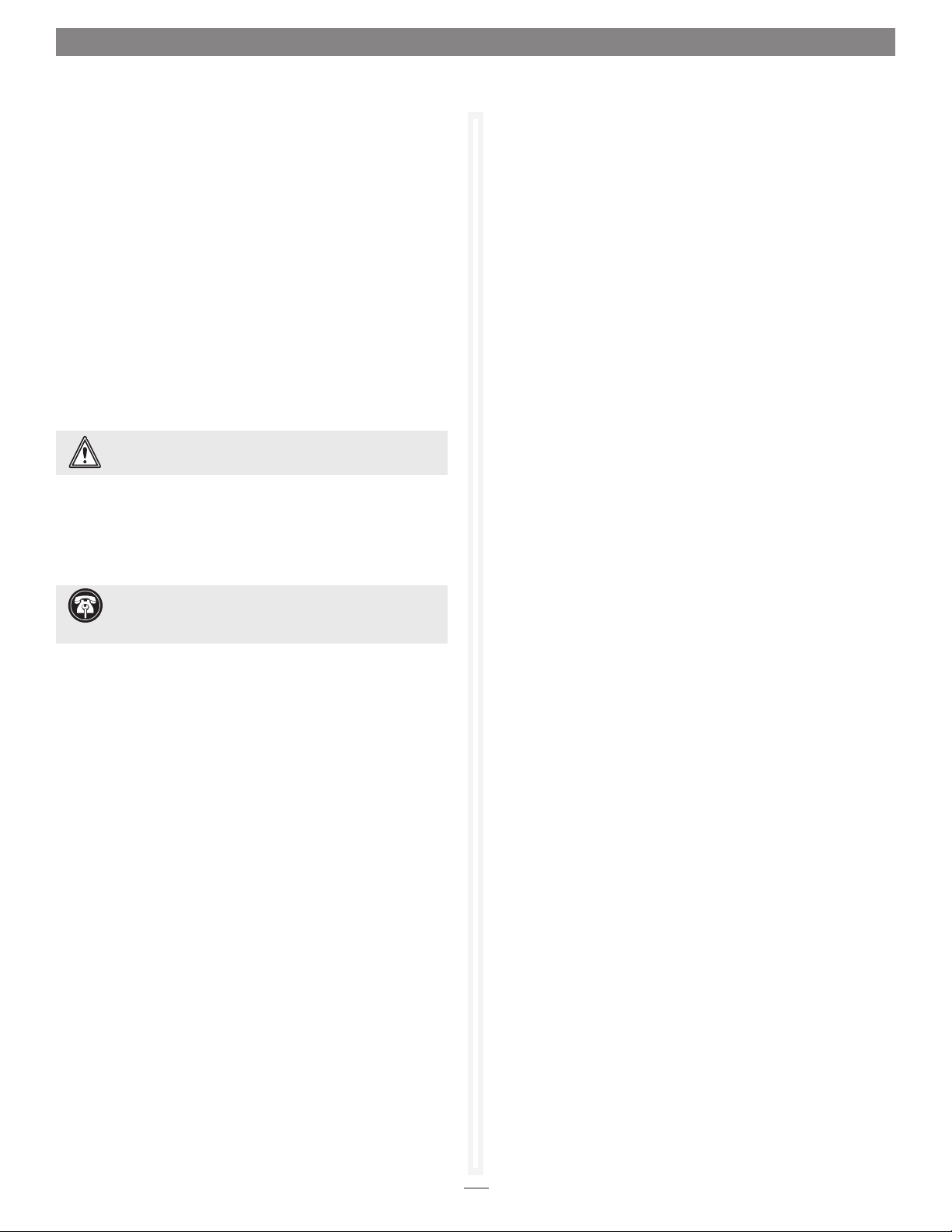
RAID group and associated drive information displayed when the Sonnet RAID controller is chosen in the Device Listing pane
Figure 4
4
Page 11
1.0 ATTO Configuration Tool Overview
RAID CLI displayed when the Sonnet RAID controller is chosen in the Device Listing pane
Figure 5
Scheduled tasks information displayed when the Sonnet RAID controller is chosen in the Device Listing pane
Figure 6
5
Page 12
1.0 ATTO Configuration Tool Overview
Basic Info displayed when a SAS expander is selected in the Device Listing pane
Figure 7
SES information displayed when a SAS expander is selected in the Device Listing pane
Figure 8
6
Page 13
1.1 RAID Controller NVRAM Settings
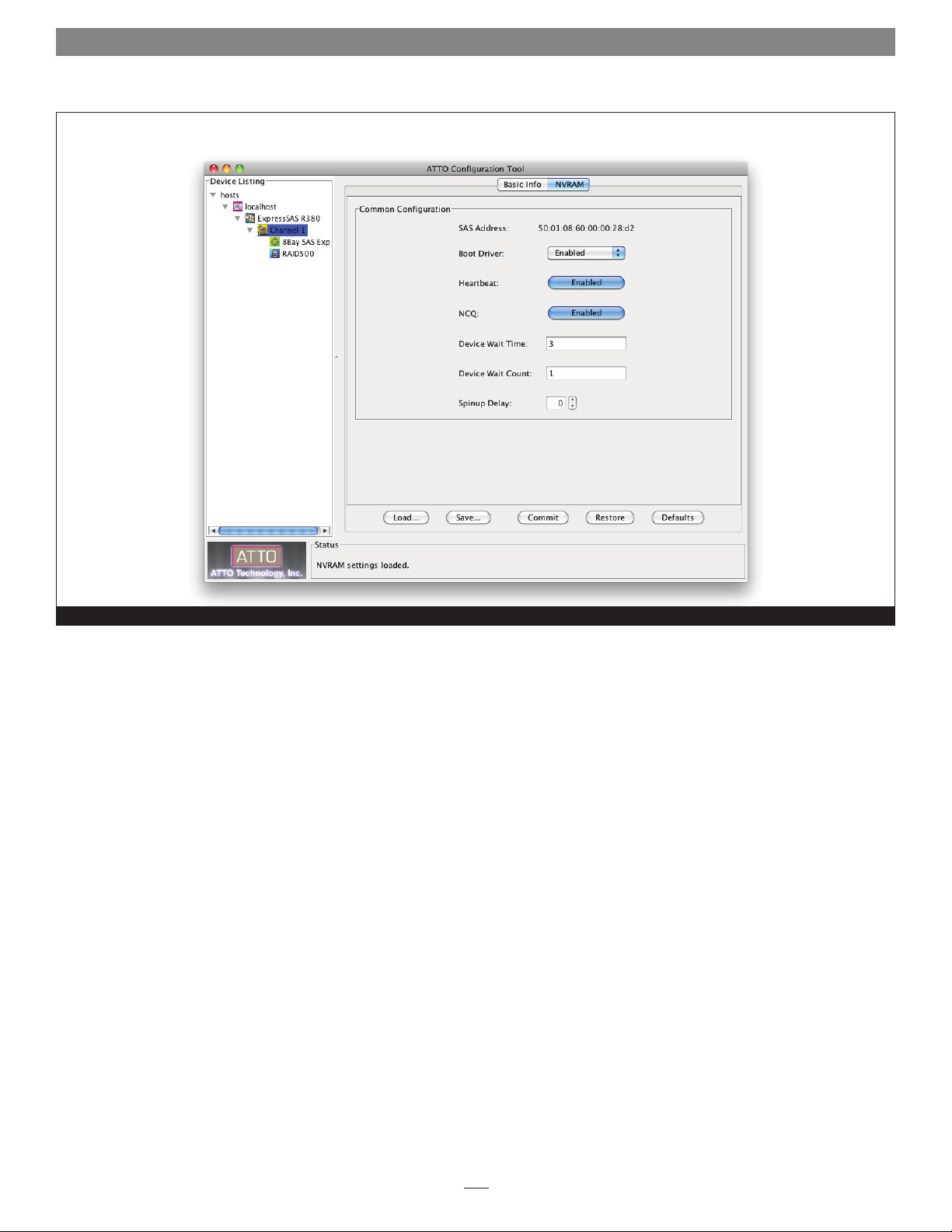
The settings in the NVRAM tab vary depending upon the RAID
controller and operating system.
Sonnet’s RAID controllers are designed to operate properly using
factory settings. Entering invalid or incorrect settings when using
an NVRAM configuration utility such as the ATTO Configuration
Tool may cause your controller to function incorrectly.
See Figure 9 on page 8 for an example of the NVRAM pane.
WARNING: Back up system data when installing or
changing hardware configurations.
Use caution when making changes to NVRAM settings and only
make changes to those with which you are familiar. Once you
have made the desired changes, click Commit to save the changes.
Click Save to name and save an NVRAM configuration. Click Load
to load a saved NVRAM configuration. Changes do not take effect
until you reboot the system.
If you do not want to make any changes, you may choose one of
the following:
• Defaults: restores the controller to factory default settings. The
Commit button must be clicked to save any changes.
• Restore: reverts to the NVRAM settings saved the last time the
Commit button was used. Clicking Commit is not necessary.
Support Note: The SAS address is a globally-unique
identifier assigned to devices such as the Sonnet RAID
controller, and is similar to an Ethernet adapter’s MAC address.
SAS Address
Read only
NCQ (Native Command Queueing)
Choices: enabled, scan only, disabled
Default: disabled
When enabled, the Sonnet RAID controller’s driver sends
multiple simultaneous commands to NCQ-capable SATA disk
drives. Enabling NCQ may be useful when the Fusion storage system
is used in database applications, but may hinder performance in video
editing and other applications.
Device Wait Time
Choices: 1–255 seconds
Default: 3
Specifies the number of seconds that the driver waits for devices
to appear.
Device Wait Count
Choices: 1–255 devices
Default: 1
Specifies the number of devices that must appear in order to cancel
the Device Wait Time period.
Spinup Delay
Choices: 0-20 seconds
Default: 0
Specifies the number of seconds each SAS port waits for disk drives
to spin up.
Multiplexing (6 Gb/s RAID Controller Only)
Choices: enabled, disabled
Default: disabled
Displays the SAS address assigned to the controller. The value
cannot be modified.
Boot Driver
Choices: disabled, enabled, scan only
Default: disabled
If enabled and disk drives are detected during the bus scan, the
BIOS driver remains resident. If disabled, the BIOS starts, resets
the controller chip and unloads the driver.
If Scan Only is selected, the BIOS driver scans the bus and displays
the devices attached, then unloads itself after a brief delay.
Heartbeat
Choices: enabled, disabled
Default: enabled
When enabled, the Sonnet RAID controller’s firmware is required
to respond to periodic activity. If the firmware does not respond,
the system driver resets the firmware on the controller.
When enabled, multiplexing enables multiple 3 Gb/s devices to
aggregate 6 Gb/s SAS bandwidth. In order to utilize this feature,
devices must support multiplexing and conform to SAS 2.0
compliancy.
Phy Speed (6 Gb/s RAID Controller Only)
Choices: 6 Gb/s, 3 Gb/s, 1.5 Gb/s
Default: auto
Enables the user to manually adjust the PHY.
7
Page 14
1.1 RAID Controller NVRAM Settings
NVRAM settings information shown when a Fusion drive enclosure is selected in the Device Listing pane
Figure 9
8
Page 15
1.2 RAID Group Setup and Management
Support Note: In Fusion RAID storage systems
shipped from Sonnet with hard drives installed, the
drives are formatted Mac OS Extended (Journaled),
configured as a single RAID 5 or RAID 6 RAID group, and
ready for use with Mac OS X-based systems. If you need to
change the configuration, delete the existing RAID group (see
RAID Group Deletion on page 13), and use the Configuration
Tool and the operating system software tools to reformat
and reconfigure the drives. See page xiv for Drive Reformat
Instructions for Mac OS and Windows users.
The ATTO Configuration Tool enables you to configure disk storage
into RAID groups or Hot Spare drives.
Note: Even an individual JBOD disk is considered to be a RAID group.
Use the ATTO Configuration Tool to set up RAID groups on your
Sonnet RAID controller in one of the following RAID levels:
• JBOD
• RAID Level 0
• RAID Level 1
• RAID Level 4
• RAID Level 5
• RAID Level 6
• RAID Level 10
• DVRAID™
Support Note: DVRAID is a customized, protected
RAID 4 configuration. It is optimized for increased digital
video playback performance when compared to that obtained
from a RAID 5 configuration. DVRAID’s write per formance is
decreased in order to accomplish this optimization.
DVRAID RAID groups may be set up automatically by the ATTO
Configuration Tool. All other RAID configurations require
customized input; Sonnet recommends Custom RAID group
setup.
Each RAID group may be divided into one or more partitions;
each partition appears to the your computer as a virtual disk.
Preliminary Configuration Steps
1. Launch the ATTO Configuration Tool application.
2. The Configuration Tool main screen appears. In the Device
Listing pane on the left side of the window, click ExpressSAS
Rxxx under localhost; a new set of tabs appears in the right
pane. See Figure 10 on page 14 for an overview.
3. Click the RAID tab; the application scans for drives.
Attached drives are displayed in the top pane, while RAID
groups and Hot Spares are displayed in the bottom pane.
Support Note: In the ATTO Configuration Tool’s Device
Listing pane, the Sonnet R AID controller is identified as
an ExpressSAS Rxxx.
Custom RAID Group Setup Steps
1. After completing Preliminary Configuration Steps, select
RAID Management > Create Group > Customized from the
application menu.
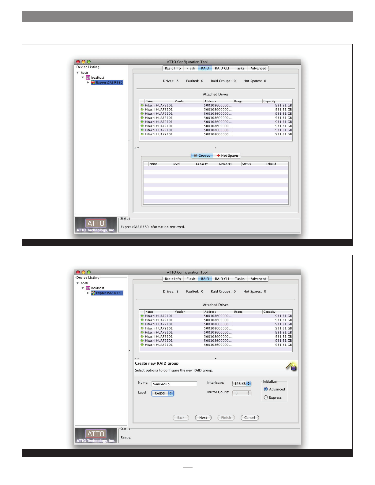
2. Select the first set of options to configure the new RAID
group. See Figure 11 on page 14.
• Name: name the RAID group or use the one assigned by the
Configuration Tool. The name must be unique, contain no
spaces, and contain no more than 14 characters.
Support Note: Two RAID groups with the same name
may not be recognized. If you add another RAID group to
your setup, you must make sure it does not have the same name
as the existing one, and change it if it does.
• Level: select a RAID group level from the drop-down menu.
Support Note: Descriptions of RAID levels can be found
on the Wikipedia.org Web site at the following addresses:
http://en.wikipedia.org/wiki/Standard_R AID_levels and
http://en.wikipedia.org/wiki/ Nested_RAID_levels.
Windows Support Note: In order to create RAID
volumes larger than 2TB under Windows, you must do one
of the following: Select the 4KB sector size when creating a
custom RAID group (not DVRAID) and select Simple Volume
as the formatting option in the Disk Management application.
-OR- Use the software configuration tools included with the
Fusion storage to create volumes up to 2TB, span (link together
in a virtual chain) the volumes, and then format as NTFS. - ORUse GPT formatting. Note that drives and volumes with GPT
formatting are not visible to the 32-bit version of Windows XP
Professional, nor to the 32-bit version of Windows Server 2003 SP1.
You may use the command line interface pane from the RAID
CLI tab in the ATTO Configuration Tool to set up or modify
various parameters (Refer to Appendix A). However, using the
menu-based procedures listed in this chapter is the preferred
method for setting up RAID configurations for the Fusion
storage system.
• Interleave: select an interleave value. The default value
is 64KB or 128KB, depending on the OS used. Sonnet
recommends 1MB interleave size for maximum video
editing performance.
Support Note: The interleave value chosen when
creating a RAID group makes a significant impact on
performance. Fusion R AID storage systems shipped from Sonnet
with pre-installed hard disk drives are now optimized for use
with video editing (larger files) applications, typically with an
interleave value of 512KB or 1MB selected. If you intend to
use your storage system primarily for storage of smaller files
(database, office documents, etc.), choose a smaller interleave
value of 64KB or 128KB.
• Mirror Count: select the number of mirror groups when
RAID 1 or RAID 10 RAID groups are created.
9
Page 16
1.2 RAID Group Setup and Management
Custom RAID Group Setup Steps (continued)
• Initialize: select Advanced or Express; Sonnet recommends
choosing Advanced (which is the default).
Support Note: When the Advanced Initialize option is
selected, parity blocks are calculated and the RAID group
is thoroughly scanned and subjected to a complete Write/ Verify
operation to map out any bad blocks on the drives before the
RAID group is made available for use.
When the Express Initialize option is chosen, drives are not
scanned and subjected to the Write/Verify operation, but parity
blocks are calculated and the RAID group may be used during
the initialization.
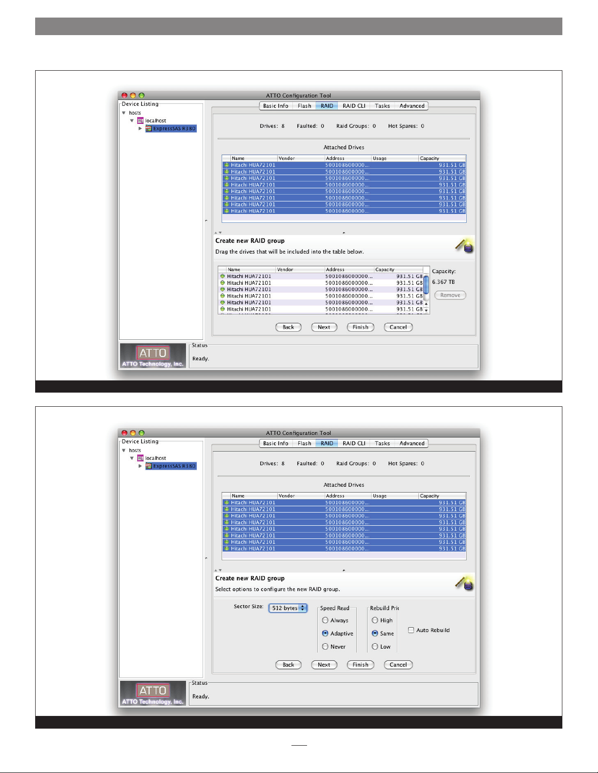
3. Click Next. Select the drives in the top pane and drag them
into the device area in the bottom pane. See Figure 12 on
page 15.
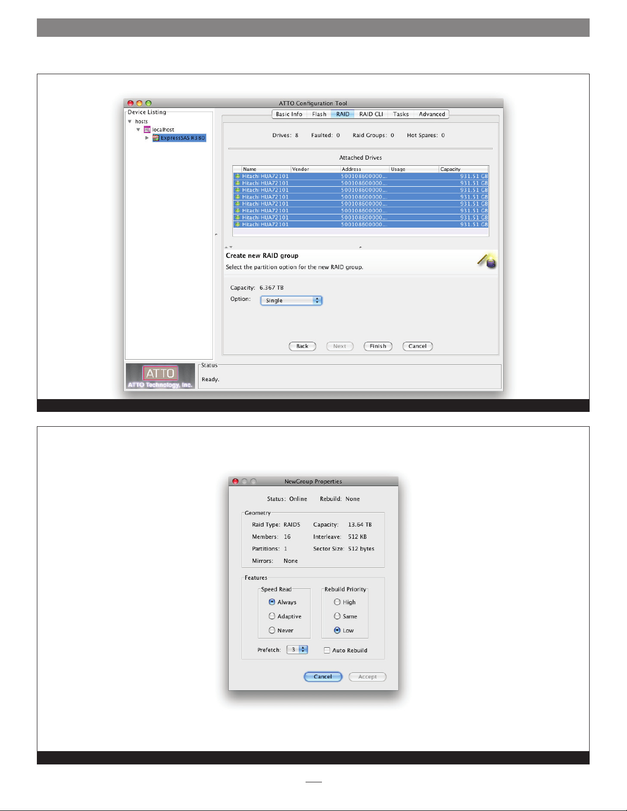
4. Click Next. Select the next set of options to configure the
new RAID group. See Figure 13 on page 15.
• Sector Size: select a sector size from the drop down box.
The default is 512 bytes. Use 512 bytes unless you need to
use the MBR partition scheme under Windows.
Windows Support Note: Choosing the 4K sector size
enables the creation and use of R AID volumes up to 16TB
on systems running Windows XP 32-bit. Otherwise, the volumes
are limited to 2TB.
5. If you want the RAID group to be presented as one virtual
disk (partition), click Finish. If you want more than one
virtual disk (partition), click Next (see Figure 14 on page 16),
and then select one of the following options:
• leave as a single partition
• partition by count
• partition by size
If you choose to split the RAID group by count or capacity,
you must enter additional information.
6. If you have not already done so, click Finish.
7. A confirmation dialog box asks you to approve the settings
you have chosen. Click Yes.
8. Select the RAID group in the Groups pane.
9. Select RAID Management > Properties from the application
menu. In the Properties window, change the Prefetch value
to 6. See Figure 15 on page 16.
10. Click accept.
11. Click the RAID CLI tab, type “get raidcommandtimeout”
and then hit the return key; if the number that appears is
60000, skip to step 13.
• Speed Read: select Always, Adaptive, or Never. The default
is Adaptive, but Sonnet recommends Always.
Support Note: For the Speed Read option, select Always
if you expect to work with large sequential files (video, for
example), Never if you expect most of the files to be smaller in
size (general storage, database, etc.), or Adaptive if you expect
mixed use or don’t know.
• Rebuild Priority: select High, Same, or Low. The default is
Same.
Support Note: Rebuild priority affects the performance
of your Fusion storage system when a drive is replaced and
a degraded RAID group is rebuilt. Selecting Low rebuild priority
enables you to continue working at the best performance level
possible, but the RAID group will take much longer to rebuild.
• Auto Rebuild: on or off.
Support Note: If the Auto Rebuild option is not checked,
you will have to manually start a RAID group rebuild after
replacing a faulted drive.
12. Type “set raidcommandtimeout 60000” and then hit the
return key.
13. Every RAID group must finish initializing, and be formatted
by your computer’s operating system software before it becomes
available for use; Mac users will use Disk Utility, Windows
users will use Disk Management. For more information on
drive formatting, see Mac OS Drive Formatting or Windows
Drive Formatting starting on page 11.
10
Page 17
1.2 RAID Group Setup and Management
Hot Spares Setup and Usage
If a drive in a parity RAID group becomes degraded or faulted,
the RAID group will lose some redundancy until a new member
(drive) is rebuilt into it. You can automate this procedure by
designating one or more drives as Hot Spares. You may set up a
pool of Hot Spare drives of different sizes appropriate for your
RAID groups.
Support Note: Hard drives in the Hot Spare pool should
be of appropriate capacity to the RAID group so that
smaller drives are not replaced by much larger Hot Spare drives.
If the Sonnet RAID controller detects a faulted drive in a RAID
group with a designated Hot Spare:
• The controller searches the Hot Spare pool for the smallest drive
of sufficient capacity to substitute for the faulted drive.
• The faulted drive is replaced with one from the Hot Spare pool.
• The controller begins an automatic rebuild of the RAID group.
Select RAID Management > New Hot Spare (or Delete Hot Spare)
from the application menu, and then follow the instructions on
the screen.
Mac OS Drive Formatting
1. Depending on how you configure your setup, a Disk Insertion
window stating that there is an unreadable volume will
appear at some point during the RAID group creation process;
click Initialize, and then Disk Utility will open.
2. In the Disk Utility window, each RAID group you created
using the ATTO Configuration Tool will appear as a single
volume. Select the volume, and then click the Erase tab at the
top of the window.
Support Note for Power Mac G5 Users: When
creating RAID groups 16TB or larger, uncheck the Install
Mac OS 9 Drivers checkbox; OS 9 drivers do not support volumes
greater than 16TB.
Windows 7/Server 2008/Vista Drive Formatting
1. Click Start, then right-click Computer and select Manage.
2. In the Computer Management window, click Storage in the
left pane to expand the list (if necessary), and then click Disk
Management.
3. When the Initialize Disk window appears, select the RAID
volume you created. Select the GPT partition style unless you
need to access your RAID storage from a computer running
32-bit Windows XP Professional or 32-bit Windows Server
2003. Click OK.
4. In the Disk Management window, each RAID group you
created will appear (listed as “unallocated”) as a single volume.
Right-click where the word “unallocated” appears, and then
select New Simple Volume.
5. When the Welcome to the New Simple Volume Wizard window
appears, click Next to start the process.
6. When the New Simple Volume Wizard window appears, click
Next.
7. When the Specify Volume Size window appears, click Next if
you want all of the Fusion system’s capacity to remain as one
block (volume). Otherwise, adjust the volume size to meet
your needs, and then click Next.
8. When the Assign Drive Letter or Path window appears, select
Assign the following drive letter, choose a letter, and then
click Next.
9. When the Format Partition window appears, enter a new
name for the volume table if you’d like. For RAID volumes
up to 16TB, accept the default allocation unit size; for RAID
volumes greater than 16TB, select 8192 from the drop-down
menu. Select Perform a quick format, and then click Next.
Note: If you do not select the quick format option, this process will take
much longer to complete.
3. Click the Erase button; a window will appear asking you to
approve your choice; click Erase.
4. Repeat steps 2 and 3 for each remaining unformatted RAID
group, and then close Disk Utility.
5. Depending on how you configured the RAID groups, the
volumes may already be mounted and present on the desktop.
If you created a DVRAID, RAID 4, RAID 5, or RAID 6 RAID
group, configuration will take much longer. You may check
on the progress by double-clicking the volume name in the
lower pane of the ATTO Configuration Tool window.
6. Once all the RAID groups have been formatted and finish
building, they are ready to use.
10. When the next window appears, click Finish.
11. Repeat steps 4–10 for each remaining “unallocated” disk.
12. Depending on how you configured the RAID groups, the
volumes may already be available to the system. If you
created a DVRAID, RAID 4, RAID 5, or RAID 6 RAID group,
configuration will take much longer. You may check on the
progress by double-clicking the volume name in the lower
pane of the ATTO Configuration Tool window.
13. Once all the RAID groups have been formatted and finish
building, they are ready to use.
11
Page 18
1.2 RAID Group Setup and Management
Windows XP/Server 2003 Drive Formatting
1. Select Start > Control Panel from the Windows Start menu. In
the Control Panel window, double-click Administrative Tools.
In the Administrative Tools window, double-click Computer
Management.
2. In the Computer Management window, click Storage on the
left, and then click Disk Management beneath it.
3. When the Initialize and Convert Disk Wizard window appears,
click Cancel.
4. In the Disk Management window, each RAID group you
created will appear (listed as “unallocated”) as a single volume.
Right-click one volume where the words “Not Initialized”
appear, and then select Initialize Disk.
5. When the Initialize Disk window appears, select the RAID
volume(s), and then click OK.
6. Back in the Disk Management window, right-click where the
word “Online” appears, and then select Convert to GPT Disk.
7. Right-click where the word “unallocated” appears, and then
select New Partition.
8. When the New Partition Wizard window appears, click Next.
15. Depending on how you configured the RAID groups,
the volumes may already be available to use. If you
created a DVRAID, RAID Level 4, or RAID Level 5 group,
configuration will take much longer. You may check on the
progress by double-clicking the RAID group name in the
lower pane of the ATTO Configuration Tool window.
16. Once all the RAID groups have been formatted and finish
building, they are ready to use.
RAID Group Management Overview
The ATTO Configuration Tool interface may be used to manage
the replacement of a failed drive, add capacity to a RAID group,
change a RAID group’s current RAID level configuration to a new
one, and change a RAID group’s properties.
WARNING: Data can be compromised or lost when
deleting storage or rearranging storage configurations.
The ATTO Configuration Tool interface guides you step by step
through many procedures which allow you to modify your
storage and RAID configurations. Read all support notes and
warnings carefully as you go to ensure the best performance
and use of your storage. Many of these procedures may only be
performed on drives that are not currently part of a RAID group,
are not designated as a Hot Spare, or were offline when you
initially set up RAID configurations.
9. When the Select Partition Type window appears, select Primary
Partition, and then click Next.
10. When the Specify Partition Size window appears, click Next if
you want all of the Fusion system’s capacity to remain as one
block (volume). Otherwise, adjust the volume size to meet
your needs, and then click Next.
11. When the Assign Drive Letter or Path window appears, choose
a letter, and then click Next.
12. When the Format Partition window appears, enter a new
name for the volume if you’d like. For RAID volumes up to
16TB, accept the default allocation unit size; for RAID volumes
greater than 16TB, select 8192 from the drop-down menu.
Select Perform a quick format, and then click Next.
Note: If you do not select the quick format option, this process will take
much longer to complete.
13. When the next window appears, click Finish.
14. Repeat steps 4–13 for each remaining “unallocated” disk.
Support Note: An unallocated drive or unallocated
storage is storage which is not part of a RAID group, not
designated as a Hot Spare or was offline when you initially set up
a RAID configuration using the ATTO Configuration Tool interface.
RAID Group Capacity Expansion
Select RAID Management > Expand Capacity from the
application menu, and then follow the onscreen instructions.
Depending on the RAID configuration, you may need to add more
than one drive at a time.
Mac User’s Support Note: Although this feature is
supported by the ATTO utility, as of this writing, Mac
OS X does not support RAID group capacity expansion.
WARNING: Adding drives to an existing RAID group may
adversely impact performance. You cannot reverse this
operation unless you delete the R AID group.
12
Page 19
1.2 RAID Group Setup and Management
RAID Group RAID Level Migration
Changing a RAID group from one RAID level to another is called
migration. The following migration levels are supported:
• JBOD to RAID Level 0
• JBOD to RAID Level 1
• RAID Level 0 to RAID Level 10
• RAID Level 1 to RAID 10
Select RAID Management > Migrate RAID Level from the
application menu, and then follow the instructions on the screen.
RAID Group Deletion
You may delete a group using the ATTO Configuration Tool.
Select RAID Management > Delete Group from the application
menu, and then follow the instructions on the screen.
WARNING: Data can be compromised or lost when
deleting storage or rearranging storage configurations.
RAID Group Rebuilding
If a RAID group becomes compromised, you must rebuild it.
Select RAID Management > Rebuild Group from the application
menu, and then follow the instructions on the screen.
Support Note: A RAID group rebuild may take several
hours to complete, depending on the operating system,
drive capacities, and RAID configuration.
You may pause a RAID group rebuild by selecting the RAID
group in the lower pane, and then selecting RAID Management >
Pause Rebuild from the application menu. To resume the rebuild,
select the RAID group in the bottom pane, and then select RAID
Management > Resume Rebuild from the application menu.
RAID Group Properties Modification
Each RAID group has specific properties, and the value of each
property remains with the RAID group when it is moved from
one computer to another. Some of the properties can only be
specified during RAID group creation (RAID level, interleave, and
sector size), whereas others may be changed at any time during
the life of the RAID group. See Figure 15 on page 16.
2. Select RAID Management > Properties from the application
menu, and then view or change the current properties:
• Speed Read specifies the cache policy to be used during
read operations. Once a read command is given, the
ExpressSAS RAID code retrieves the next set of sequential
data from the RAID group’s drives and caches it in the
Sonnet RAID controller’s internal memory. If you select
Never, read caching is never performed. If you select
Always, read caching is always performed. If you select
Adaptive, Speed Read is enabled or disabled depending on
the sequential patterns detected in I/O requests.
• Auto Rebuild controls the replacement of a faulted
drive with any available unallocated drive. When you
click the Auto Rebuild check box and the Accept button,
Auto Rebuild is enabled. If a drive becomes faulted, the
ExpressSAS RAID adapter replaces the drive with an
unallocated drive.
• Rebuild Priority specifies the ratio of rebuild I/O activity
to host I/O activity. A rebuild priority of Same (default
value) indicates that rebuild I/O and host I/O are treated
equally. A rebuild priority of Low indicates that host I/O is
given a higher priority than rebuild I/O. A rebuild priority
of High indicates that rebuild I/O is given a higher priority
than host I/O. In practical terms, selecting Low enables
you to continue working with full read performance, but
the rebuild will take much more time to complete.
• Prefetch specifies the number of stripes that are read when
Speed Read is enabled or set to adaptive. The valid values
for prefetch are 0, 1, 2, 3, 4, 5 and 6; the default value is 1.
This property can only be changed after the RAID group is
created. To access this property, select the RAID group and
view its properties.
3. Click Accept.
1. Select a RAID group in the Groups pane.
13
Page 20
1.2 RAID Group Setup and Management
Configuration Tool main screen with the RAID tab selected
Figure 10
Options selection screen displayed when creating new, custom RAID groups
Figure 11
14
Page 21
1.2 RAID Group Setup and Management
Drives selected to create a new RAID group
Figure 12
Additional options selection screen displayed when creating new, custom RAID groups
Figure 13
15
Page 22
1.2 RAID Group Setup and Management
Select the number of partitions for the new RAID group
Select the RAID group’s properties
Figure 14
Figure 15
16
Page 23

1.3 Drive and RAID Group Monitoring
The ATTO Configuration Tool provides useful information on
individual drives and associated RAID groups.
Use the ATTO Configuration Tool to gather basic or detailed
information about the drives connected to the Sonnet RAID
controller, and operational status on the RAID groups created
with them.
Basic Drive Information
Open the ATTO Configuration Tool, expand the device tree in the
Device Listing pane until ExpressSAS Rxxx appears, and then click
to highlight it. In the Attached Drives pane, general information
for all the drives is displayed. See Figure 16 on page 20.
• LED icon: Indicates operational status of the drives. Green =
online, red = faulted
• Name: Displays the drive’s model number
• Vendor: Not used
• Address: Displays the SAS address generated by the Sonnet
RAID controller
• Usage: Identifies how the drive is being used. If it is part of
a RAID group, the group name and member number are
displayed. If it is a Hot Spare, it is listed as a Hot Spare.
• Capacity: Displays the drive’s formatted capacity.
Detailed Drive Information
In the Attached Drives pane, double-click a drive name to view
detailed information. See Figure 17 on page 20.
• Index: Displays the drive’s RAID group index number. This
number is used in CLI commands
• Capacity: Displays the drive’s formatted capacity
• Usage: Identifies how the drive is being used. If it is part of
a RAID group, the group name and member number are
displayed. If it is a Hot Spare, it is listed as a Hot Spare.
• Sector Size: Displays the drive’s sector size
RAID Group Information
In the bottom pane, click the Groups tab to display RAID groups.
See Figure 16 on page 19.
• Name: Displays the name of the RAID group
• Level: Indicates the RAID level formatting for the RAID group
• Capacity: Indicates the formatted, configured capacity of the
RAID group
• Members: Indicates the number of drives in the RAID group
• Status: Displays the operating status for the RAID group. Refer
to Definitions on page 35 for detailed information.
• Rebuild: Specifies the general condition of the RAID group.
None indicates no rebuild is taking place, nor is it necessary;
Rebuilding indicates that the RAID group is degraded, and is
in the process of rebuilding; Paused indicates that a rebuild
was interrupted and needs to be restarted to finish. Refer to
Definitions on page 35 for detailed information.
• Status: Displays the drive’s operating status. OK is displayed if it
is functioning normally. If there is a problem, Faulted or Error is
displayed.
• Type: Displays the type of media
• Name: Displays the drive’s model number
• Vendor: Not used; always displays Not Available
• Serial: Displays the drive’s serial number
• Address: Displays the SAS address generated by the Sonnet
RAID controller
• Speed: Displays the drive’s interface speed
• Revision: Displays the drive’s firmware revision
• LUN: Displays the logical unit number, which is the number
assigned to drive’s RAID group
Drive Identification
You may identify one or more drives using the ATTO
Configuration Tool to turn on LEDs in the Fusion drive
enclosure.
1. Launch the ATTO Configuration Tool application.
2. Expand the device tree to highlight the ExpressSAS Rxxx,
and then click the RAID tab. Status for all drives connected
to the Sonnet RAID controller will be displayed.
3. Click on one or more drives individually that you want to
identify in the Attached Drives list.
4. Select RAID Management > Locate > Drive from the
application menu. If the drive does not support this method
of identification, a message will appear in the bottom pane;
go to the next step. Otherwise, look at the Fusion enclosure;
the drive activity LED(s) for the specific drive(s) will be lit
until you deselect Locate in the application menu.
(continued)
17
Page 24

1.3 Drive and RAID Group Monitoring
Drive Identification (continued)
5. Double-click a drive in the top pane to display detailed
information, and note the index number for the drive. Close
the detailed drive information window.
6. Click the RAID CLI tab, and then type “Blockdevidentify x”,
where x is the index number. Look at the Fusion enclosure;
the drive activity LED for the specific drive will be lit.
Note: Type “Blockdevidstop” to turn off the LED.
S.M.A.R.T. Data
Self-Monitoring, Analysis and Reporting Technology, or
S.M.A.R.T., is a monitoring system built into SATA drives to detect
and report on various indicators of drive health. The S.M.A.R.T.
feature keeps track of and reports on the status of SATA
drive health using certain parameters recorded by the drives.
Notifications can be sent when certain pre-determined values are
exceeded.
Use the ATTO Configuration Tool to view the files that record
changes to an individual drive’s S.M.A.R.T. parameters. The files
are permanent and can be viewed independently whether you
have enabled monitoring or not.
S.M.A.R.T. Monitoring Enabling and Disabling
Monitoring is disabled by default; if you want to use the feature,
you must enable it. You may enable or disable the monitoring
feature at any time.
1. Launch the ATTO Configuration Tool application.
3. The S.M.A.R.T. Status box displays.
If there has been a change from a previous S.M.A.R.T. status
record, an arrow indicates the change direction, either higher or
lower. See Figure 18 on page 21.
The S.M.A.R.T. status display also contains information such as
the date and time the S.M.A.R.T. status was recorded, the total
number of records for this drive, and the current monitoring
status (enabled or disabled).
You may move to previous or subsequent records, query the drive
or refresh the view using controls on the interface. Control-click
(or right-click) a single drive in the Attached Drives pane, and
select S.M.A.R.T. Status from the sub-menu to view the record.
• Use the left arrow or right arrow control to move between
S.M.A.R.T. status records.
• Use the Refresh button to query the drive for the latest values.
If any values are different from the most recent record, a new
record is created and displayed.
S.M.A.R.T. Attribute Filtering
Each of the S.M.A.R.T. status attributes is assigned one or more
classification types:
• performance
• error rate
• event count
• critical
2. Expand the device tree and select the ExpressSAS Rxxx, and
then click the RAID tab.
3. Select RAID Management > Monitor S.M.A.R.T. from the
application menu to enable (indicated with a check mark) or
disable monitoring.
S.M.A.R.T. Status Checking
The ATTO Configuration Tool interface displays the latest
S.M.A.R.T. status record for a selected drive. All attributes reported
by the drive are listed with each attribute’s Threshold, Worst,
Current and Raw value; the threshold value is the value at which
notification of a problem is generated by the software.
1. Select a single drive in the Attached Drives pane.
2. Control-click or right-click on the selected drive, and then
select S.M.A.R.T. Status in the sub-menu.
The S.M.A.R.T. Status dialog box can be filtered to display any
combination of these types. The default view is to display all types.
1. Open the S.M.A.R.T. Status box, and then control-click (or
right-click) in the table area where the attribute values are
displayed.
2. Each classification type that is visible has a check mark.
Select any classification type to change the check mark.
18
Page 25

1.3 Drive and RAID Group Monitoring
S.M.A.R.T. Notifications
When S.M.A.R.T. monitoring is enabled, status is collected from
each SATA drive at 60 minute intervals. If the data is different
than the previous status, a S.M.A.R.T. status record is added to the
S.M.A.R.T. status file for that drive. A notification of the S.M.A.R.T.
status difference is generated based upon the current settings
in the Notifications pane. Refer to RAID Event Notifications on
page 25.
The S.M.A.R.T. status’ notification level is determined as follows:
• INFO: None of the status values was below the threshold value.
• WARNING: One or more of the status values was below a
threshold value but none was classified as critical.
• CRITICAL: One or more of the status values was below a
threshold value and one was classified critical.
19
Page 26

1.3 Drive and RAID Group Monitoring
Drive information displayed with the RAID tab selected
Detailed information displayed for a specific drive
Figure 16
Figure 17
20
Page 27

1.3 Drive and RAID Group Monitoring
S.M.A.R.T. status displayed for a specific drive
Figure 18
21
Page 28

22
Page 29

1.4 Enclosure (SES) Health Monitoring
Support Note: This feature does not work with Fusion
D400RAID, Fusion D800RAID, nor Fusion R800RAID
storage systems.
Many Fusion drive enclosures contain a SCSI enclosure processor
which tracks enclosure health status, drive identification and drive
fault identification. The ATTO Configuration Tool recognizes drive
enclosures that provide SCSI Enclosure Services (SES).
Use the ATTO Configuration Tool to gather the health status of
the enclosure’s power supplies and fans. If the status of either of
these sub-systems indicates a failure, the controller reports the
problem. The Configuration Tool shows the status of selected SES
devices and reports the specific health of each sub-system.
SES Status Checking
1. Select the Fusion drive enclosure from the Device Listing
tree in the Configuration Tool. See Figure 19 on page 24.
2. Select the SES tab at the top of the right pane.
3. View the overall status of each component across the top of
the right pane. See Figure 20 on page 24.
Note: Depending on the Fusion storage system used, some features may
not be fully supported.
4. Select a specific sub-system (power supply or fans) and view
the status of the reporting sub-system.
23
Page 30

1.4 Enclosure (SES) Health Monitoring
Basic info information displayed when a SAS expander is selected
Figure 19
Power supply status displayed when the SES (SCSI Enclosure Services) tab is selected
Figure 20
24
Page 31

1.5 RAID Event Notifications
The ATTO Configuration Tool may be configured to issue notifications
via audible and visual alerts when a RAID event occurs.
RAID events are divided into three categories:
• Critical events are ones in which a serious problem has
occurred and the administrator of the RAID group should
perform corrective action.
• Warning events are less serious but still warrant recording and
notification at some level.
• Information alerts provide supportive information about
warnings or critical events.
Drop-down boxes on the Notifications pane allow you to choose
the type of event which prompts an alert. See Figure 21 on
page 26.
• Critical: only Critical events are reported
• Warning: all Warnings and Critical events are reported
• All: all Critical, Warning and Information events are reported
• None: no event is reported. The None level is useful in email
notification because you can set up email addresses to which
alerts might be sent at some future time.
You can choose any combination of notifications on the
Notification pane as needed. The notifications are specified at
the host system level and apply to all Sonnet RAID controllers
installed in the host system.
Logging
Logging notification records the type of event as text in a log file
you specify.
• The ATTO Configuration Tool provides a default location
for event log files which you can change in the Location
field found under Logging on the Notifications tab. The log
file name is a combination of the adapter’s SAS address, an
underscore and a 0 or 1.
• You may limit the size of the log file by entering a number
greater than 0 in the Size Limit (KB) field. Once the limit is
reached, another log file is created. Once that log file’s limit is
reached, the Configuration Tool overwrites the first log file and
continues to rotate between the two files.
• If you do not want to limit the storage capability of the log file,
enter a zero in the field.
• Choose the type of event you want recorded in the event log
from the Events: drop down box.
Email Alerts
Email notification sends a message to designated email addresses
when the event level from the drop down box next to the
Notification Address: field is reached.
• You may specify several notification addresses on each line in
the email section of the Notifications pane, each separated by
commas, for any event level.
• You must complete the IP address or name of the server and
sender.
Basic Alerts
You can select an audible alert, a visual alert, or both for a
particular category of events. Select a notification level using the
drop-down box next to the Audible and Visual labels on the
Notifications screen.
Audible alert uses either the Sonnet RAID controller’s onboard
buzzer (R6xx) or the computer’s speaker (R3xx) to sound an
alarm. The alarm continuously sounds until you stop it. There is
an icon in the system tray or the menu bar that is used to turn
off the alarm. You must right-click (or option-click)the icon and
then select Mute Audible Alert from the menu; this will stop the
alarm.
Visual alert uses a system modal pop-up to display a message.
You must close the pop-up using the pop-up’s button.
Support Note: Audible and visual alerts are not available
on systems running Linux.
• You may specify a user name and password for the mail server
if one is required.
• A critical event email notification is sent after a 10-second
delay to allow several related events to be reported in the same
message. All other notification emails are sent at 15-minute
intervals.
• You may specify if you are using a TLS/SSL enabled server (e.g.
Note: Contact your email provider for the appropriate Port Number.
25
™
Gmail
, Yahoo®, etc.) as well as the port used on that TLS/
SSL server. Enabling SSL enables you to connect to these email
providers, as they usually require secure connections. Leave this
box unchecked if you are using a server that doesn’t require a
secure connection.
Choices: Enable SSL control = checked, unchecked, Port
number control = 1–65535
Default values: Enable SSL control = unchecked, Port number
control = 25
Using any other number will result in email notification failure.
Page 32

1.5 RAID Event Notifications
Configuration Tool Notifications screen when the local host is selected in the Device Listing pane
Figure 21
26
Page 33

1.6 RAID Group Media Maintenance
The Media Scan feature scans disk drives for media errors and parity
errors. All media errors are counted and fixed. All parity errors are
reported in the event log. The two options are described below.
Use the ATTO Configuration Tool to check and repair media
errors on parity RAID groups. You may start the media scan
operations manually, or schedule the operations for a later time,
or on a weekly basis.
Media Scan Options
Media Scan works with parity RAID group members, Hot Spare
drives and unallocated drives. Media Scan reads the selected
drives and, if a media error is found, Media Scan re-writes the
disk with the media error. The drive will relocate the bad sector’s
data to an alternate part of the drive. Media Scan rewrites the
correct data for a disk that is a member of an online parity
RAID group. Media Scan writes random data to Hot Spare drives
and unallocated drives. The Media Scan feature records the
number of media errors detected and corrected for each drive.
These counts are stored persistently if the drive is a RAID group
member or a Hot Spare drive. The counts are not persistently
stored for any other drives.
Media Scan with Parity Verify is a variation of Media Scan that
is available for online parity RAID groups only. Parity Verification is
performed on each RAID group stripe that has no detected media
errors. The parity of the stripe is recalculated and compared to
the original parity for the stripe. If there is a mismatch, an error is
generated and recorded in the Event Log and System Log files.
Support Note: Media Scan operations significantly
impact your Fusion storage system’s performance, and
may take several hours to complete. We suggest that you schedule
Media Scan operations for times when the system in not in use.
Start a Media Scan
1. If your computer is running Mac OS X, drag the RAID group
you want to scan to the trash (changes to an eject icon) to
eject it. Otherwise, skip to step 2.
2. Select the RAID group, Hot Spare drive(s), or unallocated
drive(s) you want to scan in the Groups pane; one RAID
group, or multiple Hot Spare or unallocated drives may be
selected.
3. Control-click (or right-click) the RAID group and select Scan
Only or Parity Verify (Media Scan + Parity Verify) from
the drop menu. See Figure 22 on page 29. You may also
select RAID Management > Scanning > Scan Only (or RAID
Management > Scanning > Parity Verify) from the application
menu.
4. The scan starts immediately; the Attached Drives pane
displays a rotating icon next to each drive being scanned,
and the RAID Group pane displays the type of scan being
performed and a status for percent complete.
Schedule a Media Scan
1. Select a RAID group in the Groups pane.
Note: Your computer must be on in order to perform manual or
scheduled Media Scan operations.
Modes of operation for:
• Online RAID Group – Media Scan performs SCSI Read
commands on each stripe group. Parity verification is
performed on a stripe that has no media errors. Media Scan
activity is scheduled in accordance with the Rebuild Priority
Level. Media Scan is restarted after reboot if the Media Scan did
not complete.
• Degraded or Offline RAID Group – Media Scan performs SCSI
Read commands for each stripe group of the online drives. No
parity verification occurs. The Media Scan is restarted after a
reboot if the Media Scan did not complete.
• Hot Spares & Unallocated Drives – Media Scan performs SCSI
Read commands for each selected drive. Media Scan is not
restarted after a reboot if the Media Scan did not complete.
2. Control-click (or right-click) the RAID group and select
Schedule. See Figure 23 on page 30. You may also select RAID
Management > Schedule from the application menu.
3. Select Scan Only or Parity Verify, and then click Next. See
Figure 24 on page 30.
4. Select the time and frequency schedule for the task to be
performed. See Figure 25 on page 31.
5. Click Finish, and then click Yes in the next dialog box to
finish scheduling the task.
Note: You may schedule only one task per RAID group. You may not
schedule media scans for Hot Spare drives or unallocated drives.
27
Page 34

1.6 RAID Group Media Maintenance
Cancel, Pause, or Resume a Media Scan
Media Scan functions for a parity RAID group may be paused,
resumed and cancelled. The Configuration Tool provides menu
items to pause and resume, and CLI provides a command to
cancel the Media Scan. The results of the Media Scan up to the
time of the pause or cancel are saved persistently.
Media Scan functions for Hot Spare and unallocated drives can
be cancelled, but cannot be paused. Media Scan of Hot Plug
and unallocated drives are run immediately and they are not
scheduled. The Configuration Tool provides menu items to start
and cancel Media Scan functions on these drives.
1. Select the RAID group being scanned in the groups pane.
2. Control-click (or right-click) the RAID group and select
Pause Media (or Parity) Scan to pause the Media Scan, or
Cancel to stop the Media Scan. You may also select RAID
Management > Pause Media (or Parity) Scan, or RAID
Management > Cancel from the application menu.
Note: You may resume a paused Media Scan operation by control-
clicking (or right-clicking) the RAID group that was being
scanned and selecting Resume Media Scan, or by selecting RAID
Management > Resume from the application menu.
Manage Scheduled Media Scans
1. Click the Tasks tab.
2. Select the RAID group scheduled for a Media Scan.
3. Control-click (or right-click) the RAID group and select
Reschedule to change the Media Scan schedule, or
Delete to delete the Media Scan. You may also select Task
Management > Reschedule, or Task Management > Delete
from the application menu. See Figure 26 on page 31.
Automatic Media Scan Cancellation
A Media Scan may be automatically cancelled for the following
reasons:
• A parity RAID group being scanned requires a rebuild operation
View a Scan Report
1. Select the Sonnet RAID controller from the Device Listing
pane.
2. Select the RAID tab in the right pane.
3. Select the RAID group, Hot Spare drive(s) or unallocated
drive(s) whose scan report should be displayed. One RAID
group can be selected or multiple Hot Spare and unallocated
drives can be selected.
4. Select RAID Management > Scan Report from the application
menu.
5. A Media Scan Error Report message box appears with the
scan results. See Figure 27 on page 31. If a scan is currently
in process, the Scanned column indicates the percent
complete for the operation.
The Scan Report includes the counts for the most recent scan and
the total results for all Media Scan operations. This information
is persistent for RAID group drives and Hot Spare drives since
it is stored in the drive’s metadata. The results may be erased
from the drive when the metadata is rewritten, e.g. a Hot Spare’s
information is lost when the Hot Spare is added to a RAID group.
The Media Scan results for an unallocated drive are only available
until a reboot occurs.
Media Scan provides the following metrics:
• Media errors detected on most recent scan in the Errors
column.
• Media errors corrected on most recent scan.
• Total stripe groups scanned on most recent scan. This data is
not displayed in Configuration Tool.
• Media errors detected on all scans in the Total Errors column.
• Media errors corrected on all scans.
• A parity RAID group is being scanned and the last drive is
marked “Faulted”
• A Hot Spare being scanned is needed for a RAID group rebuild
• An unallocated drive being scanned is needed for a RAID group
rebuild
A Media Scan is not cancelled in the following scenario:
• An unallocated drive cannot be added to a RAID group when a
Media Scan is active on the drive.
The Media Scan must be manually cancelled in the above
scenario.
• Total number of all scans in the Scans column.
The Media Scan Error Report does not display the count of
corrected errors. The corrected error count is displayed while the
mouse pointer hovers over the Errors or Total Errors value for a
specific drive. If the detected errors do not equal the corrected
errors the warning icon appears to the left of device name
column.
The Scan Report is updated by the Configuration Tool every 10
seconds. The metrics are not updated when the Media Scan is
paused.
28
Page 35

1.6 RAID Group Media Maintenance
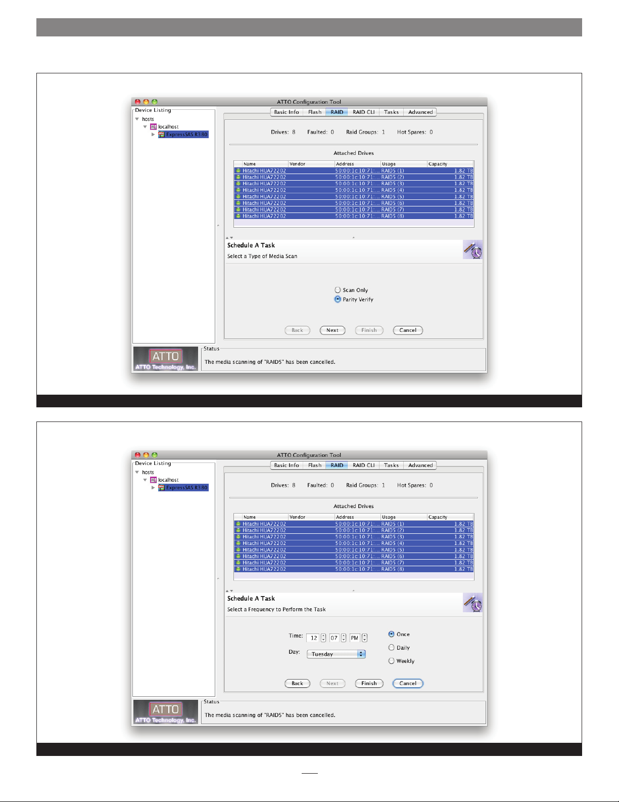
Selecting the Scan Only media scan operation for a RAID group
Scheduling a Media Scan operation for a RAID group
Figure 22
Figure 23
29
Page 36
1.6 RAID Group Media Maintenance
Selecting the Media Scan type
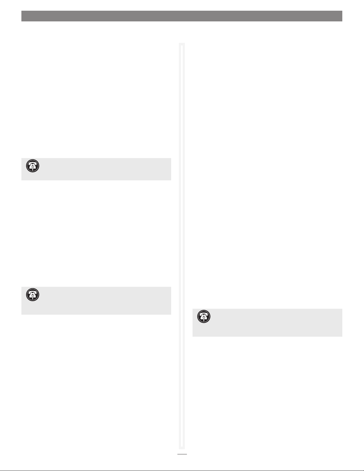
Scheduling the time and frequency for a Media Scan operation
Figure 24
Figure 25
30
Page 37

1.6 RAID Group Media Maintenance
Changing a scheduled Media Scan operation
Viewing a RAID group’s Media Scan report
Figure 26
Figure 27
31
Page 38

32
Page 39
1.7 Identify and Replace a Faulted Drive
If a drive in a RAID group fails, the RAID group’s status becomes
degraded. This section will help you to identify and replace the bad
drive.
Automatic Faulted Drive Identification
On supported Fusion storage systems, drive fault identification
is performed automatically by the Sonnet RAID controller
when a RAID group member becomes degraded by exhibiting
unrecoverable errors during I/O. The RAID controller reports
the status of the drive and asks the Fusion enclosure to perform
fault identification, illuminating a blinking red LED as a result.
The fault identification continues until the drive is replaced or
the RAID group is deleted. The ATTO Configuration Tool will
also issue visual, audible, and email notifications (only when
configured to do so).
Support Note: Automatic faulted drive identification
does not work with Fusion D400RAID, Fusion D800RAID,
nor Fusion R800RAID storage systems.
Manual Faulted Drive Identification
When an error occurs that requires a drive to be replaced, the
ATTO Configuration Tool will issue visual, audible, and email
notifications (only when configured to do so).
6. Click the RAID CLI tab, and then type “Blockdevidentify x”,
where x is the index number. Look at the Fusion enclosure;
the drive activity LED for the specific drive will be lit.
Note: Type “Blockdevidstop” to turn off the LED.
Faulted Drive Replacement with Auto Rebuild
A faulted drive is automatically replaced if Auto Rebuild is
enabled and a suitable unallocated disk is available. Suitable
unallocated drives are initialized, have a large enough capacity to
replace the degraded drive, and cannot contain any RAID group
information. The unallocated drive may be a pre-existing drive or
a newly-installed drive.
If a Hot Spare Pool exists, the Sonnet RAID controller chooses a
suitable Hot Spare drive before selecting an unallocated drive.
Manual Faulted Drive Replacement
Once you have identified the faulted drive, you must replace it
and rebuild the affected RAID group.
1. Swap out the faulted drive.
2. Launch the ATTO Configuration Tool application.
After a drive failure notification has appeared,
1. Launch the ATTO Configuration Tool application.
2. Expand the device tree to show the ExpressSAS Rxxx, and
then click the RAID tab. Drive status for all drives connected
to the Sonnet RAID controller will be displayed. The faulted
or degraded drive will have a red LED icon next to it.
Support Note: If you have configured your setup to
include a Hot Spare drive, the ATTO Configuration Tool
will automatically start rebuilding the RAID group using the Hot
Spare drive.
3. Click on the faulted or degraded drive you want to identify
in the Attached Drives list.
4. Select RAID Management > Locate > Drive from the
application menu. If the drive is not supported for this
method of identification, a message will appear in the
bottom pane; go to the next step. Otherwise, look at the
Fusion enclosure; the drive activity LED for the specific drive
will be lit until you deselect Locate.
5. Double-click the faulted or degraded drive in the top pane to
display detailed information, and note the index number for
the drive. Close the detailed drive information window.
3. Expand the device tree to show the ExpressSAS Rxxx, and
then click to highlight the degraded RAID group.
4. Select RAID Management > Rebuild from the application
menu; a tab for the RAID group will open, and you will
be prompted to drag a free drive on top of the one being
replaced. See Figure 28 on page 34.
5. After starting the rebuild, you may use the RAID group, but
its write performance will be reduced until the rebuild is
complete.
Support Note: A RAID group rebuild will take several
hours to complete, the total time depending on the rebuild
priority, drive capacities, RAID group configuration, and operating
system used.
33
Page 40

1.7 Identify and Replace a Faulted Drive
Replacing a faulted drive with an unallocated drive to rebuild a degraded RAID group
Figure 28
34
Page 41
1.8 Recover Data from Offline RAID Groups
Sonnet RAID controllers use ATTO Technologies’ DriveAssure™
technology to maintain error-free operation of RAID group
member drives. This includes features like Drive Initialization,
Media Scan, Parity Verify, Performance Monitoring, and
algorithms for latency and response management. Occasionally,
a drive will suffer a mechanical or fatal media error that makes
it unusable. A connection error may cause multiple drives to be
inaccessible, resulting in an array that cannot be accessed normally.
This chapter describes procedures to follow that may allow data
to be partially recovered when drives fail or become inaccessible
and cause a RAID group to go offline.
WARNING: Anytime a R AID group goes offline, its
data integrity has been compromised. It is imperative
that data consistency checks and/or file system repair tools be
used to validate recovered data.
Definitions
RAID Group Status Definition
ONLINE The RAID group state is online, with all RAID group members available and fully operational.
DEGRADED The RAID group does not have full data protection. This occurs when a non-critical number of RAID
group members (drives) are unavailable, degraded or faulted (i.e., one member in a RAID 5 RAID
group, two in a RAID 6 RAID group, and so forth). On a read command to inaccessible drive(s), the
data is derived using redundancy or parity. A degraded RAID group may be initializing or rebuilding.
OFFLINE The RAID group’s data cannot be accessed because a critical number or drives have been faulted or
removed. For example, two or more drives in a RAID 5 RAID group have failed.
RECOVERY The RAID group is in basic data recovery mode. I/O may be limited to reads while in this state.
REC EXT The RAID group is in extreme data recovery mode, which returns data at all costs. I/O may be
limited to reads while in this state.
RAID Member Status Values Definition
ONLINE The drive is fully operational
DEGRADED Some of the drive’s data is not up to date
UNAVAILABLE Connection to the drive has been lost
FAULTED The drive has an unrecoverable error
Rebuild Status Values Definition
OK Data is up to date
REBLD The rebuild operation is in progress
A_INIT The advanced initialization operation is in progress
X_INIT The express initialization operation is in progress
MSCAN The media scan operation is in progress
Rebuild Status Suffixes Definition
…FAULTED The operation ceased due to an error
…HALTED The operation was stopped at the user request
…INTRUPTD The operation was interrupted
…% COMPL Percent completion for operation
35
Page 42

1.8 Recover Data from Offline RAID Groups
RAID Group Failure Scenarios
RAID groups cannot be accessed normally when their member
disks fail, and the RAID group is marked offline. RAID groups of
different RAID levels are marked offline for different reasons, as
follows:
RAID Level Reason(s) for Being Marked OFFLINE Recovery Method
JBOD and RAID 1 Any drive failure See Recovery from Faults on Critical Number of Drives on
page 38
Error during rebuild See Recovery from Failed Rebuild on page 37
RAID 1 and RAID 10
RAID 4 and RAID 5
RAID 6
Mistaken replacement of a good drive when its
mirror has failed
Errors on two or more drives See Recovery from Faults on Critical Number of Drives on
Error during rebuild See Recovery from Failed Rebuild on page 37
Mistaken replacement of a good drive when
another member of the RAID group has failed
Errors on three or more drives See Recovery from Faults on Critical Number of Drives on
Error during rebuild See Recovery from Failed Rebuild on page 37
Mistaken replacement of good drive(s) when
another member of the RAID group has failed
See Recovery from Replacement of the Wrong Drive on page 39
page 38
See Recovery from Replacement of the Wrong Drive on page 39
page 38
See Recovery from Replacement of the Wrong Drive on page 39
Drive Replacement on a Failure Condition
Replace RAID Group Member Drives as Soon as They Fail
With parity and redundancy RAID levels, a RAID group can
withstand the loss of one member, and the data is still valid and
accessible. In this case, the RAID group goes into degraded mode
and uses parity or redundancy to generate the data. Although the
RAID group is fully operational, it is at risk because if any other
drive fails, data integrity is called into question.
A Warning About Drive Replacement
A very common reason that an array goes from degraded mode
to offline mode is when the wrong drive is replaced. By pulling
out a perfectly good drive, a double-drive fault occurs and there
are insufficient drives to generate data. The following procedure
is very important when you are considering removing a failed
drive, to ensure the correct drive is pulled.
Identifying Failed Drives
Prior to replacing a drive, you must be very sure which one
failed. If a failed drive is in an enclosure that supports SES (Fusion
DX800RAID, RX1600RAID, RX1600 Expansion), the drive
module's fault LED should be blinking. In that case, it is clear
which drive should be replaced. If multiple drive modules’ LEDs
are blinking, power cycling the enclosure(s) and reseating the
drives can sometimes correct intermittent conditions.
Recovery Mode
Sometimes, despite careful operation and maintenance, drives
will coincidentally fail in such a way that the RAID group
integrity is compromised. After a RAID group has been marked
offline because of problems with member drives, there is a way to
possibly recover some of the data. The guidelines and commands
listed on the following pages of this chapter can help recover data
from an offline RAID group. The following descriptions refer to
RAID 5 specifically, but the principles also extend to other RAID
types.
The ATTO Configuration Tool provides other methods to
identify failed drives. Please refer to Identify and Replace a Faulted
Drive on page 33 for details.
36
Page 43

1.8 Recover Data from Offline RAID Groups
Recovery from a Failed Rebuild
Occasionally during a RAID group rebuild, one of the drives
that was not replaced encounters a media error, which causes
the rebuild to stop and forces the group offline. The following
diagrams illustrate a scenario where the failed drive is removed
and replaced. You may force the rebuild to continue. The error
recovery procedure is also valid if there is a Hot Spare, or if there
is an unallocated drive and Auto Rebuild is enabled.
A functioning RAID 5 RAID group:
321 4
encounters a drive failure, forcing the RAID group into a
degraded state:
321 4
The failed drive is either replaced with a Hot Spare or
unallocated drive, or is removed and replaced:
Barring major problems, the RAID group will be put back
online at the end of the rebuild recovery. However, at the
location corresponding to the media error, the data may be invalid!
Anytime a RAID group goes offline, data integrity has been
compromised! It is imperative that data consistency checks
and file system repair tools are used to validate the data before
trying to use it. See File System Repair Tools on page 39 for more
information.
Recovery from a Failed Rebuild with a Second
Unrecoverable Drive Failure
If a rebuild cannot continue to completion because of
unrecoverable errors on multiple drives, use the Extreme recovery
mode, described below, to try to recover data.
A functioning RAID 5 RAID group:
321 4
encounters a drive failure, forcing the RAID group into a
degraded state:
321 4A
If a media error is encountered during the rebuild process, the
rebuild is halted and the RAID group is forced offline:
321 4A
Use the ATTO Configuration Tool to force the RAID group to
continue the rebuild. First, display the RAID group information.
See Figure 29 on page 43. Then right-click the offline RAID
group that has the rebuild status rebuilding (faulted). Select the
Start Recovery Rebuild option. See Figure 30 on page 43.
The RAID group status will change from offline to degraded. The
rebuild status will change from rebuilding (faulted) to recovery
rebuilding (n%), where n% is the completion percentage of the
rebuild process.
Once the rebuild completes, the RAID group goes online:
321 4
The failed drive is either replaced with a Hot Spare or
unallocated drive, or is removed and replaced:
321 4A
If another drive fails with an unrecoverable failure during the
rebuild process, the rebuild is halted and RAID group is forced
offline:
321 4A
Choose the Extreme Recovery option to try to recover data from
all drives.
321 4A 4
321 4A
(continued)
37
Page 44
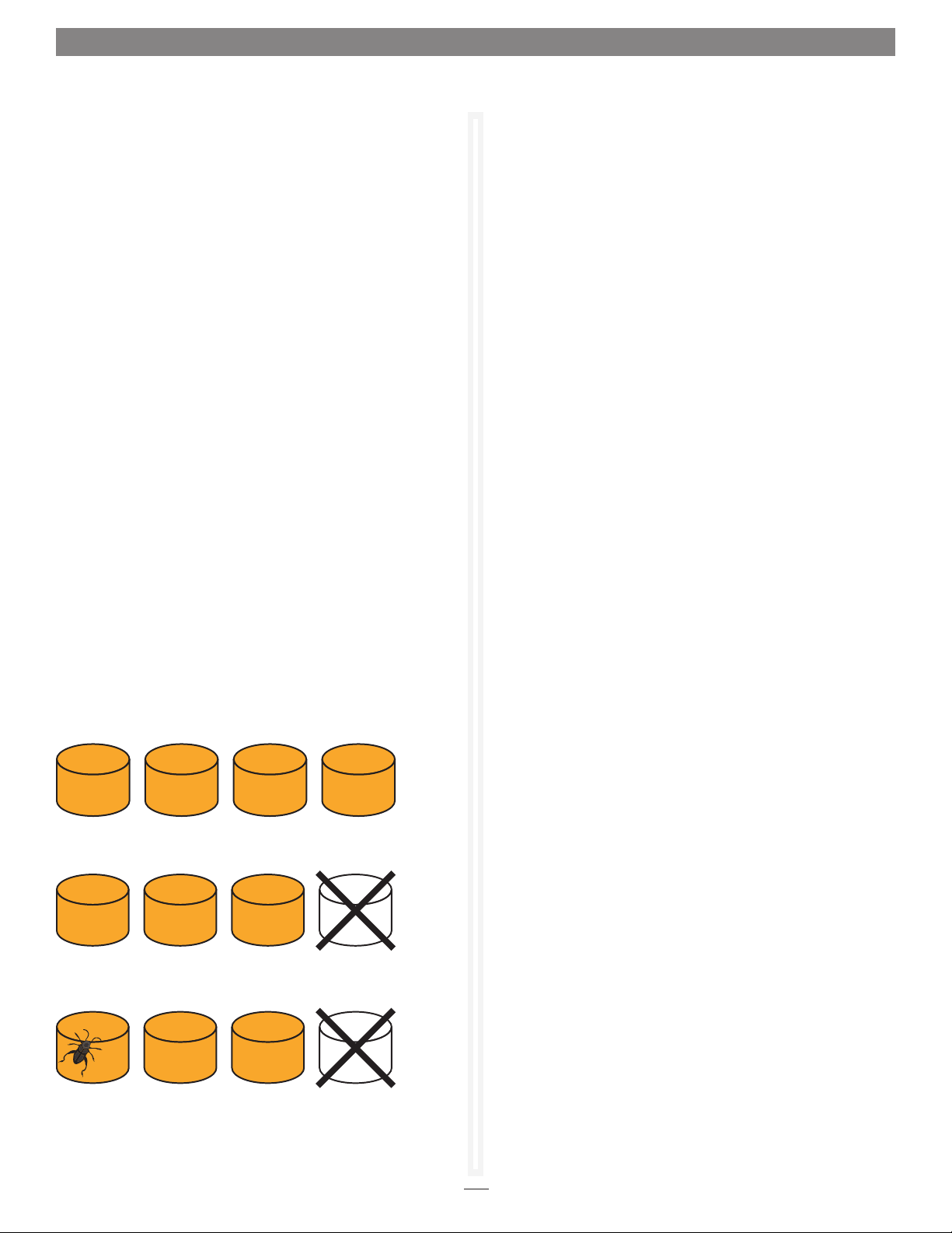
1.8 Recover Data from Offline RAID Groups
Recovery from a Failed Rebuild with a Second
Unrecoverable Drive Failure (continued)
When a serious disk failure occurs during a rebuild, the rebuild
cannot be forced to continue, but the Extreme recovery mode
may be viable. If there is an available slot, reinstall the original
failed drive (the drive provides another possible source of data
even if the data is stale). This original failed drive will only be
accessed if there is an error on one of the other RAID group
members. Note that in this failure scenario, data may be
extensively compromised.
Extreme recovery mode is only accessible from the Command
Line Interface. Use the CLI command RGRecover Extreme to
enter the “extreme, read-at- all-costs” recovery mode. See Using
the CLI to Enable/Disable Recovery mode on page 41. Use a host
application to read whatever data it can off of the drives and back
it up to another location. The RAID group will stay in recovery
mode. If you use the CLI command RGRecover Disable to disable
this mode, the RAID group will return to the offline state. There
is no mechanism to put this RAID group back online. Once you
have the data backed up, use only good drives to create a new
RAID group, and then restore the data to the new RAID group.
Recovery from Faults on a Critical Number of Drives
In this scenario, there is no Hot Spare drive, and either Auto
Rebuild is not enabled or there is no spare drive for Auto Rebuild
to use. When the first drive fails, the array will continue to
operate in DEGRADED mode and return data when requested.
However, once another error occurs, the group is forced offline
and data has been compromised. Basic recovery mode should be
used.
A functioning RAID 5 RAID group:
321 4
Basic Recovery Mode
Use the ATTO Configuration Tool or CLI commands to put the
compromised RAID group into basic recovery mode. This allows
you to read data to a backup location, replace all failed or marginal
drives, and then restore the data to the new drives. However, at
the location corresponding to the media error, the data may be
invalid! Anytime a RAID group goes offline, data integrity has
been compromised. It is crucial that data consistency checks and file
system repair tools are used to validate the data.
To enter recovery mode from the ATTO Configuration Tool,
select and right-click (or control-click) the offline RAID group to
get display menu options and select the Basic Rebuild option. See
Figure 31 on page 44.
The RAID group status will change from offline to recovery
(basic). Once you enter recovery mode, use a host application
to read whatever data it can off of the drives and back it up to
another location. The RAID group will stay in recovery mode.
If you use the CLI command RGRecover Disable to disable this
mode, the RAID group will return to the offline state. There is no
mechanism to put this RAID group back online.
Once you have backed up the data, use only good drives to create
a new RAID group, and then restore the data to the new RAID
group.
Extreme Recovery Mode
When a critical number of drives fail, or if a Rebuild recovery
operation fails, the Extreme recovery mode may be an option.
This will only work if one or both of the failed drives are still
operational at some level, there are spare slots, and the data is
not too far out of date. When this is the case, re-insert one or
both drives into the array and select Extreme recovery mode.
The original failed drives will only be accessed if there is an error
on the other (non-failed) Refer to Recovery from a Failed Rebuild
with a Second Unrecoverable Drive Failure on page 37.
encounters a drive failure, forcing the RAID group into a
degraded state:
321 4
When another media error occurs while the group is operating
in a degraded state, the group is forced offline:
321 4
38
Page 45
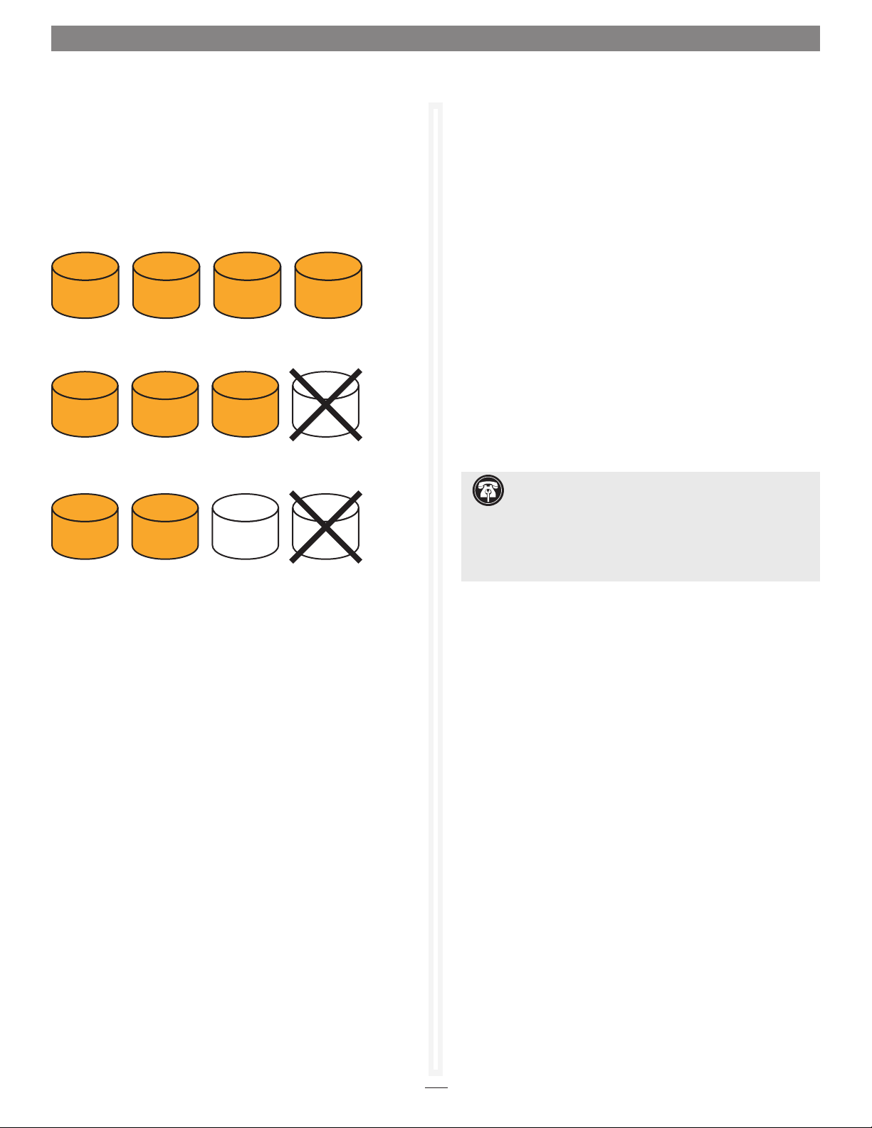
1.8 Recover Data from Offline RAID Groups
Recovery from Replacement of the Wrong Drive
When a drive fails, but the wrong drive is replaced, a rebuild will
not initiate and the RAID group will be taken offline. You should
follow the procedure described in the previous chapter, Identify
and Replace a Faulted Drive, and ensure the correct drive is
replaced.
A functioning RAID 5 RAID group:
321 4
encounters a drive failure, forcing the RAID group into a
degraded state:
321 4
When the wrong drive is replaced, the RAID group is forced
offline!
3A21 4
The situation described above can be corrected. Replace the
erroneously replaced drive with the original drive in the above
example, then identify and replace the failed drive, and then start
a rebuild.
File System Repair Tools
When a RAID group has been made accessible by setting the
drive states appropriately, the host's file system may still have
integrity problems. Supported operating systems have utilities
that try to detect and repair file access issues.
Mac OS X Users: Disk Utility
1. Open Disk Utility, located in the Utilities folder in your
computer’s Applications folder.
2. Select the volume you want to repair in the column on the
left, and then, click the First Aid tab on the right.
3. Click Repair Disk to verify and repair any problems on the
selected volume(s). The results of the repair will be posted in
the window. When no problems are found, it reports: “The
volume “diskname” appears to be OK.” Occasionally, at the
end of a scan, a message similar to the following will appear:
“Scan complete. Problems were found, but Disk First Aid
cannot repair them.”
Support Note: If there are problems found, you should
click Repair Disk to scan again. If the same problem(s) are
found during the second scan, it means First Aid cannot repair the
disk. This indicates that some of your files may be more severely
damaged. To repair this damage, you can either back up your
disk and reformat, or obtain a more comprehensive disk repair
program.
Windows Users: CHKDSK
Chkdsk (Chkdsk.exe) is a Windows command line tool that
checks formatted disks for problems., and then tries to repair any
problems that it finds. For example, Chkdsk can repair problems
related to bad sectors, lost clusters, cross-linked files, and directory
errors. To use Chkdsk, you must log on as an administrator.
Linux Users: FSCK
The system utility fsck (“file system check”) performs a file
system consistency check and interactive repair. It has options to
do a quick check, preen files, preen and clean files, and others.
39
Page 46

1.8 Recover Data from Offline RAID Groups
Using the CLI to Identify a Failed Drive
In addition to the ATTO Configuration Tool’s graphical user interface, you may enter commands in the RAID CLI tab to identify failed drives.
BlockDevScan
The BlockDevScan command displays a list of all attached drives and their usage. Use this command to update the list of drive IDs, which are needed by
other CLI commands.
blockdevscan
6
;ID Vendor Product SerialNumber Capacity InUse Port
;--------------------------------------------------------------------- 0 ST3250310NS 9SF0800F 232.88GB r5
1 ST3250310NS 9SF076NJ 232.88GB r5
2 ST3160812AS-1 5LS25P51 149.10GB r5
3 ST3250620AS 6QF0LJ17 232.88GB r5
Ready.
For members of a RAID group, the InUse column shows the RAID group’s name.
RGDisplay
This is the RAID group display command. Use this command to display all RAID groups and their statuses.
rgdisplay
3
;GroupName Type Interleave Capacity Partitions Members Status
;------------------------------------------------------------------------r5 RAID5 64 KB 447.0GB 1 4 DEGRADED
Ready.
Note: If RGDisplay shows a RAID group is offline, then data recovery methods should be initiated; skip this section and go directly to the
Using the CLI to Enable/Disable Recovery Mode on page 41.
If RGDisplay shows a RAID group is degraded, then it is important to replace the failed drive as soon as possible. RMStatus shows the status
of each of the member drives. If a member is faulted or unavailable, it should be replaced. To match the displayed member to the physical
drive, you can use SESIdentify, which is the preferred method, or BlockDevIdentify, if there is no SES capability.
RMStatus
Next, use RMStatus, the RAID member status command, to display information for each member of the RAID group in question.
rmstatus r5
6
;ID Status RebuildStatus Vendor Product Rev SN
;----------------------------------------------------------------------- 0 ONLINE OK ST3250310NS SDN1 9SF0800F
1 ONLINE OK ST3160812AS-1 H 5LS25P51
2 FAULTED OK ST3250310NS SDN1 9SF076NJ
3 ONLINE OK ST3250620AS K 6QF0LJ17
Ready.
40
Page 47

1.8 Recover Data from Offline RAID Groups
SESIdentify Drive (only valid if enclosure supports SES)
The drive’s fault LED should already be blinking. Use this CLI command to also blink the drive’s activity LED. The ID from the BlockDevScan command
must be used, and not the member ID displayed with the RMStatus command. Match the S/N of the faulted drive (9SF076NJ) from RMSstatus to the
BlockDevScan drive IDs, and use that number to select the correct drive to identify.
sesidentify drive 1
Ready.
sesidentifystop all
Ready.
BlockDevIdentify
Use this command to flash the drive’s activity LED (if the drive is working enough so the activity LED can operate). The ID from the BlockDevScan
command must be used, and not the member ID shown in the RMStatus command. Match the S/N of the faulted drive (9SF076NJ) from RMStatus to
the BlockDevScan drive IDs, and use that number to select the correct drive to identify.
Sometimes, when BlockDevIdentify must be used, the activity LED won't flash because the drive has failed so badly. One possible action is to
blink all the other drives’ LEDs, and find the failed drive by process of elimination.
blockdevidentify 1
Ready.
blockdevidstop
Ready.
Note: If SESIdentify is used, follow it up with the command SESIdentifyStop All to turn off the drive LEDs. When BlockDevIdentify is used,
follow it up with the command BlockDevIDstop (no parameters) to turn the drive LEDs off.
Using the CLI to Enable/Disable Recovery Mode
1. Display the RAID group and RAID group member drives:
rgdisplay
3
;GroupName Type Interleave Capacity Partitions Members Status
;---------------------------------------------------------------------------
r5 RAID5 64 KB 447.0GB 1 4 OFFLINE
Ready.
rmstatus r5
6
;ID Status RebuildStatus Vendor Product Rev SN
;-------------------------------------------------------------------------- 0 ONLINE OK ST3250310NS SDN1 9SF0800F
1 FAULTED OK ST3160812AS-1 H 5LS25P51
2 FAULTED OK ST3250310NS SDN1 9SF076NJ
3 ONLINE OK ST3250620AS K 6QF0LJ17
Ready.
(continued)
41
Page 48

1.8 Recover Data from Offline RAID Groups
Using the CLI to Enable/Disable Recovery Mode (continued)
2. Put the RAID group into Basic or Extreme recovery mode with read and write access::
Set rgrecover r5 basic (or extreme or rebuild)
Ready.
3. Display the RAID group to see the results:
rgdisplay
3
;GroupName Type Interleave Capacity Partitions Members Status
;----------------------------------------------------------------------------
r5 RAID5 64 KB 447.0GB 1 4 RECOVER
Ready.
4. Display the RAID group members to see the results:
rmstatus r5
6
;ID Status RebuildStatus Vendor Product Rev SN
;--------------------------------------------------------------------- 0 ONLINE OK ST3250310NS SDN1 9SF0800F
1 ONLINE OK ST3160812AS-1 H 5LS25P51
2 ONLINE OK ST3250310NS SDN1 9SF076NJ
3 ONLINE OK ST3250620AS K 6QF0LJ17
Ready.
Once as much data as possible is retrieved from the drives, the recovery mode should be disabled and the faulted drives removed from the
system.
5. Turn off the recovery mode:
set rgrecover r5 disable
Ready.
Using the CLI to Enable Recovery with Writes
On occasion, the data that has been disrupted is part of the file system on the disk drives. When this is the case, it is useful to run the file system repair
tools for your operating system. This requires write access to the drives.
WARNING: Use the RGRecoverWithWrites command only when necessary, and use with caution!
Put the RAID group into Basic or Extreme recovery mode with read and write access:
set rgrecoverwithwrites r5 basic (or extreme)
Ready.
Run the appropriate file system repair utility prior to recovering data from the drives.
42
Page 49

1.8 Recover Data from Offline RAID Groups
Degraded RAID group and its assosciated drive information displayed when the Sonnet RAID controller is selected
Figure 29
Starting a recovery rebuild operation on a faulted, offline RAID group
Figure 30
43
Page 50

1.8 Recover Data from Offline RAID Groups
Starting a basic recovery operation on a faulted, offline RAID group
Figure 31
44
Page 51

1.9 SNMP Configuration
SNMP is a standard network protocol that provides the ability to
monitor SNMP enabled systems from anywhere on the network.
Once configured, 3rd party MIB (Management Information Base)
browsers on a Management Station can be used to retrieve the current
configuration and receive TRAP messages when significant events occur.
Via the Configuration Tool, SNMP is supported only for the Sonnet
3 Gb/s RAID controller (listed as an ExpressSAS R380).
The ATTO SNMP agent has two modes, depending on your
configuration. If the only SNMP agent on your server is the
ATTO agent, the mode should be Enabled. If you have other
SNMP agents running and you want them to integrate their data
into a single tree of information or if you want to use advanced
SNMP features, choose SubAgent mode.
Definitions
• SNMP - Simple Network Management Protocol
• Network Node - An addressable device attached to a computer
network.
• Management Station - The host system that monitors network
nodes.
• Trap - An alert that is sent to a management station by agents.
• Agent - A software process on the system being monitored that
responds to queries using SNMP to provide status and statistics
about a network node.
• SubAgent - A software process on the system being monitored
that responds to SNMP queries from another agent, instead of
a MIB (Management Information Base) browser. The request
from the other agent is generated when it is contacted by a MIB
browser.
Details
The ATTO SNMP agent supports protocol versions 1 and 2c.
Communication with the agent requires UDP over IPv4. The ATTO
specific information can be found under “attotech” in the “enterprises”
node (1.3.6.1.4.1.4547). Read-only support is provided.
Enabled Mode
This mode of operation provides Management Stations with
basic information for the standard OID (Object IDentifier) tree,
as well as the ATTO specific information. While this mode will
also work if a system service is installed and running, the ATTO
agent must be configured to listen on a different port than the
system service to ensure both function properly. This mode is
required to support SNMP if the system SNMP service (such as,
Windows SNMP service or snmpd for OS X and Linux) is not
already running.
SubAgent Mode
This mode of operation relies on the operating system’s SNMP
service being installed as a Master Agent and running. All
Management Station requests must be directed to this Master
Agent, not the ATTO agent. It is expected that only experienced
SNMP administrators will use this mode, as installing and
configuring the operating system services are beyond the scope
of this document. Examples are Windows SNMP services, or the
open-source Net-SNMP package.
In this mode, the system service is automatically reconfigured so
that when the service receives requests for the ATTO branch of the
OID tree, the request is delegated to the ATTO agent through the
loopback interface on a different port. While the primary benefit
of subagent mode is to allow the Master Agent to handle most
requests directly (the operating system services implement many
more MIBs than the ATTO agent), and to allow multiple subagents
to be merged into a single OID tree, this mode can be used to
enable features that are not supported by the ATTO agent.
For example, if the system service supports version 3 of the
protocol, all communication over the network between the
Management Station and the service can be encrypted using the
desired privacy options of version 3. The system service will then
communicate to the ATTO agent using one of the supported
protocols.
Note: For security purposes, the ATTO agent will only respond to
requests through the loopback interface when in subagent
mode. If the system service is stopped, the ATTO agent will be
inaccessible from any other host on the network.
Note: Other features that are not directly supported by the ATTO agent,
but can be enabled with this configuration include source address
filtering and stronger authentication than simple community
strings provide. All of these features depend on properly
configuring the system service, and are beyond the control of the
ATTO agent. Refer to the documentation for the system service to
determine how to enable these features.
Note: On Windows Vista Service Pack 1 and Windows Server 2008, a
bug in the Microsoft SNMP service prevents subagent mode from
working correctly. This is a known issue that requires a hotfix:
http://support.microsoft.com/kb/950923. The bug has been
fixed in Service Pack 2. Enabled mode is not affected, nor is the
Net-SNMP service if that is being used as a replacement for the
Microsoft service.
Note: The Net-SNMP service that ships with Mac OS X 10.4 lacks the
functionality needed to support subagent mode. To work around
this, you need to use the enabled mode or build the Net-SNMP
package from source with proxy support enabled.
45
Page 52

1.9 SNMP Configuration
Disabled Mode
This mode disables the operation of the ATTO SNMP agent. Any
network ports it has open to support SNMP are closed, making
it inaccessible to any Management Station. The system service
will not forward requests to it, and no TRAPs are sent out when
events occur.
Basic Setup
The ATTO SNMP agent can be configured through the SNMP tab
on the localhost node. When you first enter the SNMP tab, and
until you commit a new mode, the SNMP mode will be Disabled.
The various settings can be manually edited, but the simplest way
to enable SNMP support in this case is to click the Default button
and then click Commit. This will load the proper settings based
on your current system configuration, and then reconfigure the
agent to use them. The operational mode (enabled or subagent)
and port will be selected based upon whether or not an operating
system SNMP service is running.
Note: The System Service and TRAP Service states are not updated
dynamically as they change in the system. They can be
manually updated at any time by clicking Refresh.
Note: In order to properly secure access to the agent from the local
machine, it is suggested you change the default string in the
Communities list before committing the default settings.
This basic setup will allow you to browse the information that is
made available by the agent with a 3rd party application, but will
not send out TRAPs. TRAP destinations are network specific, and
cannot be determined programmatically.
Configuration Options
Agent Port
This value specifies the UDP port that the ATTO SNMP agent
listens on for incoming Management Station requests. The
port cannot be used by any other process on the system, or the
behavior of both the agent and the other process is undefined.
The standard port value for SNMP is 161, but that is not the
default value in subagent mode, because it is assumed that the
system service is using that port.
Note: A binding error may not occur if the port is already in use. If you
are not sure if a port is in use, use the netstat command.
In enabled mode, this is the port the Management Station uses
to communicate with the agent. In subagent mode however,
the agent will not respond on this port to Management Station
requests from a different machine. The port the Management
Station needs to use is the system service’s port.
Communities
This is a list of community strings accepted by the agent when
it receives an incoming request. If a Management Station makes
a request and provides a community string that is not in this
list, the request is dropped by the agent. If authentication traps
are enabled, one will be sent to each configured destination.
The list can be manipulated through the Add, Edit and Remove
buttons below it. An existing community must be selected to edit
or remove it. A valid community string has a length between 1
and 128 (inclusive) and can include any keyboard character. See
Figure 32 on page 49
Note: In subagent mode, only a single community can be specified
since that is the community used by the Master Agent when
talking to the ATTO SNMP subagent. The communities that
Management Stations must use are configured through the
system service.
Note: For added security in subagent mode, you should change the
default community string. The agent cannot tell the difference
between a local Management Station request and a request from
the system service, which means a local user can bypass the
authentication checks done by the system service if they know
this community string and the agent’s port.
Send Authentication TRAP
When checked, the agent will send a TRAP to the configured
TRAP destinations indicating that a Management Station
attempted to contact the agent and used a community string that
is not in the community list.
Note: In subagent mode, this may only be useful for debugging. The
system service will perform Management Station authentication
based on its configuration, and only forward the request to the
ATTO agent once the Management Station is authenticated. Since
the system service is reconfigured as needed to use the community
string on this pane when forwarding requests, there should not be
authentication errors when the agent processes requests from the
system service. The system service usually has the same option
that can be enabled to see these authentication failures.
Enable TRAPs
When checked, the agent will send traps to the configured
destinations, if any, if the agent itself is not disabled. See Figure
33 on page 49.
46
Page 53

1.9 SNMP Configuration
Trap Destination Table
This table lists the host address and community string used
for each destination when a trap is triggered. The host column
consists of the hostname or IP address of the Management
Station to which the traps are sent, and the UDP port on which
the trap receiver is listening. The community column displays
the community string sent with the trap to that host. If the
community string is not in the list of communities accepted by
the receiver, the receiver will ignore the trap message. See Figure
34 on page 50.
The table can be manipulated through the Add, Edit and Remove
buttons below it. An existing destination must be selected to edit
or remove it. A valid community string has a length between 1
and 128.
Note: The trap configuration is completely independent of the enabled
or subagent modes, but no traps are sent if the agent is disabled.
Many operating systems have a trap receiver service as part of
their SNMP package, which can be configured to do various
things when it receives a trap, such as writing to a log file or
forwarding to another destination. In a similar manner to the
way the system service and subagent mode can enable SNMPv3
support, the operating system trap service can be configured
to translate traps it receives into SNMPv3 traps, with optional
privacy, authentication and INFORM support. The ATTO agent
then only needs to specify a single trap destination to this
service in order to enable SNMPv3 support over the network.
The manner in which the system service is configured is system
specific, and beyond the scope of this document.
Test
This button will validate the settings displayed on screen,
and then send a warm Start trap to each of the displayed trap
destinations as if the displayed settings had been committed.
Selecting disabled mode, unchecking the enable traps option
or removing all trap destinations will prevent the test trap
from being sent. Once an acceptable configuration is entered, a
commit is needed for it to take effect.
Note: The test is not performed by changing the settings used by the
agent at the time of the test, so testing will have no effect on any
concurrent Management Station requests.
Save MIBs
This button will save the non standard MIBs implemented by
the agent to the user specified directory as individual text files,
therefore they can be loaded into a MIB browser. If one of the
files already exists in that directory, the user is prompted to
overwrite or skip the file, or cancel the operation.
Control Buttons
Commit
This button will reconfigure the ATTO agent to use the settings
as they are currently displayed on the screen, after validating
them to the extent possible. The settings are persistently stored,
so that they are available after a reboot. If necessary, the system
service will be reconfigured to support the agent’s current
operational mode.
Restore
This button will update the display to reflect the settings the
agent is currently using, rolling back any changes made in the
pane that have not been committed. Since these are the current
settings, they do not need to be committed.
Default
This button will update the display with the simplest
configuration, based on the current system configuration. For
example, if the operating system service is detected as running,
the default mode is subagent. Otherwise, the mode is enabled
and the registered SNMP port is displayed.
WARNING: Since it isn’t possible to determine trap destinations and
community strings programmatically, all trap destinations
will be cleared.
47
Page 54

1.9 SNMP Configuration
Troubleshooting
Requests from an MIB browser time out:
• Ensure the agent is not disabled
• Ensure the Management Station is using the port for the system
service if the agent is in subagent mode or the port displayed on
the SNMP pane if the agent is enabled.
• Ensure the community string used by the Management Station
is accepted by the system service when in subagent mode or
is displayed in the communities list on the SNMP pane if the
agent is enabled. Be sure the Send Authentication TRAP option
is selected, committed, and then try again. If the community
is a problem, each of the configured trap destinations will be
notified.
• Ensure the Management Station is using SNMPv1 or SNMPv2c,
unless the system service is being used.
• If in subagent mode, the system service may be misconfigured.
Try enabling the agent and using the Management Station to
talk directly to it. You will have to change the port value and
likely the community string.
Traps are not received when testing
• Ensure the agent is not disabled
• Ensure the Enable TRAPs option is checked.
• Ensure a trap recipient is properly configured and running on
each machine in the destination table, at the specified port.
• Ensure the community associated with the destination is in the
trap recipient’s community list.
RAID OIDs are skipped when walking or the tables are empty
• Ensure the driver for the RAID controller is installed. This can
be seen on the Basic Info pane for the controller.
Note: To properly work with Net-SNMP when configured as a
subagent, the Net-SNMP package has to be installed “With
Windows Extension DLL Support”. This is an option during the
installation of Net-SNMP.
Note: The architecture of Net-SNMP installed has to match the OS;
i.e. if you are using a 64-bit OS the 64-bit version of Net-SNMP
must be installed.
48
Page 55

1.9 SNMP Configuration
SNMP tab with the Enable Traps option selected
Editing the Community string
Figure 32
Figure 33
49
Page 56

1.9 SNMP Configuration
Editing the trap destination
Figure 34
50
Page 57

1.10 Configuration Tool Troubleshooting
You may see an error message informing you about an unexpected event
or incorrect information discovered by the application. Using the help text
presented with the error message, correct the issue before proceeding.
Warnings and error messages are displayed in the Status pane.
Messages from NVRAM Tab Actions
• An error occurred loading NVRAM data.
The first time a channel is highlighted, the Configuration Tool
attempts to read NVRAM from the card. This message usually
indicates that the Configuration Tool could not communicate
with the driver, probably because the application does not
support the driver version in use.
• Warning: NVRAM could not be read, defaults returned.
NVRAM is corrupt and the driver returns to the default
configuration. The defaults are presented via the graphical user
interface. These defaults may be modified but the defaults or
modifications must be committed (saved) in order to correct
NVRAM.
• An error occurred updating the NVRAM.
The driver cannot load the new settings on the card; no changes
are made to the card.
Feature bounds checking
When the Commit button is clicked, each NVRAM feature
is validated before being sent to the card. If any one of these
features is deemed inappropriate based on the implemented
checks, further NVRAM feature validation checks are stopped
and the message is displayed.
Messages from Flash Tab Actions
• This is not a flash file, or it is corrupt.
The ATTO-created flash file is corrupt or the Configuration Tool
does not recognize the file as a flash file. Only ATTO-created
flash files may be selected using the flash file dialog box.
• This HBA is not compatible with the selected flash file.
ATTO flash files are created based on the type of card flashed.
Only certain ATTO flash files are compatible with the Sonnet
RAID controller. When a flash file is selected, it is inspected to
determine whether it is compatible.
• A valid file was not selected.
You clicked the Cancel button on the flash file selection dialog.
• An error occurred reading from the flash file, the file may be
corrupt.
You selected a compatible flash file but the contents are corrupt.
• An error occurred updating the flash.
You tried to flash a card when the firmware was not able to
accept a flash.
• The card has been prepared for firmware updating, but the
machine must be rebooted for the changes to take effect.
You need to repeat this process after rebooting to actually
update the firmware.
Some firmware upgrades need to prepare the existing firmware
in order to successfully update the controller. Rebooting enables
the changes made during the preparation process to take effect,
and the same file should be flashed again.
• Execution Throttle is greater than the maximum allowable
value of 255. No NVRAM configuration changes have been
made to your card. The exact message varies based on the first
field with an out-of-range value.
51
Page 58

52
Page 59

2.0 Drive Performance Testing
The ATTO Configuration Tool’s drive performance testing feature
records the performance level of a drive in a RAID group under an I/O
(input/output) load generated by a host application on your computer.
The information can be used to compare the performance of each drive
relative to others.
The Configuration Tool’s performance test application measures
the data transfer rates in Megabytes per second (MB/sec.) which
elapse from the time the start button is clicked until the stop
button is clicked. Drive performance can be measured for any
combination of single drives within a RAID group or across
multiple RAID groups, or for all the drives in a selected RAID
group.
Note: The performance test can only be performed on drives which
belong to a RAID group.
The Drive Performance dialog box displays individual statistics
for each drive selected. After you start the I/O load application,
the collection of these statistics begins when the Start button is
pressed and continues until the Stop button is pressed. You may
press the Reset button and restart a test at any time.
The Configuration Tool application can be closed after starting
the performance test and re-opened to show the statistics from
the most recent test.
9. Stop the I/O any time after you have stopped the
performance test.
1. Start the I/O-generating application on your computer.
2. Select the Sonnet RAID controller from the Device Listing
pane.
3. Select the RAID tab in the right pane.
4. Select the drives to be tested:
• Select individual drives from the Attached Drives pane.
• Select a single RAID group in the Groups pane.
5. Select RAID Management > Performance from the
application menu.
6. The Performance dialog box displays. See Figure 35 on
page 54.
7. Click the Start button.
8. Click the Stop button to halt monitoring.
Click the Reset button at any time to reset the performance
values to zero.
You can close the Performance box while monitoring is
in progress, and then open it later to see the performance
results.
53
Page 60
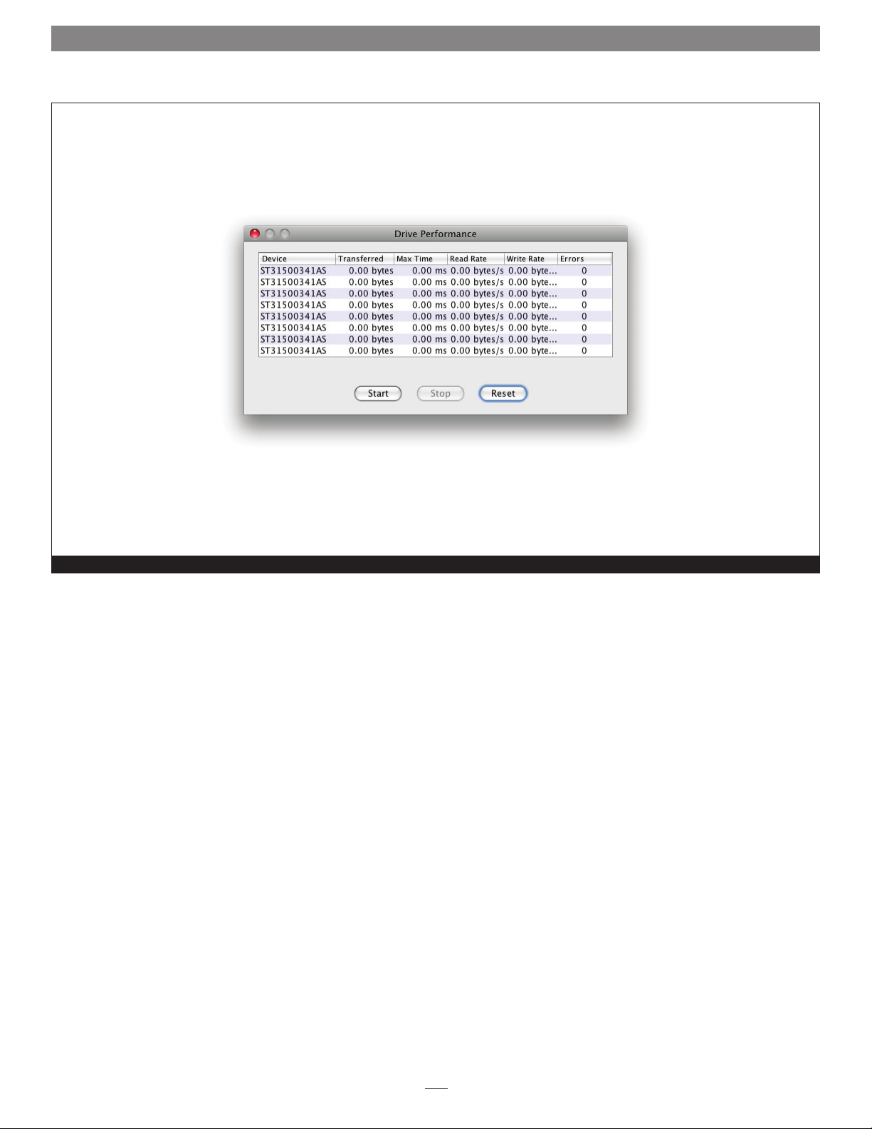
2.0 Drive Performance Testing
Drive Performance window before starting the test
Figure 35
54
Page 61

2.1 Windows Only - ATTO Disk Benchmark
The ATTO Utilities for Windows are installed from the CD that was
included with your Sonnet RAID controller. Only one utility, Disk
Benchmark, may be used with your Sonnet RAID storage system.
Disk Benchmark measures peak and sustained throughput for
disk reads and writes. See Figure 36 on page 56. You may locate
the Disk Benchmark application in the ATTO HBA Utilities folder
within your system’s Applications folder.
1. Launch the application.
2. Select the drive letter for the disk to benchmark.
3. Select the transfer sizes to test.
4. Select the I/O option.
5. Click the Start button.
6. Wait for benchmark to run through the desired transfer sizes.
7. The Test Results Display at the bottom of the window is
updated as the test progresses. The y-axis of the graph
represents the transfer sizes in the selected range. The x-axis
represents the transfer speeds in MB/sec. I/O speeds in KB/sec.
for each transfer size are displayed textually to the right of the
graph.
Support Note: Additional information on using Disk
Benchmark is available by accessing the Help menu in the
application.
Benchmark Fields
The benchmark fields include:
• Drive: Select the logical drive to benchmark. A test can be
performed on any system drive.
• Transfer Size: Select the range of transfer sizes used for reading
and writing data to the test drive. Transfer speeds are displayed
for each size in the range. If the first size is greater than the
second size, the test is not performed for any transfer size.
• Total Length: Select the total size of the data file to be created
on the test drive. This file is deleted when testing completes.
• Direct I/O: If this option is checked, file I/O on the test drive
is performed with no system buffering or caching. Combine
this option with Overlapped I/O for maximum asynchronous
performance
Radio Button Group
• Overlapped I/O performs queued I/O. Upon selection, the
Queue Depth option displays to select the maximum number of
read or write commands that may be executed simultaneously.
8. Click the Stop button to stop the test. When the test
completes, the results can be saved or printed.
If errors were detected, a dialog box displays the errors in a table
with the following four columns and a button:
• Benchmark Transfer Size: transfer size at which the error
occurred
• Buffer Index: index into the data block at which the error
occurred
• Actual Value: the value read from the file
• Expected Value: the value written to the file
• Log to File: Logs the error table to a *.log file and closes the
dialog. The file is given the same name as the test file and saved
in the same directory. If the test was not previously saved, errors
are logged to the generic file Bench32Error.log in the root of
the test drive. If the log file already exists, the new errors are
appended to the previously recorded errors. This is the only way
to save detected errors. They are not saved in the test document
file.
If the I/O comparison option was selected and errors were not
detected, the message “No errors detected” is displayed.
• I/O Comparison compares the data read from the test file to
the data written on a per block basis. You can select the data
pattern for comparison from the Test Pattern drop-down box.
• Run Continuously runs the test continuously for a specified
number of minutes. The test stops before the specified time if
any errors are detected.
• Neither: Select if you do not want to perform overlapped I/O or
I/O comparisons.
The following fields do not affect the benchmark but are
informational, providing documentation of the test environment.
• Stripe Group: If the test drive is a stripe group, select its name
from the list box. The names and quantities of drives in the
stripe group are printed to the Description box. Select Clear to
clear the contents of the Description box.
• Controlled by displays all Sonnet RAID controllers in the
system.
• Description: Enter additional information about the test that
can be saved or printed. Be sure to enter additional information
after making a selection from the Stripe Group drop down box,
as this erases the current description.
55
Page 62

2.1 Windows Only - ATTO Disk Benchmark
Multiple Benchmark Testing
Disk Benchmark supports four command line parameters for
uninterrupted testing:
• testfile opens and executes the test named testfile with the
extension .bmk.
• textfile opens the text file named textfile. This file contains a
list of test file names that have an extension of .bmk. Each test
in this list is opened and executed in order. Stopping one test in
the list prevents further tests from being executed. Error logging
is the same as the command line parameter testfile, but all
errors generated from all tests in the list are logged to one file:
textfile.log.
Disk Benchmark screens before and after a test has been run
• /p testfile: Same as testfile, only the test is printed to the
default system printer instead of being executed.
• /p textfile: Same as textfile, only the tests in the list are printed
to the default system printer instead of being executed.
Figure 36
56
Page 63

2.2 ATTO Disk Benchmark Troubleshooting
The following suggestions may help if you encounter problems with
Disk Benchmark.
• Use Windows Device Manager to check and verify that all
drives are visible to the operating system.
• If drives are not listed, check the connections between the drive
enclosure and the RAID controller card, and verify that all
drives are fully seated in their bays.
• Make sure that the enclosure is powered up and has completed
its self check before booting your computer.
• Reboot your system any time you make changes to a RAID
group (after the RAID group has been rebuilt).
• As a last resort, you may use the ATTO Boot Configuration
Utility to low level format a troublesome device. However, this
erases all information on the disk.
• Have you partitioned your drive, and then activated that
partition?
• Did you format the drives for use with your operating system?
If problems persist, contact Sonnet customer service.
57
Page 64

58
Page 65

Appendix A - CLI ASCII-Based Interface
The RAID CLI tab enables experienced users to send Command Line
Interface (CLI) commands to the Sonnet RAID controller to configure,
test, and otherwise interact with attached storage.
WARNING: Do not use CLI unless you are directed to by
a Sonnet technician, as changing parameters may cause
loss of data and/or disruption to performance and reliability
of the Sonnet RAID controller. The ATTO Configuration Tool
interface is the preferred method to operate and manage the
Sonnet RAID controller.
The command line interface uses a set of ASCII-based commands
to control configuration and diagnostic tasks. See Figure 5 on
page 5.
• CLI commands are context sensitive and generally follow a
standard format
[Get|Set] Command [Parameter1|Parameter2]
followed by the return or enter key
• CLI commands are case insensitive: you may type all upper or
all lower case, or a mixture. The use of mixed upper and lower
case in this manual and the help screen are for clarification
only.
• The get form returns the value of a parameter or setting and is
an informational command.
• Responses to get commands are followed by Ready.
• The set form is an action that changes the value of a parameter
or configuration setting. It may require a SaveConfiguration
command and a restart of the system before it is implemented.
The restart can be accomplished using a separate
FirmwareRestart command. A number of set commands may
be issued before the SaveConfiguration command.
• Responses to set commands are either an error message
or Ready. *. The asterisk indicates you must use a
SaveConfiguration command to finalize the set command.
• Set commands which do not require a SaveConfiguration
command, defined as immediate commands, are immediately
executed.
Support Note: Using certain CLI commands during
normal operation can cause a performance drop. Once
command actions are complete, performance should return to
normal levels.
• Commands generally have three types of operation: get, set and
immediate.
Figure A-1 Symbols, typefaces, and abbreviations used to indicate functions and elements of the command line interface used in this manual.
Symbol Indicates
[ ] Required entry
< > Optional entry
| Pick one of
n – n A range (6 – 9 = 6, 7, 8, 9)
BlockDevID Index designation of a block device not assigned to any other RAID group; the index of a block device provided by the
BlockDevScan command. 0<=n<=63
GroupName The name of the RAID group to which the block device is assigned, or blank if the drive is available
MemberIndex Index designation of a RAID group member as found in the RMStatus command
PartIndex Index designation of a partition as found in the PartitionDisplay command
SASIndex Index designation of SAS drives as found in SASTargets
TID Target ID 0<=n<=255
i
Page 66

Appendix A - CLI ASCII-Based Interface
CLI Error Messages
The following error messages may be returned by the Command
line Interface
ERROR Invalid Command. Type “Help“ for command
list.
ERROR Command Not Processed
ERROR Wrong/Missing Parameters
ERROR Invalid Hot Spare Serial Number
ERROR Invalid RAID GroupName
ERROR Invalid RAID Group State
ERROR Insufficient number of RAID Group members
ERROR RAID Group does not exist
ERROR No RAID Groups found
ERROR Invalid RAID Type
ERROR RAID Group is already unmapped
ERROR Invalid Block Device Index
ERROR Cannot perform operation. RAID Group has
mapped Partitions
ERROR Cannot perform operation. RAID Group has
Outstanding Commands
ERROR Block Device at specified index no longer
available
ERROR Insufficient RAID Group members for RAID
type
ERROR Incorrect number of RAID Group members for
QuickVideo configuration
ERROR Invalid Virtual Drive ID
ERROR Specified capacity is invalid
ERROR Too many Indices specified
ERROR Only one add storage operation is permitted
at any given time
ERROR No free block devices
ERROR Cannot benchmark a drive that is being
initialized
ERROR Invalid RAID MemberIndex
ERROR Invalid RAID Member State
ERROR Missing RAID Member
ERROR Invalid RAID Member Capacity
ERROR Invalid Partition Index
ERROR Maximum number of RAID Groups exceeded
ERROR Maximum number of Partitions exceeded
ERROR Invalid number of Partitions
ERROR Maximum number of RAID Members exceeded
ERROR Maximum stripe width
ERROR Invalid number of Partitions specified
ERROR Invalid Span Depth specified
ERROR Cannot perform operation on mapped Partition
ERROR Specified drive is not being monitored
ii
Page 67

Appendix A - CLI ASCII-Based Interface
CLI Summary
The following chart summarizes the Command Line Interface
commands, their defaults, and an example of how to enter the
commands. Please note that commands which have no default
values have a blank entry in that column of the table.
WARNING: Do not use the CLI unless you are directed
to by a Sonnet technician, as changing parameters may
cause loss of data and/or disruption to performance and
reliability of the Fusion storage system.
Command Default Example
AutoMap automap
AutoMapOnBoot enabled set automaponboot enabled
AutoResume rebuild = enabled, erase = disabled, initialize
= enabled
BlockDevClean blockdevclean 30
BlockDevIdentify blockdevidentify 30
BlockDevIDStop blockdevidstop
BlockDevInfo blockdevinfo 30
BlockDevScan blockdevscan
ClearEventLog cleareventlog
Date set date 03/03/2009
DeleteScheduledTasks deletescheduledtasks
DisplayScheduledTasks displayscheduledtasks
DriveAssureReport driveassurereport raidgroup1
DriveHealth disabled set drivehealth enabled
DriveHealthDisplay drivehealthdisplay all
DriveHealthStatus drivehealthstatus
DriveTest drivetest begin
DriveTestClearList drivetestclearlist all
set autoresume erase enabled raidgroup1
DriveTestConfig not initiated set drivetestconfig read
DriveTestList get drivetestlist all
DriveTestStatus get driveteststatus
DumpConfiguration dumpconfiguration
DumpEventLog dumpeventlog
EventLog enabled set eventlog disabled
EventLogFilter all all all set eventlogfilter gen info all
Help help eventlog
HSAdd hsadd 3
iii
Page 68

Appendix A - CLI ASCII-Based Interface
Command Default Example
HSDisplay hsdisplay
HSRemove hsremove 3
Info info
IsReserved isreserved
Metrics metrics display all
OEMConfigFile get oemconfigfile
Partition partition alpha1 6 4 GB
PartitionDisplay partitiondisplay alpha1
PartitionMerge partitionmerge all
PartitionSplit partitionsplit alpha1 22 2
PartitionWriteCache set partitionwritecache enabled
RAIDRebuildPriority same set raidrebuildpriority low
RAIDSpeedWriteLimit 8 set raidspeedwritelimit 16
RebuildContinueOnError disabled rebuildcontinueonerror raidgroup1
Reserve reserve
RestoreConfiguration restoreconfiguration default
RGAddStorage rgaddstorage raidgroup1 span commit
RGAutoRebuild disabled set rgautorebuild all enabled
RGCancelAddStorage rgcanceladdstorage raidgroup1
RGCancelMediaScan rgcancelmediascan raidgroup1
RGCommit rgcommit all
RGCreate rgcreate raidgroup1 raid0
RGDiskWriteCache set rgdiskwritecache all disabled
RGDisplay rgdisplay all
RGErase rgerase raidgroup1
RGHaltConversion rghaltconversion raidgroup1
RGHaltErase rghalterase raidgroup1
RGHaltInitialization rghaltinitialization raidgroup1
RGHaltMediaScan rghaltmediascan raidgroup1
RGHaltRebuild rghaltrebuild raidgroup1
RGMediaScan rgmediascan raidgroup1 verify
RGMediaScanErrorReport set rghdparameter raidgroup1 30
RGMemberAdd rgmemberadd raidgroup1 30
RGMemberRemove rgmemberremove raidgroup1 30
RGPrefetch set rgprefetch raidgroup1 3
RGRebuild rgrebuild raidgroup1
iv
Page 69

Appendix A - CLI ASCII-Based Interface
Command Default Example
RGRecover rgrecover raidgroup1 rebuild
RGRecoverWithWrites rgrecoverwithwrites raidgroup1 basic
RGResumeConversion rgresumeconversion raidgroup1
RGResumeErase rgresumeerase raidgroup1
RGResumeInitialization rgresumeinitialization raidgroup1
RGResumeMediaScan rgresumemediascan raidgroup1
RGResumeRebuild rgresumerebuild raidgroup1
RGSectorSize 512 setrgsectorsize raidgroup1 8192
RGSpanDepth 1 set rgspandepth raidgroup1 22
RGSpeedRead all disabled set rgspeedread raidgroup1 enabled
RGUnmap rgunmap raidgroup1
RGWaitTimeout 3 rgwaittimeout 30
RMStatus rmstatus raidgroup1
Route route host 1 raid alpha1 6
RouteDisplay routedisplay 03 124
SASPortList sasportlist
SASTargets sastargets
SaveConfiguration saveconfiguration
SerialNumber get serialnumber
SES enabled set ses disabled
SESAlarmTest
SESDiskFailureAlarm disabled set sesdiskfailurealarm enabled
SESEnclosures sesenclosures
SESIdentify off set sesidentify all
SESIdentifyStop sesidentifystop all
SESMute
SESPoll 30 set sespoll 0
SESStartingSlot 1 set sesstartingslot 0
SESStatus
Time set time 03:32:30
TimeZone EST set timezone pst
VerboseMode enabled set verbosemode disabled
VirtualDriveInfo virtualdriveinfo
WrapEventLog enabled set wrapeventlog disabled
v
Page 70

Appendix A - CLI ASCII-Based Interface
CLI Command Explanations
Command line interface commands are listed alphabetically with
explanations of what they are used for, their defaults and syntax.
WARNING: Using CLI without contacting a Sonnet
technician is not recommended because changing
parameters may cause loss of data and/or disruption to
performance and reliability of the Fusion storage system.
• AutoMap (Immediate, Disabled on Error)
Automatically maps each RAID partition to a Target ID on the
host system (maximum 256 maps allowed). If the optional
passthrough parameter is entered then AutoMap stores maps
for currently connected SAS/SATA Pass Through Devices.
AutoMap <passthrough>
• AutoMapOnBoot (Enabled, Disabled on Error)
Regulates the automatic detection and mapping of RAID groups
at startup.
set AutoMapOnBoot [enabled | disabled]
get AutoMapOnBoot
• AutoResume
Regulates the AutoResume features for interrupted rebuild,
erase, and initialization operations at startup. Optional
parameter GroupName specifies the RAID group to operate on.
If no GroupName is specified, the command operates on all
existing RAID groups.
set AutoResume [Rebuild | Erase |
Initialization | MediaScan | all] [enabled |
disabled] <GroupName>
get AutoResume [rebuild | erase |
initialization | MediaScan | all]
• BlockDevClean (Immediate, Disabled on Error)
Removes any RAID configuration data from the block device
with the specified BlockDevID. BlockDevId is the index of a
block device provided by the BlockDevScan CLI command.
BlockDevClean [BlockDevID]
• BlockDevIdentify (Immediate, Disabled on Error)
Turns on a drive activity LED on the Fusion drive enclosure
for a specified drive until a BlockDevIDStop command is
given. Use either the RAID group name and member index, or
BlockDevId. BlockDevId is the index of a block device provided
by the BlockDevScan CLI command.
WARNING: The BlockDevIdentify command is intended
for diagnostic purposes only. Executing this command may
adversely impact the performance and throughput of the Fusion
storage system for the time that the LED is illuminated.
BlockDevIdentify [[Groupname MemberIndex] |
BlockDevID]
• BlockDevIDStop (Immediate, Disabled on Error)
Turns off the drive activity LED on the Fusion drive enclosure
that was activated with the BlockDevIdentify command.
Specify the RAID group name and member index, BlockDevId,
or no parameters (which will turn off all previously identified
drive’s LEDs). BlockDevId is the index of a block device
provided by the BlockDevScan CLI command.
BlockDevIDStop <[GroupName MemberIndex] |
BlockDevID>
• BlockDevInfo (Immediate, Disabled on Error)
Lists detailed information about connected physical block
devices along with any potential RAID group association.
BlockDevInfo [BlockDevID | all]
• BlockDevScan (Immediate, Disabled on Error)
Lists all currently connected physical drives along with any
potential RAID group association. Each block device listed is
assigned a unique index at the time of the scan to identify
drives for other CLI operations.
BlockDevScan
• ClearEventLog (Immediate)
Clears the contents of the event log.
ClearEventLog
WARNING: All RAID group setup information is lost
when the BlockDevClean command is performed,
therefore all data is lost. Back up your files before performing
this command.
• Date
Sets the current date. The date range is 01/01/2000 to
12/31/2099.
set Date [MM]/[DD]/[YYYY]
get Date
• DeleteScheduledTasks (Immediate, Disabled on Error)
Deletes a scheduled task with the ID returned by
DisplayScheduledTasks.
DeleteScheduledTasks [Id]
vi
Page 71

Appendix A - CLI ASCII-Based Interface
• DisplayScheduledTasks (Immediate, Disabled on Error)
Displays all outstanding scheduled tasks.
DisplayScheduledTasks
• DriveAssureReport (Immediate, Disabled on Error)
Displays drive timeout error statistics for all member drives in a
specified RAID Group.
DriveAssureReport [GroupName]
• DriveHealth (Disabled, Disabled on Error)
Changes the system’s ability to acquire drive health data from
connected drives. Issuing this command during I/O operations
may adversely affect performance.
set DriveHealth [enabled | disabled]
get DriveHealth
• DriveHealthDisplay (Immediate, Disabled on Error)
Retrieves and displays S.M.A.R.T. (Self-Monitoring, Analysis and
Reporting Technology) data from SATA drives, and medium
defect and information exceptions counts from other drives.
Issuing this command during I/O operations may adversely
affect performance.
DriveHealthDisplay [BlockDevID | all]
• DriveHealthStatus (Immediate, Disabled on Error)
Displays the current S.M.A.R.T. status of specified SATA disk
drives, and medium defect and information exceptions counts
from other drives.
DriveHealthStatus [BlockDevID | all]
• DriveTestConfig (Disabled on Error)
Configures the drive test to perform one of the following
operations: initialize (destructive write-only), read
(nondestructive read-only), verify (destructive verify),
mediascan (destructive for sectors with medium errors), or initverify (destructive write-read-verify). The test is not started until
the DriveTest Begin command is given. A new configuration
may not be set while a drive test is being performed.
set DriveTestConfig [init | read | verify |
mediascan | init-verify]
get DriveTestConfig
• DriveTestList (Disabled on Error)
Specifies the drives to be included in the next drive test.
DriveTestConfig should be set up prior to adding any drives
into the test list. This command can be called with different
eligible BlockDev IDs and each one will be added to the
list. Drives which are part of a RAID group are only eligible
for read drive tests. Additionally, Hot Spare drives are only
eligible for media scan and read drive tests. The all parameter
automatically chooses eligible drives. The test is not started
until the DriveTest Begin command is given.
set DriveTestList [drive [BlockDevID] | all]
get DriveTestList
• DriveTestStatus
Displays the status of the currently running drive test but does
not display performance metrics. If a block device ID is not
running or cannot be found, its state will be idle and percent
complete will be 0.
get DriveTestStatus <drive [BlockDevID]>
• DriveTest (Immediate, Disabled on Error)
Starts or stops a drive test with the previously specified
configuration (refer to DriveTestConfig) and drive list (refer to
DriveTestList). Drives being tested are not available for RAID
configuration or RAID operations. Only one test can be run at a
time.
DriveTest [begin | cancel]
• DriveTestClearList (Immediate, Disabled on Error)
Specifies drives to be removed from the drive test list. The drive
BlockDevID parameter removes the specified drive from the list.
The all parameter removes all drives from the list.
DriveTestClearList [drive [BlockDevId] | all]
• DumpConfiguration (Immediate)
Displays a unit’s configuration to the management interface.
DumpConfiguration
• DumpEventLog
Dumps the contents of the entire event log to the management
interface.
DumpEventLog
• EventLog (Enabled, Disabled on Error)
Regulates event logging. When enabled, records various system
errors to the event log.
set EventLog [enabled | disabled]
get EventLog
vii
Page 72

Appendix A - CLI ASCII-Based Interface
• EventLogFilter (Enabled, Disabled on Error)
Filters data from specific unit subsystems and levels when event
logging is enabled. The specific entries supported are platformdependent. For set commands, the final parameter indicates
whether or not events from the specified subsystem and level
are displayed.
set EventLogFilter [subsys | all] [eventlevel |
all] [all | none]
get EventLogFilter [subsys | all] [eventlevel |
all]
• Help (Immediate)
Displays a list of available commands. If you specify
a command, detailed, command-specific information is
displayed.
Help <command>
• HSAdd (Immediate)
Assigns a drive to the Hot Spare pool.
HSAdd [BlockDevID]
• HSDisplay (Immediate)
Lists all drives in the Hot Spare pool.
HSDisplay
• HSRemove (Immediate)
Removes a drive from the Hot Spare pool
HSRemove [BlockDevID | all]
• Info (Immediate)
Displays version numbers and other production information for
key components. Use the optional brief parameter to display a
more concise subset of system information.
Info <brief>
• IsReserved (Immediate)
Displays the reservation status of the current services session or
interface.
IsReserved
• MediaScanErrorReport (Immediate, Disabled on Error)
Displays media scan error statistics for either a single drive or all
drives in the system
MediaScanErrorReport [BlockDevID | all]
• Metrics (Immediate)
Controls the collection of standard data metrics within a
product based on the command parameters.
Metrics [start | stop | display] [drive
BlockDevID] | all | running]
• OEMConfigFile (Disabled on Error)
Displays the “name” (i.e., the contents of the first record) of the
OEM configuration file stored in persistent memory.
get OEMConfigFile
• Partition (Immediate)
Creates a specified partition with a specified capacity in
Gigabytes (GB), Megabytes (MB), or blocks. The specified
capacity must be smaller than the specified partition’s current
capacity. A new partition is created to acquire the remainder of
the original partition’s space.
Partition [GroupName] [PartIndex] [capacity] [GB
| MB | blocks]
• PartitionDisplay (Immediate)
Lists all the partitions available in the specified RAID group. The
partitions are listed contiguously (as opposed to index order).
GroupName is the ASCII name of the RAID group for which
partitions will be displayed.
PartitionDisplay [GroupName]
• PartitionMerge (Immediate)
Merges the specified contiguous partitions into one partition.
GroupName is the ASCII name of the RAID group containing
the partitions to merge. PartIdx is the index of a partition to
merge, along with a number of contiguous partitions to merge
to that index.
will be merged into a single virtual disk. The RAID group must
not be in a new state. None of the partitions to merge may be
mapped.
PartitionMerge [GroupName] [[[PartIdx] [1-128]] |
all]
• PartitionSplit (Immediate)
Divides the specified partition into one or more partitions
whose capacities are evenly distributed among the capacity of
the original partition. GroupName is the ASCII name of the
RAID group containing the partition to split. PartIdx is the
index of the partition to split. The partition to split cannot be
mapped and the RAID group must not be in a new state.
PartitionSplit [GroupName] [PartIdx] [1-128]
All indicates that all partitions in the RAID group
viii
Page 73

Appendix A - CLI ASCII-Based Interface
• PartitionWriteCache
Enables higher write performance with a small risk of data loss
after a system failure. If disabled, provides a higher level of data
integrity with lower write performance.
set PartitionWriteCache [GroupName] [PartIdx]
[enabled | disabled]
get PartitionWriteCache [GroupName] [PartIdx]
• RAIDRebuildPriority
Sets or displays the RAID rebuild priority. A RAID rebuild
priority set to high gives higher priority to RAID rebuilds and
lower priority to the processing of simultaneous read/write
transactions. A RAID rebuild priority set to low gives lower
priority to the rebuild and a higher priority to read/write
transactions. Set to same, the RAID rebuild and processing
of read/write transactions is the same. If all or no groups are
specified, the system default and all of the individual RAID
groups are set. If a group name is specified, only the specified
group is set.
set RAIDRebuildPriority <GroupName | all> [high
| low | same]
get RAIDRebuildPriority <GroupName | all>
• RAIDSpeedWriteLimit (Disabled on Error)
Sets or displays the limit on the coalescing factor. Warning:
changing the default setting (8) may result in poor performance
or timeouts. A lower setting is recommended when using
multiple initiators. A higher setting may improve performance
with multiple streams of sequential write I/O, but too high a
setting will cause timeouts.
set RAIDSpeedWriteLimit [0 - 32]
get RAIDSpeedWriteLimit
• RebuildContinueOnError
Enables a rebuild to continue to completion even if media read
errors are encountered during the rebuild operation.
set RebuildContinueOnError [GroupName1 | all]
[enabled | disabled]
get RebuildContinueOnError [GroupName1 | all]
• Reserve (Immediate)
Reports the state of CLI reservation for the current CLI session.
If the command reports that reservations are enabled, then
another CLI session has control of parameter modification.
Reserve
• RestoreConfiguration (Immediate, Disabled on Error)
Forces the NVRAM settings to their original defaults when
issued with the default option. The saved option undoes any
changes made to this session since the last save.
RestoreConfiguration [default | saved]
• RGAddStorage (Immediate)
Adds additional storage to an existing RAID group. GroupName
is an ASCII name for the RAID group. MIRROR |STRIPE |SPAN
specifies the method used to expand the storage. Optional
parameter list BlockDeviceID specifies up to 10 indices of
available block devices, provided by the BlockDevScan CLI
command, to be added to the RAID group. If this list is
omitted, the CLI command RGMemberAdd must be used.
Optional parameter commit runs the RGCommit command
automatically and all user data will be erased from each new
member drive. If the parameter is omitted, the CLI command
RGCommit must be entered. Any time before RGCommit is
entered, the command RGCancelAddStorage can be used to
cancel the process. Note: Mirrors cannot be added to a RAID 4,
RAID 5, RAID 6, or DVRAID RAID group.
RGAddStorage [GroupName] [mirror | stripe |
span] <BlockDeviceID | <commit>
• RGAutoRebuild
Enables and disables Auto-Rebuild functionality for one or more
RAID groups. Auto-Rebuild uses drives assigned as Hot Spares,
followed by available drives, as automatic replacements for any
member that fails. Auto- Rebuild is disabled by default.
set RGAutoRebuild [GroupName | all] [enabled |
disabled]
get RGAutoRebuild [GroupName | all]
• RGCancelAddStorage (Immediate, Disabled on Error)
Cancels the RGAddStorage command.
RGCancelAddStorage [GroupName]
• RGCancelMediaScan (Immediate, Disabled on Error)
Cancels a media scan that is running on the specified existing
RAID group.
RGCancelMediaScan [GroupName]
• RGCommit (Immediate, Disabled on Error)
RGCommit stamps a new RAID group’s configuration to its
member drives. Advanced Initialization is highly recommended
for new drives; this erases and verifies the drive media. The
RAID group is unavailable until the operation completes. Express
Initialization performs a background initialization and the RAID
group is immediately available for use. When RGCommit is
issued after adding storage, it stamps an existing RAID group’s
configuration to the added drives, and initializes the drives if
Advanced or Express are specified. GroupName is the ASCII
name of the new RAID group to commit.
RGCommit <GroupName <advanced | express> | all
<advanced | express>>
ix
Page 74

Appendix A - CLI ASCII-Based Interface
• RGCreate (Immediate)
Creates a new empty RAID group. GroupName is an ASCII
name for the RAID group (14 characters maximum, no spaces).
The optional value after the RAID group type parameter
represents the desired interleave for the RAID group. KB denotes
interleave in kilobytes; without the KB suffix, interleave is set in
512 byte blocks. If interleave is not provided, the system-default
interleave is used.
RGCreate [GroupName] [RAID [ 0 | 1 | 10 | 4 | 5
| 6 ] | JBOD] <8KB | 16KB | 32KB | 64KB | 128KB
| 256KB | 512KB | 1024KB | 2048KB>
• RGDiskWriteCache (Immediate)
Produces higher write performance with a small risk of data
loss after a system failure. If disabled, drives are updated at the
expense of some write performance.
set RGDiskWriteCache [GroupName | all] [enabled
| disabled]
get RGDiskWriteCache [GroupName | all]
• RGDisplay (Immediate)
Displays status information for a single RAID group, or if all is
used, all available RAID groups.
RGDisplay <GroupName | all>
• RGErase (Immediate)
Erases the data from the specified existing RAID group.
Warning: All data is lost when you use the RGErase command!
RGErase [GroupName]
• RGHaltConversion (Immediate)
Stops the conversion on the specified existing RAID group.
RGHaltConversion [GroupName]
• RGHaltErase (Immediate)
Stops the erase on the specified existing RAID group.
RGHaltErase [GroupName]
• RGHaltInitialization (Immediate)
Stops the initialization process on the specified existing RAID
group.
RGHaltInitialization [GroupName]
• RGHaltMediaScan (Immediate, Disabled on Error)
Halts a media scan on the specified existing RAID group.
RGHaltMediaScan [GroupName]
• RGHaltRebuild (Immediate)
Halts the rebuild(s) on the specified existing RAID group.
Optional parameter MemberIndex specifies the RAID member
whose rebuild will be halted. For RAID 6 RAID groups, if
a MemberIndex is specified, all rebuilding RAID members
on the span with that MemberIndex will halt as well. If no
MemberIndex is specified, all rebuilds on that RAID group will
be halted.
RGHaltRebuild [GroupName] <MemberIndex>
• RGMediaScan (Immediate, Disabled on Error)
Initiates a Media Scan. A Media Scan reads all of a RAID group’s
member drives and corrects media errors by calculating the
expected data and rewriting it, so the drive can relocate it to a
good sector. The verify option adds a data integrity check by
verifying that the data and parity match. Verify plus fix causes
the parity to be rewritten when a verify mismatch occurs. Enter
the time (must be HH:MM in 24-hour time format) and the
day of the week without the “daily/weekly“ option to schedule
a one-time scan for a later date. Enter time, day of week and
daily or weekly to schedule a scan on a recurring basis.
RGMediaScan [GroupName] <verify | verify fix>
<[HH:MM] <day of week> <daily | weekly>>
• RGMediaScanErrorReport (Immediate, Disabled on Error)
Displays error statistics for either a single RAID group or all
RAID groups in the system.
RGMediaScanErrorReport [GroupName | all]
• RGMemberAdd (Immediate)
Adds available drives to a new RAID group or as part of an
RGAddStorage operation. GroupName is the ASCII name of
the RAID group to receive the RAID member. BlockDevID is
the index of an available drives provided by the BlockDevScan
CLI command. Up to 10 BlockDevIDs may be specified. If all is
specified, then all available unused BlockDevIDs will be added
to the RAID group until the maximum number of RAID group
members has been met. This command also resets the number
of RAID group partitions to 1.
RGMemberAdd [GroupName | all] [BlockDevID]
• RGMemberRemove (Immediate)
RGMemberRemove removes a RAID member from a new RAID
group. GroupName is the ASCII name of the new RAID group
from which to remove the RAID member. MemberIndex is
the index of the RAID member to remove. This also resets the
number of partitions to 1.
RGMemberRemove [GroupName] [MemberIndex]
x
Page 75

Appendix A - CLI ASCII-Based Interface
• RGPrefetch
Sets the prefetch for all or for the specified RAID group.
This command will fail if the RAID group does not exist.
GroupName is the ASCII name of the RAID group for which
the parameter will apply.
set RGPrefetch [GroupName | all] [Value 0 to 6]
get RGPrefetch [GroupName | all]
• RGRebuild (Immediate)
Starts rebuilding the specified existing RAID Group. Optional
parameters MemberN specify the members to rebuild. If no
member is specified, all degraded members will be rebuilt.
Optional parameters BlockDevIDN allows an available block
device to be substituted for the RAID member currently
assigned to the Member Index. RAID 6 RAID groups can
rebuild two members using the optional and.
RGRebuild [GroupName] <Member1> <BlockDevID1>
<and> <Member2> <BlockDevID2>
• RGRecover (Immediate)
Provides mechanisms for assisting in the read-only access of
data in offline RAID groups. Specify rebuild if the RAID group
faulted while rebuilding. Basic forces a RAID group online
with only up-to-date members and returns check condition
on read errors. Extreme forces a RAID group online with older
members and replaces read error data with zeros. Disabled
turns off RGRecover for basic and extreme. Note: Before running
RGRecover, power off and power back on all drives in the affected
RAID group drives to ensure the drives are at a known state and
ready for data recovery.
RGRecover [GroupName] [rebuild | basic |
extreme | disabled]
• RGRecoverWithWrites (Immediate)
Performs the same functions as RGRecover, except writes to the
affected RAID group are allowed to occur normally. Note: Care
must be exercised to minimize write activity. Proceed with writes at
your own risk.
RGRecoverWithWrites [GroupName] [rebuild | basic
| extreme]
• RGResumeConversion (Immediate)
Continues the stopped conversion on the specified existing
RAID group.
RGResumeConversion [GroupName]
• RGResumeInitialization (Immediate)
Continues the initialization on the specified existing RAID
group.
RGResumeInitialization [GroupName]
• RGResumeMediaScan (Immediate, Disabled on Error)
Resumes a media scan on the specified existing RAID group.
RGResumeMediaScan [GroupName]
• RGResumeRebuild (Immediate)
Resumes the rebuild(s) on the specified existing RAID group.
Optional parameter MemberIndex specifies the RAID member
whose halted rebuild will be resumed. For RAID 6 RAID groups,
if a MemberIndex is specified, all halted RAID members on
the span with that MemberIndex will resume as well. If no
MemberIndex is specified, all halted rebuilds on that RAID
group will be resumed.
RGResumeRebuild [GroupName] <MemberIndex>
• RGSectorSize
Sets the sector size of the specified RAID group. The desired
RAID group sector size must be evenly divisible by the sector
size of any member disk. 512 bytes is the default size for most
operating systems. Use 4KB sectors to enable large volume
support (greater than 2TB, up to 16TB) in Windows XP (32-bit).
set RGSectorSize [GroupName] [512-8192]
get RGSectorSize [GroupName]
• RGSpanDepth
Regulates the span depth on the specified existing new
RAID group for all RAID configurations except JBOD, which
implicitly supports spanning as members are added.
set RGSpanDepth [GroupName] [SpanDepth [1-16]]
get RGSpanDepth [GroupName]
• RGSpeedRead
Performs look-ahead during reads from RAID group member
disks for all or the specified RAID group. GroupName is the
ASCII name of the RAID group for which look-ahead reads will
be performed. Auto will choose the algorithm based on each
I/O command.
set RGSpeedRead [GroupName | all] [enabled |
disabled | auto]
get RGSpeedRead [GroupName | all]
• RGResumeErase (Immediate)
Continues the erase on the specified existing RAID group.
RGResumeErase [GroupName]
xi
Page 76

Appendix A - CLI ASCII-Based Interface
• RGUnmap (Immediate)
Removes all mapped partitions of the specified RAID group from
the routing table. The partitions themselves will be unaffected,
though they will now be inaccessible to any initiators.
RGUnmap [GroupName | all]
• RGWaitTimeout (Disabled on Error)
Specifies the maximum time in seconds that will elapse to
discover previously configured RAID groups. The timeout is
used during system boot time and when the BlockDevScan
command is issued.
set RGWaitTimeout [1-300]
get RGWaitTimeout
• RMStatus (Immediate)
Displays the status of all RAID members within the specified
RAID group or a specific RAID member (if specified) within the
specified RAID group. This command will fail if the specified
RAID group does not exist or a specified member index within
the RAID group does not exist. GroupName is the ASCII name
of the RAID group for which status will be displayed.
RMStatus [GroupName] <MemberIndex>
• SASTargets (Immediate, Disabled on Error)
Lists the physical devices that are connected to all SAS ports.
SASTargets
• SaveConfiguration (Immediate, Disabled on Error)
Saves configuration changes. Please note that certain modifications
require a system restart.
SaveConfiguration
• SerialNumber
Displays the serial number. The serial number is a 13-character
field. The first seven alphanumeric characters are an abbreviation
representing the product name; the remaining six digits are the
individual unit’s number.
get SerialNumber
• SES (Enabled, Disabled on Error)
Enables support for SES enclosures that have been discovered by
the appliance.
set SES [enabled | disabled]
get SES
• Route (Immediate, Disabled on Error)
Maps a RAID partition to a Target ID on the host system. If a
map with the specified Target ID already exists, then it will be
overwritten. Use delete for a Target ID to remove the map.
Route host [tid] [ [RAID [GroupName] [PartIdx]]
| [SAS [SasIdx]] | delete]
• RouteDisplay (Immediate)
Displays a list of host protocol address to target destination
device mappings. The optional tid parameter will limit the
list to the maps which satisfy a search for the given Target ID.
If the passthrough parameter is entered, then all SATA/SATA
passthrough devices are displayed. Otherwise all mapped RAID
partitions are displayed. If the persistent parameter is entered,
then only persistent maps will be displayed. Otherwise, both
persistent and non-persistent maps will be displayed.
RouteDisplay host <tid> | <<passthrough>
<persistent>>>
• SasPortList (Immediate)
Lists the status of all available SAS ports.
SasPortList
• SESAlarmTest (Immediate, Disabled on Error)
Commands the specified enclosure’s audible alarm to be turned
on at the specified warning level. Reset turns off the alarm that
has been set at any warning level. Note that SESEnclosures must
be executed prior to executing SESAlarmTest.
SESAlarmTest [EnclIdx] [set | reset] [info |
non-crit | crit | unrecov]
• SESDiskFailureAlarm (Disabled, Disabled on Error)
Activates an audible alarm when the RAID controller determines
that a RAID member disk drive has failed. The buzzer within the
enclosure which contains the failed disk drive will be activated,
other enclosures will be unaffected.
set SESDiskFailureAlarm [enabled | disabled]
get SESDiskFailureAlarm
• SESEnclosures (Immediate, Disabled on Error)
Displays a list of SES-enabled enclosures which have been
discovered by the RAID controller.
SESEnclosures
xii
Page 77

Appendix A - CLI ASCII-Based Interface
• SESIdentify (Disabled on Error)
Commands the appropriate SES enclosure to identify the
specified element(s). All identifies all disks. RAID and RAID
group name identifies all disks in a RAID group. If the
MemberIndex is also specified, only that disk is identified.
Drive and BlockDevID identifies the specified disk.
set SESIdentify [all | RAID GroupName
<MemberIndex> | drive BlockDevID]
get SESIdentify
• SESIdentifyStop (Immediate, Disabled on Error)
Commands the appropriate SES enclosure to stop identifying the
specified element(s). All stops identifying all enclosures’ drive
slots. RAID and RAID group name stops identification of all disks
in a RAID group. Drive and BlockDevID stops identification of
the specified drive.
SESIdentifyStop [All | RAID GroupName
<MemberIndex> | Drive BlockDevID]
• SESMute (Immediate, Disabled on Error)
Causes all known enclosures’ audible alarms to be set to either
the mute or remind state. The default action is mute. The
enclosure index qualifier is optional. The optional parameter
Remind may be specified to set the remind state, which causes
an occasional audible reminder of the alarm condition (if
supported). Note that SESEnclosures must be executed prior to
executing SESMute.
SESMute <EnclIdx> <Remind>
• SESStatus (Immediate, Disabled on Error)
Displays the last polled status of the specified element type
in the specified enclosure. SupportLevel indicates the SES
features supported by the specified enclosure: fan, power, temp,
alarm, drive LEDs. If no element type is specified, all status is
displayed. Note that SESEnclosures must be executed prior to
executing SESStatus.
SESStatus [EnclIdx] <enc | drive | fan | power
| temp | alarm | SupportLevel>
• Time (Disabled on Error)
Sets or displays the current time in 24 hour format.
set Time [HH: MM: SS]
get Time
• TimeZone
Sets or displays the time zone or an offset from GMT. GMT
offset must be in the format +/-HH:MM
set TimeZone [[EST | CST | MST | PST] | [[+|-]
[HH]:[MM]]]
get TimeZone
• VerboseMode (Enabled)
Controls the level of detail in CLI Help output and command
response output.
set VerboseMode [enabled | disabled]
get VerboseMode
• SESPoll (Enabled, Disabled on Error)
Specifies the SES enclosure polling interval in seconds. At the
specified interval, all known SES enclosures are polled for their
current status. A setting of 0 disables SES enclosure polling.
Default: 60
set SESPoll [0 | 30-3600
get SESPoll
• SESStartingSlot (Disabled on Error)
Establishes the starting slot/ID number for all attached SES
enclosures.
set SESStartingSlot [0 | 1]
get SESStartingSlot
• VirtualDriveInfo (Immediate)
Displays characteristics and statistics for all the available virtual
drives or any available virtual drive identified by its virtual
drive ID.
VirtualDriveInfo <Virtual Drive ID>
• WrapEventLog (Enabled, Disabled on Error)
When enabled, the unit logs up to 2,048 event entries before
wrapping (overwriting the first entries). If disabled, the unit
stops logging event entries when the buffer is full.
set WrapEventLog [enabled | disabled]
get WrapEventLog
xiii
Page 78

Appendix B - Drive Reformat Instructions
If your Sonnet Fusion RAID storage system shipped with pre-installed
hard disk drives, the following information will assist you to reformat
the drives per your needs.
In Fusion RAID systems shipped from Sonnet with hard disk
drives installed, the drives are formatted Mac OS Extended
(Journaled), and configured as a single RAID 5 or RAID 6 RAID
group. If you need to change the configuration, use the ATTO
Configuration Tool and the operating system software tools to
reformat and reconfigure the drives.
Mac OS Users’ Instructions
1. Follow all the steps in the included documentation to install
the software and the Sonnet RAID controller, and to set up
and connect the Fusion RAID drive enclosure.
2. Start your computer, and then turn on the Fusion drive
enclosure; the RAID volume should appear on the desktop.
3. Drag the volume to the trash (changes to an eject icon) to
eject it.
4. Launch the ATTO Configuration Tool.
5. Select ExpressSAS Rxxx in the Device Listing pane, and then
click the RAID tab in the Configuration Options pane.
6. Select RAID Management > Delete Group from the
application menu.
11. Click Erase; a window will appear asking you to approve
your choice.
12. Click Erase.
13. Repeat steps 10–12 for each remaining unformatted RAID
group.
14. Close Disk Utility.
15. Depending on how you configured the RAID groups, the
volumes may already be available to the system. If you
created a DVRAID, RAID 4, RAID 5, or RAID 6 RAID group,
configuration will take much longer. You may check on the
process by double-clicking the volume name in the lower
pane of the ATTO Configuration Tool window.
16. Once all the RAID groups have been formatted and finish
building, they are ready to use.
Windows 7/Server 2008/Vista Users’ Instructions
1. Follow all the steps in the included documentation to install
the software and the Sonnet RAID controller, and to set up
and connect the Fusion RAID enclosure.
2. Start your computer, and then turn on the Fusion drive
enclosure.
3. Launch the ATTO Configuration Tool.
7. When the Delete Confirmation window appears, click Yes.
8. Set up new RAID groups following the instructions on pages 9
and 10 of this manual.
WARNING: After selecting the DVRAID, RAID Level 4,
RAID Level 5, or RAID Level 6 option, configuration of
the drives will take several hours to complete, with the
total time depending on the operating system and drive
capacities.
9. Depending on how you configure your setup, a Disk
Insertion window will appear at some point stating that there
is an unreadable volume; click Initialize, and then Disk
Utility will open.
10. In the Disk Utility window, each RAID group you created
using the ATTO Configuration Tool will appear as a single
volume. Select the volume, and then click the Erase tab at the
top of the window.
Support Note for Power Mac G5 Users: When
creating RAID groups 16TB or larger, uncheck the Install
Mac OS 9 Drivers checkbox; OS 9 drivers do not support volumes
greater than 16TB.
4. Expand the device tree in the Device Listing pane until
ExpressSAS Rxxx is displayed, and then click ExpressSAS
Rxxx.
5. Click the RAID tab.
6. In the Groups pane, you will see the RAID group that
Sonnet created (not usable in a Windows system); click the
group.
7. Select RAID Management > Delete Group from the
application menu.
8. When the Delete Confirmation window appears, click Yes.
9. Set up new RAID groups following the instructions on pages 9
and 10.
WARNING: After selecting the DVRAID, RAID Level 4,
RAID Level 5, or RAID Level 6 option, configuration of
the drives will take several hours to complete, with the
total time depending on the operating system and drive
capacities.
xiv
Page 79

Appendix B - Drive Reformat Instructions
Windows 7/Server 2008/Vista Users’ Instructions
(continued)
10. Click Start, then right-click Computer and select Manage.
11. In the Computer Management window, click Storage in the
left pane to expand the list (if necessary), and then click Disk
Management.
12. When the Initialize Disk window appears, select the RAID
volume you created. Select the GPT partition style unless you
need to access your RAID storage from a computer running
32-bit Windows XP Professional or 32-bit Windows Server
2003. Click OK.
13. In the Disk Management window, each RAID group you
created will appear (listed as “unallocated”) as a single volume.
Right-click where the word “unallocated” appears, and then
select New Simple Volume.
14. When the Welcome to the New Simple Volume Wizard window
appears, click Next to start the process.
15. When the New Simple Volume Wizard window appears, click
Next.
Windows XP/Server 2003 Users’ Instructions
1. Follow all the steps in the included documentation to install
the software and the Sonnet RAID controller, and to set up
and connect the Fusion RAID enclosure.
2. Start your computer, and then turn on the Fusion drive
enclosure.
3. Launch the ATTO Configuration Tool.
4. Expand the device tree in the Device Listing section on the
left side of the window until ExpressSAS Rxxx is displayed,
and then click ExpressSAS Rxxx.
5. Click the RAID tab.
6. In the Groups pane, you will see the RAID group that
Sonnet created (not usable in a Windows system); click the
group.
7. Select RAID Management > Delete Group from the
application menu.
8. When the Delete Confirmation window appears, click Yes.
16. When the Specify Volume Size window appears, click Next if
you want all of the Fusion system’s capacity to remain as one
block (volume). Otherwise, adjust the volume size to meet
your needs, and then click Next.
17. When the Assign Drive Letter or Path window appears, select
Assign the following drive letter, choose a letter, and then
click Next.
18. When the Format Partition window appears, enter a new
name for the volume table if you’d like. For RAID volumes
up to 16TB, accept the default allocation unit size; for RAID
volumes greater than 16TB, select 8192 from the drop-down
menu. Select Perform a quick format, and then click Next.
Note: If you do not select the quick format option, this process will take
much longer to complete.
19. When the next window appears, click Finish.
20. Repeat steps 13–19 for each remaining “unallocated” disk.
21. Depending on how you configured the RAID groups, the
volumes may already be available to the system. If you
created a DVRAID, RAID 4, RAID 5, or RAID 6 RAID group,
configuration will take much longer. You may check on the
process by double-clicking the volume name in the lower
pane of the ATTO Configuration Tool window.
22. Once all the RAID groups have been formatted and finish
building, they are ready to use.
9. Set up new RAID groups following the instructions on pages 9
and 10.
WARNING: After selecting the DVRAID, RAID Level 4,
RAID Level 5, or RAID Level 6 option, configuration of
the drives will take several hours to complete, with the
total time depending on the operating system and drive
capacities.
10. Select Start > Control Panel from the Windows Start menu. In
the Control Panel window, double-click Administrative Tools.
In the Administrative Tools window, double-click Computer
Management.
11. In the Computer Management window, click Storage on the
left, and then click Disk Management beneath it.
12. When the Initialize and Convert Disk Wizard window appears,
click Cancel.
13. In the Disk Management window, each RAID group you
created will appear (listed as “unallocated”) as a single volume.
Right-click one volume where the words “Not Initialized”
appear, and then select Initialize Disk.
14. When the Initialize Disk window appears, select the RAID
volume(s), and then click OK.
15. Back in the Disk Management window, right-click where the
word “Online” appears, and then select Convert to GPT Disk.
xv
Page 80

Appendix B - Drive Reformat Instructions
Windows XP/Server 2003 Users’ Instructions
(continued)
16. Right-click where the word “unallocated” appears, and then
select New Partition.
17. When the New Partition Wizard window appears, click Next.
18. When the Select Partition Type window appears, select Primary
Partition, and then click Next.
19. When the Specify Partition Size window appears, click Next if
you want all of the Fusion system’s capacity to remain as one
block (volume). Otherwise, adjust the volume size to meet
your needs, and then click Next.
20. When the Assign Drive Letter or Path window appears, choose
a letter, and then click Next.
21. When the Format Partition window appears, enter a new
name for the volume if you’d like. For RAID volumes up to
16TB, accept the default allocation unit size; for RAID volumes
greater than 16TB, select 8192 from the drop-down menu.
Select Perform a quick format, and then click Next.
Note: If you do not select the quick format option, this process will take
much longer to complete.
22. When the next window appears, click Finish.
23. Repeat steps 15–22 for each remaining “unallocated” disk.
24. Depending on how you configured the RAID groups,
the volumes may already be available to use. If you
created a DVRAID, RAID Level 4, or RAID Level 5 group,
configuration will take much longer. You may check on
the process by double-clicking the RAID group name in the
lower pane of the ATTO Configuration Tool window.
25. Once all the RAID groups have been formatted and finish
building, they are ready to use.
xvi
Page 81

xvii
Page 82

,
Remember to register your product online at http://registration.sonnettech.com to be informed of future upgrades and product releases.
Software updates and links are available from the Sonnet web site at www.sonnettech.com. • Online support form available at http://supportform.sonnettech.com.
Sonnet Technologies Customer Service hours are Mon.-Fri., 7 a.m.–4 p.m. Pacific Time • Customer Service Phone: 1-949-472-2772 • Email: support@sonnettech.com
Sonnet Technologies, Inc., California USA • Tel: 1-949-587-3500 • Fax: 1-949-457-6349
©2010 Sonnet Technologies, Inc. All rights reserved. Sonnet, the Sonnet logotype, Simply Fast, the Simply Fast logotype, and Fusion are trademarks of Sonnet Technologies, Inc. Mac, the Mac logo, and Mac OS are
trademarks of Apple Inc., registered in the United States and other countries. Other product names are trademarks of their respective owners. Product specifications subject to change without notice. Printed in the USA.
MNL-RAID-SW-E-G-102610
 Loading...