

Page 1

™
For
Windows
FUSION
1U Rackmount 4-Drive Hardware RAID 5 SATA Storage System with eSATA Interface
R
400
S RAID
User’s Guide
Page 2

Page 3
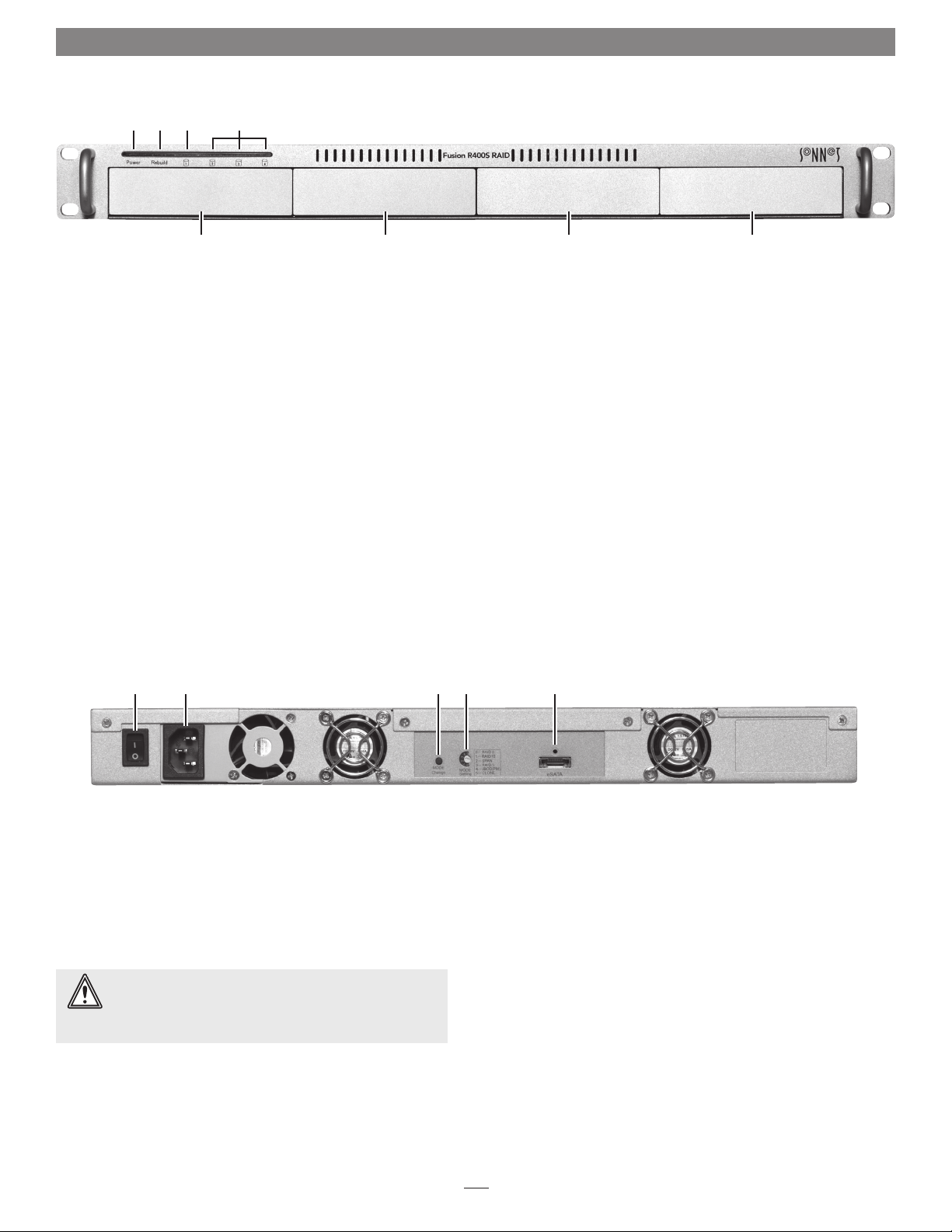
Fusion R400S RAID Features
➊ ➋ ➍➌
➎
1 – Power Indicator LED
This blue LED lights when the Fusion R400S RAID is
powered
2 – Rebuild Indicator LED
This orange LED lights when the Fusion R400S RAID is
rebuilding the data on a RAID 5 or 10 RAID set, or cloning
one drive to another drive when the system is set to Clone
mode
3 – Mode Change Confirmation; Drive 1 Presence, Activity,
and Fault Indicator LED
This LED lights red when the Drive Mode Change Switch is
pressed for more than three seconds. It also indicates Drive
1’s ready state (solid green), read and write activity (flashes
green), and fault status (OFF). Note that the LED will remain
off if the drive in drive bay 1 is not recognized
➎ ➎ ➎
➏ ➐ ➑ ➒ ➓
4 – Presence, Activity, and Fault Indicator LEDs for
Drives 2 – 4
These LEDs indicate the ready state (solid green), read and
write activity (flashes green), and fault status (OFF) for drives
2 – 4. Note that an LED will remain off if the corresponding
drive is not recognized
5 – Drive Modules
To remove a drive module, press its handle in until it pops
out, then pull out the entire module. To insert a drive
module, insert it into the drive bay until it stops, and then
push its handle in until it latches closed
6 – Power Button
7 – Power Cord Socket
8 – Drive Mode Change Switch
Press and hold this switch for three or more seconds to
activate the selected drive mode
WARNING: Once you press and hold the Mode Change
Switch for more than three seconds while the R400S RAID
is powered, any files stored on the system are lost and cannot be
recovered!
9 – Drive Mode Setting Switch
Select the drive mode setting using this switch
10 – Locking eSATA Interface Port
This port is compatible with the included Sonnet locking
eSATA data cable and standard eSATA data cables as well
1
Page 4
Drive Installation and Enclosure Setup
1. Remove the Fusion R400S RAID from its packaging, and place it
on a flat, level surface.
2. If you intend to use the Fusion enclosure in a rack, install the
Sonnet rack slide set (or equivalent), sold separately:
• FUS-RSS-P for 17–21.5" deep racks
• FUS-RSS-S for 23–26.5" deep racks
• FUS-RSS for 27–30.5" deep racks
• FUS-RSS-L for 29–32.5" deep racks
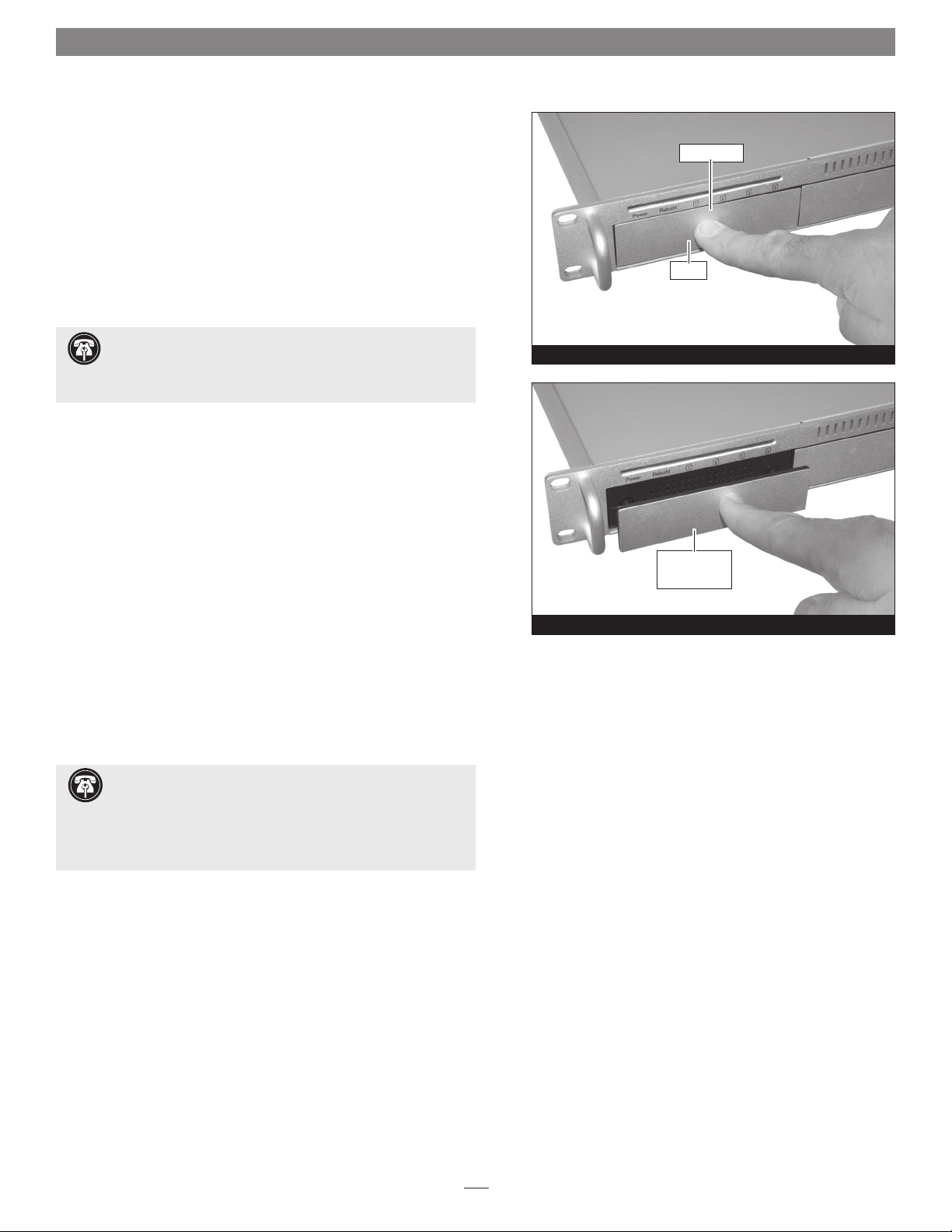
drive module
Push in
Support Note: It is possible that the drive modules may have
shifted during shipping. To ensure good connections between
the drives and their connectors, remove and reinstall each drive module
before powering on the enclosure.
3. Push in the drive module’s handle until it pops out (Figure 1).
Pull the handle toward you to slide out and remove the drive
module.
4. Carefully slide the drive module back into the enclosure until it
stops, and then push the handle in until it clicks to secure the
drive module inside the enclosure (Figure 2).
5. Repeat steps 3 and 4 for the remaining drives.
6. Install the Fusion R400S RAID into the rack or set it on the
surface which it will reside.
Connect Fusion R400S RAID to Computer and Power
Outlet
1. Using the supplied locking eSATA cable, connect the Fusion
R400S RAID to your computer.
Support Note: The supplied Sonnet locking eSATA cable is
compatible with all eSATA ports and provides a far more
secure connection when used with Sonnet drive enclosures and host
controller cards with the matching port. If necessary, you may remove
the locking mechanism from the connector by removing the screws
securing the two halves.
Figure 1
push handle in
until it clicks
Figure 2
2. Connect the supplied power cable between the Fusion R400S
RAID and a grounded wall outlet or power strip; verify the cable
is plugged in securely.
2
Page 5

Drive Mode Selection Instructions
General Information
The drives included with Fusion R400S RAID are configured
as a RAID 5 group and Mac OS Extended-formatted. The
following information may help you to decide whether you
need to reformat the drives:
®
• OS X
users wishing to use the Fusion R400S RAID as
configured may start using the product immediately; the
drives will appear on the desktop as a single volume.
• OS X users wishing to use the R400S RAID in another
mode (RAID 0, RAID 10, etc.) must change the mode
following the directions below, and then format the drives
as described on the next page.
• Windows
®
and Linux® users must select the mode
following the directions below, and then format the drives
as described on the next two pages.
Support Notes: For more information on the drive
configuration modes you may choose from on the
R400S RAID, skip to page 7.
If you wish to configure the drives in JBOD mode, your
eSATA controller MUST support port multiplier functionality,
otherwise, only one drive will appear to the system.
Select Drive Mode
WARNING: Reconfiguring the drives in your Fusion
R400S RAID enclosure requires you to reformat them.
Reformatting the drives will erase any data on them ! If
there is any data on them, back it up before configuring the
drives.
1. Power up the Fusion R400S RAID enclosure.
2. If the R400S RAID is connected to a Windows or Linux
computer, skip to the next step. If the R400S RAID is
connected to a Mac
the desktop, and then eject it (select the drive, and then
press command+E, or drag the icon to the eject icon in
the dock).
®
, wait until the drive mounts to
Figure 3
LED Operation — Drive Mode Selection
LED lights RED
to indicate mode
Power Rebuild
change button
pressed
1 2 3 4
Figure 4
LEDs tur n on
3. Using a small screwdriver, turn the MODE Setting
switch on the back of the enclosure to the position that
matches the mode you wish to use (Figure 3).
4. Press and hold the MODE Change switch for more than
three seconds (Figure 3); the Drive 1 LED will light red,
while the LEDs for Drives 2 – 4 will light green until
you release the button (Figure 4). Once you release the
button, all four drive LEDs will flash green as the mode
change takes place.
5. Turn on your computer (or restart it if it was already on);
you may now format the drives using your computer’s
operating system drive formatting application; go to the
next page.
3
Page 6

OS Formatting Instructions
OS X Users’ Instructions
1. After changing the disk mode and turning on or restarting
your computer, a Disk Insertion window will appear stating
that there is an unreadable volume; click Initialize, and then
Disk Utility will open.
2. In the Disk Utility window, the RAID group will appear as a
single volume (or four volumes if the drive mode was set to
JBOD). Select the volume, and then click the Erase tab at the
top of the window.
3. Type in a name for the volume, and then click Erase; a
window will appear asking you to approve your choice.
4. Click Erase; the Fusion R400S RAID volume will appear on
your computer’s desktop.
5. If the drives were configured in any mode other than JBOD,
skip to the next step. If the drives were configured in JBOD
mode, repeat steps 2 – 4 for the remaining three drives.
5. Close Disk Utility; the Fusion R400S RAID is ready for use.
Windows 8/7/Vista/Server 2008 Users’ Instructions
1. Click Start, then right-click Computer, and then click Manage.
9. When the Format Partition window appears, enter a new
name for the volume, select “Perform a quick format”, and
then click Next.
Note: If you do not select the quick format option, this process will take
much longer to complete.
10. If the drives were configured in any mode other than JBOD,
when the next window appears, click Finish; once “Healthy
(Primary Partition)” appears, the R400S RAID is ready for use.
If the drives were configured in JBOD mode, repeat steps 4 –
10 with the remaining three drives.
Windows XP/Server 2003 Users’ Instructions
Support Note for Windows XP Users: Windows XP
32-bit does not support volumes greater than 2TB.
Windows XP x64, Windows Vista Ultimate/Enterprise (32- bit
and 64-bit editions), and Windows Server 2003 support volumes
greater than 2TB, but must be formatted using the GPT file system,
which is not accessible by Windows XP 32-bit systems.
1. Select Computer Management From the Windows Start menu.
If it is not available in the Start Menu, select Start > Settings >
Control Panel > Administrative Tools. In the Administrative
Tools window, double-click Computer Management.
2. In the Computer Management window, click Storage in the
left pane to expand the list (if necessary), and then click Disk
Management.
3. If you are using Windows Vista, an Initialize Disk window will
appear; skip to step 4. If you are using Windows 8, 7, or Server
2008, when the disks are displayed, the R400S RAID’s drives
will appear as a single volume when configured in any mode
other than JBOD (or as four drives if configured as JBOD),
and listed as “unallocated”. Right-click where the words “Not
Initialized” appear and select Initialize Disk.
4. In the Initialize Disk window, select GPT, and then Click OK.
5. Back in the Computer Management window, right-click where
the word “Unallocated” appears, and then select New Simple
Volume.
6. When the New Simple Volume Wizard window appears, click
Next.
7. When the Specify Volume Size window appears, click Next if
you want all of the R400S RAID’s capacity to remain as one
block (volume). Otherwise, adjust the volume size to meet
your needs, and then click Next.
8. When the Assign Drive Letter or Path window appears, select
Assign the following drive letter, choose a letter, and then
click Next.
2. In the Computer Management window, click Storage on the
left, and then double-click Disk Management.
3. When the Initialize and Convert window appears, click OK.
4. When the Select Disks to Initialize window appears, select the
RAID volume or individual drive, and then click Next.
5. When the next window appears, click Finish.
6. In the Disk Management window, the Fusion R400S RAID’s
RAID group will appear (listed as “unallocated”) as a single
volume, or as four volumes if the drives were configured
in JBOD mode. Right-click where the word “unallocated”
appears, and then select New Partition.
7. When the Welcome to the New Partition Wizard window
appears, click Next.
8. When the Select Partition Type window appears, select Primary
Partition, and then click Next.
9. When the Specify Partition Size window appears, click next.
10. When the Assign Drive Letter or Path window appears, select
Assign the following drive letter, choose a letter, and then
click Next.
4
Page 7

Drive Mode Selection and OS Formatting
11. When the Format Partition window appears, enter a new
name for the volume table if you’d like. Select Perform a quick
format, and then click Next.
12. When the next window appears, click Finish.
Note: If you do not select the quick format option, this process will take
much longer to complete.
13. If the drives were configured in any mode other than JBOD,
once the RAID group has been formatted and finishes
building, it is ready to use. If the drives were configured in
JBOD mode, repeat steps 4 – 12 with the remaining three
drives.
Linux Users’s Information
For Linux drive formatting information, please contact your
Linux/Unix vendor.
5
Page 8

Status LED Indications
System Powered, No Data Reads or Writes
When the Fusion R400S RAID is powered on, and no data
is being written or read, the Power and Drive LEDs turn on
(Figure 5).
Drive Activity
When data is being read from or written to a drive, its
corresponding LED will flash during read and write activity
(Figure 6).
Drive Not Recognized
When one or more drive LEDs is off while the others
remain lit, the corresponding drive(s) is not recognized
(Figure 7). There are a few possible causes for a drive to not
be recognized, including: the corresponding drive module is
not plugged securely into the enclosure or the drive itself has
failed. There is a small chance that the enclosure is defective.
System Powered, No Data Reads or Writes
LEDs st ay on
Power Rebuild
1 2 3 4
Figure 5
Drive Activity (Data Reads and Writes)
LEDs flash
Power Rebuild
1 2 3 4
Figure 6
Drive Not Recognized
LEDs flash or st ay on LED stays off
Clone, RAID 5, or RAID 10 Rebuild
After inserting a drive into the R400S RAID enclosure to
replace a failed drive from a RAID 5 or RAID 10 group (or
putting in a new drive to be cloned to), the Rebuild LED
lights up orange, and the Drive LEDs flash with activity
until the RAID has been rebuilt or the clone copy completed
(Figure 8). Once the rebuild is complete, the Rebuild LED
turns off.
Power Rebuild
1 2 3 4
Figure 7
Clone, RAID 5, or RAID 10 Rebuild
LED stays on
Power Rebuild
1 2 3 4
Figure 8
LEDs flash
6
Page 9

Drive Mode Descriptions
WARNING: RAID 5 and 10 formatting improves
data accessibility and reliability during normal
operations, however, you still need a good backup strategy
for long-term protection of your data.
To configure the Fusion R400S RAID’s drives, refer to Select
Drive Mode on page 5.
The following pages describe the drive configuration modes
supported by this Sonnet product.
RAID 0: Striping, No Redundancy
RAID 0 (striping) is based on the fact that increased
performance can be achieved by simultaneously accessing
data across multiple drives, increasing data transfer rates
while reducing average access time by overlapping drive
seeks. Drives are accessed alternately, as if stacked one on
top of the other. RAID 0 provides no data protection, but
offers the full capacity of the drives. If one drive fails, all
data within that stripe set is lost. See Figure 9.
Stripe 1
Stripe 2
Stripe 3
RAID 0: Striping, No Redundancy
Disk 1
Disk 2Disk 3Disk 4
Figure 9
RAID Level 0 is used by applications requiring high
performance for non-critical data.
RAID 10: Striping, Mirror Spans Two Drives
RAID 10 increases data transfer rates while ensuring security
by writing the exact same data simultaneously to two
or more different drives. RAID 10 is used in applications
requiring higher performance and redundancy, combining
the attributes of RAID Levels 1 and 0. See Fig ure 10.
RAID 10 offer 50% of the total capacity of the four drives.
Span: Concatenation, Volume Spans Four Drives
Span mode creates a single, large volume that spans all four
drives, writing files to the capacity of the first drive, then the
second drive, and so on. See Figure 11. Span mode provides
no data protection.
Span formatting offers the full capacity of the four drives.
Stripe 1
Stripe 2
Stripe 3
RAID 10:
Striping, Mirror Spans Two Drives
Disk 1
Data 1
Data 3
Data 5
Span (Concatenation, Big)
Disk 1
Data 1
Data 2
Disk 2
Data 1
Data 1
Data 3
Data 3
Data 5
Data 5
Disk 2
Data 25
Data 26
Figure 10
Disk 3
Data 49
Data 50
Disk 3
Data 2
Data 4
Data 6
Disk 4
Data 73
Data 74
Disk 4
Data 2
Data 2
Data 4
Data 4
Data 6
Data 6
Data 3
Data 4
7
Data 27
Data 28
Figure 11
Data 51
Data 52
Data 75
Data 76
Page 10

Drive Mode Descriptions
RAID 5: Striping, Parity Distributed Among Drives
RAID 5 increases reliability while using fewer drives than
mirroring by using parity redundancy: parity is distributed
across multiple drives. Any one of the four drives can fail,
and the volume will continue to function. See Figure 12.
RAID 5 formatting offers 75% capacity of the four drives’
total capacity. For instance, if your system has four 2TB
drives, the total unformatted capacity is 8TB. After RAID 5
formatting, approximately 6TB is available for storage, with
the other 2TB used for parity.
RAID 5:
Striping, Parity Distributed Among Drives
Stripe 1
Stripe 2
Disk 1
Data 1
Data 5
Disk 2
Data 2
Data 6
Disk 3
Data 3
Parity 4–6
Disk 4
Parity 1–3
Data 4
JBOD (PM): Just a Bunch of Disks
JBOD configuration enables all four individual drives to
be available for normal storage operations with no special
data protection by combining several drives into one
large drive. See Fig ure 13. Note that for JBOD operation,
the R400S RAID requires the use of an eSATA controller
that offers port multiplier support; refer to the eSATA
controller’s documentation or the manufacturer’s Website
for information. If you format the drives as JBOD and use
the R400S RAID with an eSATA controller with no port
multiplier support, only one of the four drives will be
accessible. JBOD provides no data protection.
JBOD offers the full capacity of each of the drives.
Stripe 3
Stripe 4
Data 9
Parity
10–12
Parity 7–9
Data 10
Figure 12
Data 7
Data 11
JBOD (Just a Bunch of Disks)
Disk 1
Data 1
Data 2
Data 3
Data 4
Disk 2
Data 5
Data 6
Data 7
Data 8
Disk 3
Data 9
Data 10
Data 11
Data 12
Data 8
Data 12
Disk 4
Data 13
Data 14
Data 15
Data 16
Clone: Data Mirrored on All Four Drives
Clone mode enables all four drives to store the same files.
You may remove one of the four drives and replace it with
another drive; the data will be copied without further action
from you. Depending on the capacity of the drives you’ve
installed, this process may take hours to complete.
Figure 13
Clone (Data Mirrored on All Drives)
Disk 1
Data 1
Data 2
Data 3
Data 4
8
Disk 2
Data 1
Data 2
Data 3
Data 4
Disk 3
Data 1
Data 2
Data 3
Data 4
Figure 14
Disk 4
Data 1
Data 2
Data 3
Data 4
Page 11

Tips and Additional Information
Specifications
Compatibility Compatible with Mac,
Windows, and Linux computers
with an eSATA interface
External Connector One locking eSATA
Data Transfer Speed Up to 240 MB/s, depending
on interface used and drive
configuration
OS Support Platform independent
Supported Drive
Configurations
Power Supply Universal 220W, 100–240V AC,
Operating Temperature 32 to 104˚ F (0˚ C to +40˚ C)
Dimensions (WxDxH) 17.0 x 16.25 x 1.75 in.
Weight (with drives,
approximate)
RoHS Compliant Yes
Package Contents • Rackmount disk enclosure
1. JBOD operation requires the use of an eSATA controller with
port multiplier support.
Hardware-based RAID 0, 5, and
10; span, clone, and JBOD
50– 60Hz
(43.2 x 41.3 x 4.4 cm)
20.2 lbs (9,16 kg)
• Four 3.5" drive trays drive
modules
• One locking eSATA data cable
• Power cord
• User's guide
(1)
SAFET Y PRECAUTIONS
Please read this section carefully before proceeding. These
precautions explain the correct and safe use of this device,
thereby helping to prevent injury to you or others, and also help
you to minimize the risk of damaging the device.
Warnings
Always follow the basic warnings listed here to avoid the risk of
serious injury or death from electrical shock, short-circuiting, fire,
and other hazards. These warnings include, but are not limited to:
• Follow the instructions in this manual carefully; contact your
reseller or local distributor for additional advice not covered in
this User’s Guide.
Contacting Sonnet Customer Service
USA Customers
The Sonnet Web site located at www.sonnettech.com has the
most current support information and technical updates. Before
you call Sonnet Customer Service, please check our Web site for
the latest updates and online support files, and check this User’s
Guide for helpful information. When you call Sonnet Customer
Service, have the following information available so our customer
service staff can better assist you:
• Product name
• Date and place of purchase
• Hard drive model(s)
• Computer model
• Operating system
• Software/firmware versions
If further assistance is needed, please contact Sonnet Customer
Service at:
Online Service Form: http://serviceform.sonnettech.com
Tel : 1-949-472-2772
(Monday–Friday, 7 a.m.–4 p.m. Pacific Time)
E-mail: support@sonnettech.com
For Customers Outside the USA
For support on this product, contact your reseller or local
distributor.
Visit Our Web Site
For the most current product information and online support
files, visit the Sonnet Web site at www.sonnettech.com/support/.
Register your product online at http://registration.sonnettech.
com to be informed of future upgrades and product releases.
• With the exception of the user-swappable parts, do not attempt
to disassemble or modify the enclosure. If this device appears to
be malfunctioning, contact your reseller or local distributor.
• Do not drop the enclosure; dropping or mishandling of the
enclosure or adapter card may result in a malfunction leaving
the product inoperable.
• Do not expose the device to rain, use it near water or containers
that contain liquids which might spill into any openings, or in
damp or wet conditions.
• If unusual smells, sounds, or smoke come from the device, or if
liquids enter it, switch it off immediately and unplug it from the
electrical outlet.
9
Page 12

©2012 Sonnet Technologies, Inc. All rights reserved. Sonnet, the Sonnet logotype, Simply Fast, the Simply Fast logotype, Creativity Stored Here, and Fusion are trademarks of Sonnet Technologies, Inc. Mac, the Mac logo, Mac
OS, and OS X are trademarks of Apple Inc., registered in the United States and other countries. Other product names are trademarks of their respective owners. Product specifications subject to change without notice.
Printed in the USA. UG-FUS-R4SR5-WD-E-A-121212
 Loading...