

Page 1

Sonnet eSATA Extender
SATA-to-eSATA Extension Cable for Mac
Installation Instructions for eSATA Extender
®
Pro
You Should Have
The following items should be included in your product package:
• One Sonnet eSATA SATA-to-eSATA extension cable
The following items may be required for installation:
• Medium Phillips screwdriver (magnetic tip suggested)
• Flexible metal putty knife (for use in pre-2008 Mac Pro
installations)
System Requirements
The Sonnet eSATA Extender requires the following in order to
install into your system:
• One available PCI Express (PCIe) slot back panel opening
Usage Information
Connecting drives:
•
You must power on and connect drive enclosures to the Sonnet eSATA
Extender before you turn on your computer. Your computer will
not recognize the drives if you connect them or power on the
enclosures after startup.
How to Identify Which Mac Pro You Have
The Sonnet eSATA Extender works in all Mac Pro computers,
but the installation procedure differs based on the design. The
installation instructions section of this document is broken into
two sections; instructions for the original Mac Pro design (pre-
2008) and the current model (Early 2008).
The simplest way to identify which model you have is to look
at the memory riser cards (where the RAM is installed). In pre2008 Mac Pro computers, the memory riser card components are
oriented the same direction (see Figure 6 on page 3), while in
Early 2008 Mac Pro computers, the components are oriented in
opposite directions (see Figure 30 on page 11).
Instructions for pre-2008 Mac Pro start on the next page;
instructions for Early 2008 Mac Pro start on page 10.
Disconnecting drives:
•
You must shut down your computer before you power off or disconnect
drive enclosures from the Sonnet eSATA Extender. Your computer will
not recognize the drives if you connect them or power on the
enclosures after startup.
This product does not support drive enclosures with port multipliers.
•
The Sonnet eSATA Extender merely enables you to connect
additional hard disk drives to the Mac Pro’s logic board, which
does not support multipliers. Use only enclosures with direct
connections (one eSATA cable per drive).
Swapping drives:
•
This product does not support drive hot-swapping or hot-plugging.
The Mac Pro’s logic board does not support drive swapping; you
must shut down the computer before changing drives.
Remember to register your product online at http://registration.sonnettech.com to be informed of future upgrades and product releases.
Software updates and links are available from the Sonnet web site at www.sonnettech.com. • Online support form available at http://supportform.sonnettech.com.
Sonnet Technologies Customer Service hours are Mon.-Fri., 7 a.m.–4 p.m. Pacific Time • Customer Service Phone: 1-949-472-2772 • E-mail: support@sonnettech.com
Sonnet Technologies, Inc., 8 Autry, Irvine, California 92618 USA • Tel: 1-949-587-3500 Fax: 1-949-457-6350
©2008 Sonnet Technologies, All rights reserved. Sonnet, the Sonnet logotype, Simply Fast, and the Simply Fast logotype are trademarks of Sonnet Technologies, Inc. Macintosh and Mac are trademarks of Apple Inc., registered in
the United States and other countries. Other product names are trademarks of their respective owners. Product specifications subject to change without notice. Printed in the USA. QS-TCB-SATA-MP-E-A-061208
Powering Off drives:
•
DO NOT power off a drive connected to the Sonnet eSATA Extender
while the computer is on, even if you have “ejected” it (selected Eject
from a menu or dragged the drive to the eject icon in the dock). Your
computer may experience a kernel panic.
Identifying drives connected to the Sonnet eSATA Extender:
•
System Profiler and Disk Utility identify drives connected to the
eSATA Extender as internal drives, but do not assign them bay
numbers. However, Disk Utility will identify the drives as “Drive
4” and “Drive 5”; drives mounted in the computer are assigned
numbers 0–3.
Page 2
PRE-2008 MAC PRO INSTALLATION
Shut Down and Open Computer
1. Shut down your Mac Pro. If the computer has been
on for a while, allow a five to ten minutes for it to
completely cool before beginning the installation.
2. If you need to move the computer to a different area
where you can work freely, disconnect any connected
cables, move the computer, then reconnect the power
cord to the computer and an electrical outlet.
3. Touch the top of the computer to discharge any
potentially damaging static electricity.
Support Note: To avoid generating a static charge in
your body, do not walk around the room until after
you finish installing the eSATA extender and close the computer.
4. Disconnect the power cord, and if necessary, any
remaining cables, from the computer.
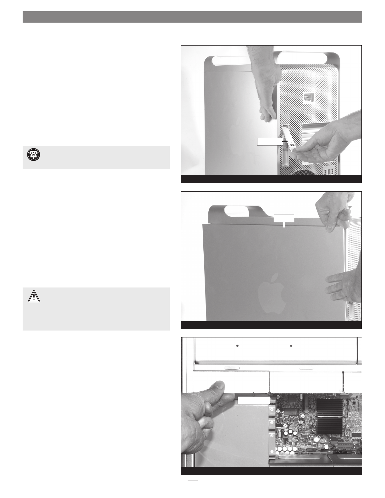
5. While supporting the side panel, lift up the locking
latch on the back of the computer (Figure 1).
Pull out the top of the side panel, and lift it up and
6.
away from the computer (Figure 2). Set aside the side
panel.
locking latch
locking latch
side panel
Figure 1
side panel
7. With the front of the computer facing left, lay the Mac
Pro down on a soft, clean towel or blanket on top of
your work surface.
WARNING: When handling computer products, take
care to prevent components from being damaged
by static electricity; avoid working in carpeted areas. Handle
processor upgrade cards only by their edges and avoid
touching connector traces and component pins. Also, avoid
touching the logic board and any of its components.
Remove Parts to Access Logic Board’s SATA
Connectors
1. Remove the left two hard drive carriers (1 and 2) from
the computer’s drive bays (Figure 3). Note: Make sure
the locking latch on the back of the computer is in the
open position before attempting to remove the carriers.
hard drive carrier
Figure 2
hard drive carrier
Figure 3
2
Page 3
PRE-2008 MAC PRO INSTALLATION
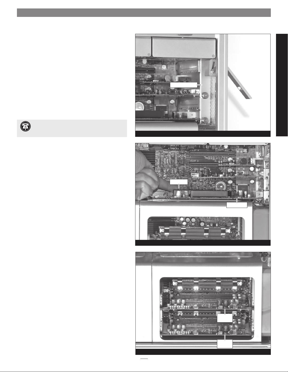
2. Unscrew the PCI bracket retainer’s captive screws, and
then remove the retainer and set it aside (Figure 4).
PCI bracket retainer
Support Note: If your computer’s graphics card has a
separate power cable, disconnect it before proceeding to
the next step.
3. While pulling the PCIe slot release tab, carefully
remove the graphics card from the computer, handling
it only by its edges (Figure 5). Set aside the graphics card
with the heat sink (or fan) face down. Please note that if
your computer has any full length PCIe cards installed (long
enough to extend all the way to the fan assembly), you must
also remove them before proceeding to the next step.
4. Grasping it by its finger holes, gently but firmly pull
on the top memory riser card to remove it from the
computer (Figure 6), and then set it aside on a soft,
clean cloth with the DIMMs facing up. Repeat the
process with the bottom memory riser card.
PRE-2008 MAC PRO INSTALLATION
Figure 4
release tab
graphics card
Figure 5
memory
riser card
memory
riser card
Figure 6
3
Page 4
PRE-2008 MAC PRO INSTALLATION
WARNING: Some early-production, pre-2008 Mac
Pro computers were assembled with threadlocker (e.g.
LocTite®) applied incorrectly to the two screws that secure
the memory riser card compartment to standoffs attached to
the bottom of the computer. If the bottom screws continue
to turn without loosening when you attempt to remove
them, stop! Contact Sonnet Customer Support for further
assistance.
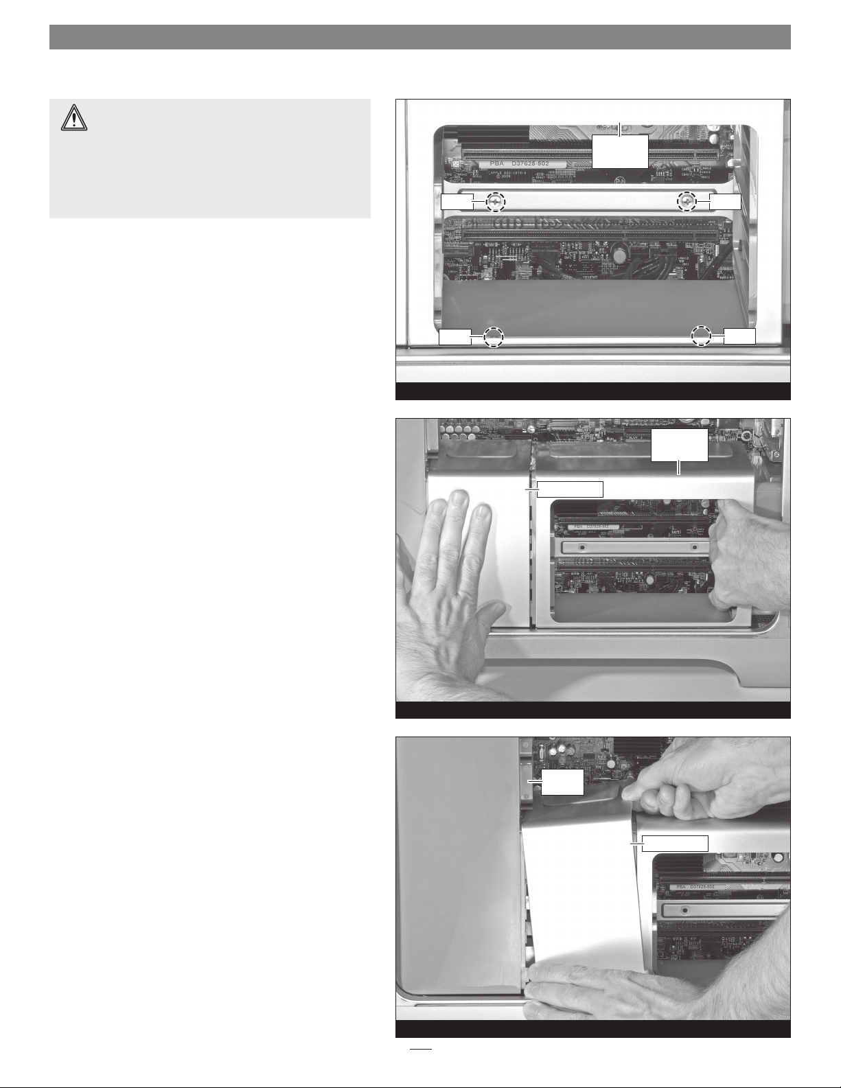
5. Locate and remove the four screws securing the memory
riser card compartment to the rest of the computer
(Figure 7).
memory
riser card
compartment
screwscrew
6. Slide the memory riser card compartment about 1/8 inch
(3mm) to the right to disengage it from the heat sink
cover (Figure 8).
screw
Figure 7
heat sink cover
Figure 8
memory
riser card
compartment
screw
7. Carefully lift up the right edge of the heat sink cover
and rotate it slightly as shown to disengage it from the
fan assembly (Figure 9). Pull the cover away from the
fan assembly, remove it, and then set it aside.
fan
assembly
heat sink cover
Figure 9
4
Page 5
PRE-2008 MAC PRO INSTALLATION
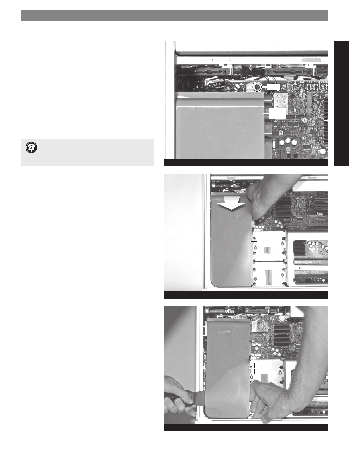
8. Locate and remove the screw securing the top of the fan
assembly to the logic board (Figure 10).
Support Note: The fan assembly is plugged in
directly to the logic board, and secured to the bottom
of the computer by guide rails. When removing the assembly,
it is important to pull it straight up.
9. To disconnect its connector from the logic board,
gently, but firmly pull the top of the fan assembly
toward you until you feel the connectors separate
(Figure 11).
Figure 10
screw
fan
assembly
PRE-2008 MAC PRO INSTALLATION
10. Using a putty knife to assist, pull the fan assembly
straight up out of the computer (Figure 12). Please note
that you may need to rock the fan assembly a bit in
order to loosen it from the guide rails.
Figure 11
fan
assembly
fan
assembly
Figure 12
5
Page 6

PRE-2008 MAC PRO INSTALLATION
Install eSATA Extender
1. Locate the two SATA connectors in the upper left corner
of the logic board labeled “ODD_SATA” (Figure 13).
2. Connect the eSATA Extender’s cables to the SATA
connectors on the logic board, plugging in the straight
connector on the top, the angled connector on the
bottom; verify the connectors are plugged in securely
(Figure 14)
.
logic board
SATA connectors
Figure 13
3. Locate an available PCI Express slot inside your computer
and remove its access cover. If your Mac Pro is equipped
with a thin graphics card, you may be able to use the
empty space above the slot it occupies.
4. Insert the eSATA connector bracket into the open space
(Figure 15).
straight connector
angled connector
Figure 14
eSATA
connectors
bracket
Figure 15
6
Page 7

PRE-2008 MAC PRO INSTALLATION
Reassemble Computer
1. Insert the bottom of the fan assembly into the guides
in the bottom of the computer case, and then slide the
assembly in part way. Route the top eSATA Extender
cable through the notch in the assembly, and then push
the assembly all the way in until the connectors are
connected; verify the connector is plugged in securely
(Figure 16).
2. Secure the fan assembly to the logic board with the
screw you removed previously (Figure 17).
notch
top cable
fan assembly
PRE-2008 MAC PRO INSTALLATION
Figure 16
3. Insert the edge of the heat sink cover under the top tab
on the fan assembly, and then rotate the cover down so
that the tabs on the fan assembly and cover join together
(Figure 18).
screw
fan assembly
Figure 17
top tab
heat sink cover
fan assembly
Figure 18
7
Page 8

PRE-2008 MAC PRO INSTALLATION
4. Slide the memory riser card compartment to the left
so that the tabs on the compartment and the heat sink
cover join together (Figure 19).
5. Move the memory riser card compartment so that the
screw holes in it, and on the logic board and computer
case line up.
6. Secure the memory riser card compartment using the
screws you removed previously; do not overtighten the
screws (Figure 20).
Figure 19
riser card
compartment
heat sink cover
memory
memory
riser card
compartment
screwscrew
7. Handling them by their edges, insert the memory riser
cards back into their slots; make sure the cards are
fully seated (Figure 21).
screw
Figure 20
Figure 21
memory
riser card
memory
riser card
screw
8
Page 9

PRE-2008 MAC PRO INSTALLATION
8. Handling it by its edges, install the graphics card into its
slot; make sure the card is fully seated (Figure 22). If
you disconnected a power cable from the graphics card
when you disassembled the computer, connect it now.
9. Install any full-length PCIe cards you removed when you
disassembled the computer.
10. Secure the PCI Express cards with the PCI bracket
retainer, turning the captive screws finger-tight
(Figure 23)
.
11. Carefully insert the hard drive carriers back into the
drive bays, making sure any attached drives are plugged
in securely (Figure 24).
graphics card
PRE-2008 MAC PRO INSTALLATION
Figure 22
PCI bracket retainer
Figure 23
12. Lift the Mac Pro back into the upright position, and
then insert the side panel back into place.
13. While supporting the side panel, press down on the
locking latch to secure the panel in place.
14. Reconnect your computer and turn it on to verify
everything is working properly. If everything works
properly, your installation is complete.
hard drive carrier
Figure 24
9
Page 10

EARLY 2008 MAC PRO INSTALLATION
Shut Down and Open Computer
1. Shut down your Mac Pro. If the computer has been
on for a while, allow a five to ten minutes for it to
completely cool before beginning the installation.
2. If you need to move the computer to a different area
where you can work freely, disconnect any connected
cables, move the computer, then reconnect the power
cord to the computer and an electrical outlet.
3. Touch the top of the computer to discharge any
potentially damaging static electricity.
Support Note: To avoid generating a static charge in
your body, do not walk around the room until after
you finish installing the eSATA extender and close the computer.
4. Disconnect the power cord, and if necessary, any
remaining cables, from the computer.
5. While supporting the side panel, lift up the locking
latch on the back of the computer (Figure 25).
Pull out the top of the side panel, and lift it up and
6.
away from the computer (Figure 26). Set aside the side
panel.
locking latch
side panel
Figure 25
side panel
7. With the front of the computer facing left, lay the Mac
Pro down on a soft, clean towel or blanket on top of
your work surface.
WARNING: When handling computer products, take
care to prevent components from being damaged
by static electricity; avoid working in carpeted areas. Handle
processor upgrade cards only by their edges and avoid
touching connector traces and component pins. Also, avoid
touching the logic board and any of its components.
Remove Parts to Access Logic Board’s SATA
Connectors
1. Remove the left two hard drive carriers (1 and 2) from
the computer’s drive bays (Figure 27). Note: Make sure
the locking latch on the back of the computer is in the
open position before attempting to remove the carriers.
hard drive carrier
Figure 26
hard drive carrier
Figure 27
10
Page 11

EARLY 2008 MAC PRO INSTALLATION
2. Unscrew the PCI bracket retainer’s captive screws, and
then remove the retainer and set it aside (Figure 28).
Support Note: If your computer’s graphics card has a
separate power cable, disconnect it before proceeding to
the next step.
3. While pulling the PCIe slot release tab, carefully
remove the graphics card from the computer, handling
it only by its edges (Figure 29). Set aside the graphics
card with the heat sink (or fan) face down. Please note that
if your computer has any full length PCIe cards installed (long
enough to extend all the way to the fan assembly), you must
also remove them before proceeding to the next step.
PCI bracket retainer
Figure 28
release tab
Carefully lift up the back edge of the heat sink cover
4.
and pull it toward you; the cover will pop free from the
magnets securing it (Figure 30). Remove the cover, and
then set it aside.
fan
assembly
Figure 29
graphics card
EARLY 2008 MAC PRO INSTALLATION
heat sink cover
Figure 30
11
Page 12

EARLY 2008 MAC PRO INSTALLATION
5. Locate and remove the screw securing the top of the fan
assembly to the logic board (Figure 31).
Support Note: The fan assembly is plugged in
directly to the logic board, and secured to the bottom
of the computer by guide rails. When removing the assembly,
it is important to pull it straight up.
6. Locate and remove the screw securing the bottom of the
fan assembly to the logic board (Figure 32).
Figure 31
screw
fan
assembly
7. Pull the fan assembly straight out of the computer
(Figure 33).
fan
assembly
screw
Figure 32
fan
assembly
Figure 33
12
Page 13

EARLY 2008 MAC PRO INSTALLATION
Install eSATA Extender
1. Locate the two SATA connectors in the upper left corner
of the logic board labeled “ODD_SATA” (Figure 34).
2. Connect the eSATA Extender’s cables to the SATA
connectors on the logic board, plugging in the straight
connector on the top, the angled connector on the
bottom; verify the connectors are plugged in securely
(Figure 35)
.
logic board
SATA connectors
Figure 34
3. Locate an available PCI Express slot inside your computer
and remove its access cover. If your Mac Pro is equipped
with a thin graphics card, you may be able to use the
empty space above the slot it occupies.
4. Insert the eSATA connector bracket into the open space
(Figure 36).
straight connector
angled connector
Figure 35
eSATA
connectors
bracket
EARLY 2008 MAC PRO INSTALLATION
Figure 36
13
Page 14

EARLY 2008 MAC PRO INSTALLATION
Reassemble Computer
1. Insert the bottom of the fan assembly into the guides in
the bottom of the computer case and slide the assembly
in part way. Route the top eSATA Extender cable through
the notch in the assembly, and then push the assembly
in the rest of the way until the connectors are connected;
verify the connector is plugged in securely (Figure 37).
2. Secure the top of the fan assembly to the logic board
with the screw you removed previously (Figure 38).
notch
top cable
fan assembly
Figure 37
3. Secure the bottom of the fan assembly to the logic
board with the screw you removed previously
(Figure 39)
.
fan
assembly
screw
fan assembly
Figure 38
screw
Figure 39
14
Page 15

EARLY 2008 MAC PRO INSTALLATION
4. Replace the heat sink cover, making sure that its tabs
snap into the holes in the fan assembly and memory
riser card compartment (Figure 40).
. Handling it by its edges, install the graphics card into its
5
slot; make sure the card is fully seated (Figure 41). If
you disconnected a power cable from the graphics card
when you disassembled the computer, connect it now.
fan
assembly
Figure 40
compartment
heat sink cover
memory
riser card
6. Install any full-length PCIe cards you removed when you
disassembled the computer.
7. Secure the PCI Express cards with the PCI bracket
retainer, turning the captive screws finger-tight
(Figure 42)
.
Figure 41
PCI bracket retainer
graphics card
EARLY 2008 MAC PRO INSTALLATION
Figure 42
15
Page 16

EARLY 2008 MAC PRO INSTALLATION
8. Carefully insert the hard drive carriers back into the
drive bays, making sure any attached drives are plugged
in securely (Figure 43).
9. Lift the Mac Pro back into the upright position, and
then insert the side panel back into place.
10. While supporting the side panel, press down on the
locking latch to secure the panel in place.
11. Reconnect your computer and turn it on to verify
everything is working properly. If everything works
properly, your installation is complete.
hard drive carrier
Figure 43
16
 Loading...