

Page 1
User’s Guide
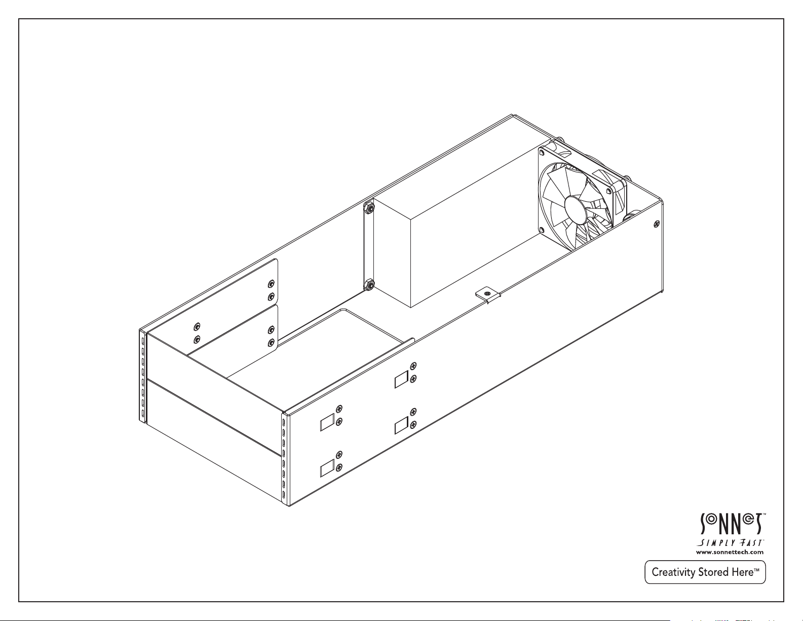
Mobile Rack Kit for Echo™ Express III-R
™
Rackmount Thunderbolt
Expansion Chassis
-to-PCIe Card
Page 2

Page 3

Contents
1 Introduction................................................................................................................................................................................ 1
2 Mobile Rack Kit Description......................................................................................................................................................... 2
3 Mobile Rack Kit and Device Installation Steps......................................................................................................................... 4
4 Specifications, Precautions, FCC Compliance, and Support Information...........................................................................................7
Specifications
Safety Precautions
FCC Compliance
Contacting Customer Service
Visit Our Website
Page 4

This page left intentionally blank
Page 5

Chapter 1 – Introduction
15.770
400.55
FRONT VIEW
6.320
160.53
REAR VIEW
SIDE VIEW
3.335
84.71
Congratulations on your purchase! With the Echo Express
III-R Mobile Rack Kit you can install one full-height or two
half-height 5.25" form factor mobile rack devices inside
your III-R’s enclosure. Some ideas including installing
an internal LTO-6 tape drive plus an enclosure for four
swappable 2.5" SSDs. An alternate configuration might
include a Sonnet Qio MR pro universal media reader.
Or, install one full-height mobile rack device, such as an
enclosure for three swappable 3.5" hard disk drives—now
you can add more devices to your rack without taking up
additional rack space.
The Mobile Rack Kit includes a 250W universal power
supply with numerous power connectors from which to
choose. Its internal fan works to keep things cool.
1
Page 6

Chapter 2 – Mobile Rack Kit Description
1 – Mobile Rack Cover Plates
These cover openings in the mobile rack kit where no
mobile rack device is installed.
2 – Power Supply
This provides power to installed mobile
rack devices and the fan. Shown
without attached wire harness.
3 – Cable Passthrough Opening
This enables you to route interface cables inside to connect to
installed devices.
4 – Power Switch
This turns power on and off to installed devices, works
independently from the Echo Express III-R chassis, and
must be switched manually (power supply remains on when
computer switched off or sleeps).
5 – Fan
This provides cooling for installed devices.
6 – Power Input Socket
Connect the included power cable here.
2
Page 7

Chapter 3 – Mobile Rack Kit and Device Installation Steps
1. Remove your Echo Express III-R Thunderbolt-to-PCIe card expansion
chassis from its packaging, or (after powering down and disconnecting
attached cables) from the rack into which it is installed. Set it on a flat,
level surface.
2. Using a Phillips screwdriver, remove and set aside the four screws
securing the Echo chassis’ inner assembly to its rackmount enclosure
(Figure 1).
3. Remove the inner assembly from the enclosure by gently gripping the
faceplate by its edges and pulling (Figure 1).
4. If you have not already done so, remove and set aside the six screws
securing the blank plate inside the enclosure, and then remove and
set aside the blank plate. (Figure 2).
.
Figure 1
Figure 2
3
Page 8
Chapter 3 – Mobile Rack Kit and Device Installation Steps
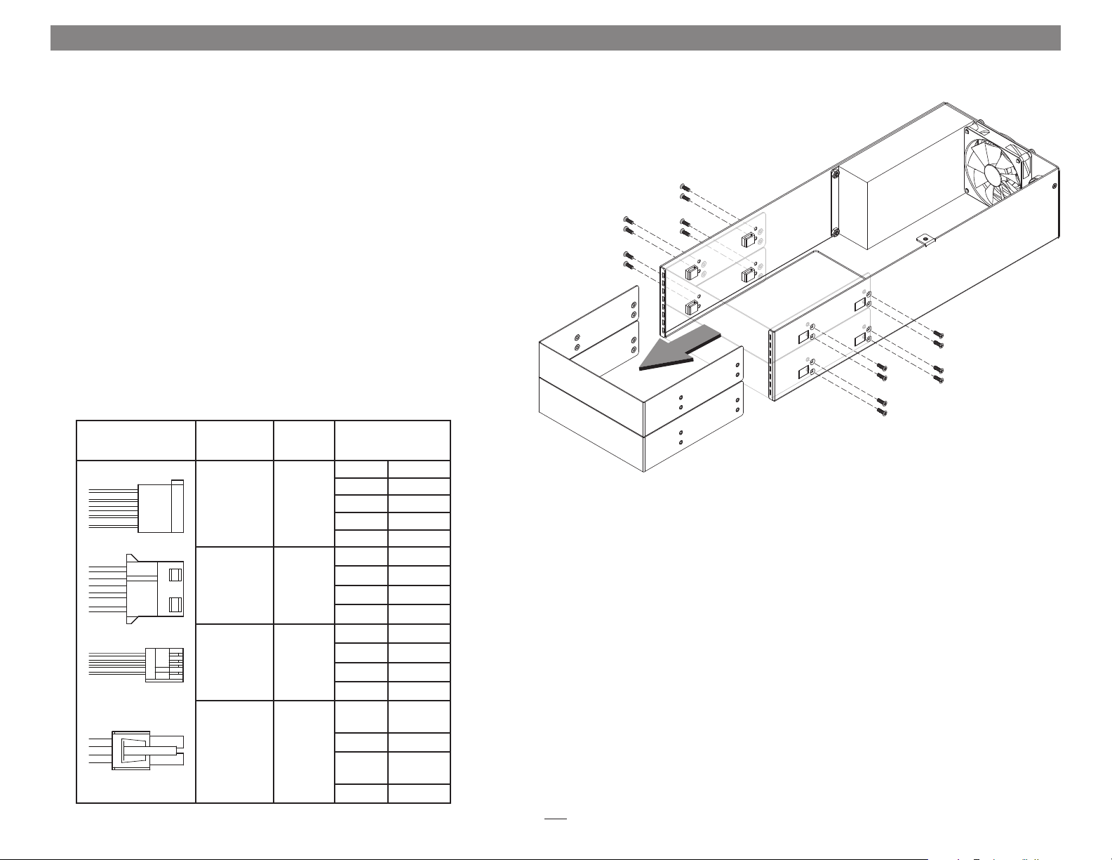
5. Remove the mobile rack kit from its packaging and set it on a flat, level
surface.
6. Remove and set aside the 16 screws securing the mobile rack cover
plates to the frame (Figure 3). Note that if you are installing a single
half-height device, you only need to remove the eight screws securing
one plate.
7. Set aside the unfastened mobile rack cover plate(s) (Figure 3).
8. Remove the mobile rack devices from their packaging, and then
configure them as necessary.
9. Route interface cables for the mobile rack devices you are installing
through the cable passthrough opening in the mobile rack kit’s frame.
10. Connect the interface cables and appropriate power connectors to the
mobile rack devices:
Connector
Type
Molex 8 8751
or equivalent
SATA
Molex 8981
or equivalent
AMP
171822-4 or
equivalent
Molex
39-01-2040
or equivalent
Quantity Wire
Yel low +12V
Ground
Black
2
3
1
2
Red +5V
Black Ground
Orange +3.3V
Yel low +12V
Black Ground
Black Ground
Red +5V
Yel low +12V
Black Ground
Black Ground
Red +5V
Yel low/
Yel low/
+12V
Black
Black Ground
+12V
Black
Black Ground
Figure 3
4
Page 9
Chapter 3 – Mobile Rack Kit and Device Installation Steps
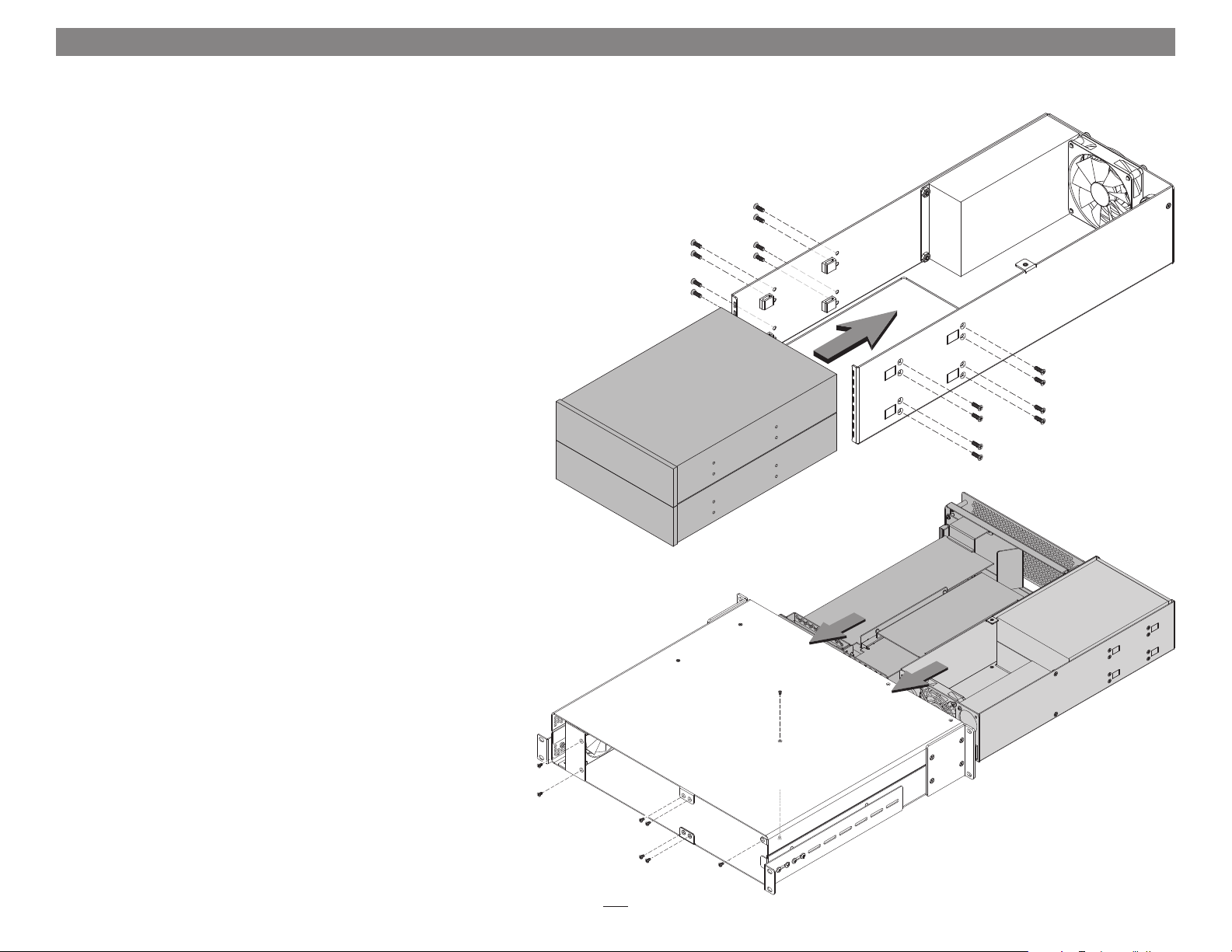
11. Insert the mobile rack devices into the mobile rack kit’s frame, and
then using the screws you removed previously, secure the devices to
the frame (Figure 4).
12. Arrange the cables and connectors inside the frame so as to ensure the
fan is not blocked.
13. If you have not already done so, install your PCIe cards in the Echo
chassis’ inner assembly (refer to steps 8 – 18 of the Echo Express III-R
user’s guide).
14 . Insert both the inner assembly and the mobile rack kit into the
Echo Express III-R rackmount enclosure (Figure 5). Secure the
inner assembly to the enclosure using the four screws you removed
previously. Secure the mobile rack kit to the enclosure using five of the
six screws you removed previously, as shown.
Figure 4
Figure 5
5
Page 10
Chapter 3 – Mobile Rack Kit and Device Installation Steps
15. Install the Echo Express III-R into its rack now.
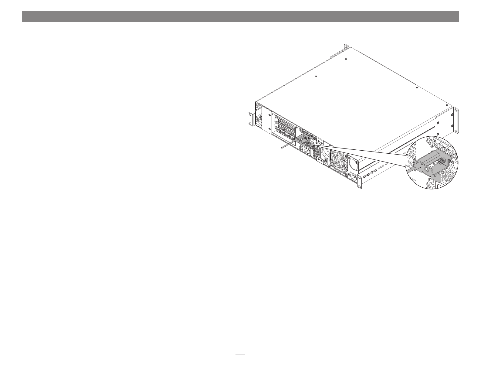
16. Connect a Thunderbolt cable between either Thunderbolt port on
the Echo chassis and a Thunderbolt port on your computer (or other
Thunderbolt device in the chain connected to the computer). If you
are daisy chaining additional Thunderbolt devices, connect another
Thunderbolt cable between the downstream device and the open
Thunderbolt port on the Echo chassis (Figure 6).
17. Using a Phillips screwdriver, secure the Thunderbolt cable(s) to
the Echo Express III-R with the supplied Thunderbolt cable lock
(Figure 6). Note that if you are using an optical Thunderbolt cable, the
supplied Thunderbolt cable lock is not compatible, and you should skip
to the next step.
18. Connect the included power cords between a wall outlet or power strip
and the Echo chassis’ power socket and the mobile rack kit’s power
socket. Note that the power indicator on the Echo Express III-R will not
light until the computer, and any other Thunderbolt device connected
between it and the Echo chassis, is powered on.
19. Connect interface cables between devices, PCIe cards, and computer as
necessary.
Figure 6
20. Return to Chapter 4 – Verify Connections Using System Information in the
Echo Express III-R User’s Guide to complete setup.
6
Page 11

Chapter 4 – Specifications, Precautions, FCC Compliance, and Support Information
Specifications
External Connectors Power (C14-type)
Internal Connectors • Two SATA power
• Three 4-pin peripheral
power
• One 4-pin floppy drive
power
• Two 4-pin CPU
Mobile Rack Devices
Supported
Power Supply Universal 250W, 100-240V
Operating Temperatures +32˚ F to +104˚ F
Dimensions WxDxH 6.32 x 15.77 x 3.33 in.
Weight 3.65 lbs
RoHS Compliant Yes
Package Contents • Echo Express III-R Mobile
• Two half-height mobile rack
devices up to 8" (20.3 cm)
long
or
• One full-height mobile rack
devices up to 8" (20.3 cm)
long
AC, 50-60 Hz
(0˚ C to +40˚ C)
(16.05 x 40.05 x 3.33 cm)
(1.65 kg)
Rack Kit
• Power Cord
• User’s Guide
SAFETY PRECAUTIONS
Please read this section carefully before proceeding.
These precautions explain the correct and safe use of this
device, thereby helping to prevent injury to you or others,
and also help you to minimize the risk of damaging the
device.
Warnings
Always follow the basic warnings listed here to avoid the
risk of serious injury or death from electrical shock, shortcircuiting, fire, and other hazards. These warnings include,
but are not limited to:
• Do not attempt to modify the enclosure. If this device
appears to be malfunctioning, contact your reseller or
local distributor
• Do not drop the enclosure; dropping or mishandling
chassis may result in a malfunction leaving the product
inoperable
• Do not insert your fingers or foreign objects inside the
power supply
• Do not expose the device to rain, use it near water or
containers that contain liquids which might spill into
any openings, or in damp or wet conditions
• If unusual smells, sounds, or smoke come from the
device, or if liquids enter it, switch it off immediately
and unplug it from the electrical outlet
• Follow the instructions in this manual carefully; contact
your reseller or local distributor for additional advice not
covered in this User’s Guide
FCC Compliance
Echo Express III-R Mobile Rack Kit complies with Part 15
of the FCC Rules. Operation is subject to the following two
conditions: This device may not cause harmful interference,
AND this device must accept any interference received,
including interference that may cause undesired operation.
Contacting Customer Service
The Sonnet Web site located at www.sonnettech.com
has the most current support information and technical
updates. Before you call Customer Service, please check
our Web site for the latest updates and online support files,
and check this User’s Guide for helpful information.
When you call Customer Service, have the following
information available so the customer service staff can
better assist you:
• Product name
• Date and place of purchase
• Computer model
• PCIe card models
• Mobile rack device models
• Operating system version
• Software/firmware versions
USA Customers
If further assistance is needed, please contact Sonnet
Customer Service at:
Tel : 1-949-472-2772
(Monday–Friday, 7 a.m.–4 p.m. Pacific Time)
E-mail: support@sonnettech.com
For Customers Outside the USA
For support on this product, contact your reseller or local
distributor.
Visit Our Web Site
For the most current product information and online
support files, visit the Sonnet Web site at www.sonnettech.
com/support/. Register your product online at http://
registration.sonnettech.com to be informed of future
upgrades and product releases.
7
Page 12

©2013 Sonnet Technologies, Inc. All rights reserved. Sonnet, the Sonnet logotype, Creativity Stored Here, Simply Fast, the Simply Fast logotype, and Echo are trademarks of Sonnet Technologies, Inc. Thunderbolt and the Thunderbolt logo are trademarks of Intel
Corporation in the U.S. and/or other countries. Other product names are trademarks of their respective owners. Product specifications subject to change without notice. Printed in the USA. UG-EXP3FR-MRM-E-A-101113
 Loading...