

Page 1
™
For
FUSION
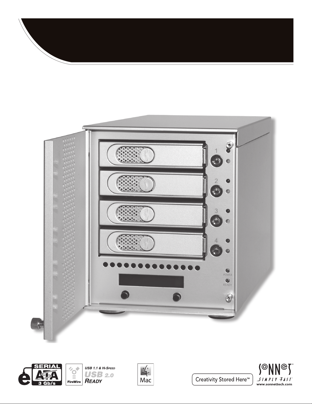
4-Bay Serial ATA Disk Enclosure with Quad Interface
D
400
QR
5
User’s Guide
Windows
Page 2
Fusion D400QR5 Specifications and Features
Enclosure Specifications
Drive Tray (Bay 1)
Drive Tray (Bay 2)
Drive Tray (Bay 3)
Drive Tray (Bay 4)
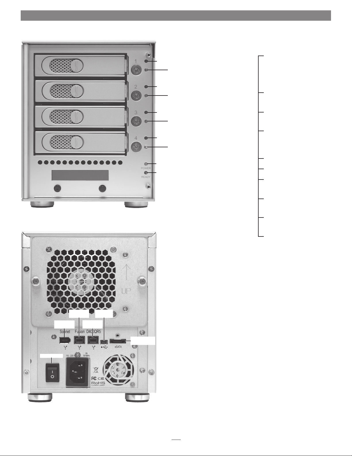
Display and Controls
Figure 1
Drive Presence LED
(Bay 1)
Drive Activit y/Fault
LED (Bay 1)
Drive Presence LED
(Bay 2)
Drive Activit y/Fault
LED (Bay 2)
Drive Presence LED
(Bay 3)
Drive Activit y/Fault
LED (Bay 3)
Drive Presence LED
(Bay 4)
Drive Activit y/Fault
LED (Bay 4)
Enclosure Power LED
Ready Indicator LED
Compatibility Compatible with Mac®,
Windows®, and Linux®
computers with compatible
interface
Interface Connectors eSATA, 2 x FireWire 800,
FireWire 400, Mini-USB
Drives Supported 3 & 1.5 Gb/s Serial ATA;
7,200 RPM
Data Transfer Speed Up to 225MB per second,
depending on interface
used and configuration
OS Support Platform independent
Power Supply 100–240V, 50–60Hz
Operating Temperature 32 to 95˚ F
(0˚ C to +35˚ C)
Dimensions (WxDxH) 5.9 x 11.25 x 7.5 in
(14,9 x 28,5 x 19 cm)
Weight 9.1 lbs
(4.1 kg)
FireWire 400
Connector
Power Switch
FireWire 800
Connector
FireWire 800
Connector
Connector
Mini-USB
Locking eSATA
Connector
Package Contents Disk enclosure, four 3.5"
drive trays, drive tray keys,
drive mounting screws, tube
of threadlocker, power cord,
2-meter locking eSATA data
cable, 2-meter FireWire 800
cable, 2-meter FireWire 400
cable, 2-meter USB cable,
User’s Guide
Figure 2
2
Page 3

Safety Precautions and Disclaimers
SAFETY PRECAUTIONS
Please read this section carefully before proceeding. These
precautions explain the correct and safe use of this device,
thereby helping to prevent injury to you or others, and also help
you to minimize the risk of damaging the device.
Warnings
Always follow the basic warnings listed here to avoid the risk of
serious injury or death from electrical shock, short-circuiting, fire,
and other hazards. These warnings include, but are not limited to:
• With the exception of the user-swappable parts, do not attempt
to disassemble or modify the enclosure. If this device appears to
be malfunctioning, contact your reseller or local distributor.
• Do not drop the enclosure or any of its drive modules;
dropping or mishandling of the enclosure or drive modules
may result in a malfunction.
• Do not insert your fingers or foreign objects inside the enclosure;
take particular care when small children are present.
• Do not expose the device to rain, use it near water or containers
that contain liquids which might spill into any openings, or in
damp or wet conditions.
• If unusual smells, sounds, or smoke come from the device, or if
liquids enter it, switch it off immediately and unplug it from the
electrical outlet.
• Follow the instructions in this manual carefully; contact your
reseller or local distributor for additional advice not covered in
this User’s Guide.
DISCLAIMERS
Drive Usage:
Sonnet Technologies has qualified the hard drives listed below
for use in Fusion D400QR5 storage systems. These drives were
chosen for their superior performance, error handling, and
reliability characteristics, especially when used in RAID groups.
One important difference between these drives and standard
hard drives is how quickly each handles read errors—these
qualified drives attempt to recover from errors for just a few
seconds, while standard hard drives may take minutes. Because
RAID controller cards and software-based RAID schemes allow
only a very short time for drives to recover before dropping them
from the RAID group, hard drive manufacturers recommend
against using standard hard drives in RAID storage systems. The
hard drives qualified by Sonnet also feature improved vibration
characteristics that influence and support storage reliability. We
recommend the use of these Enterprise/RAID edition hard drives
and select, Sonnet certified desktop hard drives in your Fusion
storage system to ensure system reliability and performance.
STANDARD DRIVES MAY NOT BE SUPPORTED AND MAY
DEGRADE SYSTEM RELIABILITY AND PERFORMANCE. Check
the Sonnet Web site for the latest list of qualified hard drives.
500GB Models
• Hitachi Deskstar E7K500, # HDS725050KLA360
• Hitachi Ultrastar A7K1000, # HUA721050KLA330
• Maxtor MaXLine Pro 500, # 7H500F0
• Samsung Spinpoint F RAID, # HE502IJ
• Seagate Barracuda ES, # ST3500630NS
• Seagate Barracuda ES.2, # ST3500320NS
• Western Digital RE3 Enterprise, # WD5002ABYS
750GB Models
• Hitachi Ultrastar A7K1000, # HUA721075KLA330
• Samsung Spinpoint F RAID, # HE753LJ
• Seagate Barracuda ES, # ST3750640NS
• Seagate Barracuda ES.2, # ST3750330NS
• Western Digital, RE3 Enterprise, # WD7502ABYS
(1)
(1)
1TB Models
• Hitachi Ultrastar A7K1000, # HUA721010KLA330
• Samsung Spinpoint F RAID, # HE103UJ
• Seagate Barracuda ES.2, # ST31000340NS
(1)
• Western Digital, RE3 Enterprise, # WD1002FBYS
1.5TB Models
• Seagate Barracuda 7200.11, # ST31500341AS
(2)
2TB Models
• Western Digital RE4-GP, # WD2002FYPS
(1) Only Seagate ES.2 drives with firmware versions SN06 and
newer compatible. Seagate ES.2 drives with firmware versions
SN03, SN04, or SN05 are NOT compatible.
(2) Only Seagate Barracuda 7200.11 1.5TB drives with firmware
versions SD1B and newer compatible.
3
Page 4
Drive Installation and Enclosure Setup
1. Remove the Fusion D400QR5 and its drive trays from their
packaging, and place them near the computer to which the
enclosure will be connected.
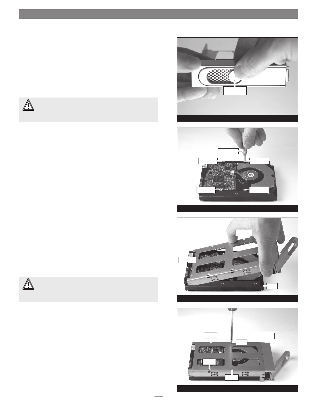
2. Take one of the drive trays and push its lever release button in
until the lever pops out (Figure 3).
WARNING: When handling computer products, take care to
prevent components from being damaged by static electricity;
avoid working in carpeted areas. Handle hard drives only by their
edges and avoid touching connector traces and component pins.
3. Remove a SATA drive from its packaging and set it in on a flat,
level surface with the label side down. Open the supplied tube
of threadlocker and apply a single drop inside each of the four
indicated screw holes on the bottom of the drive (Figure 4).
screw hole
push in lever
release button
Figure 3
threadlocker
screw hole
4. Turn the drive tray upside down and lay it on top of the drive,
with the back of the tray facing toward the drive’s connectors
(Figure 5).
WARNING: When securing the trays to the hard drives, you
must verify the screw heads are flush with the tray. Otherwise,
a screw may catch on the tray below and prevent you from removing
the tray from the enclosure.
5. Using four of the supplied screws, secure the drive tray to the
drive; tighten each screw to secure the tray snugly to the drive;
do not overtighten the screws (Figure 6).
connectors
screw hole
screw
screw hole
Figure 4
drive tray
drive
Figure 5
drive tray
screw
screw
screw
Figure 6
4
Page 5

Drive Installation and Enclosure Setup
WARNING: When inserting drive modules into the enclosure,
do not force the levers closed. If a lever does not close easily,
remove and reinsert the module, and then push the lever in again.
6. Carefully slide the drive module into the enclosure until its lever
starts to close, and then push the lever in until it clicks to secure
the drive module inside the enclosure (Figure 7); verify that the
drive modules are all plugged in securely.
push lever
until it clicks
7. Repeat steps 2-6 for additional drives.
Connect Fusion D400QR5 to Computer and Power Outlet
1. Using one of the supplied cables (eSATA, FireWire 800, FireWire
400, USB), connect the Fusion D400QR5 to your computer. For
maximum performance, connect the D400QR5 to a SATA host
controller card.
Support Note: The supplied Sonnet locking eSATA cable is
compatible with all eSATA ports and provides a far more
secure connection when used with Sonnet drive enclosures and host
controller cards with the matching connector. If necessary, you may
remove the locking mechanism from the connector by removing the
screws securing the two halves.
2. Connect the supplied power cable between the Fusion D400QR5
and a grounded wall outlet or power strip; verify the cable is
plugged in securely.
push tray in
until the lever
starts to close
Figure 7
5
Page 6
Drive Installation and Enclosure Setup
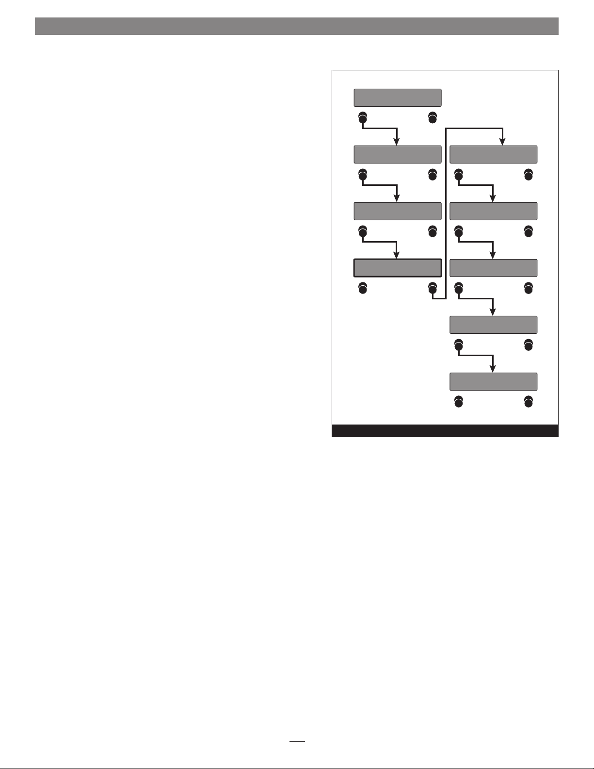
Initial Drive Configuration
When you first turn on the Fusion D400QR5 after installing the hard
drives, you must configure the drives as a RAID 0 or RAID 5 set before
formatting the virtual volume using your operating system drive
formatting application.
De tecti
–Re—In
ng Disk
it?
s
WARNING: Configuring the drives in your Fusion D400QR5
enclosure following the steps below requires you to reformat
them. Reformatting the drives will erase any data on them! If
there is any data on them, back it up first outside of the Fusion system
before configuring the drives.
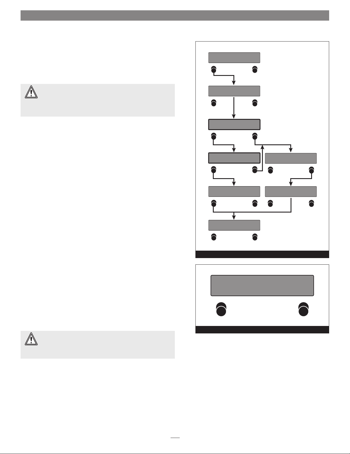
1. Power up the Fusion D400QR5 and press the button under
Re-Init? on the display (Figure 8). If you do not press the button
within 10 seconds of powering up the enclosure, a Halted, Invalid
RAID message appears (Figure 9); shut off the power and then
turn it back on again.
2. Detecting Disks, waiting appears briefly on the display, followed
by RAID0 4D. If you want to format your drives as a RAID 0 set,
press the button under Format on the display, and then skip to
step 4. Otherwise, press the button under Next (Figure 8).
3. RAID5 4D is displayed; if you want to format your drives as a
RAID 5 set, press the button under Format on the display. If you
made a mistake, press the button under Next and then under
Quit; shut off the power, turn it back on again, and then return to
step 1 (Figure 8).
4. After you select the RAID mode configuration, Are you sure?
appears; press the button under Format (Figure 8).
Detec ti
waiti
RAID0
–Next
RAID5
–Next
–Quit
Fusion QR5 v1.0
–Menu
ng Disk
n
4D
Fo
4D
Fo
g
r
r
mat
mat
s
–
–
Figure 8
A
re you sure?
–Quit
A
re you sure?
waiti
Format
–
g
n
5. Are you sure?, waiting appears briefly while the drives are
configured, and then the main menu appears (Figure 8). You
may now format the drives using your computer’s operating
system drive formatting application; go to page 7.
Change Drive Configuration
You may change the drive configuration from RAID 0 to RAID 5, or
vice-versa, following the steps listed in Initial Drive Configuration
above.
WARNING: Reconfiguring the drives in your Fusion D400QR5
enclosure requires you to reformat them. Reformatting the
drives will erase any data on them! If there is any data on them,
back it up before configuring the drives.
––HA
I
nva
lid RAID
LTED
Figure 9
––
6
Page 7

Operating System Drive Formatting Instructions
Mac OS Users’ Instructions
1. Assuming your computer is on, after the Fusion D400QR5
configures the drives a Disk Insertion window will appear
stating that there is an unreadable volume; click Initialize,
and then Disk Utility will open.
2. In the Disk Utility window, the RAID group will appear as a
single volume. Select the volume, and then click the Erase tab
at the top of the window.
3. Click Erase; a window will appear asking you to approve
your choice.
4. Click Erase; the Fusion D400QR5 volume will appear on
your computer’s desktop.
5. Close Disk Utility; the drive is ready for use.
Windows 7/Vista/Server 2008 Users’ Instructions
1. Select Computer Management From the Windows Start
menu. If Computer Management is not available in the Start
Menu, select Start > Control Panel > Administrative Tools.
In the Administrative Tools window, double-click Computer
Management.
10. Depending on how you configured the RAID group, it may
already be available to the system. Once the RAID group has
been formatted and finishes building, it is ready to use.
Windows XP/Server 2003 Users’ Instructions
Support Note for Windows XP Users: Windows XP
32-bit does not support volumes greater than 2TB.
Windows XP x64, Vista Ultimate/Enterprise, 7 (Professional,
Enterprise or Ultimate), and Windows Server 2008 and 2003 support
volumes greater than 2TB, but must be formatted using the GPT file
system, which is not accessible by Windows XP 32-bit systems.
1. Select Computer Management From the Windows Start menu.
If it is not available in the Start Menu, select Start > Settings >
Control Panel > Administrative Tools. In the Administrative
Tools window, double-click Computer Management.
2. In the Computer Management window, click Storage on the
left, and then double-click Disk Management.
3. When the Initialize and Convert window appears, click OK.
4. When the Select Disks to Initialize window appears, select the
RAID volume(s), and then click Next.
2. In the Computer Management window, click Storage on the
left, and then double-click Disk Management.
3. When the Initialize Disk window appears, select the RAID
volume you created. Select the MBR partition style if you
need to access your RAID storage from a computer running
Windows XP Professional or 32-bit Windows Server 2003;
otherwise, select GPT. Click OK.
4. In the Disk Management window, the Fusion D400QR5 RAID
group will appear (listed as “unallocated”) as a single volume.
Right-click where the word “unallocated” appears, and then
select New Simple Volume.
5. When the Welcome to the New Simple Volume Wizard window
appears, click next to start the process.
6. Follow the remaining steps to complete the process.
Note: If you do not select the quick format option, this process will take
much longer to complete.
7. When the Assign Drive Letter or Path window appears, select
Assign the following drive letter, choose a letter, and then
click Next.
8. When the Format Partition window appears, enter a new
name for the volume table if you’d like. Select Perform a quick
format, and then click Next.
9. When the next window appears, click Finish.
5. When the next window appears, click Finish.
6. In the Disk Management window, the Fusion D400QR5 RAID
group will appear (listed as “unallocated”) as a single volume.
Right-click where the word “unallocated” appears, and then
select New Partition.
7. When the Welcome to the New Partition Wizard window
appears, click Next.
8. When the Select Partition Type window appears, select Primary
Partition, and then click Next.
9. When the Specify Partition Size window appears, click next.
10. When the Assign Drive Letter or Path window appears, select
Assign the following drive letter, choose a letter, and then
click Next.
11. When the Format Partition window appears, enter a new
name for the volume table if you’d like. Select Perform a quick
format, and then click Next.
12. When the next window appears, click Finish.
Note: If you do not select the quick format option, this process will take
much longer to complete.
13. Depending on how you configured the RAID group, it may
already be available to the system. Once the RAID group has
been formatted and finishes building, it is ready to use.
7
Page 8

Menus
View the RAID Mode
1. Press the button under Menu on the display; RAID Mode appears
(Figure 10).
2. Press the button under Go on the display; the RAID mode
appears (Figure 10).
3. Press the button under Quit on the display to return to the main
menu (Figure 10).
Fusion QR5 v1.0
–Menu
RAID Mode
–Next Go–
View the Error Statistics
The Fusion D400QR5 enclosure displays statistics
for minor (recoverable) and major (persistent)
read/write errors for each of the drives.
1. Press the button under Menu twice; Error
Statistics appears (Figure 11).
2. Press the button under Go on the display;
Persistent appears (Figure 11).
3. Press the button under Go on the display to
view persistent error statistics; skip to step 5.
Otherwise, Press the button under Next on
the display; Recoverable appears (Figure 11).
Fusion QR5 v1.0
–Menu
RAID Mode
–Next Go–
Error Statistics
–Next Go–
RAID5
–Quit
Fusion QR5 v1.0
–Menu
Drive :1 – 0
–Next
Drive :2 – 0
–Next
4D
Figure 10
Drive :1 – 0
–Next
Drive :2 – 0
–Next
4. Press the button under Go on the display to
view recoverable error statistics (Figure 11).
5. Drive:1 – x (x = the number) appears. Note the
number of errors, press the button under Next
on the display for drives 2, 3, and 4, and then
press the button under Quit to return to the
main menu (Figure 11).
Support Note: Minor errors are
generally not a cause for concern, but
may be used to monitor a drive’s health. Major
errors generally cause the RAID group to become
degraded and possibly require the drive to
be replaced. When there is a major problem
with a drive, a red fault indicator lights up,
accompanied by a message on the display.
Persistent
–Next Go–
Recoverable
Go––Quit
8
Drive :3 – 0
–Next
Drive :4 – 0
–Quit
Fusion QR5 v1.0
–Menu
Figure 11
Drive :3 – 0
–Next
Drive :4 – 0
–Quit
Page 9
Menus
View Drive S.M.A.R.T. Status
Self-Monitoring, Analysis and Reporting Technology, or S.M.A.R.T.,
is a monitoring system for SATA drives to detect and report on
various indicators of drive health. The S.M.A.R.T. feature keeps
track and reports the status of SATA drive health using certain
parameters recorded by the drives. The Fusion D400QR5 displays
two possibilities: good, or failing. Drives marked as Failing should be
replaced.
1. Press the button under Menu three times; SMART Status appears
(Figure 12).
2. Press the button under Go on the display; drive 1 S.M.A.R.T.
status is displayed (Figure 12).
3. Press the button under Next on the display for drives 2, 3, and
4, and then press the button under Quit to return to the main
menu (Figure 12).
Fusion QR5 v1.0
–Menu
RAID Mode
–Next Go–
Error Statistics
–Next Go–
SMART Status
–Next Go–
Drive :1 – Good
–Next
Drive :2 – Good
–Next
Drive :3 – Good
–Next
Drive :4 – Good
–Quit
Fusion QR5 v1.0
–Menu
Figure 12
9
Page 10

Menus
View Drive Temperatures
SATA hard drives monitor their own temperature and report it to the
Fusion D400QR5.
1. Press the button under Menu four times; Disk Temp appears
(Figure 13).
2. Press the button under Go on the display; Drive:1 temperature is
displayed in degrees Celsius (Figure 13).
3. Press the button under Next on the display for drives 2, 3, and
4, and then press the button under Quit to return to the main
menu (Figure 13).
Support Note: It is perfectly normal for the temperatures of
the drives to vary from one to another within a few degrees.
Fusion QR5 v1.0
–Menu
RAID Mode
–Next Go–
Error Statistics
–Next Go–
SMART Status
–Next Go–
Drive :1:
–Next
Drive :2:
–Next
Drive :3:
–Next
37
36
36
Disk Tem
p
Go––Quit
Drive :4:
–Quit
Fusion QR5 v1.0
–Menu
Figure 13
35
10
Page 11

Tips and Additional Information
This section covers some tips for using the Fusion D400QR5
enclosure.
Hot-swapping:
When connected via eSATA data cable to a Mac running Mac
OS X, Fusion D400QR5 supports hot-swapping*, enabling you
to exchange a set of drives without having to shut down your
computer. This does not mean you can simply pull out the drives
at any time; you must follow the procedures below or you may
lose data, or cause the system to go into a degraded state in the
process.
• Before removing any of the drive modules, you must put away
(“eject”, “unmount”, “dismount”) the drive volume. Simply
drag the drive icon associated with the drive(s) you wish to
remove to the eject icon on the dock (or trash can on the
desktop).
• Power off the enclosure before reinserting the drive
modules. Once the modules are secured, power on the
enclosure again; this will ensure that the RAID set will mount
properly.
* Windows does not provide hot swap support for drives (drive
enclosures) connected to a SATA host controller card installed in a
desktop PC or server.
Connections:
• Fusion D400QR5 supports only one interface at a time.
Do not connect more than one cable at a time between the
enclosure and computer; no damage will occur, but only one
interface will function.
Contacting Sonnet Customer Service
USA Customers
The Sonnet Web site located at www.sonnettech.com has the
most current support information and technical updates. Before
you call Sonnet Customer Service, please check our Web site for
the latest updates and online support files, and check this User’s
Guide for helpful information. When you call Sonnet Customer
Service, have the following information available so our customer
service staff can better assist you:
• Product name
• Date and place of purchase
• Hard drive model(s)
• Computer model
• Operating system
• Software/firmware versions
If further assistance is needed, please contact us at:
Sonnet Customer Service:
Online Service Form: http://serviceform.sonnettech.com
Tel: 1-949-472-2772
(Monday–Friday, 7 a.m.–4 p.m. Pacific Time)
Fax: 1-949-457-6349
E-mail: support@sonnettech.com
For Customers Outside the USA
For support on this product outside the USA, contact your reseller
or local distributor.
Visit Our Web Site
For the most current product information and online support
files, visit the Sonnet Web site at www.sonnettech.com/support/.
Remember to register your product online at http://registration.
sonnettech.com to be informed of future upgrades and product
releases.
11
Page 12

©2010 Sonnet Technologies, Inc. All rights reserved. Sonnet, the Sonnet logotype , Simply Fast, the Simply Fast logotype, Creativity Stored Here, and Fusion are trademarks of Sonnet Technologies, Inc. FireWire, Macintosh,
Mac, the Mac logo, and Mac OS are trademarks of Apple Inc., registered in the United States and other countries. Other product names are trademarks of their respective owners. Product specifications subject to change
without notice. Printed in the USA. UG-FUS-D4QR5-0TB-E-B-041210
 Loading...