

Page 1
Sonnet AV/HPV Card Video Adapter Kit
Installation Instructions for Power Macintosh 7100 and 8100
Adapter Kit Inventory
Before installing the AV/HPV Card Video Adapter, you will require the
following items (Figure 1):
Included with adapter kit: Needed; not included with adapter kit:
1) Video adapter board 6) Small flatblade screwdriver
2) Video flex cable 7) Small Philips screwdriver
3) Two 4-40 nuts 8) Crescendo NuBus processor upgrade card
4) Support standoff 9) PDS-based AV card or HPV card
(required for 7100 only) (AV card shown in illustration)
5) Two assembly standoffs
(required for 8100 only)
We suggest that you inventory and lay the items out in front of you prior
to proceeding with the installation of the AV/HPV Card Video Adapter Kit.
For the installation of the AV/HPV Card Video Adapter kit in a Power
Macintosh
™
7100, continue with instructions below; for the Power
Macintosh 8100, skip to page 7.
AV/HPV Card Video Adapter Kit – Power Macintosh
7100 Installation
1. Shut down your Power Macintosh. If the computer has been on for
any length of time, wait a few minutes for it to cool before beginning
the installation.
2. Disconnect the power and peripheral cables from the back of the
computer and move it to an area where you can freely work.
3. Open your Power Macintosh by first loosening the security screw
(Figure 2) on the back of the case with a large flatblade screwdriver;
then, gently slide the case cover off the computer.
4.Turn over the cover and locate the large cutout in the support framing
(Figure 3). This cutout provides the necessary clearance required for the
adapter kit to fit inside the computer. Take care when removing and
replacing the cover onto your computer to prevent damaging the
adapter’s video flex cable as it fits into this cutout.
5. Set the cover aside.
6. Identify the internal components of your computer (Figure 4). Touch
the power supply metal shielding to discharge any potential damaging
static electricity.
Figure 2: Loosen security screw and remove case cover
Figure 1: Items needed for Crescendo card
installation with AV or HPV card
security screw
PDS slot port
(with AV card)
1
9
6
Needed; not included
Included with
adapter kit
NuBus slot ports
Figure 4: Touch metal shielding to discharge static
3
2
4
5
8
7
Support Note:
IMPORTANT! –
The video adapter board installs into
the middle NuBus slot since it aligns with the proper clearance in the
support framing of the computer's case. The video adapter board uses the
middle NuBus slot as a holder; it does not convert your AV or HPV card into a
NuBus card.
We recommend that you make a backup of important information on your hard
drive prior to installing new hardware or software. When handling computer
products, you must take care to prevent components from being damaged by
static electricity. Avoid carpeted areas, handle processor upgrade cards only by
their edges, and avoid touching connector traces and component pins.
NuBus slots
PDS slot (with AV or HPV card)
power supply
metal shielding
Figure 3: Location of large cutout in cover
(back of
case)
cutout in cover
(front of
case)
Software updates and links are available from the Sonnet web site at www.sonnettech.com.
Sonnet Technologies Customer Service hours are Monday-Friday, 8am-5pm PT.
Customer Service Phone: 1-949-472-2772 • E-mail: support@sonnettech.com
Sonnet Technologies, Inc., 15 Whatney, Irvine, California 92618-2808 USA • Tel: 1-949-587-3500 • Fax:1-949-457-6350
©1999 Sonnet Technologies, Inc. Revised 2000. All rights reserved. Sonnet, the Sonnet logotype,Simply Fast, the Simply Fast logotype, and Crescendo are trademarks of Sonnet Technologies, Inc. Macintosh,Mac, and
the Mac logo are trademarks of Apple Computer, Inc., registered in the U.S.and other countries.The PowerPC name and the PowerPC logotype are trademarks of International Business Machines Corporation, used
under license therefrom. Other product names are trademarks of their respective owners.Product specifications are subject to change without notice. Printed in the U.S.A.C61A-7181-090500
Page 2
Sonnet AV/HPV Card Video Adapter Kit
2
7. Locate the PDS slot (Figure 5). If there is a PDS card installed (such as
the Apple AV or HPV card or Sonnet Crescendo card), remove it and set
it aside.
8. Locate the NuBus slots (Figure 5). If any NuBus cards are installed,
temporarily remove them so you have better clearance for installing the
video adapter board. If you have three NuBus cards in your computer,
you will only be able to reinstall two of them. The middle NuBus slot is
required for the adapter board.
9. Determine if you have an AV or HPV card as follows:
• AV Card – The AV card has a single 15-pin monitor connector for a
monitor and S-Video In and S-Video Out ports (Figure 6) that support
Audio/Video features.
• HPV Card – The HPV (High Performance Video) card has a single
15-pin monitor connector for a monitor and four onboard Video RAM
(VRAM) slots (Figure 7).
10. Before attaching the AV or HPV card to the video adapter board, you
need to bend the metal tab 90° at the end of the AV card (Figure 8) or
HPV card (Figure 9) with a small flatblade screwdriver so it fits in its
new location.
(Installation instructions continued…)
Figure 5: Location of PDS slot and NuBus slots
Figure 6: AV card
Figure 7: HPV card
Figure 8: Bend back metal tab on AV Card
bend tab from original position here
90°
angle
Figure 9: Bend back metal tab on HPV card
bend tab from original position here
90°
angle
S-Video In port
S-Video Out port
15-pin monitor connector
NuBus slots
PDS slot (with AV or HPV card)
to here
to here
Four VRAM slots
15-pin monitor connector
Page 3
11. Affix AV or HPV Card to Video Adapter Board
HPV Card Installation
• Orient the video adapter board in front of you as shown in Figure 10.
Using a small Phillips screwdriver, remove the upper left stand-off from
the adapter board (Figure 10).
• Align the HPV card directly over the video adapter board with the
connector of the HPV card facing upward (Figure 11). The holes
on the HPV card should align directly with the upper right and lower
left standoffs on the adapter board.
• Secure the HPV card to the video adapter board with the two nuts
(Figure 12) supplied with the adapter kit.
• Continue with the instructions at step 12.
AV Card Installation
• Orient the video adapter board in front of you as shown in Figure 13.
Align the AV card directly over the adapter board with the connector of
the AV card facing upward (Figure 13). The holes on the AV card
should align directly with the standoffs on the adapter board.
• Secure the AV card to the video adapter board with the two nuts
(Figure 14) supplied with the adapter kit.
• Continue with the instructions at step 12.
(Installation instructions continued…)
Sonnet AV/HPV Card Video Adapter Kit
3
standoff
HPV card connector facing upwards
Figure 10: Remove upper left standoff
Figure 12: Secure HPV card to adapter board with nuts
Figure 11: Orient HPV card over adapter board
AV card connector facing upward
Figure 13: Orient AV card over adapter board
Figure 14: Secure AV card to adapter board with nuts
Page 4

Figure 15: Screw support stand-off onto Crescendo card
Sonnet AV/HPV Card Video Adapter Kit
4
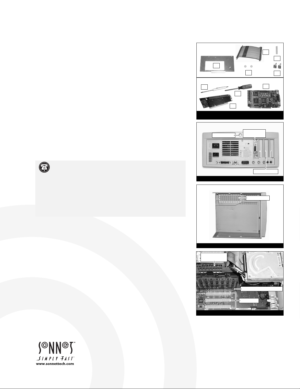
12. Place the Crescendo card in front of you with the pass-through slot facing
upward. Screw the support stand-off (supplied with the adapter kit) onto
the card (Figure 15).
13. Install the video flex cable into the pass-through slot of the Crescendo
card (note the notch in the cable for orientation). Press down on the
outer edges of the cable until it is firmly seated (Figure 16).
14. Align the Crescendo card over the PDS slot on the logic board with the
card’s heatsink facing toward the power supply. Gently press down until
the card is firmly seated in the PDS slot (Figure 17).
15. Remove the access port cover (if installed) from the middle NuBus port
located at the back of the computer (Figure 18). Use your finger or a
small flatblade screwdriver to push it out from the port as shown in
Figure 18.
16. Insert the access port cover into the PDS port (Figure 19).
(Installation instructions continued…)
Figure 17: Install Crescendo card into PDS slot
Figure 18: Push out middle NuBus port cover
Figure 19: Insert access port cover into PDS port
Figure 16: Attach video flex cable to Crescendo card
notch in cable
pass-through slot
pass-through slot
PDS slot
Crescendo card
(with attached video flex cable)
Page 5

Sonnet AV/HPV Card Video Adapter Kit
5
17. If you are reinstalling any NuBus cards, first install a NuBus card into the
NuBus slot closest to the power supply. Then, align the video adapter
board over the middle NuBus slot on the logic board with the inverted
AV or HPV card on the adapter board facing toward the power supply
(Figure 20). Verify the adapter board lines up with the inline NuBus
guides of the 7100’s case. Gently press down on the adapter board (not
directly on the AV or HPV card) until the adapter board is firmly seated
in the middle NuBus slot. If you encounter excessive resistance, check
for bent connector pins, re-align the adapter board over the middle
NuBus slot, and gently press down again. If you have a second NuBus
card to install, install it into the outer NuBus slot.
18. Attach the connector on the video flex cable to the AV or HPV card
(Figure 21). Gently press down on the outer edges of the connector to
avoid pricking your fingers on the series of pins on top of the connector.
If necessary, use a piece of foam from the packaging material your card
shipped in to provide a cushion between your finger and the pins.
19. Return the computer to your computing area.
20. IMPORTANT! – Before replacing the cover onto your computer, attach
your monitor’s video cable to the AV or HPV card 15-pin monitor
connector (Figure 22). Secure the cable by tightening the thumbscrews
on the cable’s connector. Connecting the cable anchors the card in place
while replacing the cover.
21. Turn over the cover and locate the large cutout in the support framing
(Figure 23). This cutout provides the necessary clearance required for
the video adapter board to fit inside the computer. Take care when
removing and replacing the cover onto your computer to prevent
damaging the adapter’s video flex cable.
22. Carefully replace the cover onto your computer by slanting the front
end of the cover over the computer (Figure 24). Confirm the inner
grooves of the bottom of the case align with the tabs in the cover. As
you slide back the cover, the top of the video adapter board and
attached flex cable should fit nicely into the cutout of the cover. When
the cutout of the cover clears the connector, you can lower
the cover into place.
(Installation instructions continued…)
Figure 20: Install adapter board into middle NuBus slot
Figure 21: Attach video flex cable to AV or HPV card
Figure 22: Reattach 15-pin monitor connector
Figure 23: Location of large cutout in cover
middle NuBus slot
attach connector
video adapter board
(with attached AV or HPV card)
(back of
case)
cutout in cover
(front of
case)
Figure 24: Replace case cover onto computer
line tabs in cover with inner grooves of case
15-pin monitor connector
Page 6

Sonnet AV/HPV Card Video Adapter Kit
6
Figure 25: Verify cover aligns with support runner
Figure 26: Finish sliding case cover onto computer
23. Make certain the cover lines up with the support runner of the
computer’s case (Figure 25). The video adapter board should be firmly
in place and not misaligned with the access port slot. If the video
adapter board appears “tweaked” you will need to carefully realign the
case back onto the computer.
24. Finish sliding the cover onto the computer until it lines up with
the rear of the computer (Figure 26).
25. Once the cover is in place, tighten the security screw on the back of
computer’s case.
26. Reconnect the power and peripheral cables to the computer.
27. Turn on your Power Macintosh. Your newly accelerated machine should
boot as normal.
cover should align with support runner
adapter board should be firmly in place
Page 7

Sonnet AV/HPV Card Video Adapter Kit
7
Figure 27: Loosen security screws and remove case cover
Figure 28: Touch metal shielding to discharge static
Figure 29: Remove any cards from PDS and NuBus slots
AV/HPV Card Video Adapter Kit – Power Macintosh
8100 Installation
1. Shut down your Power Macintosh. If the computer has been on for
any length of time, wait a few minutes for it to cool before beginning
the installation.
2. Disconnect the power and peripheral cables from the back of the
computer and move it to an area where you can freely work.
3. Open your Power Macintosh by first loosening the four security screws
on the back of the case with a large flatblade screwdriver; then, gently
slide the case cover off the computer (Figure 27).
4. Lay the computer on a flat surface so that you may gain access to the
interior of the computer (Figure 28).
5. Identify the internal components of your computer. Touch the power
supply metal shielding (Figure 28) to discharge any potential damaging
static electricity.
6. Locate the PDS slot (Figure 29) directly under the metal shielding of
the internal power supply. If there is a PDS card installed (such as the
Apple AV or HPV card or Sonnet Crescendo card), remove it. Gently
unlatch the inner case tab away from the PDS card with your finger or
the head of a small flatblade screwdriver (Figure 29, inset), then grasp
the edges of the card firmly and pull it out of the PDS slot.
7. Locate the NuBus slots (Figure 29). If any NuBus cards are installed,
temporarily remove them so you have better clearance for installing the
video adapter board. If you have three NuBus cards in your computer,
you will only be able to reinstall two of them. The middle NuBus slot is
required for the adapter board.
8. Determine if you have an AV or HPV card as follows:
• AV Card – The AV card has a single 15-pin monitor connector for a
monitor and S-Video In and S-Video Out ports (Figure 30) that support
Audio/Video features.
• HPV Card – The HPV (High Performance Video) card has a single
15-pin monitor connector for a monitor and four onboard Video RAM
(VRAM) slots (Figure 30).
(Installation instructions continued…)
Support Note:
IMPORTANT! –
The video adapter board installs into
the middle NuBus slot of your computer. The video adapter board uses
the middle NuBus slot as a holder; it does not convert your AV or HPV card into
a NuBus card.
We recommend that you make a backup of important information on your hard
drive prior to installing new hardware or software. When handling computer
products, you must take care to prevent components from being damaged by
static electricity. Avoid carpeted areas, handle processor upgrade cards only by
their edges, and avoid touching connector traces and component pins.
power supply
metal shielding
PDS slot (with AV
or HPV card)
NuBus slots
Figure 30: AV card
Figure 31: HPV card
S-Video In port
S-Video Out port
15-pin monitor connector
Four VRAM slots
15-pin monitor connector
PDS slot (with AV
or HPV card)
NuBus slots
tab
Page 8

Sonnet AV/HPV Card Video Adapter Kit
8
Figure 34: Assemble subassembly standoffs for HPV card
Figure 35: Secure HPV card to adapter board with nuts
Figure 36: Assemble subassembly standoffs for AV card
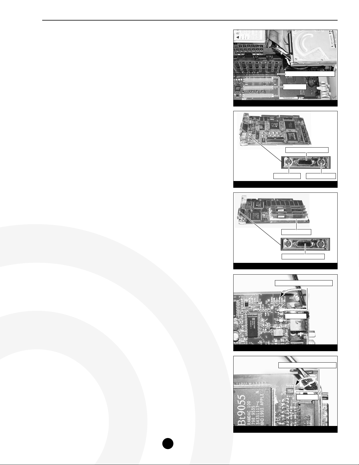
9. Before attaching the AV or HPV card to the video adapter board, you
need to bend the metal tab 90° at the end of the AV card (Figure 32) or
HPV card (Figure 33) with a small flatblade screwdriver so it fits in its
new location.
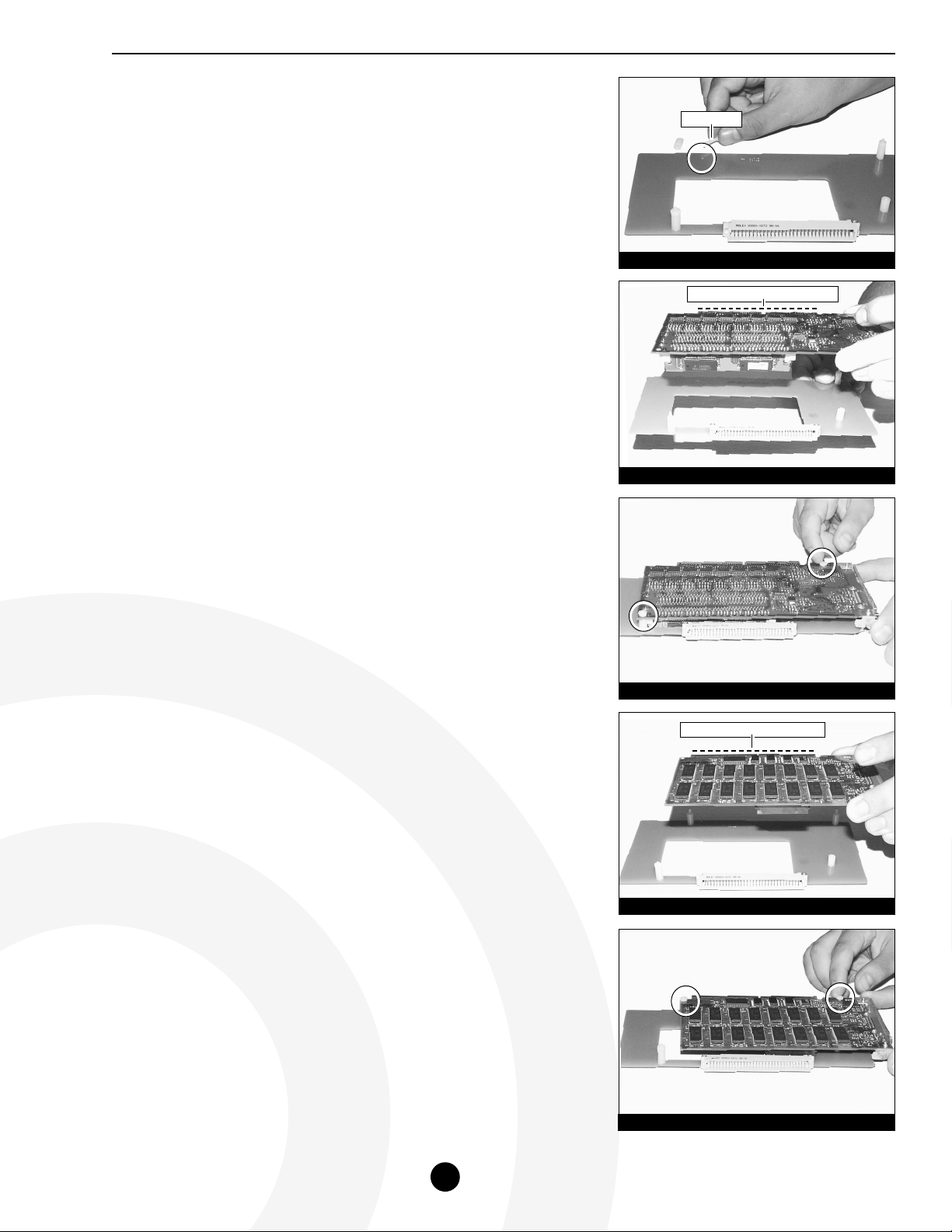
10. Affix AV or HPV Card to Video Adapter Board
HPV Card Installation
• Using a small Phillips screwdriver, remove the three standoffs from
the video adapter board. Locate the two subassembly standoffs from
the video adapter packaging. Assemble and secure one subassembly
standoff to the upper right corner of the board, and the other
subassembly standoff to the lower left corner (Figure 34).
• Align the HPV card directly over the video adapter board with the
connector of the HPV card facing upwards (Figure 35). The holes
on the HPV card should align directly with the standoffs on the
adapter board. Secure the HPV card to the video adapter board with the
two nuts (Figure 35) supplied with the adapter kit.
• Continue with the instructions at step 11.
AV Card Installation
• Using a small Phillips screwdriver, remove the three standoffs from
the video adapter board. Locate the two subassembly standoffs
from the video adapter packaging. Assemble and secure the two
subassembly standoffs to the upper left and right corners of the
adapter board (Figure 36).
• Align the AV card directly over the video adapter board with the
connector of the AV card facing upward (Figure 37). The holes
on the AV card should align directly with the standoffs on the adapter
board. Secure the AV card to the video adapter board with the two nuts
(Figure 37) supplied with the adapter kit.
• Continue with the instructions at step 11.
(Installation instructions continued…)
Figure 32: Bend back metal tab on AV card
bend tab from original position here
90°
angle
Figure 33: Bend back metal tab on HPV card
bend tab from original position here
90°
angle
to here
to here
subassembly
standoff
subassembly
standoff
HPV card connector facing upwards
subassembly
standoff
subassembly
standoff
Page 9

Sonnet AV/HPV Card Video Adapter Kit
9
Figure 37: Secure AV card to adapter board with nuts
Figure 39: Install Crescendo card into PDS slot
Figure 40: Push out middle NuBus access port cover
Figure 41: Insert access port cover into PDS slot
11. Attach the video flex cable into the pass-through slot of the Crescendo
card (note the notch in the cable for orientation). Press down on the
outer edges of the cable until it is firmly seated (Figure 38).
12. Align the Crescendo card over the PDS slot on the logic board with the
card’s heatsink facing toward the power supply. Gently press down until
the card is firmly seated in the PDS slot (Figure 39).
13. Remove the access port cover (if installed) from the middle NuBus port
located at the back of the computer (Figure 40). Use your finger or a
small flatblade screwdriver to push it out from the port as shown in
Figure 40.
14. Insert the access port cover into the PDS port (Figure 41).
(Installation instructions continued…)
AV card connector facing upward
Figure 38: Attach video flex cable to Crescendo card
notch in cable
pass-through slot
PDS slot
Crescendo card
(with attached video flex cable)
Page 10

Sonnet AV/HPV Card Video Adapter Kit
10
Figure 42: Install adapter board into middle NuBus slot
Figure 43: Attach video flex cable to AV or HPV card
Figure 44: Reattach 15-pin monitor connector
Figure 45: Replace case cover onto computer
Figure 46: Finish sliding case cover onto computer
15. If you are reinstalling any NuBus cards, first install a NuBus card into the
NuBus slot closest to the power supply. Then, align the video adapter
board over the middle NuBus slot on the logic board with the inverted
AV or HPV card on the adapter board facing toward the power supply
(Figure 42). Verify the adapter board lines up with the inline NuBus
guides of the 8100’s case. Gently press down on the adapter board (not
directly on the AV or HPV card) until the adapter board is firmly seated
in the middle NuBus slot. If you encounter excessive resistance, check for
bent connector pins, re-align the adapter board over the middle NuBus
slot, and gently press down again. If you have a second NuBus card to
install, install it into the outer NuBus slot.
16. Attach the connector on the video flex cable to the AV or HPV card
(Figure 43). Gently press down on the outer edges of the connector to
avoid pricking your fingers on the series of pins on top of the connector.
If necessary, use a piece of foam from the packaging material your card
shipped in to provide a cushion between your finger and the pins.
17. Return the computer to your computing area.
18. IMPORTANT! – Before replacing the cover onto your computer, attach
your monitor’s video cable to the AV or HPV card 15-pin monitor
connector (Figure 44). Secure the cable by tightening the thumbscrews
on the cable’s connector. Connecting the cable anchors the card in place
while replacing the cover.
19. Carefully replace the cover onto your computer by slanting the front
end of the cover over the computer, making sure the tabs on the back of
the cover slide inside the rear of the case (Figure 45). Finish sliding the
cover onto the computer until it is flush with the rear of the computer
(Figure 46). The video adapter board should be firmly in place and not
misaligned with the access port slot. If the adapter board appears
“tweaked” you will need to remove the cover and firmly align the
adapter board.
20. Once the cover is in place, tighten the four security screws on the back
of computer’s case.
21. Reconnect the power and peripheral cables to the computer.
22. Turn on your Power Macintosh. Your newly accelerated machine should
boot as normal.
video adapter board
(with attached AV or HPV card)
middle NuBus slot
attach connector
15-pin monitor connector
 Loading...