

Page 1
®
For
Windows
Sonnet M.
Quick Start Guide
2
4
x
4
PCIe
Card
Page 2
Introduction, Compatibility Information, and Card Description
Congratulations on your purchase! The Sonnet M.2 4x4 PCIe
Card provides a handy way to install up to four M.2 format
PCIe SSDs into a PCIe slot. macOS
Thunderbolt
™
compatible, this card works in computers and
®
, Windows®, Linux®, and
Thunderbolt-to-PCIe card expansion systems.
Support Note: This document was up to date at the
time of printing. However, changes to the hardware or
software may have occurred since then. Please check the Sonnet
website for the latest documentation.
1. Go to www.sonnettech.com/support/kb/kb.php
2. Click the Computer Cards link.
3. Click the PCIe Cards link.
4. Click the Sonnet M.2 4x4 PCIe Card link, and then click the
Manual link.
5. Click the Sonnet M.2 4x4 PCIe Card (Silent) Quick Start
Guide [English] link, and then check the Document Version
information. If the version listed is later than this document
(revision E), click the Download Now button for the latest
version.
Mac® Compatibility
• Mac Pro® 5,1 (Mid 2010 & Mid 2012) with available full-length
x16 PCIe card slot
• Mac Pro 7,1 (2019) – Use x16 PCIe slot (slot 3, 4, or 5) for full
performance
• macOS 10.13.6+
Windows Compatibility
• Computer with available full-length, full-height x16 PCIe card
slot (PCIe 3.0 slot preferred; PCIe bifurcation not required)
• Windows 10 (64-bit Edition Version 1809 or greater)
Linux Compatibility
• Computer with available full-length, full-height x16 PCIe card
slot (PCIe 3.0 slot preferred; PCIe bifurcation not required)
• Linux Kernel 5.0+
Thunderbolt Compatibility
• Mac computer with Thunderbolt 3 or Thunderbolt 2 ports via
a Thunderbolt 3 or 2 to PCIe card expansion system with
available full-length x16 PCIe card slot
• Windows computer with Thunderbolt 3 ports via a
Thunderbolt 3 to PCIe card expansion system with available
full-length x16 PCIe card slot
• Linux computer with Thunderbolt 3 ports via a Thunderbolt 3
to PCIe card expansion system with available full-length x16
PCIe card slot
M.2 SSD Compatibilty
Both single- and double-sided (components on both sides) SSDs
are supported. (Note that the earlier version of this card supports only
single-sided SSDs without thermal pad modification). To view a list
of compatible SSDs, please visit the Sonnet website at: https://
sonnettech.com/support/downloads/manuals/M2_compatiblity.pdf
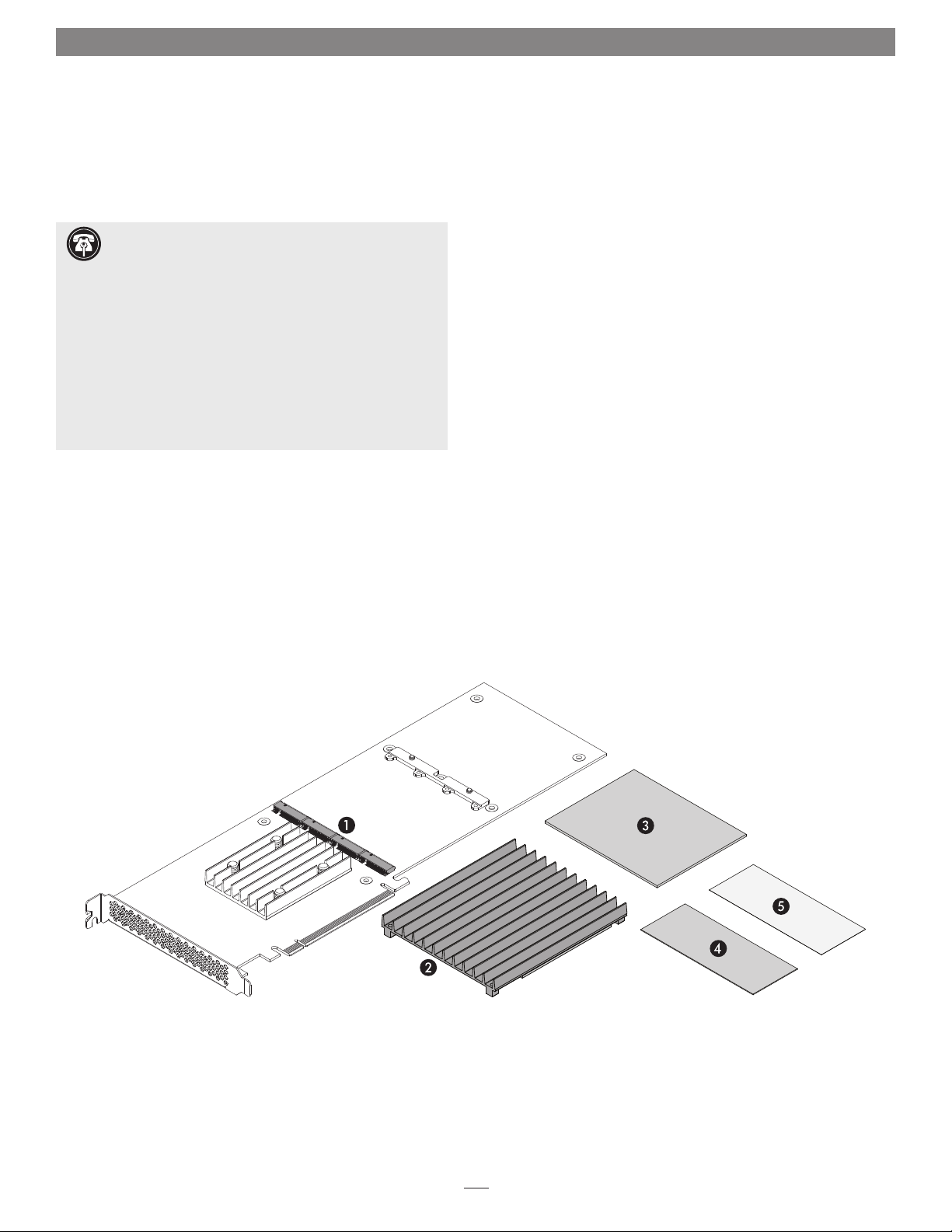
Card Description
1 – M.2 SSD Sockets
The Sonnet M.2 4x4 PCIe Card supports the installation
of four single- or double-sided M.2 2280 NVMe PCIe SSDs
with “M” key connectors. When configuring them as RAID
volumes, Sonnet recommends the use of identical SSDs.
2 – SSD Heatsink
Backed with a thermal transfer pad that contacts the SSDs’
components, the heatsink conducts heat away from the SSDs.
3 – Thermal Transfer Pad (Thickest, Full-Size)
Apply this to the card when you install single-sided SSDs;
instructions follow.
4, 5 – Thermal Transfer Pads (Medium and Thin, Half-Size)
Apply these to the card when you install double-sided SSDs;
instructions follow.
2
Page 3
SSD and Card Installation Steps
Support Note: When handling computer
products, you must take care to prevent
components from being damaged by static electricity.
Before opening your computer or removing parts
from their packages, always ground yourself first by
touching a metal part of the computer, such as a
port access cover, and work in an area free of static
electricity; avoid carpeted areas. Handle all electronic
components by their edges, and avoid touching
connector traces and component pins.
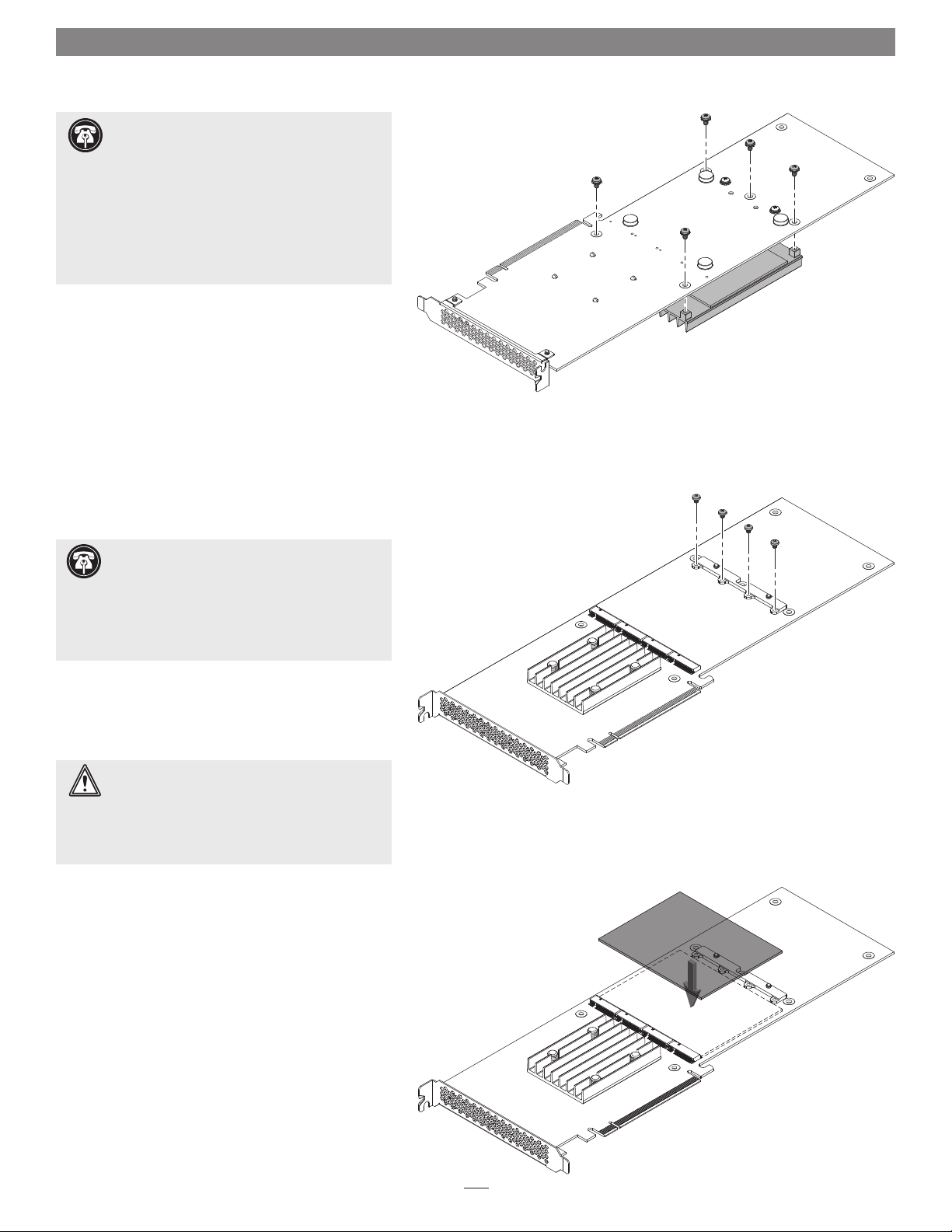
1. Handling the card by its edges, remove the Sonnet
M.2 4x4 PCIe Card from its packaging.
2. Place the card upside-down on a flat, level surface
(Figure 1).
3. Using a Phillips screwdriver, remove the five screws
securing the heatsink to the card (Figure 1). Set
aside the screws.
4. Flip the card over, and then remove the four screws
as shown (Figure 2). Set aside the screws.
Figure 1
Support Note: The earlier version of this
product shipped with a full-size thermal transfer
pad pre-attached (and no separate pads included in
the package), limiting compatibility to single-sided
SSDs (components on one side only). If this is the case
with your card, please skip to step 21 to complete the
SSD installation.
WARNING: You are required to install either one
or two thermal transfer pads on the M.2 4x4
PCIe Card before installing SSDs. It is critical that you use
the correct pad or pads, determined by the type of SSDs
you install. Using the wrong pad(s) may result in poor
performance, or may possibly damage the card.
5. Determine whether you are installing single- or
double-sided SSDs (components on one or both
sides). If you are installing single-sided SSDs,
remove the thickest, full-size thermal transfer pad
from its packaging. Otherwise, skip to step 12.
6. Carefully peel off the backing material from one
side of the pad.
Figure 2
7. Starting with one edge, carefully apply the pad
to the card between the SSD sockets and retainer
screw screw holes; make sure to avoid trapping air
bubbles (Figure 3).
8. Rub the pad all over to ensure good contact with
the card (Figure 3).
Figure 3
3
Page 4

SSD and Card Installation Steps
9. Peel off and set aside the backing material from the
top of the pad you just installed (Figure 4).
10. If you are installing four SSDs now, skip to step 21.
Otherwise, cut the backing material as shown,
removing 1/4 of the sheet when installing one or
three SSDs, or 1/2 of the sheet when installing two
SSDs (Figure 5).
backing
material
cut here when installing
two SSDs
Figure 4
11. Reapply the cut backing material to the thermal
transfer pad as shown where no SSD(s) will be
installed (Figure 6). By reapplying the backing
plastic, you are protecting the sticky thermal pad
from collecting dust, and the thermal pad will
be clean when you are ready to install additional
SSDs. Note that this example shows preparation for
installing only one SSD.
Skip to step 21.
covers sticky thermal pad
where no SSD(s) installed
4
cut here when installing
one or three SSDs
Figure 5
stick y therma l pad
expose d where
SSD(s) inst alled
Figure 6
Page 5

SSD and Card Installation Steps
12. Assuming you are installing double-sided SSDs,
remove the half-size thermal transfer pads from
their packaging.
13. Carefully peel off the backing material from one
side of the medium thickness pad.
14. Starting with one edge, carefully apply the pad to
the card next to the SSD sockets as shown; make
sure to avoid trapping air bubbles (Figure 7).
15. Carefully peel off the backing material from one
side of the thinnest pad.
16. Starting with one edge, carefully apply the pad to
the card between the already-applied pad and the
retainer screw screw holes as shown; make sure to
avoid trapping air bubbles (Figure 7).
17. Rub the thermal transfer pads all over to ensure
good contact with the card (Figure 7).
18. Peel off and set aside the backing material from the
top of the pads you just installed (Figure 8).
medium
pad
backing
material
thin
pad
Figure 7
19. If you are installing four SSDs now, skip to step 21.
Otherwise, cut the backing material as shown,
removing 1/4 of each sheet when installing one
or three SSDs, or 1/2 of each sheet when installing
two SSDs (Figure 9).
Figure 8
cut here when installing
two SSDs
cut here when installing
one or three SSDs
5
Figure 9
Page 6

SSD and Card Installation Steps
20. Reapply the cut backing material to the thermal
transfer pads as shown where no SSD(s) will be
installed (Figure 10). By reapplying the backing
plastic, you are protecting the sticky thermal pad
from collecting dust, and the thermal pad will
be clean when you are ready to install additional
SSDs. Note that his example shows preparation for
installing only one SSD.
21. Handling it by its edges, remove an SSD from its
packaging.
covers sticky thermal pad s
where no SSD(s) installed
stick y therma l pads
expose d where
SSD(s) inst alled
Figure 10
22. Insert the SSD into one of the SSD sockets (where
the thermal transfer pad or pads’ sticky side is
exposed) until it snaps into place (Figure 11).
23. Repeat steps 21 and 22 with any remaining SSDs
left to install (Figure 11).
24. Using screws you removed previously, secure the
SSD(s) to the card (Figure 12); do not overtighten
the screws. If you installed fewer than four SSDs,
reinstall remaining screws into the open holes.
Figure 11
Figure 12
6
Page 7

SSD and Card Installation Steps
Support Note: If you have the earlier version
of this product that shipped with a thermal
transfer pad pre-attached to the card, please skip to
step 28 to complete the installation.
25. Peel off and set aside the backing material to
expose the sticky side on the thermal transfer pad
attached to the heat sink (Figure 13).
26. If have installed four SSDs, skip to step 28.
Otherwise, cut off 1/4 of the backing material
sheets as shown if you installed one or three
SSDs, or cut off 1/2 of the backing material if you
installed two SSDs (Figure 14).
backing
material
cut here when installing
two SSDs
Figure 13
27. Reapply the cut backing material to the heatsink’s
thermal transfer pad as shown where no SSD(s)
were installed (Figure 15). By reapplying the
backing plastic, you are protecting the sticky
thermal pad from collecting dust, and the thermal
pad will be clean when you are ready to install
additional SSDs.
This example shows reapplying the backing
material when only one SSD was installed. Note
the location of the threaded screw holes on the
heatsink; the side with two holes covers the SSD
sockets.
covers sticky
thermal pad
where no SSD(s)
installed
7
cut here when installing
one or three SSDs
Figure 14
stick y therma l pad
expose d where
SSD(s) inst alled
Figure 15
Page 8

SSD and Card Installation Steps
28. Set the heatsink on top of the SSDs, aligning
the threaded holes in the heatsink with the
corresponding holes in the card as shown
(Figure 16). Note that there are three holes on one
side and two on the other.
29. Holding the heatsink firmly against the card, flip
over the Sonnet M.2 4x4 PCIe Card (Figure 17).
30. Secure the heatsink to the card with the five screws
you removed previously (Figure 17); do not
overtighten the screws.
Card Installation Steps
1. Shut down your computer or expansion chassis,
disconnect its power cable, and then open it to
access the expansion card area (PCI Express slots);
refer to the user manual for specific information
Figure 16
Figure 17
2. Locate an available x16 PCIe slot and remove its
access cover if necessary.
3. Install the Sonnet card with attached SSDs into
the slot; make sure the card is firmly seated and
secured (use the computer’s PCIe card retaining
latch on the slot if present).
4. Close your computer or expansion chassis.
5. Reconnect the computer’s power cable.
8
Page 9

SSD Formatting and Configuration, and Support Information
Formatting SSDs
macOS:
Use Disk Utility (found in the Utilities folder within the
Applications folder) to format installed SSDs.
Support Note for Mac Users: mac OS 10.14.6+
supports both 512 and 4k block size SSDs, but macOS
10.13.6 supports only 4k block size SSDs. SSDs 1TB or larger are
shipped from the factory programmed with a 4k block size. If you
have smaller SSDs that are programmed with 512 block size, and
you need to be compatible with macOS 10.13.6, you may need to
reprogram your SSDs to a 4k block size. Go to www.sonnettech.
com/support/kb/kb.php, navigate to the support page for Sonnet
M.2 4x4 PCIe Card, and then open the FAQ about Programming
SSDs to 4k Block Size for Compatiblity With macOS 10.13.6 for more
information.
Windows:
If you intend to format SSDs connected to the Sonnet card using
Windows drive formatting tools (Disk Management), you may
locate instructions by using “format volume”, and “create striped
volume” as search items in Windows Help.
Linux
Use the tools or utilities you would normally use to format
internal drives.
RAID Configuration Support Information
macOS:
Sonnet M.2 4x4 PCIe Card supports RAID 0, RAID 1, and
concatenated disk set configurations of SSDs under macOS
10.14.6 and later. Additionally, RAID 5 configuration is supported
via third party software (sold separately).
Contacting Customer Service
The Sonnet Web site located at www.sonnettech.com has the
most current support information and technical updates. Before
contacting Customer Service, please check our Web site for the
latest updates and online support files, and check this Quick Start
Guide for helpful information.
Email support requests generally receive the fastest responses, and
are usually processed within a 24-hour period during normal
business hours, excluding holidays. When you contact Customer
Service, have the following information available so the customer
service staff can better assist you:
• Product name
• SSD model(s)
• Computer model
• OS version
• A System Report (macOS), or a Microsoft System Information
MSINFO32 (Windows) report (Windows), along with a
description of the issue(s) you are encountering with your device
If further assistance is needed, please contact Sonnet Customer
Service at:
E-mail: support@sonnettech.com
Tel : 1-949-472-2772
(Monday–Friday, 9 a.m.–5 p.m. Pacific Time, excluding holidays)
Japan Customers
Contact Sonnet Customer Service Japan at:
E-mail: jp.support@sonnettech.com
Windows:
Sonnet M.2 4x4 PCIe Card supports RAID 0, RAID 1, RAID 5,
and concatenated disk set configurations of SSDs.
Linux:
Sonnet M.2 4x4 PCIe Card supports RAID 0, RAID 1, RAID 5,
and concatenated disk set configurations of SSDs.
Booting From Attached SSDs
macOS:
Sonnet M.2 4x4 PCIe Card supports booting from individual
(non-RAIDed) SSDs when the card is installed in Mid 2010, Mid
2012, and 2019 Mac Pro computers, plus Thunderbolt-to-PCIe
card expansion systems. Please note that in some cases it may be
necessary for you to hold the option key during a start, and then
select the startup disk attached to the Sonnet card.
If the Fusion card is installed in a Thunderbolt chassis, and you
are using a Mac with the Apple T2 Security Chip, then you must
enable External Boot in the Startup Security Utility.
Windows and Linux:
Sonnet M.2 4x4 PCIe Card does not support booting in computers
running Windows or Linux.
9
Page 10

©2020 S onnet Tech nologies, Inc . All rights rese rved. S onnet and the Son net logotype are t radem arks of S onnet Tech nologies, Inc . Mac, t he Mac log o, macOS a nd Mac Pro a re trade marks
of Apple Inc., registered in th e United States and othe r countr ies. Thunderbolt and th e Thunde rbolt logo are trademar ks of Int el Corpo ration in the U. S. and/or other countrie s. Other
product names are trademark s of their respec tive owners. Product spe cification s subjec t to chan ge witho ut notice. QS- FUS -SS D-4X4-E3S-E-E-072220
 Loading...