

Page 1

Configuration Tool and Utilities v3.21
Operation Manual
for Fusion RAID Storage Systems
Page 2

Page 3

Contents
1.0 ATTO Configuration Tool Overview............................................................................................. 1
About the Configuration Tool
Configuration Tool Launch
ATTO Configuration Tool Navigation
1.1 NVRAM Settings........................................................................................................................ 7
SAS Address
Boot Driver
Heartbeat
Device Wait Time
Device Wait Count
Spinup Delay
1.2 RAID Settings........................................................................................................................... 9
Preliminary Configuration Steps
DVRAID RAID Group Setup
Custom RAID Group Setup
Mac OS Drive Formatting
Windows Drive Formatting
Hot Spares Usage
RAID Group Management Overview
RAID Group Capacity Expansion
RAID Level Migration
RAID Group Deletion
RAID Group Rebuilding
1.3 Drive and RAID Group Monitoring............................................................................................ 17
Basic Drive Information
Detailed Drive Information
RAID Group Information
Individual Drive Identification
S.M.A.R.T. Data Monitoring
S.M.A.R.T. Monitoring Enabling and Disabling
S.M.A.R.T. Status Checking
S.M.A.R.T. Attribute Filtering
S.M.A.R.T. Notifications
Page 4

Contents
1.4 Notifications......................................................................................................... 21
Basic Alerts
Logging
E-Mail Alert
1.5 Diagnose and Replace a Faulted Drive................................................................................ 23
Faulted Drive Identification
Faulted Drive Replacement
1.6 Configuration Tool Troubleshooting.......................................................................................... 25
Messages from NVRAM Tab Actions
An error occurred loading NVRAM data.
Warning: NVRAM could not be read, defaults returned.
An error occurred updating the NVRAM.
Feature bounds checking
Messages from Flash Tab Actions
This is not a flash file, or it is corrupt.
This HBA is not compatible with the selected flash file.
A valid file was not selected.
An error occurred reading from the flash file, the file may be corrupt.
An error occurred updating the flash.
The card has been prepared for firmware updating…
2.0 Windows Only - ATTO Disk Benchmark..................................................................................... 27
Benchmark Fields
Radio Button Group
Multiple Benchmark Testing
2.1 ATTO Disk Benchmark Troubleshooting..................................................................................... 29
Appendix A - CLI ASCII-Based Interface........................................................................................... i
CLI Error Messages
CLI Summary
CLI Command Explanations
Appendix B - Quick Format Instructions........................................................................................ xii
Mac OS Users’ Instructions
Windows Users’ Instructions
Page 5
1.0 ATTO Configuration Tool Overview
About the Configuration Tool
The ATTO Configuration Tool is a utility program that displays
information about installed controllers, drivers and drives, and
provides a mechanism to configure installed controllers.
This program executes under:
• Mac OS X 10.4 or later
• Windows Vista /XP/Server 2003/2000
• Linux 2.6 kernel, x86 and x64
Note: Java version 1.5 or later must be installed.
The ATTO Configuration Tool displays:
• The name of the Sonnet RAID controller (
Rxxx adapter)
• Information about the drivers controlling the Sonnet RAID
controller, including version information for both the currently
executing driver and the flash image
• Information about drives attached to the Sonnet RAID controller
You may use the Configuration Tool to:
• Manage RAID groups
• Configure RAID Event notifications
• Modify the RAID controller’s NVRAM settings
• Revert to default factory settings
• Update the RAID controller’s flash image
• Update firmware on huge disk arrays
The factory settings on your Sonnet RAID controller should
provide excellent performance for a wide range of applications.
However, some applications may benefit from modification of
the controller’s NVRAM settings that tune the controller for a
specific performance range.
listed as an ExpressSAS
Configuration Tool Launch
1. Locate the application icon in the folder created during
installation.
2. Double-click the ATTO Configuration icon to start the
application.
WARNING: Back up system data when installing or
changing hardware configurations.
Note: The Sonnet RAID controller is designed to operate properly using
factory settings. Entering invalid or incorrect NVRAM settings
may cause your Sonnet RAID controller to function incorrectly.
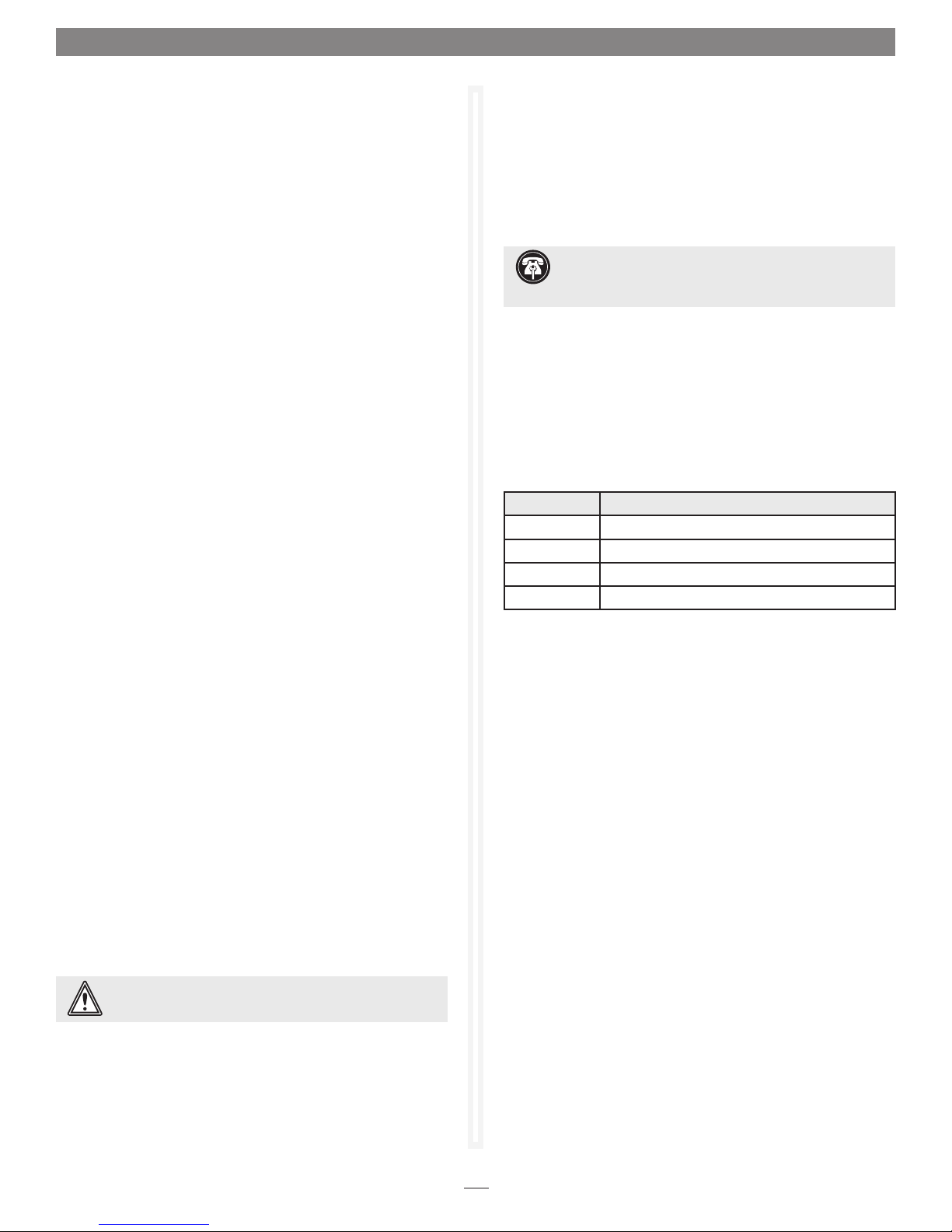
The main screen has three panes: Device Listing, Configuration
Options and Status. See
Figure 1 on page 3.
ATTO Configuration Tool Navigation
The Device Listing pane at the left of the window lists all devices
(controllers and drives) currently connected to the system.
Expand the device tree to reveal additional detail on connected
devices.
Support Note: In the Device Listing pane of the ATTO
Configuration Tool window, the Sonnet RAID controller is
identified as an ExpressSAS Rxxx.
The Configuration Options pane provides information and
options for a device highlighted in the device listing.
If you highlight a device in the
panes are displayed for that device.
The following chart specifies the tabs that are displayed for the
indicated device type.
Tree Node Tab(s) Displayed
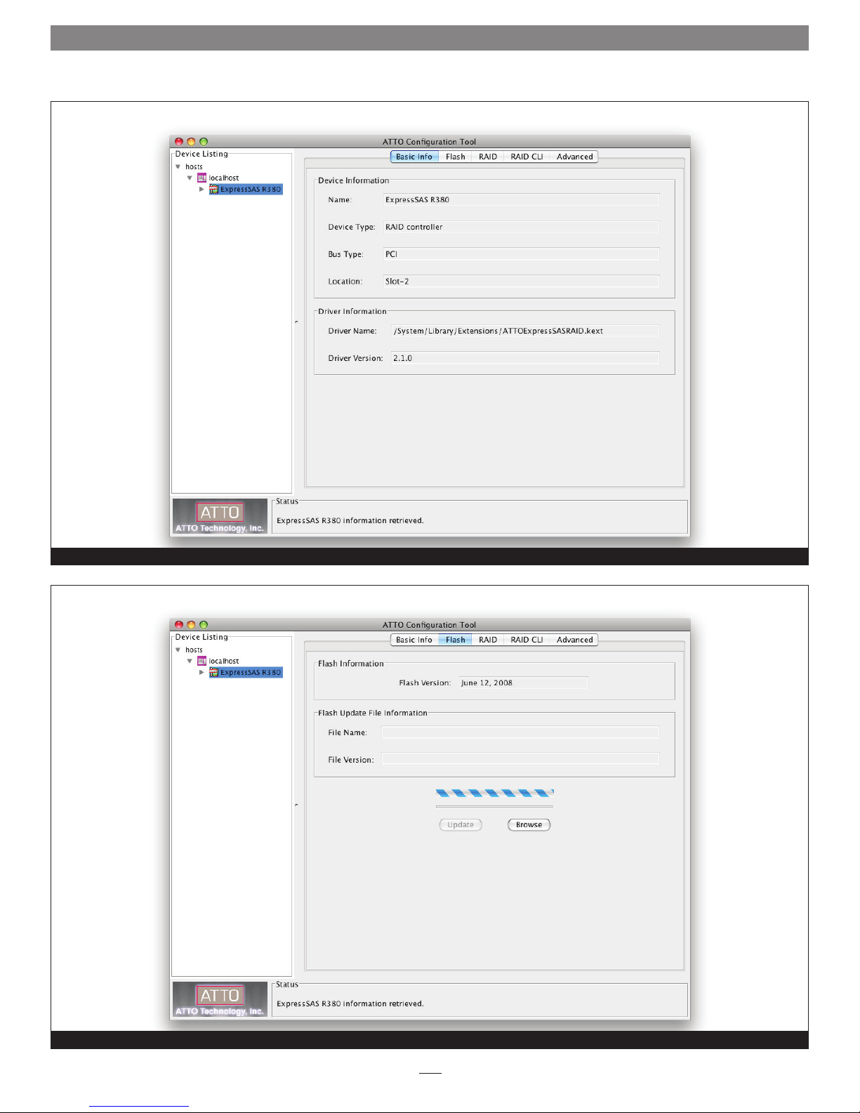
Controller Basic Info, Flash, RAID, RAID CLI, Advanced
Channel NVRAM, PCI Info
RAID Groups Basic Info, Flash
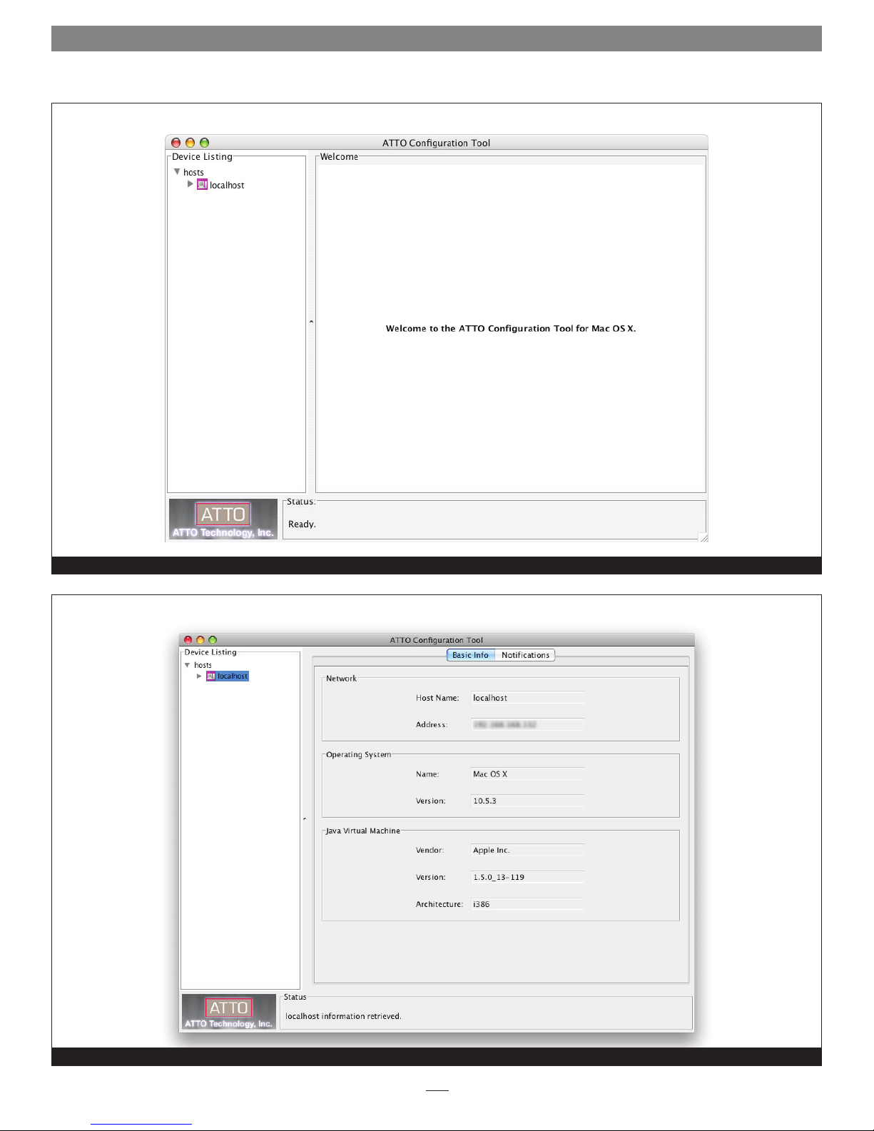
Local Host Basic Info, Notifications
The following tabs are displayed in the Configuration Options
pane when you select a specific controller in the Device Listing
pane.
• The
Basic Info tab provides information about the Sonnet
RAID controller when it is highlighted in the Device Listing
pane, or the computer if localhost is highlighted. You cannot
make changes from these screens. See
Figure 3 on page 4.
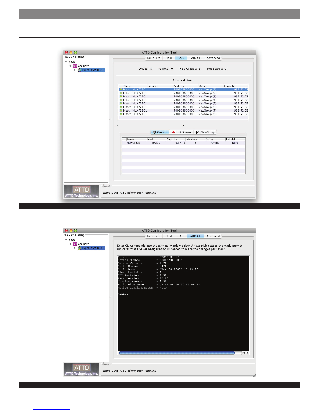
Flash tab provides information about the current flash
• The
version programmed on the highlighted controller. See
4 on page 4.
Click the Browse button at the bottom of the tab to search for
new flash files on your system such as FlashBundle_2007_02_
27.R380.
Once you’ve selected the flash file, click the Update button to
automatically update your Sonnet RAID controller.
• The
their RAID group and hot spare associations, and their
operating status. See
• The
interface, which, as an alternative to application menu-based
commands, enables the use of ASCII-based commands to control
configuration and diagnostic tasks. See
RAID tab provides information about attached drives,
RAID CLI tab provides access to the command line
Device Listing pane, tabs and
Figure 2 on page 3 and
Figure
Figure 5 on page 5.
Figure 6 on page 5.
1
Page 6

1.0 ATTO Configuration Tool Overview
ATTO Configuration Tool Navigation (continued)
• The Advanced tab does not function with the Sonnet RAID
controller; clicking this tab merely displays a message.
• When you select a specific channel under the Sonnet RAID
controller in the Device Listing pane, the
the NVRAM parameters applicable to the Sonnet RAID
controller and channel selected. Refer to NVRAM Settings on
page 7, and Configuration Tool Troubleshooting on page 25
for information about NVRAM settings.
• The Sonnet RAID controller’s information is displayed in the
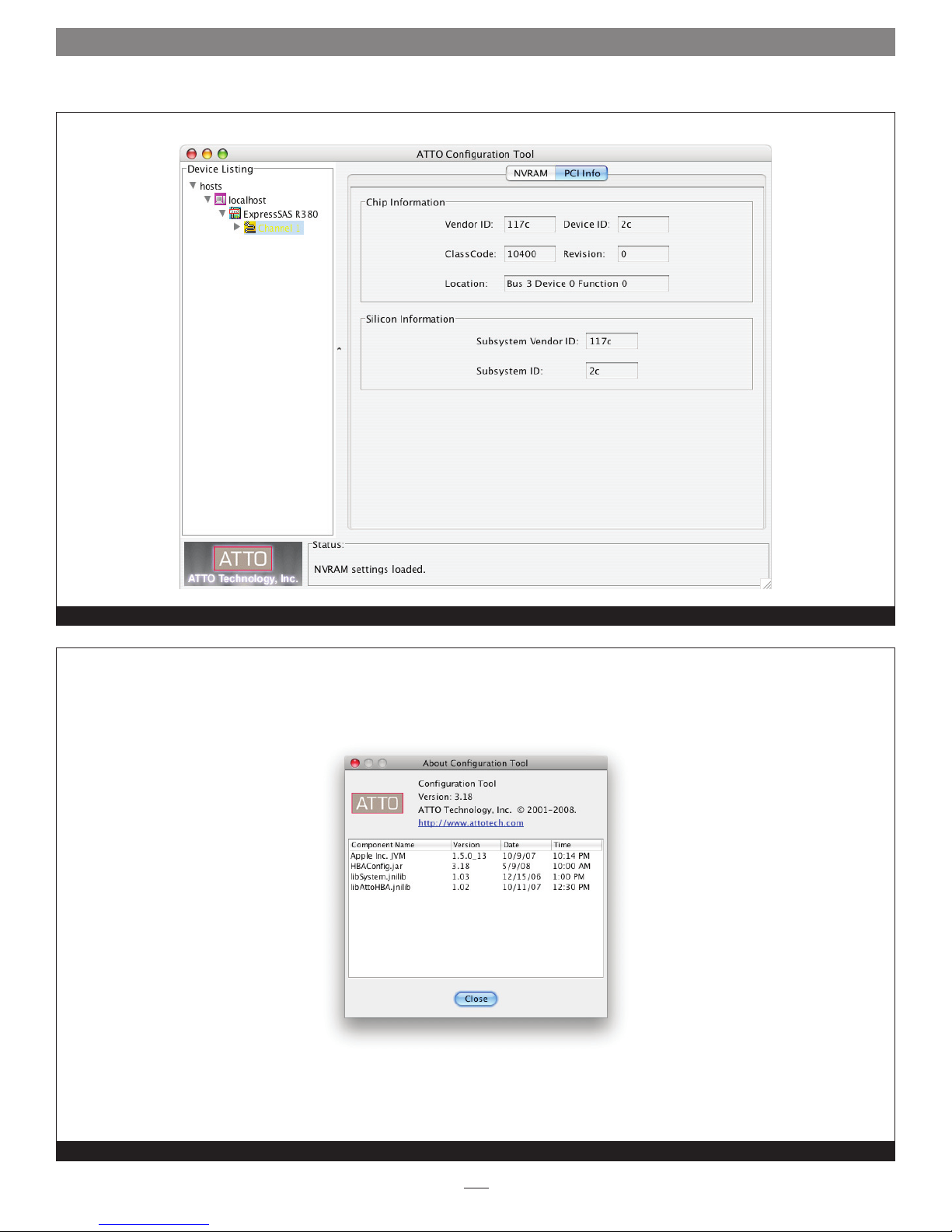
PCI Info tab. See Figure 7 on page 6.
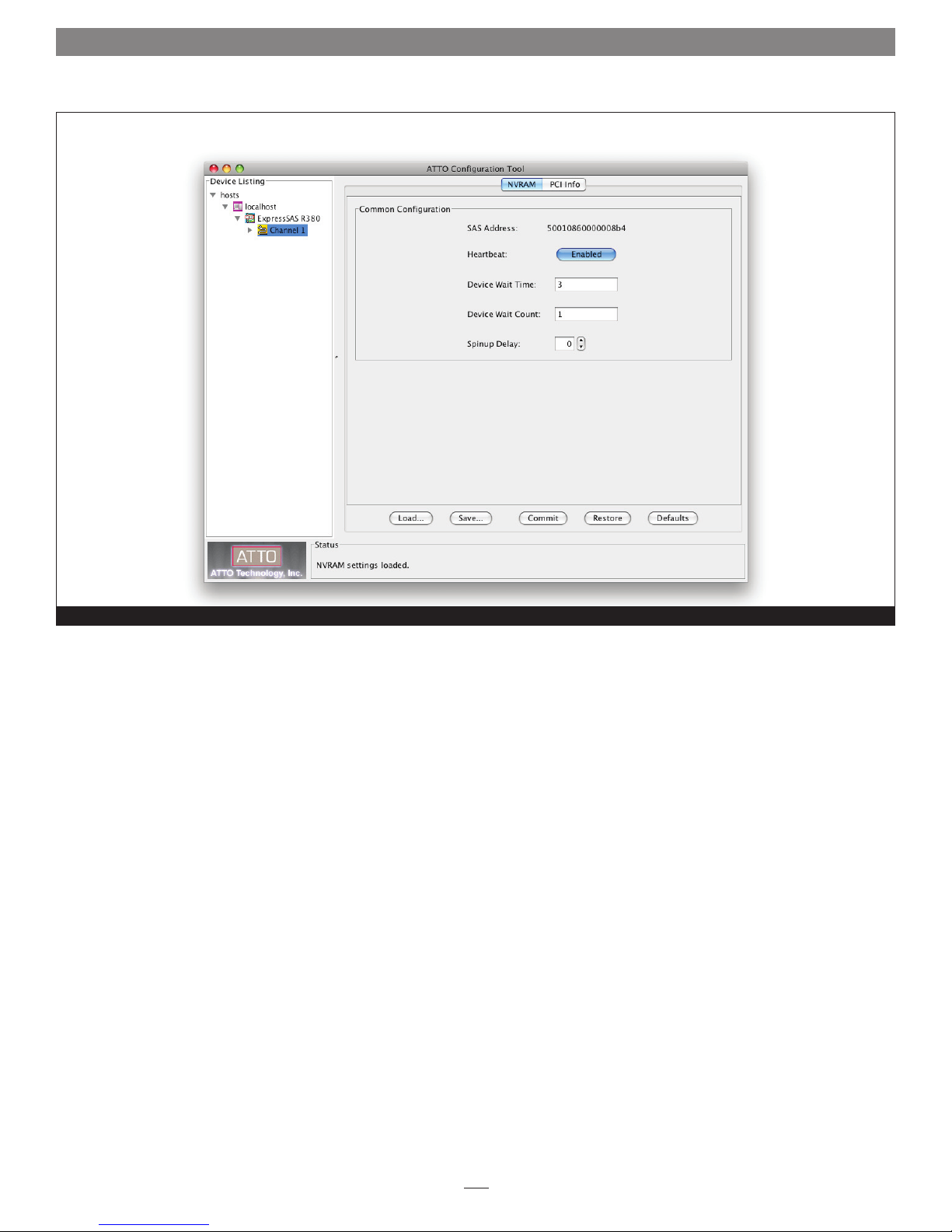
NVRAM tab displays
• The current status of the
the
Status pane at the bottom of the window.
About window
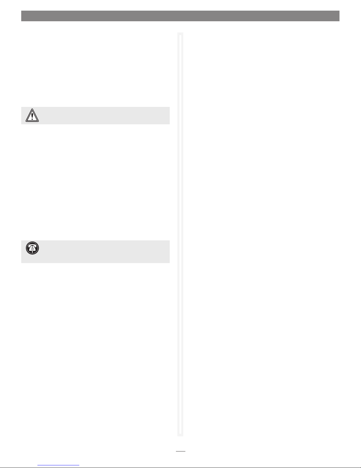
The
About window, displayed when About is selected from the
Help menu, lists the ATTO Configuration Tool’s version number.
See
Figure 8 on page 6.
Configuration Tool is represented in
2
Page 7
1.0 ATTO Configuration Tool Overview
Opening Screen
Figure 1
Basic Info tab when Local Host chosen in the Device Listing pane
Figure 2
3
Page 8
1.0 ATTO Configuration Tool Overview
Basic Info tab when the Sonnet RAID controller is chosen in the Device Listing pane
Figure 3
Flash tab when the Sonnet RAID controller is chosen in the Device Listing pane
Figure 4
4
Page 9
1.0 ATTO Configuration Tool Overview
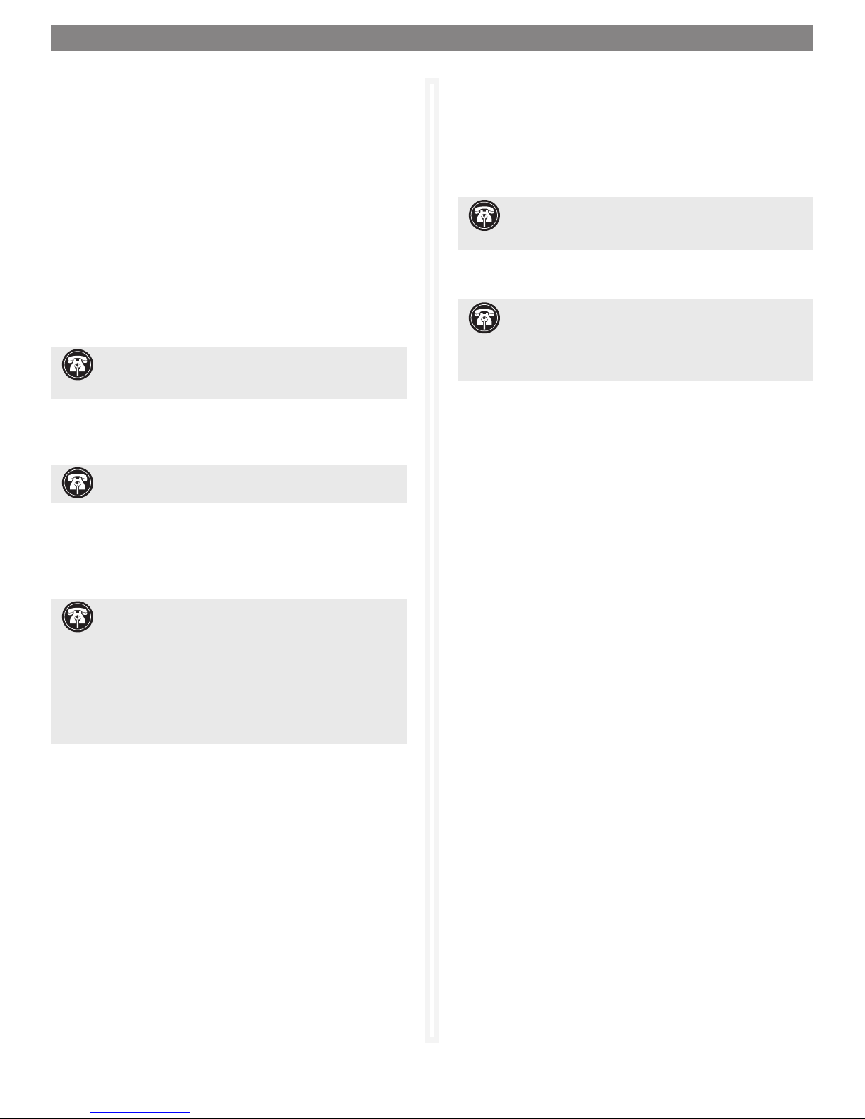
RAID tab when the Sonnet RAID controller is chosen in the Device Listing pane
Figure 5
RAID CLI tab when the Sonnet RAID controller is chosen in the Device Listing pane
Figure 6
5
Page 10
1.0 ATTO Configuration Tool Overview
PCI Info tab
About Configuration Tool window
Figure 7
Figure 8
6
Page 11
1.1 NVRAM Settings
The settings in the NVRAM tab vary depending upon the operating
system.
The Sonnet RAID controller is designed to operate properly using
factory settings. Entering invalid or incorrect settings when using
an NVRAM configuration utility such as the ATTO Configuration
Tool may cause your controller to function incorrectly. See
Figure 9 on page 8.
WARNING: Back up system data when installing or
changing hardware configurations.
Use caution when making changes to NVRAM settings and only
make changes to those with which you are familiar. Once you
have made the desired changes, click Commit to save the changes.
Click Save to name and save an NVRAM configuration. Click Load
to load a saved NVRAM configuration.
until you reboot the system.
If you do not want to make any changes, you may choose one of
the following
Defaults: restores the controller to factory default settings. The
•
Commit button must be clicked to save any changes.
Changes do not take effect
Device Wait Time
Choices: 1–255 seconds
Default: 3
Specifies the number of seconds that the driver waits for devices
to appear.
Device Wait Count
Choices: 1–255 devices
Default: 1
Specifies the number of devices that must appear in order to cancel
the Device Wait Time period.
Spinup Delay
Choices: 0-20 seconds
Default: 0
Specifies the number of seconds each SAS port waits for disk drives
to spin up.
Restore: reverts to the NVRAM settings saved the last time the
•
Commit button was used. Clicking Commit is not necessary.
Support Note: The SAS address is a globally-unique
identifier assigned to devices such as the Sonnet RAID
controller, and is similar to an Ethernet adapter’s MAC address.
SAS Address
Read only
Displays the SAS address assigned to the controller. The value
cannot be modified.
Boot Driver (Windows only)
Choices: enabled, scan only, disabled
Default: disabled
If enabled and disk drives are detected during the bus scan, the
BIOS driver remains resident. If disabled, the BIOS starts, resets
the controller chip and unloads the driver.
If
Scan Only is selected, the BIOS driver scans the bus and displays
the devices attached, then unloads itself after a brief delay.
Heartbeat
Choices: enabled, disabled
Default: enabled
When enabled, the Sonnet RAID controller‘s firmware is required
to respond to periodic activity. If the firmware does not respond,
the system driver resets the firmware on the controller.
7
Page 12
1.1 NVRAM Settings
NVRAM settings tab
Figure 9
8
Page 13
1.2 RAID Settings
Support Note: In Fusion RAID systems shipped from
Sonnet with hard drives installed, the drives are formatted
Mac OS Extended (Journaled), and configured as a single RAID
5 RAID group. If you need to change the configuration, use the
ATTO Configuration Tool and the operating system software tools
to reformat and reconfigure the drives. See page xii for Quick
Format instructions for Mac OS and Windows users.
The ATTO Configuration Tool provides the capability to configure disk
storage into RAID groups or Hot Spare drives.
Note: Even an individual JBOD disk is considered to be a RAID group.
Use the ATTO Configuration Tool to set up RAID groups on your
Sonnet RAID controller in one of the following RAID levels:
• JBOD
• RAID Level 0
• RAID Level 1
• RAID Level 4
• RAID Level 5
• RAID Level 6
• RAID Level 10
• DVRAID
Support Note: DVR AID is a customized, protected
RAID 4 configuration. It is optimized for increased digital
video playback performance when compared to that obtained
from a RAID 5 configuration. DVRAID’s write per formance is
decreased in order to accomplish this optimization.
DVRAID RAID groups may be set up automatically by the ATTO
Configuration Tool. All other RAID configurations require
customized input.
Each RAID group may be divided into one or more partitions;
each partition appears to the host operating system as a virtual
disk.
Windows Support Note: In order to create RAID
volumes larger than 2TB under Windows, you must do one
of the following: Select the 4KB sector size when creating
a custom RAID group (not DVRAID). -OR- Use the software
configuration tools included with the Fusion storage to create
volumes up to 2TB, concatenate (link together in a virtual chain)
the volumes, and then format as NTFS. -OR- Use GPT formatting.
Note that drives and volumes with GPT formatting are not visible
to any version of Windows XP Professional, nor to the 32-bit
version of Windows Server 2003 SP1.
You may use the command line interface pane from the
RAID
CLI tab in the ATTO Configuration Tool to set up or modify
various parameters (Refer to Appendix A).
However, the menubased procedures listed in this chapter are the preferred
procedures for setting up RAID configurations for the Sonnet
RAID controller.
Preliminary Configuration Steps
1. Launch the ATTO Configuration Tool application.
2. The Configuration Tool main screen appears. See Figure 10
on
page 12 for an overview of the screen. In the Device
Listing pane on the left side of the window, click ExpressSAS
Rxxx under
Support Note: In the Device Listing pane of the ATTO
identified as an ExpressSAS Rxxx.
localhost.
Configuration Tool window, the Sonnet RAID controller is
3. Click the RAID tab; attached drives are displayed in the top
pane, while RAID groups and Hot Spares are displayed in the
bottom pane.
DVRAID RAID Group Setup
The DVRAID wizard automatically sets up a DVRAID RAID
group using all available drives attached to the Sonnet RAID
controller. If you do not want all available drives set up in a
DVRAID RAID group, either remove the drives from the drive
enclosure, or select Custom RAID setup.
WARNING: After selecting the DVRAID, R AID 4, RAID 5,
or RAID 6 option, configuration of a set of eight 1TB
drives can take up to 4 hours (or up to 2 hours with 500GB
drives).
1. After completing Preliminary Configuration Steps on this
page, select RAID Management > Create Group > DVRAID
Setup from the application menu.
2. A dialog window will pop up, asking whether you want
to perform an Express Setup Operation of DVRAID; click
Yes. The ATTO Configuration Tool automatically uses all
unassigned drives to create a DVRAID RAID group. While the
RAID group is being created, a message box displays and the
panes display the RAID groups.
3.
The RAID group must still be formatted by your computer’s
operating system software before it becomes available for use.
For Mac users, use Disk Utility; for Windows users, use Disk
Management. For more information on drive formatting, see
Mac OS Drive Formatting or Windows Drive Formatting on
page 11.
4. After formatting, RAID groups may be used during the setup
operation, but performance is limited until setup is complete.
9
Page 14
1.2 RAID Settings
Custom RAID Group Setup
1. After completing Preliminary Configuration Steps on page 9,
select RAID Management > Create Group > Customized
from the application menu.
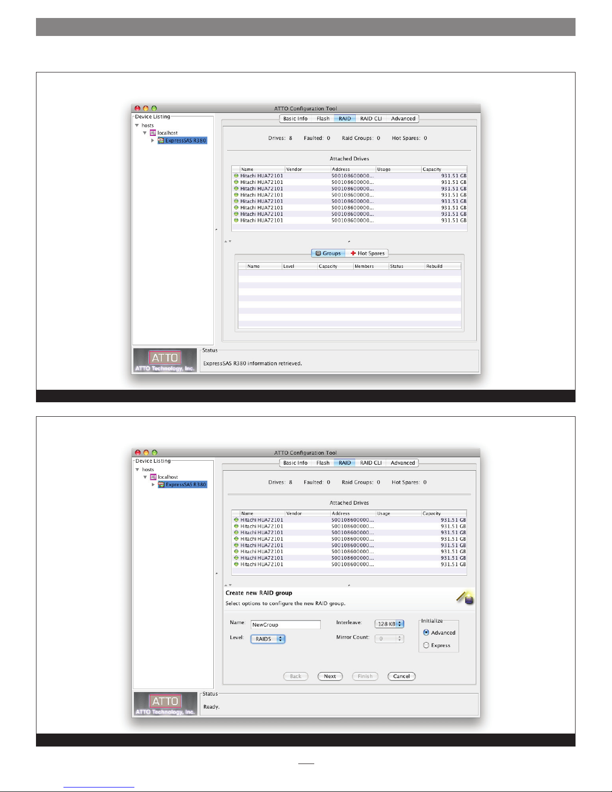
2. Select the first set of options to configure the new RAID
group. See
Name: name the RAID group or use the one assigned by
•
the Configuration Tool. The name must be unique and no
more than 14 characters.
•
Level: select a RAID group level from the drop-down box.
Support Note: Descriptions of basic RAID levels can be
address: http://en.wikipedia.org/wiki/RAID#Standard_levels
• Interleave: select an interleave value. The default value is
64 KB.
Support Note: The interleave value of 128KB offers the
• Mirror Count: select the number of mirror groups when
RAID 1 or RAID 10 RAID groups are created.
Figure 11 on page 12.
found on the Wikipedia.org Web site at the following
best performance for most SATA drives.
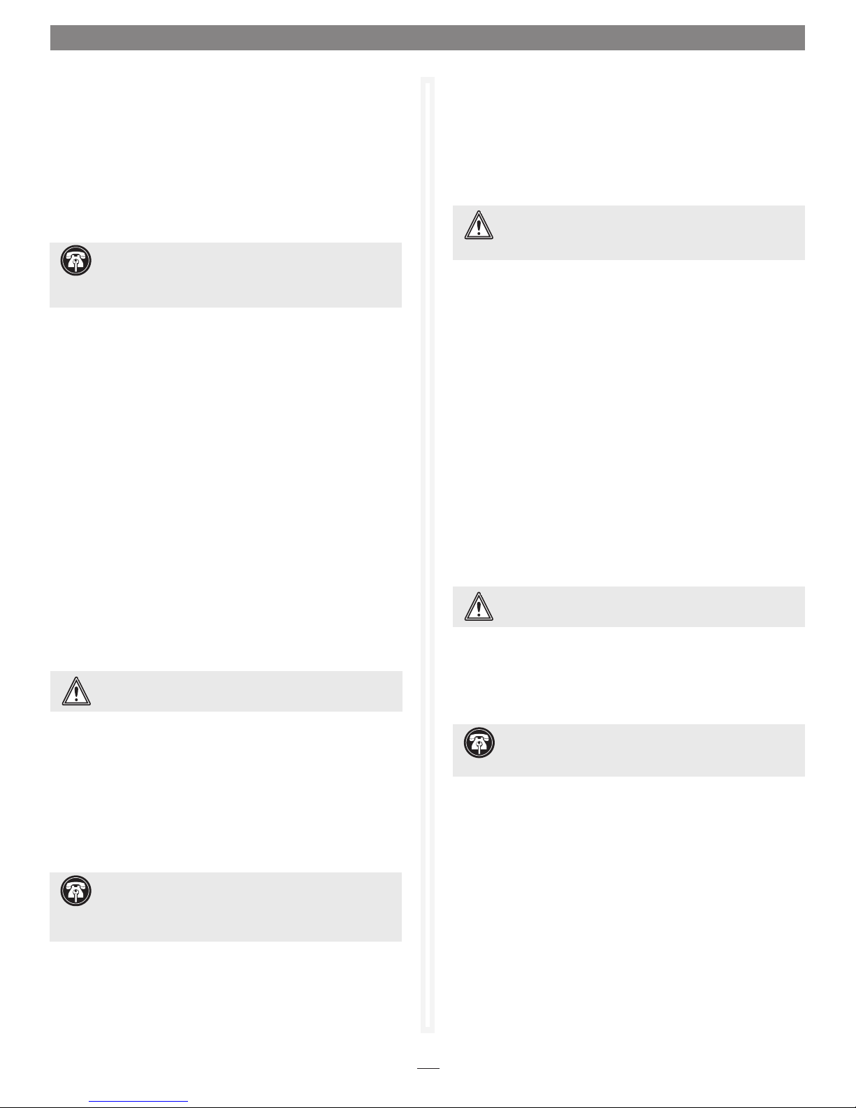
4. Click
•
Next. Select the next set of options to configure the
new RAID group. See
Figure 13 on page 13.
Sector Size: select a sector size from the drop down box.
The default is 512 bytes.
Windows Support Note: Choosing the 4K sector size
enables the creation and use of R AID volumes larger than
2TB on systems running Windows XP 32-bit.
• Speed Read: select Always, Adaptive, or Never. The default
is Adaptive.
Support Note: For the Speed Read option, select Always
if you expect to work with large sequential files (video, for
example), Never if you expect most of the files are smaller in size
(general storage, database, etc.), or Adaptive if you expect mixed
use or don't know.
•
Rebuild Priority: select High, Same, or Low. The default is
Low.
Auto Rebuild: on or off.
•
5. If you want the RAID group to be presented as one virtual
disk (partition), click Finish. If you want more than one
virtual disk (partition), click
Next (see Figure 14 on page 14),
and then select one of the following options:
• Initialize: select Advanced or Express.
Support Note: When the Advanced Initialize option is
selected, parity blocks are calculated and the RAID group
is thoroughly scanned and subjected to a complete Write/Verify
operation to map out any bad blocks on the drives before the
RAID group is made available for use.
When the Express Initialize option is chosen, drives are not
scanned and subjected to the Write/Verify operation, but parity
blocks are calculated and the RAID group may be used during
the initialization.
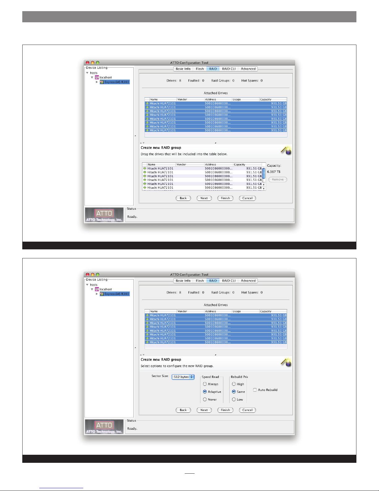
3. Click Next. Select the drives in the top pane and drag them
into the device area in the bottom pane. See
Figure 12 on
page 13.
• leave as one partition
• partition by count
• partition by size
If you choose to split the RAID group by count or capacity,
you must enter additional information.
6. If you have not already done so, click
Finish.
7. A confirmation dialog box asks you to approve the
configuration you have chosen. Click
Yes. See Figure 15 on
page 14.
8. Every RAID group must be formatted by your computer’s
operating system software before it becomes available for use; Mac
users will use Disk Utility, while Windows users will use Disk
Management. For more information on drive formatting, see
Mac OS Drive Formatting or Windows Drive Formatting on
page 11.
10
Page 15

1.2 RAID Settings
Mac OS Drive Formatting
1. Depending on how you configure your setup, a Disk Insertion
window stating that there is an unreadable volume will
appear at some point during the RAID group creation process;
click Initialize, and then Disk Utility will open.
2. In the
3. Click the Erase button; a window will appear asking you to
4. Repeat steps 2 and 3 for each remaining unformatted RAID
5. Depending on how you configured the RAID groups, the
Disk Utility window, each RAID group you created
using the ATTO Configuration Tool will appear as a single
volume. Select the volume, and then click the Erase tab at the
top of the window.
approve your choice; click Erase.
group, and then close Disk Utility.
volumes may already be mounted and present on the desktop.
If you created a DVRAID, RAID 4, RAID 5, or RAID 6 RAID
group, configuration will take much longer. You may check
on the process by double-clicking the volume name in the
lower pane of the
ATTO Configuration Tool window.
Windows Drive Formatting
1. Select Computer Management From the Windows Start
menu. If Computer Management is not available in the Start
Menu, select Start > Control Panel > Administrative Tools.
In the
Administrative Tools window, double-click Computer
Management.
8. Depending on how you configured the RAID groups, the
volumes may already be available to the system. If you
created a DVRAID, RAID 4, RAID 5, or RAID 6 RAID group,
configuration will take much longer. You may check on the
process by double-clicking the volume name in the lower
pane of the
9. Once all the RAID groups have been formatted, they are
ready to use.
ATTO Configuration Tool window.
2. In the Computer Management window, click Storage on the
left, and then double-click Disk Management.
3. When the Initialize Disk window appears, click OK.
4. In the Disk Management window, each RAID group you
created will appear (listed as “unallocated”) as a single volume.
Right-click where the word “unallocated” appears, and then
select New Simple Volume.
5. When the Welcome to the
appears, click next to start the process.
6. Follow the remaining steps to complete the process.
Note: If you do not select the quick format option, formatting will take
much longer to complete.
7. Repeat steps 4–6 for each remaining “unallocated” disk.
New Simple Volume Wizard window
11
Page 16
1.2 RAID Settings
Configuration Tool main screen with the RAID tab selected
Select the options to create new, custom RAID groups
Figure 10
Figure 11
12
Page 17
1.2 RAID Settings
RAID group drives selected
Select more options to create new, custom RAID groups
Figure 12
Figure 13
13
Page 18

1.2 RAID Settings
Select the number of partitions for the new RAID group
Confirm the custom RAID group options
Figure 14
Figure 15
14
Page 19
1.2 RAID Settings
Hot Spares Usage
If a drive in a RAID group becomes degraded or faulted, your
RAID group will lose some redundancy until a new member
(drive) is rebuilt into it. You can automate this procedure by
designating one or more drives as Hot Spares. You may set up a
pool of Hot Spare drives of different sizes appropriate for your
RAID groups.
Support Note: Hard drives in the Hot Spare pool
should be of appropriate capacity to the RAID group so
that smaller drives are not replaced by much larger Hot Spare
drives.
If the Sonnet RAID controller detects a faulted drive in a RAID
group with a designated Hot Spare:
• The controller searches the Hot Spare pool for the smallest drive
of sufficient capacity to substitute for the faulted drive.
• The faulted drive is replaced with the drive from the Hot Spare
pool.
• The Sonnet RAID controller begins an automatic rebuild of the
RAID groups.
Select RAID Management > New Hot Spare (or Delete Hot Spare)
from the application menu, and then follow the instructions on
the screen.
RAID Group Capacity Expansion
Select RAID Management > Expand Capacity from the
application menu, and then follow the instructions on the screen.
Depending on the RAID configuration, you may need to add more
than one drive at a time.
WARNING: Adding drives to an existing RAID group may
adversely impact performance. You cannot reverse this
operation unless you delete the RAID group.
RAID Level Migration
Changing a RAID group from one RAID level to another is called
migration. The following migration levels are supported:
• JBOD to RAID Level 0
• JBOD to RAID Level 1
• RAID Level 0 to RAID Level 10
• RAID Level 1 to RAID 10
• N-way mirroring: add additional redundancy to RAID Level 1
Select RAID Management > Migrate RAID Level from the
application menu, and then follow the instructions on the
screen.
RAID Group Deletion
You may delete a group using the ATTO Configuration Tool.
Select RAID Management > Delete Group from the application
menu, and then follow the instructions on the screen.
RAID Group Management Overview
The ATTO Configuration Tool interface may be used to replace
a failed drive, add capacity to a RAID group, or change a RAID
group’s current RAID level configuration to a new one.
WARNING: Data can be compromised or lost when
deleting storage or rearranging storage configurations.
The ATTO Configuration Tool interface guides you step by step
through many procedures which allow you to modify your
storage and RAID configurations. Read all notes and cautions
carefully as you go to ensure the best performance and use of
your storage. Many of these procedures are only available with
drives that are not currently part of a RAID group, are not
designated as a Hot Spare, or were offline when you initially set
up RAID configurations.
Support Note: An unallocated drive or unallocated
storage is storage which is not part of a RAID group, not
designated as a Hot Spare or was offline when you initially set up
a RAID configuration using the ATTO Configuration Tool interface.
WARNING: Data can be compromised or lost when
deleting storage or rearranging storage configurations.
RAID Group Rebuilding
If a RAID group becomes compromised, you must rebuild it.
Select RAID Management > Rebuild Group from the application
menu, and then follow the instructions on the screen.
Support Note: A RAID group rebuild may take up to
eight hours to complete, depending on the operating
system, drive capacities, and RAID configuration.
You may pause the RAID group rebuild process by selecting
the RAID group in the lower pane, and then selecting RAID
Management > Pause Rebuild from the application menu. To
restart the rebuild, select the RAID group in the bottom pane,
and then select RAID Management > Resume Rebuild from the
application menu.
15
Page 20

16
Page 21

1.3 Drive and RAID Group Monitoring
The ATTO Configuration Tool provides information on individual
drives and RAID groups.
Use the ATTO Configuration Tool to gather basic or detailed
information about the drives connected to the Sonnet RAID
controller, and operational status on the RAID groups created
with them.
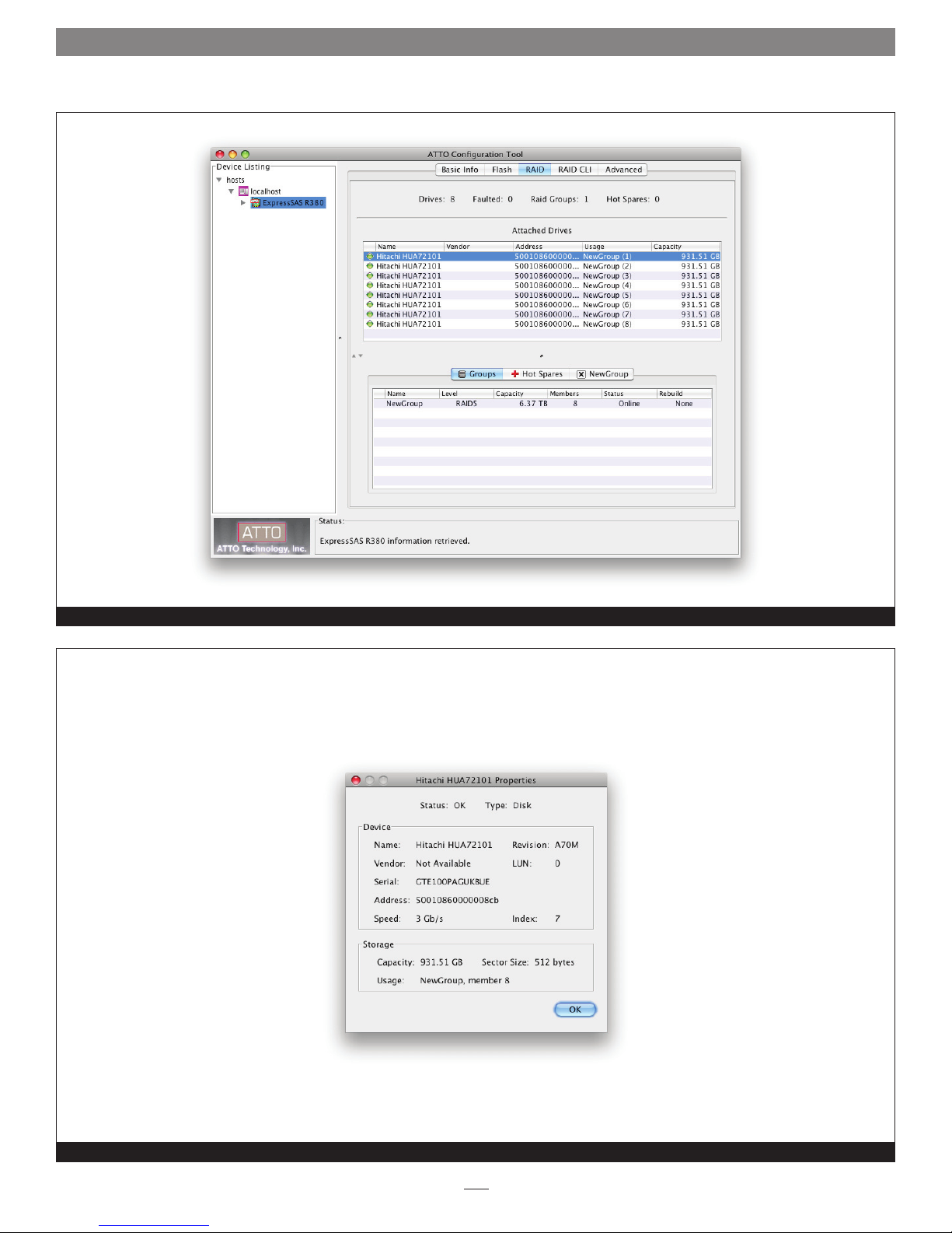
Basic Drive Information
Open the ATTO Configuration Tool and expand the device tree in
the Device Listing pane until ExpressSAS Rxxx appears, and then
click to highlight it. In the Attached Drives pane, information for
all the drives is displayed. See
LED icon: Indicates operational status of the drives. Green =
•
online, red = faulted
• Name: Displays the drive’s model number
Vendor: Not used
•
Address: Displays the SAS address generated by the Sonnet
•
RAID controller
• Usage: Identifies how the drive is being used. If it is part of
a RAID group, the group name and member number are
displayed. If it is a Hot Spare, it is listed as a Hot Spare.
•
Capacity: Displays the drive’s formatted capacity.
Figure 16 on page 19.
Detailed Drive Information
In the Attached Drives pane, double-click a drive name for
detailed information. See
Status: Displays the drive’s operating status. OK is displayed if it
•
is functioning normally. If there is a problem, Faulted or Error is
displayed.
Type: Displays the type of media (disk, tape, etc.)
•
Name: Displays the drive’s model number
•
Vendor: Not used; always displays Not Available
•
Figure 17 on page 19.
•
Index: Displays the RAID group index number
Capacity: Displays the drive’s formatted capacity
•
Usage: Identifies how the drive is being used. If it is part of
•
a RAID group, the group name and member number are
displayed. If it is a Hot Spare, it is listed as a Hot Spare.
•
Sector Size: Displays the drive’s sector size
RAID Group Information
In the bottom pane, click the Groups tab to display RAID groups.
See
Figure 16 on page 19.
Name: Displays the name of the RAID group
•
Level: Indicates the RAID level formatting for the RAID group
•
Capacity: Indicates the formatted, configured capacity of the
•
RAID group
• Members: Identifies the number of drives comprising the RAID
group
Status: Displays the operating status for the RAID group.
•
ONLINE indicates that there are no faulted drives and the
group is fully operational; DEGRADED indicates that one drive
in the group has failed and it should be replaced as soon as
possible; OFFLINE indicates more than one drive in the group
has failed or is missing and the RAID group is non-operational;
REBUILD indicates that a drive in the group is rebuilding, and
the group is still operational, but running in degraded mode.
•
Rebuild: Specifies the general condition of the RAID group.
None indicates no rebuild is taking place, nor is it necessary;
Rebuilding indicates that the RAID group is degraded, and is in
the process of rebuilding; Paused indicates that a rebuild was
interrupted and needs to be restarted to finish.
Individual Drive Identification
You may identify individual drives in the Fusion drive enclosure
using the ATTO Configuration Tool to turn on LEDs in the
enclosure.
Serial: Displays the drive’s serial number
•
Address: Displays the SAS address generated by the Sonnet
•
RAID controller
• Speed: Displays the drive’s interface speed (1.5 or 3 Gb/s)
Revision: Displays the drive’s firmware revision
•
LUN: Displays the logical unit number, which is the number
•
assigned to drive’s RAID group
1. Launch the ATTO Configuration Tool application.
2. Expand the device tree to show the ExpressSAS Rxxx, and
then click the RAID tab. Drive status for all drives connected
to the Sonnet RAID controller will be displayed.
3. Click on the specific drive you want to identify in the
Attached Drives list.
17
Page 22

1.3 Drive and RAID Group Monitoring
Individual Drive Identification (continued)
4. Select RAID Management > Locate > Drive from the
application menu. If the drive does not support this method
of identification, a message will appear in the bottom pane;
go to the next step. Otherwise, look at the Fusion enclosure;
the drive activity LED for the specific drive will be lit. After
one minute, the LED will turn off.
5. Double-click a drive in the top pane to display detailed
information, and note the index number for the drive. Close
the detailed drive information window.
6. Click the RAID CLI tab, and then type “Blockdevidentify x”,
where
x is the index number. Look at the Fusion enclosure;
the drive activity LED for the specific drive will be lit.
Note: Type “Blockdevidstop” to turn off the LED.
S.M.A.R.T. Data Monitoring
Self-Monitoring, Analysis and Reporting Technology, or
S.M.A.R.T., is a monitoring system for SATA drives to detect and
report on various indicators of drive health. The S.M.A.R.T. (SelfMonitoring, Analysis and Reporting Technology) monitoring
feature monitors and reports the status of SATA drive health
using certain parameters recorded by the drives. Notification is
sent when the values exceed certain pre-determined values.
Use the ATTO Configuration Tool to view the files that record
changes to an individual drive’s S.M.A.R.T. parameters. The files
are permanent and can be viewed independently whether you
have enabled monitoring or not.
S.M.A.R.T. Monitoring Enabling and Disabling
You may enable or disable the monitoring feature at any time.
Monitoring is disabled by default; if you want to use the feature,
you must enable it.
1. Launch the ATTO Configuration Tool application.
2. Expand the device tree to show the ExpressSAS Rxxx, and
then click the RAID tab.
3. Select RAID Management > Monitor S.M.A.R.T. from the
application menu to enable (indicated with a check mark) or
disable monitoring.
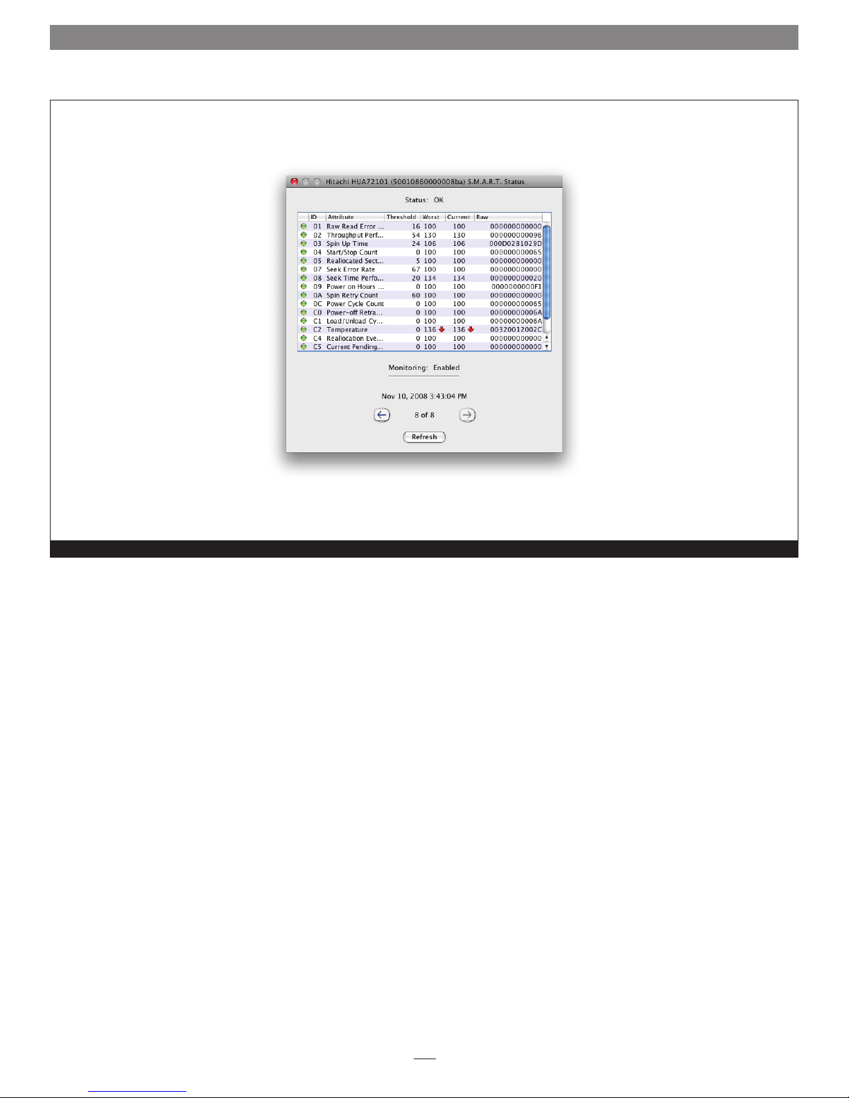
S.M.A.R.T. Status Checking
The ATTO Configuration Tool interface displays the latest
S.M.A.R.T. status record for a selected drive. All attributes reported
by the drive are listed with each attribute’s
Current and Raw value; the threshold value is the value at which
notification of a problem is generated by the software.
If there has been a change from a previous S.M.A.R.T. status
record, an arrow indicates the change direction, either higher or
lower. See
Figure 18 on page 20.
Threshold, Worst,
The S.M.A.R.T. status display also contains information such as
the date and time the S.M.A.R.T. status was recorded, the total
number of records for this drive, and the current monitoring
status (enabled or disabled).
You may move to previous or subsequent records, query the drive
or refresh the view using controls on the interface. Control-click
(or right-click) a single drive in the Attached Drives panel, and
select S.M.A.R.T. Status from the sub-menu to view the record.
• Use the left arrow or right arrow control to move between
S.M.A.R.T. status records.
• Use the Refresh button to query the drive for the latest values.
If any values are different from the most recent record, a new
record is created and displayed.
S.M.A.R.T. Attribute Filtering
Each of the S.M.A.R.T. status attributes is assigned one or more
classification types:
• performance
• error rate
• event count
• critical
The S.M.A.R.T. Status dialog box can be filtered to display any
combination of these types. The default view is to display all types.
1. Open the S.M.A.R.T. Status box, and then control-click (or
2. Each classification type that is visible has a check mark.
right-click) in the table area where the attribute values are
displayed.
Select any classification type to change the check mark.
S.M.A.R.T. Notifications
When S.M.A.R.T. monitoring is enabled, status is collected from
each SATA drive at 60 minute intervals. If the data is different
than the previous status, a S.M.A.R.T. status record is added to the
S.M.A.R.T. status file for that drive. A notification of the S.M.A.R.T.
status difference is generated based upon the current settings in
the Notifications panel. Refer to Notifications on page 21.
The notification level of S.M.A.R.T. status is determined as
follows:
INFO: None of the status values was below the threshold value.
•
WARNING: One or more of the status values was below a
•
threshold value but none was classified as critical.
• CRITICAL: One or more of the status values was below a
threshold value and one was classified critical.
18
Page 23
1.3 Drive and RAID Group Monitoring
Drive information displayed with RAID tab selected
Detailed drive information
Figure 16
Figure 17
19
Page 24
1.3 Drive and RAID Group Monitoring
S.M.A.R.T. status displayed for a specific drive
Figure 18
20
Page 25

1.4 Notifications
The ATTO Configuration Tool provides a way to issue notifications via
audible or visual alerts when a RAID event occurs.
RAID events are divided into three categories:
• Critical events are ones in which a serious problem has
occurred and the administrator of the RAID group should
perform corrective action.
• Warning events are less serious but still warrant recording and
notification at some level.
• Information alerts provide supportive information about
warnings or critical events.
Drop-down boxes on the Notifications pane allow you to choose
the type of event which prompts an alert. See Figure 19 on
page 22.
• Critical: only Critical events are reported
• Warning: all Warnings and Critical events are reported
• All: all Critical, Warning and Information events are reported
Logging
Logging notification records the type of event as text in a log file
you specify. Select the location, name and size of the file.
• An integer value is added to the log name. When the log
file reaches its size limitation, a new file is generated with a
sequential integer value added to the log name. When the
second log file reaches its size limitation, logging overwrites
the first log file. The two log files are automatically rotated.
E-Mail Alert
E-mail notification sends a message to the designated E-mail
addresses when the event level from the drop down box is
reached.
• You may specify several notification addresses on each line in
the E-mail section of the Notifications pane, each separated by
commas, for any event level.
• You must complete the IP address or name of the server and
sender.
• You may specify a user name and password for the mail server
if one is required.
• None: no event is reported. The None level is useful in E-mail
notification because you can set up E-mail addresses to which
alerts might be sent at some future time.
You may choose any combination of notifications on the
Notification pane as needed. The notifications are specified at
the host system level and apply to all Sonnet RAID controllers
installed in the host system.
Basic Alerts
You can select an audible alert, a visual alert, or both for a
particular category of events. Select a notification level using the
drop-down box next to the Audible and Visual labels on the
Notifications screen.
Audible alert uses the computer’s speaker to sound an alarm for
5 seconds.
Visual alert uses a system modal pop-up to display a message.
You must close the pop-up using the pop-up’s button.
Support Note: The visual alert option is not available on
systems running Linux, nor on systems running Mac OS X
and using version 3.1.0 software.
• A critical event E-mail notification is sent after a 10-second
delay to allow several related events to be reported in the same
message. All other notification E-mails are sent at 15-minute
intervals.
21
Page 26

1.4 Notifications
Configuration Tool Notifications screen
Figure 19
22
Page 27

1.5 Diagnose and Replace a Faulted Drive
A drive error may occur that will cause a RAID group to become
degraded. This section will help you to identify and replace the bad
drive.
When an error occurs that requires a drive to be replaced, the
ATTO Configuration Tool will issue visual, audible, and E-mail
notifications (only when configured to do so).
Support Note: The Sonnet RAID controller is unable to
automatically turn on fault lights in the drive enclosure,
so the ATTO Configuration Tool must be used to activate the
LED for the faulted drive.
Faulted Drive Identification
After a drive failure notification has appeared,
1. Launch the ATTO Configuration Tool application.
2. Expand the device tree to show the ExpressSAS Rxxx, and
then click the RAID tab. Drive status for all drives connected
to the Sonnet RAID controller will be displayed. The faulted
or degraded drive will have a red LED icon next to it.
Support Note: If you have configured your setup to
include a Hot Spare drive, the ATTO Configuration Tool
will automatically start rebuilding the RAID group using the Hot
Spare drive.
Faulted Drive Replacement
Once you have identified the faulted drive, you must replace it
and rebuild the affected RAID group.
1. Swap out the faulted drive.
2. Launch the ATTO Configuration Tool application.
3. Expand the device tree to show the ExpressSAS Rxxx, and
then click to highlight the degraded RAID group.
4. Select RAID Management > Rebuild from the application
menu; a tab for the RAID group will open, and you will
be prompted to drag a free drive on top of the one being
replaced. See
5. After starting the rebuild, you may use the RAID group, but
its performance will be reduced until the rebuild is complete.
Support Note: A RAID group rebuild may take up to
eight hours to complete, depending on the operating
system, drive capacities, and RAID configuration.
Figure 19 on page 24.
3. Click on the faulted or degraded drive you want to identify
in the Attached Drives list.
4. Select RAID Management > Locate > Drive from the
application menu. If the drive does not support this method
of identification, a message will appear in the bottom pane;
go to the next step. Otherwise, look at the Fusion enclosure;
the drive activity LED for the specific drive will be lit. After
one minute, the LED will turn off.
5. Double-click the faulted or degraded drive in the top pane to
display detailed information, and note the index number for
the drive. Close the detailed drive information window.
6. Click the RAID CLI tab, and then type “Blockdevidentify x”,
where
x is the index number. Look at the Fusion enclosure;
the drive activity LED for the specific drive will be lit.
Note: Type “Blockdevidstop” to turn off the LED.
23
Page 28

1.5 Diagnosing and Replacing a Faulted Drive
RAID group rebuild
Figure 20
24
Page 29

1.6 Configuration Tool Troubleshooting
You may see an error message informing you about an unexpected event
or incorrect information discovered by the application. Using the help text
presented with the error message, correct the issue before proceeding.
Warnings and error messages are displayed in the
Status pane.
Messages from NVRAM Tab Actions
• An error occurred loading NVRAM data.
The first time a channel is highlighted, the Configuration Tool
attempts to read NVRAM from the card. This message usually
indicates that the Configuration Tool could not communicate
with the driver, probably because the application does not
support the driver version in use.
• Warning: NVRAM could not be read, defaults returned.
NVRAM is corrupt and the driver returns to the default
configuration. The defaults are presented via the graphical user
interface. These defaults may be modified but the defaults or
modifications must be committed (saved) in order to correct
NVRAM.
•
An error occurred updating the NVRAM.
The driver cannot load the new settings on the card; no changes
are made to the card.
•
Feature bounds checking.
When the
is validated before being sent to the card. If any one of these
features is deemed inappropriate based on the implemented
checks, further NVRAM feature validation checks are stopped
and the message is displayed, for example:
is greater than the maximum allowable value of 255. No
NVRAM configuration changes have been made to your card.
The exact message varies based on the first field with an out-ofrange value.
Commit button is clicked, each NVRAM feature
Execution Throttle
Messages from Flash Tab Actions
• This is not a flash file, or it is corrupt.
The ATTO-created flash file is corrupt or the Configuration
Tool does not recognize the file as a flash file. Only ATTOcreated flash files may be selected using the flash file dialog box.
• This HBA is not compatible with the selected flash file.
ATTO flash files are created based on the type of card flashed.
Only certain ATTO flash files are compatible with the Sonnet
RAID controller. When a flash file is selected, it is inspected for
compatibility.
•
A valid file was not selected.
You clicked the Cancel button on the flash file selection dialog.
• An error occurred reading from the flash file, the file may be
corrupt.
You selected a compatible flash file but the contents are corrupt.
• An error occurred updating the flash.
You tried to flash a card when the firmware was not able to
accept a flash.
•
The card has been prepared for firmware updating, but the
machine must be rebooted for the changes to take effect.
You need to repeat this process after rebooting to actually
update the firmware.
Some firmware upgrades need to prepare the existing firmware
in order to successfully update the controller. Rebooting allows
the changes made during the preparation process to take effect,
and the same file should be flashed again.
25
Page 30

26
Page 31

2.0 Windows Only - ATTO Disk Benchmark
The ATTO Utilities for Windows are installed from the CD that was
included with your Sonnet RAID controller. Only one utility, Disk
Benchmark, may be used with your Sonnet RAID storage system.
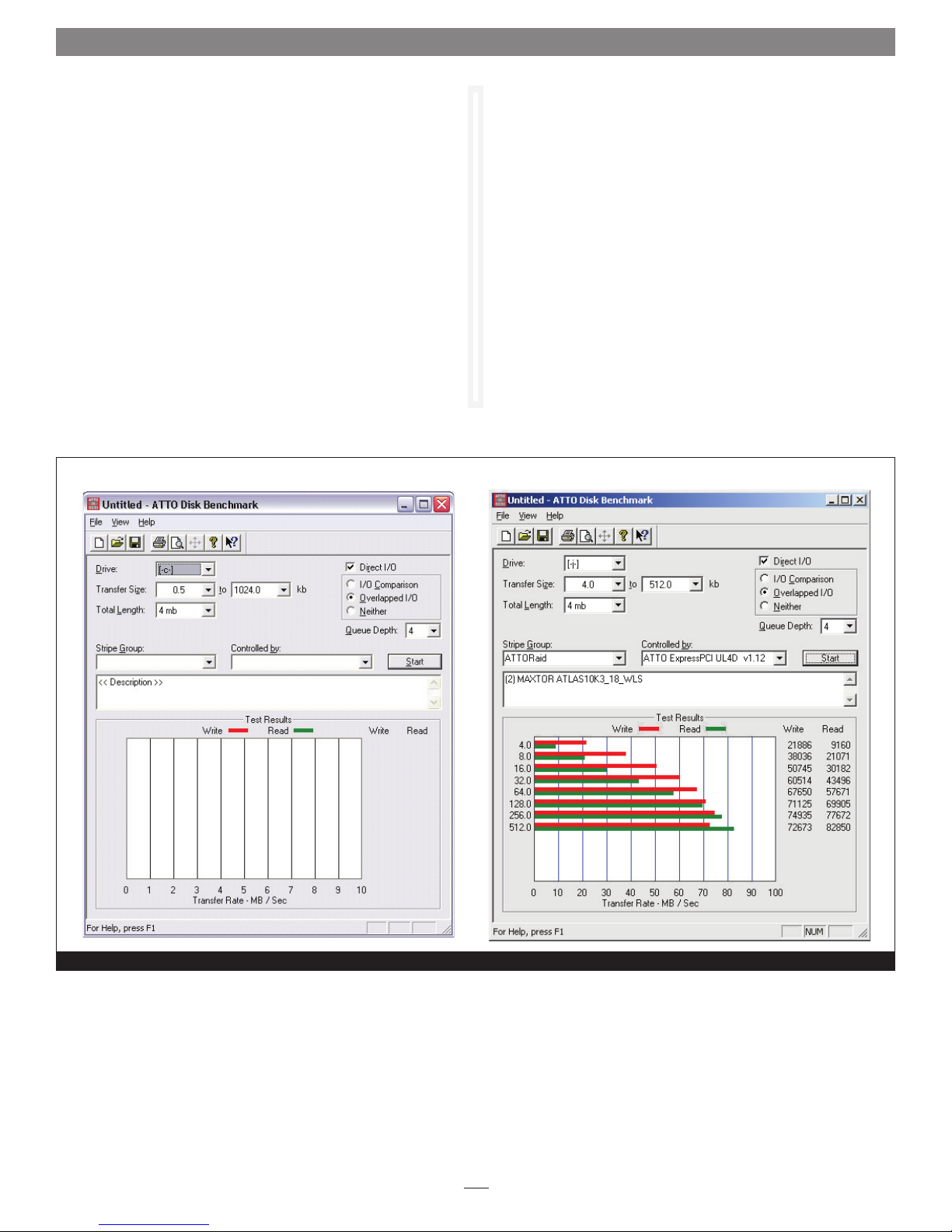
Disk Benchmark measures peak and sustained throughput for
disk reads and writes. See Figure 21 on page 28. You may locate
the Disk Benchmark application in the ATTO HBA Utilities folder
within your system’s Applications folder.
1. Launch the application.
2. Select the drive letter for the disk to benchmark.
3. Select the transfer sizes to test.
4. Select the I/O option.
5. Click the Start button.
6. Wait for benchmark to run through the desired transfer sizes.
7. The Test Results Display at the bottom of the window is
updated as the test progresses. The y-axis of the graph
represents the transfer sizes in the selected range. The x-axis
represents the transfer speeds in MB/sec. I/O speeds in KB/sec.
for each transfer size are displayed textually to the right of the
graph.
Support Note: Additional information on using Disk
Benchmark is available by accessing the Help menu in the
application.
Benchmark Fields
The benchmark fields include:
Drive: Select the logical drive to benchmark. A test can be
•
performed on any system drive.
• Transfer Size: Select the range of transfer sizes used for reading
and writing data to the test drive. Transfer speeds are displayed
for each size in the range. If the first size is greater than the
second size, the test is not performed for any transfer size.
•
Total Length: Select the total size of the data file to be created
on the test drive. This file is deleted when testing completes.
• Direct I/O: If this option is checked, file I/O on the test drive
is performed with no system buffering or caching. Combine
this option with
performance
Overlapped I/O for maximum asynchronous
Radio Button Group
• Overlapped I/O performs queued I/O. Upon selection, the
Queue Depth option displays to select the maximum number of
read or write commands that may be executed simultaneously.
8. Click the Stop button to stop the test. When the test
completes, the results can be saved or printed.
If errors were detected, a dialog box displays the errors in a table
with the following four columns and a button:
• Benchmark Transfer Size: transfer size at which the error
occurred
• Buffer Index: index into the data block at which the error
occurred
• Actual Value: the value read from the file
Expected Value: the value written to the file
•
Log to File: Logs the error table to a *.log file and closes the
•
dialog. The file is given the same name as the test file and saved
in the same directory. If the test was not previously saved, errors
are logged to the generic file Bench32Error.log in the root of
the test drive. If the log file already exists, the new errors are
appended to the previously recorded errors. This is the only
way to save detected errors. They are not saved in the test
document file.
If the I/O comparison option was selected and errors were not
detected, the message “No errors detected” is displayed.
• I/O Comparison compares the data read from the test file to
the data written on a per block basis. You can select the data
pattern for comparison from the
Run Continuously runs the test continuously for a specified
•
number of minutes. The test stops before the specified time if
any errors are detected.
•
Neither: Select if you do not want to perform overlapped I/O or
I/O comparisons.
The following fields do not affect the benchmark but are
informational, providing documentation of the test environment.
• Stripe Group: If the test drive is a stripe group, select its name
from the list box. The names and quantities of drives in the
stripe group are printed to the Description box. Select Clear to
clear the contents of the Description box.
•
Controlled by displays all Sonnet RAID controllers in the
system.
• Description: Enter additional information about the test that
can be saved or printed. Be sure to enter additional information
after making a selection from the Stripe Group dropdown box,
as this erases the current description.
Test Pattern drop-down box.
27
Page 32
2.0 Windows Only - ATTO Disk Benchmark
Multiple Benchmark Testing
Disk Benchmark supports four command line parameters for
uninterrupted testing:
• testfile opens and executes the test named
extension .
textfile opens the text file named textfile. This file contains a
•
list of test file names that have an extension of
in this list is opened and executed in order. Stopping one test in
the list prevents further tests from being executed. Error logging
is the same as the command line parameter testfile, but all
errors generated from all tests in the list are logged to one file:
textfile.log.
Disk Benchmark screens before and after a test has been run
bmk.
testfile with the
.bmk. Each test
• /p testfile: Same as
default system printer instead of being executed.
• /p textfile: Same as textfile, only the tests in the list are printed
to the default system printer instead of being executed.
testfile, only the test is printed to the
Figure 21
28
Page 33

2.1 ATTO Disk Benchmark Troubleshooting
The following suggestions may help if you encounter problems with
Disk Benchmark.
• Use Windows Device Manager to check and verify that all
drives are visible to the operating system.
• If drives are not listed, check the connections between the drive
enclosure and the RAID controller card, and verify that all
drives are fully seated in their bays.
• Make sure that the enclosure is powered up and has completed
its self check before booting your computer.
• Reboot your system any time you make changes to a RAID
group (after the RAID group has been rebuilt).
• As a last resort, you may use the ATTO Boot Configuration
Utility to low level format a troublesome device. However, this
erases all information on the disk.
• Have you partitioned your drive, and then activated that
partition?
• Did you format the drives for use with your operating system?
If problems persist, contact Sonnet customer service.
29
Page 34

30
Page 35
Appendix A - CLI ASCII-Based Interface
The command line interface (CLI) uses ASCII commands typed in the
CLI window.
WARNING: Do not use CLI unless you are directed to by
a Sonnet technician, as changing parameters may cause
loss of data and/or disruption to performance and reliability
of the Sonnet RAID controller. The ATTO Configuration Tool
interface is the preferred method to operate and manage the
Sonnet RAID controller.
The command line interface (CLI) uses a set of ASCII-based
commands to control configuration and diagnostic tasks. See
Figure 6 on page 5.
• CLI commands are context sensitive and generally follow a
standard format
Get|Set] Command [Parameter1|Parameter2]
followed by the
• CLI commands are case insensitive: you may type all upper
or all lower case, or a mixture. Upper and lower case in this
manual and the
• Commands generally have three types of operation: get, set
and immediate.
return or enter key
help screen are for clarification only.
• The get form returns the value of a parameter or setting and is
an informational command.
• Responses to get commands are followed by Ready.
• The set form is an action that changes the value of a parameter
or configuration setting. It may require a SaveConfiguration
command and a restart of the system before it is implemented.
The restart can be accomplished using a separate
FirmwareRestart command. A number of set commands may
be issued before the
• Responses to
or
Ready. *. The asterisk indicates you must use a
SaveConfiguration command.
set commands are either an error message
SaveConfiguration command to finalize the set command.
• Set commands which do not require a
SaveConfiguration
command, defined as immediate commands, are immediately
executed.
Support Note: Using certain CLI commands during
normal operation can cause a performance drop. Once
command actions are complete, per formance should return to
normal levels.
Figure A-1 Symbols, typefaces, and abbreviations used to indicate functions and elements of the command line interface used in this manual.
Symbol
Indicates
[ ] Required entry
< > Optional entry
| pick one of
- a range (6 – 9 = 6, 7, 8, 9)
BlockDevID index designation of a block device not assigned to any other RAID group; the index of a block device provided by the
BlockDevScan CLI command. 0<=n<=63
DevIndex index designation of the RAID member
GroupName the name of the RAID group to which the block device is assigned, or blank if the drive is available
MemberIndex index designation of a RAID group member
PartID index designation of a partition as found in the PartitionDisplay command
tid Target ID 0<=n<=255
i
Page 36

Appendix A - CLI ASCII-Based Interface
CLI Error Messages
The following error messages may be returned by the Command
line Interface
ERROR Invalid Command. Type 'Help' for command
list.
ERROR Command Not Processed
ERROR Wrong/Missing Parameters
ERROR Invalid Hot Spare Serial Number
ERROR Invalid RAID GroupName
ERROR Invalid RAID Group State
ERROR Insufficient number of RAID Group members
ERROR RAID Group does not exist
ERROR No RAID Groups found
ERROR Invalid RAID Type
ERROR RAID Group is already unmapped
ERROR Invalid Block Device Index
ERROR Cannot perform operation. RAID Group has
mapped Partitions
ERROR Cannot perform operation. RAID Group has
Outstanding Commands
ERROR Block Device at specified index no longer
available
ERROR Insufficient RAID Group members for RAID
type
ERROR Incorrect number of RAID Group members for
QuickVideo configuration
ERROR Invalid Virtual Drive ID
ERROR Specified capacity is invalid
ERROR Too many Indices specified.
ERROR Only one add storage operation is permitted
at any given time.
ERROR No free block devices
ERROR Cannot benchmark a drive that is being
initialized
ERROR Invalid RAID MemberIndex
ERROR Invalid RAID Member State
ERROR Missing RAID Member
ERROR Invalid RAID Member Capacity
ERROR Invalid Partition Index
ERROR Maximum number of RAID Groups exceeded
ERROR Maximum number of Partitions exceeded
ERROR Invalid number of Partitions
ERROR Maximum number of RAID Members exceeded
ERROR Maximum stripe width
ERROR Invalid number of Partitions specified
ERROR Invalid Span Depth specified
ERROR Cannot perform operation on mapped Partition
ERROR Specified drive is not being monitored
ii
Page 37
Appendix A - CLI ASCII-Based Interface
CLI Summary
The following chart summarizes the Command Line Interface
commands, their defaults, and an example of how to enter the
commands. Please note that commands which have no default
values have a blank entry in that column of the table.
WARNING: Do not use the CLI unless you are directed
to by a Sonnet technician, as changing parameters may
cause loss of data and/or disruption to performance and
reliability of the Fusion storage system.
Command Default Example
AutoMap
AutoMapOnBoot disabled set automaponboot enabled
AutoResume rebuild, initialize = all enabled;
erase = all disabled
BlockDevClean blockdevclean 30
BlockDevIdentify blockdevidentify 30
BlockDevIDStop blockdevidstop
BlockDevScan blockdevscan
BootDelay 0 set bootdelay 125
ClearEventLog cleareventlog
Date set date 03/03/2009
DefaultInterleave 128 set defaultinterleave 64
DriveHealth disabled setdrivehealth enabled
DriveHealthDisplay drivehealthdisplay all
DriveHealthStatus drivehealthstatus
DeleteAllMaps deleteallmaps
DriveTest drivetest begin
automap
set autoresume erase disabled G1
DriveTestClearList drivetestclearlist all
DriveTestConfig not initiated set drivetestconfig read
DriveTestList get drivetestlist all
DriveTestStatus get driveteststatus
DumpConfiguration dumpconfiguration
DumpEventLog dumpeventlog
EventLog enabled set eventlog disabled
EventLogFilter all all all set eventlogfilter gen info all
Help help eventlog
HSAdd hsadd 3
HSDisplay hsdisplay
HSRemove hsremove 3
iii
Page 38

Appendix A - CLI ASCII-Based Interface
Command Default Example
Info info
IsReserved isreserved
Metrics metrics display all
Partition partition alpha1 6 4 GB
PartitionDisplay partitiondisplay alpha1
PartitionMerge partitionmerge all
PartitionSplit partitionsplit alpha1 22 2
PartitionWriteCache set partitionwritecache enabled
RAIDRebuildPriority same set raidrebuildpriority low
RAIDSpeedWriteLimit 8 set raidspeedwritelimit 15
Reserve reserve
RestoreConfiguration restoreconfiguration default
RGAddStorage rgaddstorage g1 span commit
RGAutoRebuild disabled set rgautorebuild all enabled
RGCancelAddStorage rgcanceladdstorage g1
RGCommit rgcommit all
RGCreate rgcreate g1 raid0
RGDelete rgdelete all
RGDiskWriteCache set rgdiskwritecache rg1 enabled
RGDisplay rgdisplay all
RGErase rgerase g1
RGHaltConversion rghaltconversion g1
RGHaltErase rghalterase g1
RGHaltInitialization rghaltinitialization g1
RGHaltRebuild rghaltrebuild g1
RGHDParameter 0 set rghdparameter rg 16
RGMemberAdd rgmemberadd g1 22
RGMemberRemove rgmemberremove g1 22
RGRebuild rgrebuild g1
RGResumeConversion rgresumeconversion g1
RGResumeErase rgresumeerase g1
RGResumeInitialization rgresumeinitialization g1
RGResumeRebuild rgresumerebuild g1
RGSectorSize 512 setrgsectorsize g1 8192
RGSpanDepth 1 set rgspandepth g1 22
RGSpeedRead all disabled set rgspeedread g1 enabled
iv
Page 39

Appendix A - CLI ASCII-Based Interface
Command Default Example
RGUnmap rgunmap g1
RGWaitTimeout 5 rgwaittimeout 30
RMState set rmstate g1 online
RMStatus rmstatus g1
Route route host 1 raid alpha1 6
RouteDisplay routedisplay 03 124
SASTargets sastargets
SaveConfiguration saveconfiguration
SerialNumber get serialnumber
Time set time 03:32:30
TimeZone EST set timezone pst
VerboseMode enabled set verbosemode disabled
VirtualDriveInfo virtualdriveinfo
WrapEventLog enabled set wrapeventlog disabled
v
Page 40
Appendix A - CLI ASCII-Based Interface
CLI Command Explanations
Command line interface commands are listed alphabetically with
explanations of what they are used for, their defaults and syntax.
WARNING: Using CLI without contacting a Sonnet
technician is not recommended because changing
parameters may cause loss of data and/or disruption to
performance and reliability of the Fusion storage system.
• AutoMap
Maps RAID groups created with the Configuration Tool to the
operating system, where they are then discovered as single
storage devices. It is possible to create a RAID group that
remains hidden from the operating system, and thus not seen
by Disk Utility, the Finder, or other system discovery tools.
AutoMap
AutoMapOnBoot
•
Regulates the automatic detection and mapping of RAID groups
at startup.
Default: disabled
set AutoMapOnBoot [enabled | disabled]
get AutoMapOnBoot
BlockDevIdentify
•
Turns on a drive activity LED on the Fusion drive enclosure for
one minute if it is accessible.
WARNING: The BlockDevIdentify command is intended
for diagnostic purposes only. Executing this command may
adversely impact the performance and throughput of the Fusion
storage system for the time that the LED is illuminated.
BlockDevIdentify <Groupname> [BlockDevID |
MemberIndex]
BlockDevIDStop
•
Turns off the drive activity LED on the Fusion drive enclosure
that was activated with the BlockDevIdentify command.
BlockDevIDStop
BlockDevScan
•
Lists all currently connected physical drives along with any
potential RAID group association. Each block device listed is
assigned a unique index at the time of the scan to identify
drives for other CLI operations.
BlockDevScan
AutoResume
•
Regulates the automatic continue feature for interrupted rebuild
and erase operations at startup. If AutoResume is enabled,
all interrupted rebuild and erase operations are continued at
startup. If no GroupName is specified, all existing RAID groups
are affected.
Default: all disabled
set AutoResume [Rebuild | Erase | Write Pattern
| all] [enabled | disabled] <GroupName>
BlockDevClean
•
Removes any RAID configuration data from the block device
with the specified BlockDevID.
WARNING: All RAID group setup information is lost
when the BlockDevClean command is performed,
therefore all data is lost. Back up your files before performing
this command.
BlockDevClean [BlockDevID]
BootDelay
•
Regulates the delay in seconds which the unit waits after
startup before allowing hosts to detect discovered targets. The
value 0 constitutes no delay.
Default: 0
set BootDelay [0 - 255]
get BootDelay
ClearEventLog
•
Clears the contents of the event log. No new entries are recorded
until ClearEventLog has completed.
ClearEventLog
Date
•
Regulates the current date for this unit. The date range is
01/01/2000 to 12/31/2099.
set Date [MM]/[DD]/[YYYY]
get Date
vi
Page 41

Appendix A - CLI ASCII-Based Interface
• DefaultInterleave
Assigns or retrieves the system-default interleave size for new
RAID groups, where the interleave size is expressed as the
number of 512-byte blocks. If an interleave size is not
explicitly specified when a RAID group is created, then the
DefaultInterleave value is used.
default interleave size may improve performance, it may degrade
performance.
Default: 128
set DefaultInterleave [8KB | 16KB | 32KB | 64KB
| 128KB | 256KB | 512KB | 1024KB | 2048KB ]
get DefaultInterleave
DeleteAllMaps
•
Removes all mapped devices from the map table.
DeleteAllMaps (requires a SaveConfiguration command)
DriveHealth
•
Changes the system’s ability to acquire drive health data from
connected drives. Issuing this command during I/O operations
may adversely affect performance.
Default: disabled
set DriveHealth [enabled | disabled]
get DriveHealth
DriveHealthDisplay
•
Retrieves and displays S.M.A.R.T. (Self-Monitoring, Analysis
and Reporting Technology) data from SATA drives. Issuing
this command during I/O operations may adversely affect
performance.
DriveHealthDisplay [BlockDevID | all]
DriveHealthStatus
•
Displays the status of the currently running drive test but does
not display performance metrics. If a block device ID is not
running or cannot be found, its state will be idle and percent
complete will be 0.
get
DriveHealthStatus <drive [BlockDevID]>
DriveTest
•
Regulates a drive test with the previously specified configuration
(refer to
Drives being tested are not available for RAID configuration or
RAID operations. Only one test can be run at a time.
DriveTest [Begin | Cancel]
DriveTestConfig ) and drive list (refer to DriveTestList).
Note: Although changing the
•
DriveTestClearList
Specifies the drive to be removed from the drive test list. the
drive BlockDevID parameter removes the specified drive from
the list. The all parameter removes all drives from the list.
DriveTestClearList [BlockDevId | all]
DriveTestConfig
•
Configures the next drive test to perform one of the following
operations: The test is not started until the DriveTest Begin
command is given.
init: initialize, destructive, write-only
read: non-destructive, read-only
verify: destructive verify
init-verify: destructive write-read-verify
set DriveTestConfig [init | read | verify |
init-verify]
get DriveTestConfig
DriveTestList
•
Specifies drives to be run in the next drive test including drives
which are not part of a RAID group and not Hot Spares. The all
parameter automatically chooses eligible drives. The test is not
started until the DriveTest Begin command is given.
set DriveTestList [drive [BlockDevID] | all]
get DriveTestList
DriveTestStatus
•
Displays the status of the currently running drive test but
does not display performance metrics. If a block device ID is
not running or cannot be found, its state is idle and percent
complete is 0.
get DriveTestStatus <drive [BlockDevID]>
DumpConfiguration
•
Displays a unit’s configuration to the management interface.
DumpConfiguration
DumpEventLog
•
Dumps the contents of the entire event log to the management
interface. No events are recorded until the command has been
completed.
DumpEventLog
EventLog
•
Regulates event logging. When enabled, records various system
errors to the event log.
Default: enabled
set EventLog [enabled | disabled]
get EventLog
vii
Page 42

Appendix A - CLI ASCII-Based Interface
• EventLogFilter
Filters data from specific unit subsystems and levels when event
logging is enabled. The specific entries supported are platformdependent. For set commands, the final parameter indicates
whether or not events from the specified subsystem and level
are displayed.
Default: all all all
set EventLogFilter [subsys | all] [event level
| all] [all |none]
get EventLogFilter [subsystem] [level]
Help
•
Displays a list of available commands. If command name is
specified, displays detailed command-specific information
Help <command name>
HSAdd
•
Assigns a Block Device to the Hot Spare pool.
HSAdd [BlockDevID]
HSDisplay
•
Lists all devices in the Hot Spare pool.
HSDisplay
HSRemove
•
Removes a Block Device from the Hot Spare pool
HSRemove [BlockDevID]
Info
•
Displays version numbers and other production information for
key components.
Info
IsReserved
•
Displays the reservation status of the current services session or
interface.
IsReserved
Metrics
•
Controls the collection of standard data metrics within a
product based on the command parameters.
Metrics [Start | Stop | Display] [drive
[BlockDevID] | all | running]
•
Partition
Creates a specified partition to the specified capacity in
Gigabytes (GB), Megabytes (MB), or blocks. The specified
capacity must be smaller than the specified partition’s current
capacity. A new partition is created to acquire the remainder
of the original partition’s space.
characteristics and statistics for all the available virtual drives or
any available virtual drive identified by its virtual drive ID.
Partition [GroupName] [PartIndex] [capacity] [GB
| MB | blocks]
PartitionDisplay
•
Lists all the partitions available in the specified RAID group. The
partitions are listed contiguously (as opposed to index order).
PartitionDisplay [GroupName]
PartitionMerge
•
Combines the specified contiguous partitions into one
partition. PartIdx is the index of a partition as found in
PartitionDisplay. All indicates that all partitions in the RAID
group are merged into a single Virtual Disk. The RAID group
must not be in a NEW state. None of the partitions to merge
may be mapped.
PartitionMerge [GroupName] [[[PartIdx] [2-128]] |
All]
PartitionSplit
•
Divides the specified partition into one or more partitions
whose capacities are evenly distributed among the capacity of
the original partition. The partition to split cannot be mapped
and the RAID group must not be in a NEW state.
PartitionSplit [GroupName] [PartIdx] [1-128]
PartitionWriteCache
•
If enabled, allows higher write performance with a small risk
of data loss after a system failure. If disabled, provides a higher
level of data integrity with lower write performance.
set PartitionWriteCache [GroupName] [PartIndex]
[enabled | disabled]
get PartitionWriteCache [GroupName] [PartIndex]
RAIDSpeedWriteLimit
•
Regulates the limit on the coalescing factor. A very low
limit is recommended for multiple initiators; a high limit is
recommended for multiple streams of sequential write I/O.
Default: 8
set RAIDSpeedWriteLimit [0 - 256]
get RAIDSpeedWriteLimit
VirtualDriveInfo displays
viii
Page 43

Appendix A - CLI ASCII-Based Interface
• RAIDRebuildPriority
Sets or displays the RAID rebuild priority. A RAID rebuild
priority set to high gives higher priority to RAID rebuilds
and lower priority to the processing of simultaneous I/O
transactions. A RAID rebuild priority set to low gives lower
priority to the rebuild and a higher priority to I/O transactions.
Set same, the RAID rebuild and processing of I/O transactions
is the same.
Default: same
set RAIDRebuildPriority [high | low | same]
get RAIDRebuildPriority
Reserve
•
Reports the state of CLI reservation for the current CLI session.
If the command reports that Reservations are enabled, then
another CLI session has control of parameter modification on
the unit.
Reserve
RestoreConfiguration
•
Issued with the default option, forces the unit NVRAM settings
to their original defaults. The saved option undoes any changes
made to this session since the last save.
RestoreConfiguration [Default | Saved]
RGAddStorage
•
Adds additional storage to an existing RAID group.
Stripe, or Span specifies the method used to expand the
storage. Optional parameter list
to 10 available block devices, provided by the
command, to be added to the RAID group. If this list is
omitted, the command
Optional parameter
automatically and all user data is erased from each new
member drive. If the parameter is omitted, the command
RGCommit must be entered. RGCancelAddStorage can be
used at any time before the commit command is used to cancel
the process. specifies that the
automatically.
RAID 6, or DVRAID RAID group.
RGAddStorage [GroupName] [Mirror | Stripe |
Span] <BlockDeviceID… <commit>
RGAutoRebuild
•
Regulates whether a RAID group automatically rebuilds.
Default: disabled
set RGAutoRebuild [GroupName | all] [enabled |
disabled]
get set RGAutoRebuild [GroupName | all]
Mirror,
BlockDeviceID specifies up
BlockDevScan
RGMemberAdd must be used.
commit runs the RGCommit command
RGCommit command is run
Note: Mirrors cannot be added to a RAID 4, RAID 5,
•
RGCancelAddStorage
Cancels the
RGCancelAddStorage [GroupName]
RGCommit
•
Stamps a NEW RAID group’s configuration to its member
drives. After this command, a RAID group can be considered
operational and transitions from the NEW state to the Online,
Degraded, or Offline state depending on the health of the
selected member drives.
RAID group’s configuration to its member drives as storage is
being added. If the init option is specified, previous user
configuration information is erased from each member drive.
RGCommit [GroupName | all] [init]
RGCreate
•
Creates a new empty RAID group. The optional value after the
RAID group type parameter represents the desired interleave
for the RAID group, where the interleave size is expressed as
the number of 512-byte blocks. If this value is not provided
then the system-default interleave size is used (refer to
DefaultInterleave ).
RGCreate [GroupName] [RAID [ 0 | 1 | 10 | 4 | 5
| 6 ] | JBOD] <8KB | 16KB | 32KB | 64KB | 128KB
| 256KB | 512KB | 1024KB | 2048KB>
RGDelete
•
Deletes all RAID groups or the specified RAID group.
RGDelete [GroupName | all]
• RGDiskWriteCache
If enabled, produces higher write performance with a small risk
of data loss after a system failure. If disabled, drives are updated
at the expense of some write performance.
set RGDiskWriteCache [GroupName | all] [enabled
| disabled]
get RGDiskWriteCache [GroupName | all]
RGDisplay
•
Displays status information for a single RAID group, or if
used, all available RAID groups.
RGDisplay [GroupName | all ]
RGErase
•
Erases the data from the specified existing RAID group.
All data is lost if you use the RGErase command.
RGErase [GroupName]
RGAddStorage command.
RGCommit also stamps an existing
All is
Note:
ix
Page 44

Appendix A - CLI ASCII-Based Interface
• RGHaltConversion
Stops the conversion on the specified existing RAID group.
RGHaltConversion [GroupName]
RGHaltErase
•
Stops the erase on the specified existing RAID group.
RGHaltErase [GroupName]
RGHaltInitialization
•
Stops the initialization process on the specified existing RAID
group.
RGHaltErase [GroupName]
RGHaltRebuild
•
Stops the rebuild(s) on the specified existing RAID group.
MemberIndex specifies the RAID member whose rebuild is
stopped. If no
RAID group are stopped.
RGHaltRebuild [GroupName] <MemberIndex>
RGHDParameter
•
Shows or sets the HD value for all RAID groups.
set RGHDParameter [GroupName | all] [0–6]
get RGHDParameter [GroupName | all]
RGMemberAdd
•
Adds up to 10 available block devices to a new RAID group (the
RAID group cannot have been saved using the
command). If all is specified, then all unused blocks will be
added to the RAID group until the maximum number of
RAID group members has been met. The command resets the
number of RAID group partitions to 1
RGMemberAdd [GroupName| all] [BlockDevID]
RGMemberRemove
•
Removes a RAID member from a new RAID group (the
RAID group cannot have been saved using the
command). Resets the number of partitions to 1.
RGMemberRemove [GroupName] [BlockDevID]
RGRebuild
•
Rebuilds the specified existing RAID group. If no member is
specified, all degraded members are rebuilt. Optional parameter
BlockDevID allows an available block device to be substituted
for the RAID Member currently assigned to the member index.
If a RAID group has been configured as RAID 6, two RAID
group members can be rebuilt at once
RGRebuild [GroupName] <<MemberIndex>
<BlockDevID> <and MemberIndex2 <BlockDevID2>>>>
MemberIndex is specified, all rebuilds on that
RGCommit
RGCommit
•
RGResumeConversion
Continues the stopped conversion on the specified existing
RAID group.
RGResumeConversion [GroupName]
RGResumeErase
•
Continues the erase on the specified existing RAID group.
RGResumeErase [GroupName]
• RGResumeInitialization
Continues the initialization on the specified existing RAID
group.
RGResumeInitialization [GroupName]
• RGResumeRebuild
Continues the rebuild(s) on the specified existing RAID
group. If no
on that RAID group are continued. For RAID 6 groups, if a
MemberIndex is specified, all halted RAID members on the
span with that MemberIndex resume as well.
RGResumeRebuild [GroupName] <MemberIndex>
RGSpanDepth
•
Regulates the span depth on the specified existing RAID group.
The RAID group must be RAID Level 0, RAID Level 1, RAID
Level 5, or RAID Level 10.
Default: 1
set RGSpanDepth [GroupName] [SpanDepth [1-32]]
get RGSpanDepth [GroupName]
RGSpeedRead
•
Performs look-ahead during reads from RAID group member
disks for all or the specified RAID group.
Default: disabled
set RGSpeedRead [GroupName | all] [enabled |
disabled]
get RGSpeedRead [GroupName | all]
RGUnmap
•
Removes all mapped partitions for a RAID group from the
routing table. The partitions themselves are unaffected but they
are inaccessible to initiators.
RGUnmap [GroupName | all]
MemberIndex is specified, all stopped rebuilds
x
Page 45

Appendix A - CLI ASCII-Based Interface
• RGWaitTimeout
Regulates the maximum time in seconds that the system waits
to discover previously configured RAID groups attached to the
controller.
Default: 5
set RGWaitTimeout [1-300]
get RGWaitTimeout
RMState
•
Regulates the state of the specified existing RAID group
member(s). The RAID group may not be in the new state. If
no
specified RAID group is set.
not changed. Rebuilds on these members must first be stopped.
set RMState [GroupName] <MemberIndex> [Online |
Degraded | Unavailable | Faulted]
RMStatus
•
Displays the status of all RAID group members within the
specified RAID group or a specific RAID member within the
specified RAID group.
RMStatus [GroupName] <MemberIndex>
Route
•
Assigns a RAID partition to a target ID on the host system. If
a map with the specified target ID already exists, the map is
overwritten. Use
Route [host] [TID] [RAID] [GroupName]
[PartIndex]] | SAS {SASIndex]] | Delete]
RouteDisplay
•
Displays a list of host protocol address to target destination
device mappings.
RouteDisplay [host] <tid>
SASTargets
•
Lists the physical devices that are connected to all SAS ports.
SASTargets
SaveConfiguration
•
Issued with the
configuration changes. The
without restarting.
restart.
SaveConfiguration
MemberIndex is specified, the status of all members of the
Note: Members undergoing rebuild are
delete with a target ID to remove the map.
restart option, cycles unit power after saving
norestart option saves changes
Note: Certain modifications require a system
• SerialNumber
Reports the unique serial number for the Sonnet RAID controller
using a 13-character field. The first seven alphanumeric
characters represent the product name; the last six digits are the
unit’s unique number.
get SerialNumber
Time
•
Controls or displays the current time as clocked by the unit in
24 hour format.
set Time [HH: MM: SS]
get Time
TimeZone
•
Controls or displays the time zone or an offset from GMT for
the unit.
Default: EST
set TimeZone [[EST | CST | MST | PST] | [+/-HH:
MM]]
get TimeZone
VerboseMode
•
Controls the level of detail in CLI
response output.
Default: enabled
set VerboseMode [enabled | disabled]
get VerboseMode
VirtualDriveInfo
•
Displays characteristics and statistics for all the available virtual
drives or any available virtual drive identified by its virtual
drive ID.
VirtualDriveInfo <Virtual Drive ID>
WrapEventLog
•
When enabled, the unit logs up to 2,048 event entries before
wrapping (overwriting the first entries). If disabled, the unit
stops logging event entries when the buffer is full.
Default: enabled
set WrapEventLog [enabled | disabled]
get WrapEventLog
Help output and command
xi
Page 46

Appendix B - Quick Drive Format Instructions
If your Sonnet Fusion RAID storage system shipped with pre-installed
hard disk drives, the following information will assist you to reformat
the drives per your needs.
In Fusion RAID systems shipped from Sonnet with hard disk
drives installed, the drives are formatted Mac OS Extended
(Journaled), and configured as a single RAID 5 RAID group.
If you need to change the configuration, use the ATTO
Configuration Tool and the operating system software tools to
reformat and reconfigure the drives.
Mac OS Users’ Instructions
1. Follow all the steps in the included documentation to install
the software and the Sonnet RAID controller, and to set up
and connect the Fusion RAID drive enclosure.
2. Start your computer, and then turn on the Fusion drive
enclosure; the RAID volume should appear on the desktop.
3. Drag the volume to the trash (changes to an eject icon) to
eject it.
4. Launch the ATTO Configuration Tool.
5. Select RAID Management > Delete Group from the
application menu.
14. Depending on how you configured the RAID groups, the
volumes may already be mounted and present on the desktop.
If you created a DVRAID, RAID Level 4, or RAID Level 5
group, configuration will take much longer. You may check
on the process by double-clicking the RAID group name in
the lower pane of the
ATTO Configuration Tool window.
Windows Users’ Instructions
1. Follow all the steps in the included documentation to install
the software and the Sonnet RAID controller, and to set up
and connect the Fusion RAID enclosure.
2. Start your computer, and then turn on the Fusion drive
enclosure.
3. Launch the ATTO Configuration Tool.
4. Expand the device tree in the Device Listing section on the
left side of the window until ExpressSAS Rxxx is displayed,
and then click ExpressSAS Rxxx.
5. Click the RAID tab.
6. In the Groups pane, you will see the RAID group that
Sonnet created (not usable in a Windows system); click the
group.
6. When the Delete Confirmation window appears, click Yes.
7. Set up new RAID groups following the instructions on pages 9
and 10 of this manual.
WARNING: After selecting the DVRAID, R AID Level 4, or
RAID Level 5 option, configuration of a set of eight 1TB
drives can take up to 4 hours (or up to 2 hours with 500GB
drives).
8. Depending on how you configure your setup, a Disk
Insertion window will appear at some point stating that there
is an unreadable volume; click Initialize, and then Disk
Utility will open.
9. In the Disk Utility window, each RAID group you created
using the ATTO Configuration Tool will appear as a single
volume. Select the volume, and then click the Erase tab at the
top of the window.
10. Click Erase; a window will appear asking you to approve
your choice.
11. Click Erase.
12. Repeat steps 7–11 for each remaining unformatted RAID
group.
13. Close Disk Utility.
7. Select RAID Management > Delete Group from the
application menu.
8. When the Delete Confirmation window appears, click Yes.
9. Set up new RAID groups following the instructions on pages 9
and 10.
WARNING: After selecting the DVRAID, R AID Level 4, or
RAID Level 5 option, configuration of a set of eight 1TB
drives can take up to 4 hours (or up to 2 hours with 500GB
drives).
10. Select Computer Management From the Windows Start
menu. If Computer Management is not available in the Start
Menu, select Start > Control Panel > Administrative Tools.
In the
Administrative Tools window, double-click Computer
Management.
11. In the Computer Management window, click Storage on the
left, and then double-click Disk Management.
12. When the Initialize Disk window appears, click OK.
13. In the Disk Management window, each RAID group you
created will appear (listed as “unallocated”) as a single volume.
Right-click where the word “unallocated” appears, and then
select New Simple Volume.
xii
Page 47

Appendix B - Quick Drive Format Instructions
Windows Users’ Instructions (continued)
14. When the Welcome to the New Simple Volume Wizard window
appears, click next to start the process.
15. Follow the remaining steps to complete the process.
Note: If you do not select the quick format option, this process will take
much longer to complete.
16. Repeat steps 13–15 for each remaining “unallocated” disk.
17. Depending on how you configured the RAID groups,
the volumes may already be available to use. If you
created a DVRAID, RAID Level 4, or RAID Level 5 group,
configuration will take much longer. You may check on
the process by double-clicking the RAID group name in the
lower pane of the ATTO Configuration Tool window.
18. Once all the RAID groups have been formatted, they are
ready to use.
xiii
Page 48

Remember to register your product online at http://registration.sonnettech.com to be informed of future upgrades and product releases.
Software updates and links are available from the Sonnet web site at www.sonnettech.com. • Online support form available at http://supportform.sonnettech.com.
Sonnet Technologies Customer Service hours are Mon.-Fri., 7 a.m.–4 p.m. Pacific Time • Customer Service Phone: 1-949-472-2772 • E-mail: support@sonnettech.com
Sonnet Technologies, Inc., California USA • Tel: 1-949-587-3500 Fax: 1-949-457-6350
©2009 Sonnet Technologies, Inc . All rights reserved. Sonnet, the Sonnet logotype, Simply Fast, the Simply Fast logotype , and Fusion are trademarks of Sonnet Technologies, Inc. Macintosh and Mac are trademarks
of Apple Inc., registered in the United States and other countries. Other product names are trademarks of their respective owners. Product specifications subject to change without notice. Printed in the USA.
MNL-RAID-SW-E-D-021709
 Loading...