

Page 1
Fusion™ Flex J3i
3-Drive Mounting System for 2019 Mac Pro
Installation Instructions for Fusion Flex J3i
SATA Drive Compatibility
The Fusion Flex J3i 3-drive mounting system for 2019 Mac Pro supports any
standard 3.5-inch Serial ATA (SATA) hard disk drive, and any standard 2.5-inch
SATA SSD.
You Should Have
The following items should be included in your product package:
• Fusion Flex J3i bracket assembly (assembled), which includes:
– Primary bracket
– 3.5-inch drive mounting screws (x8)
– 2.5-inch SSD mounting plates (x2)
• 2-drive SATA data/power cable assembly
• USB 3.0 to SATA data/power adapter cable
• 2.5-inch SSD mounting screws (x13)
• Installation instructions
The following items are required for installation
• Medium Phillips screwdriver
• Torx T8 screwdriver or key
®
• Add Your Own SATA Drives
Computer Compatibility
• Mac Pro 7,1 (2019)
Contacting Customer Service
The Sonnet Web site located at www.sonnettech.com has the most current
support information and technical updates. Before contacting Customer
Service, please check our Web site for the latest updates and online support files,
and check these installation instructions for helpful information.
Email support requests generally receive the fastest responses, and are usually
processed within a 24-hour period during normal business hours, excluding
holidays. When you contact Customer Service, have the following information
available so the customer service staff can better assist you:
• Product name
• Drive model(s)
• Date and place of purchase
• Computer model
If further assistance is needed, please contact us at:
USA, Canada, or Mexico Customers
Please contact Sonnet Customer Service at:
E-mail: support@sonnettech.com
Tel : 1-949-472-2772
(Monday–Friday, 9 a.m.–5 p.m. Pacific Time)
For Customers Outside North America
For support on this product, contact your reseller or local distributor.
Visit Our Web Site
For the most current product information and online
support files, visit the Sonnet web site at https://www.
sonnettech.com. Remember to register your product
online at https://registration.sonnettech.com to be
informed of future upgrades and product releases.
Support Note: This document was up to date
at the time of printing. However, changes to the
hardware may have occurred since then. Please check
the Sonnet website for the latest documentation.
1. Go to www.sonnettech.com/support/kb/kb.php
2. Click the Accessories link.
3. Click the Fusion Flex J3i link, and then click the
Manual link.
4. Click the Fusion Flex J3i Installation Instructions
[English] link, and then check the Document Version
information. If the version listed is later than this
document (revision A), click the Download Now
button for the latest version.
©2020 S onne t Technologies , Inc. All rig hts re served. Fus ion, S onnet and the S onne t logot ype ar e trad emar ks of So nnet Tech nolog ies, I nc. Mac, th e Mac logo, macOS and Mac Pro are
trademarks of Ap ple Inc., registe red in t he United St ates and othe r count ries . Other produ ct names are t rade mark s of the ir resp ective owne rs. Product s peci fications subje ct to ch ange
without notice. QS-FUS -FLEX-J3-E-A-061420
Page 2
Fusion Flex J3i Installation Instructions
Drive/SSD Installation Steps
1. Remove the Fusion Flex J3i bracket assembly from its packaging,
and set it on its side on a flat, level surface.
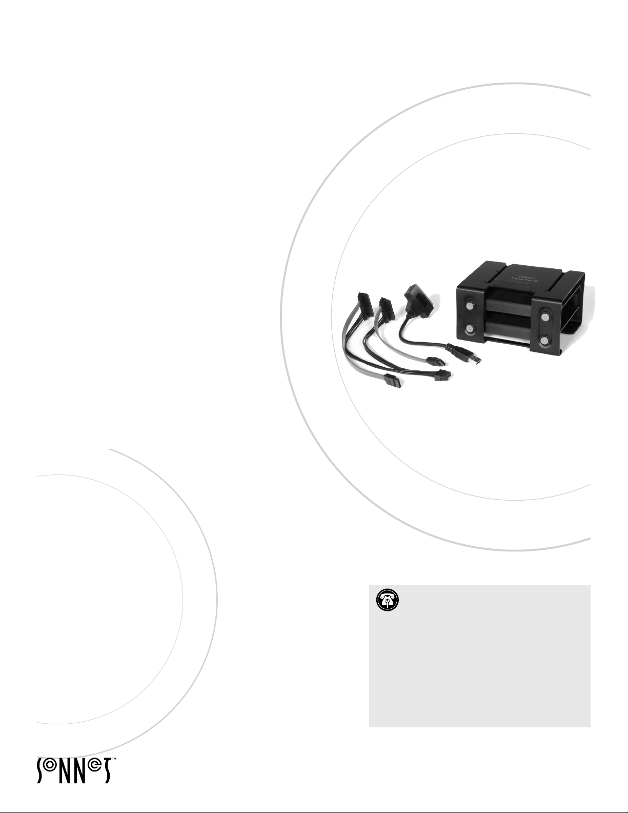
2. Using a Philips screwdriver, remove the four screws securing one
of the 2.5-inch SSD mounting plates in the primary bracket (two
on each side), set aside the screws, and then remove the plate
(Figure 1).
3. If you are installing more than one drive or SSD, repeat step 2 to
remove the remaining mounting plate. Otherwise, go to the next
step.
4. If you are installing only 2.5-inch SSDs, skip to step 9. Otherwise,
set the primary bracket down with the open side facing up
(Figure 2).
5. Remove a 3.5-inch drive from its packaging, handling the drive
by its edges. Insert the drive into the primary bracket with the
drive’s top label facing the top of the bracket and its connectors
on the left, and then align the holes in the bracket with the screw
holes in the drive (Figure 2).
2.5-inch drive
mounting plate
Figure 1
6. Using two of the previously removed 3.5-inch drive mounting
screws, secure the drive to the primary bracket, turning them
hand tight (Figure 2).
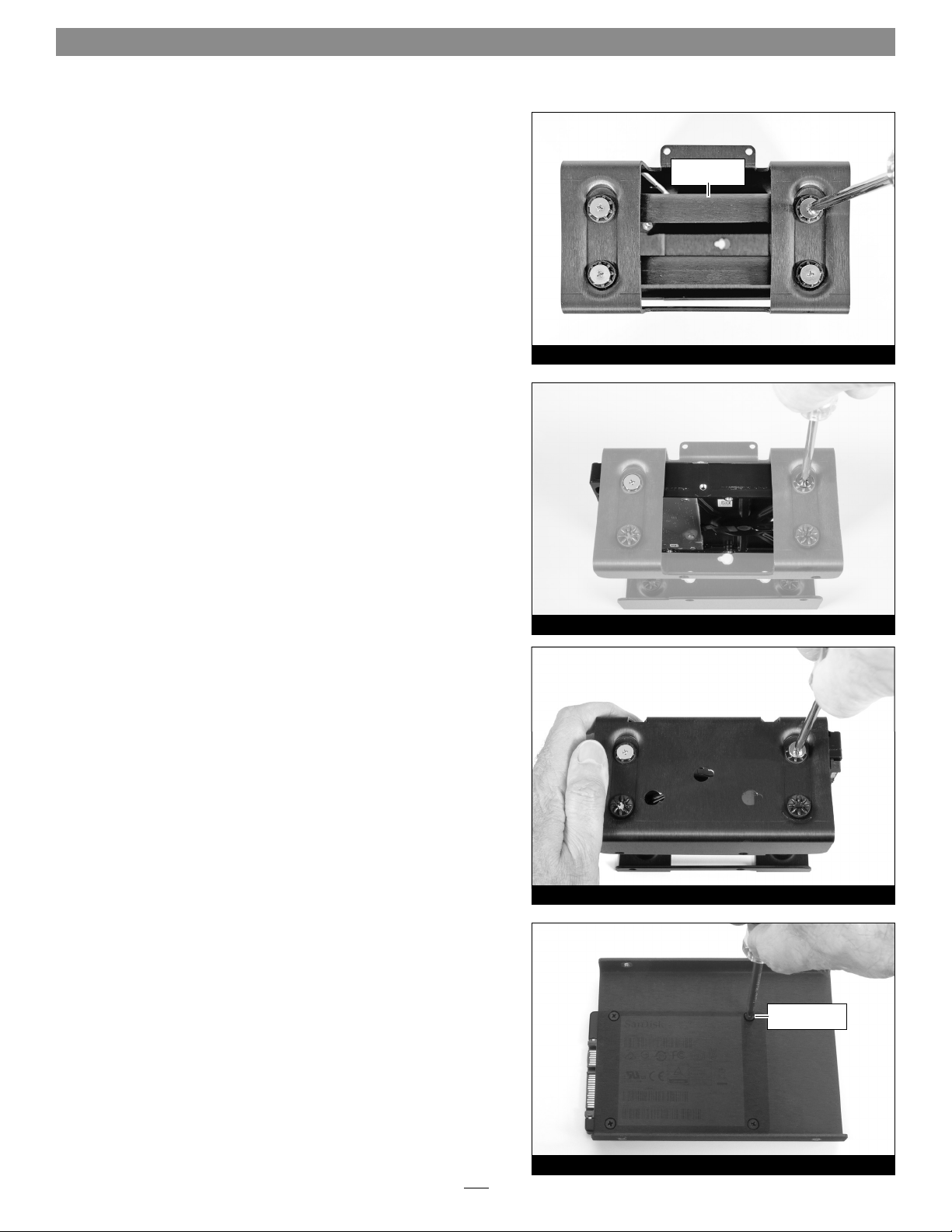
7. Supporting the drive, turn over the bracket. Using two of the
previously removed 3.5-inch drive mounting screws, finish
securing the drive to the primary bracket, turning them hand
tight (Figure 3).
8. If you are installing a second 3.5-inch drive, repeat steps 5–7 and
then skip to step 16. If you are installing a 2.5-inch SSD, go to the
next step. If you are done installing drives, skip to “Shut Down
and Open Computer” on the next page.
9. Remove a 2.5-inch SSD from its packaging, and then set it down
with the bottom label facing up and its connectors facing left
(Figure 4).
10. Place the 2.5-inch SSD mounting plate on top of the SSD as
shown, aligning the holes in the plate with the screw holes in the
SSD (Figure 4).
Figure 2
Figure 3
2.5-inch drive
mounting screws
11. Using four of the provided 2.5-inch SSD mounting screws, secure
the SSD to the mounting plate (Figure 4); do not overtighten
the screws.
Figure 4
2
Page 3
Fusion Flex J3i Installation Instructions
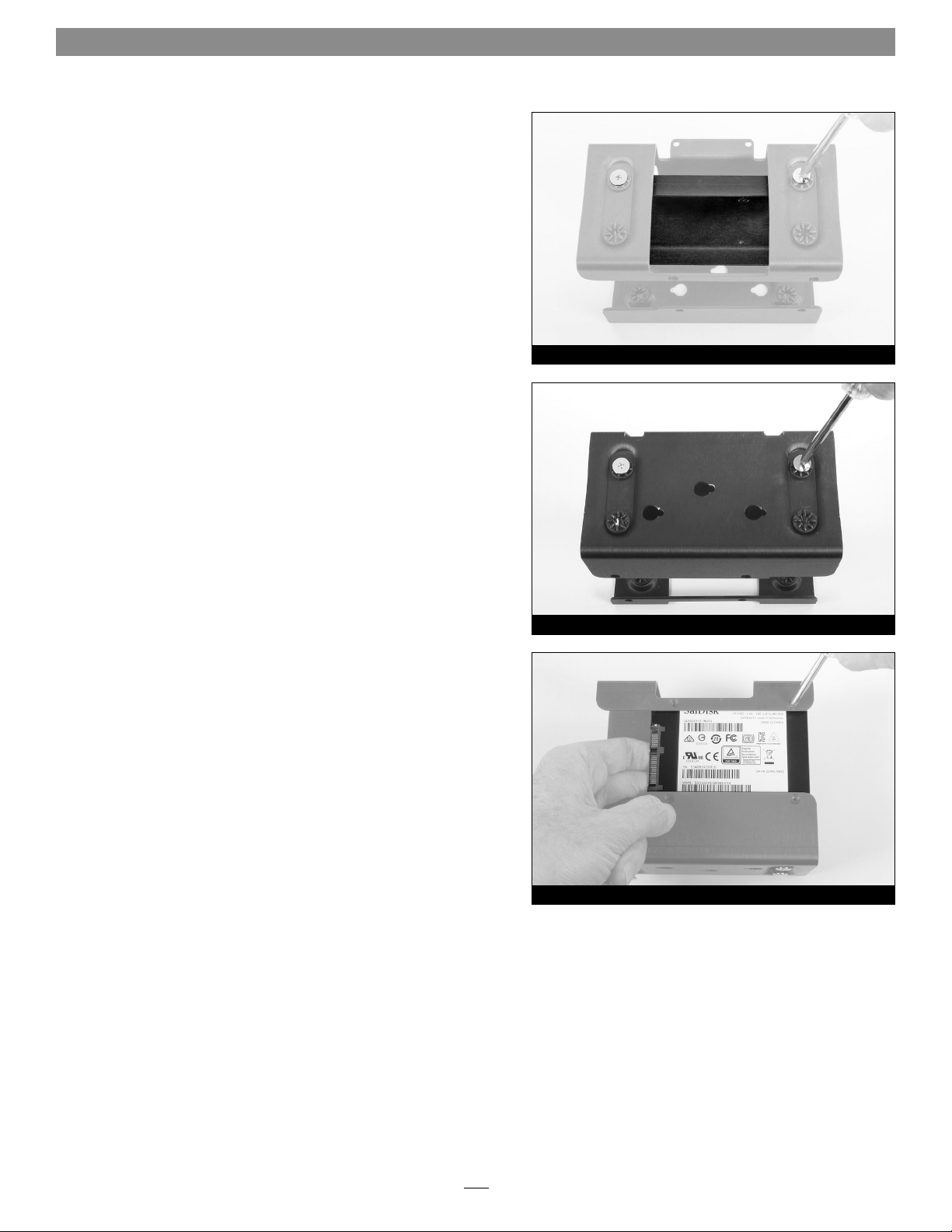
12. Insert the SSD mounting plate into the primary bracket with the
SSD’s top label facing the top of the bracket and its connectors
on the left, and then align the screw holes in the mounting plate
with the holes in the primary bracket (Figure 5).
13. Using two of the previously removed 3.5-inch drive mounting
screws, secure the 2.5-inch SSD mounting plate to the primary
bracket, turning the screws hand tight (Figure 5).
14. Supporting the mounting plate, turn over the bracket. Using two
of the previously removed 3.5-inch drive mounting screws, finish
securing the 2.5-inch SSD mounting plate to the primary bracket,
turning the screws hand tight (Figure 6).
15. If you are installing a second 2.5-inch SSD, repeat steps 9–14 and
then go to step 16; otherwise, go to the next step.
16. If you are installing a third drive (2.5-inch SSD), turn the
primary bracket so the bottom is face up and the installed drive’s
connectors facing left (Figure 7). Otherwise, go to “Shut Down
and Open Computer” below.
Figure 5
17. Remove the 2.5-inch SSD from its packaging, and then set it
down with its bottom label facing up and its connectors facing
left (Figure 7).
18. Insert the SSD into the primary bracket as shown, aligning
the SSD’s screw holes with the mounting holes in the bracket
(Figure 7).
19. While holding the SSD against the bracket, use four of the
provided 2.5-inch SSD mounting screws to secure the SSD to the
bracket (Figure 7); do not overtighten the screws.
Shut Down and Open Computer
1. Shut down your Mac Pro and wait 5–10 minutes to allow it to cool.
2. If you need to move the computer to a different area where you
can work freely, disconnect any connected cables, move the
computer, then reconnect the power cord between the computer
and an electrical outlet. (For the Mac Pro Rackmount, slide the
computer out of the rack. Note: You can install the Fusion Flex
J3i while the Mac Pro remains installed in the rack.)
3. Touch the metal on the outside of the computer to discharge any
potentially damaging static electricity.
Figure 6
Figure 7
4. Disconnect the power cord from the computer.
5. Remove the housing from the computer and set it aside. (For the
Mac Pro Rackmount, remove the top cover.)
3
Page 4

Fusion Flex J3i Installation Instructions
Install Assembled Fusion Flex J3i
Support Note: Although these instructions show the
installation of the Fusion Flex J3i into a Mac Pro desktop
computer, the installation steps are the same for the Mac Pro
Rackmount; when facing the back of the rackmount computer, the
mounting location inside is the bottom right corner.
1. Using a Torx T8 screwdriver or key, remove the two screws
securing the bracket cover plate at the top of the frame (Figure 8).
Set aside the screws and plate.
2. Make note of the three bracket mounting pins on the frame and
the three mounting pins on the logic board; you will secure the
Fusion Flex J3i assembly inside the computer using these pins
(Figure 8).
3. Plug in the 2-drive SATA data/power cable assembly cable to the
corresponding ports on the logic board (Figure 9); make sure the
connectors are plugged in securely.
4. If you did not install a third drive (2.5-inch SSD), go to the next
step. Otherwise, plug in the USB 3.0 to SATA data/power adapter
to the USB port on the logic board (Figure 9); make sure the
connector is plugged in securely.
bracket cover
plate
mounting pins
Figure 8
2-drive SATA data/power
cable assembly
USB 3.0 to SATA data /
power adapter cable
Torx T8 Scre wTorx T8 Scre w
5. Holding the Fusion Flex J3i with the product’s name on top,
align the slot openings on top of the primary bracket with the
front two mounting pins on the computer frame, and then slide
the bracket straight back on to all three frame mounting pins
(Figure 10). Push the bracket all the way back on to the logic
board mounting pins.
6. With the Fusion Flex J3i primary bracket’s top tab against the
computer’s frame, slide the bracket to the right until it stops; the
tab should be centered between the two screw holes in the frame
(Figure 11).
Figure 9
slot opening
Figure 10
tab
Figure 11
4
Page 5

Fusion Flex J3i Installation Instructions
7. Plug in the 2-drive SATA data/power cable assembly’s connectors
to the corresponding connectors of the top two drives (Figure 12);
make sure the connectors are plugged in securely.
8. If you did not install a third drive (2.5-inch SSD), skip to the next
step. Otherwise, plug in the USB 3.0 to SATA data/power adapter
cable to the SSD (Figure 13).
2-drive SATA data/power cable assembly
Figure 12
USB 3.0 to SATA data /power adapter c able
9. Place the computer’s bracket cover plate over the Fusion Flex J3i’s
top tab, aligning the cover plate’s holes with the screw holes in
the computer’s frame (Figure 14).
10. Insert both previously removed Torx T8 screws and screw them
into the frame part way, and then tighten one side, then the
other, going back and forth so the cover plate stays level (Figure
14); do not overtighten the screws.
Close Computer
Replace the cover and return the computer to your computing area if
necessary, and reconnect the power cord and peripheral cables to the
computer. Your installation is complete.
Figure 13
bracket cover
plate
Torx T8 Scre w Torx T8 Scre w
Figure 14
Format Drives
Use Disk Utility (found in the Utilities folder within the Applications
folder) to format installed drives.
5
Page 6

This Page Left Intentionally Blank
 Loading...