

Page 1
Quick Start Guide for Encore/ST G4
Power Mac and Operating System Compatibility
This Encore/ST G4 processor upgrade card is compatible only with Power Mac®G4
AGP Graphics, Gigabit Ethernet, Digital Audio, and QuickSilver 2001 models.
Installation of this product into a Power Mac G4 Cube is also supported, and requires a
Cube Installation Kit (sold separately); professional installation is strongly recommended.
If you are unsure which Power Mac model you have, refer to
the online Apple article that describes the differences at
http://docs.info.apple.com/article.html?artnum=58418.
This article lists model numbers, and describes physical
aspects of the various Power Mac G4 models.
At this printing, the Encore/ST G4 processor upgrade is compatible with Mac OS 9.2.1 through OS X version 10.2.3. For up-todate Mac OS compatibility information, check our web site.
The Encore/ST G4 supports hard disk and display sleep in all compatible Power Mac G4 computers; in some configurations, deep sleep may
not be supported.
You Should Have
The following items should be included in your product package:
• Encore/ST G4 processor upgrade card
• Processor card extension plate*
• Two extension plate mounting screws* (screwed into extension plate)
*
Only required for installation of the Encore/ST in Gigabit Ethernet and Digital Audio models originally
shipped with dual processors.
The following items are required for installation:
• Medium Phillips screwdriver
• Flat blade screwdriver
• Needle-nose pliers
Support Notes: Please familiarize yourself with the following instruc-
tions before beginning the installation. If you feel you are unable to install
the computer hardware, please contact a qualified computer technician. Sonnet
strongly recommends that a qualified technician perform this installation.
Before proceeding with the installation, we recommend that you make a backup
of important information on your hard drive prior to installing new hardware or
software.
WARNING: In order for the Encore/ST G4 to oper-
ate in your system, Mac OS 9.2.1 (or later), and the
latest Power Mac G4 firmware must be installed. If your
system does not meet these criteria, you must upgrade to OS
9.2.1 (or later) and update your system’s firmware before
installing this upgrade. Otherwise, your system will not operate with the Encore/ST installed. Instructions follow.
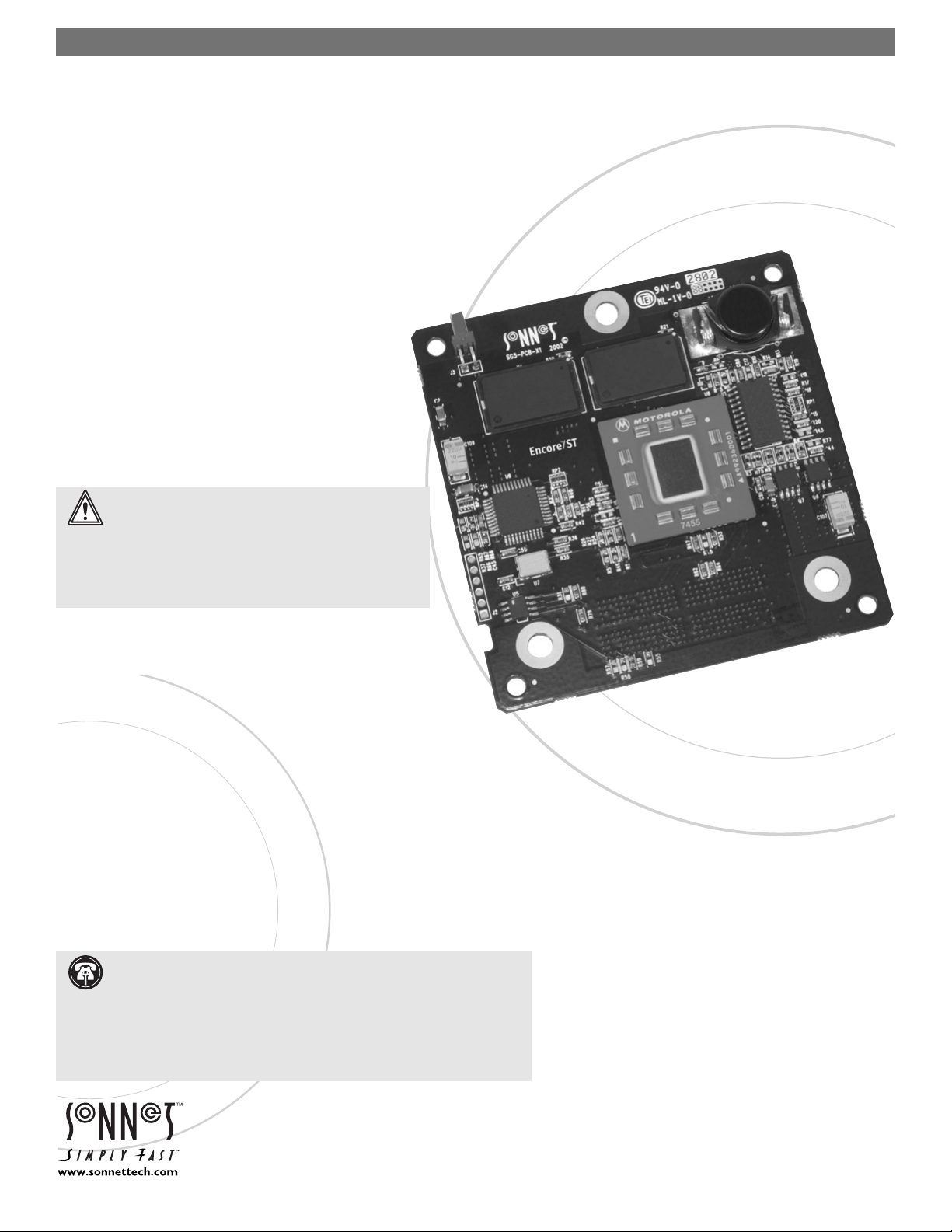
ENCORE
™
/
ST G4
Processor Upgrade Card for Power Mac® G4 AGP Graphics
Remember to register your product online at http://registration.sonnettech.com to be informed of future upgrades and product releases.
Software updates and links are available from the Sonnet web site at www.sonnettech.com.
•
Online support form available at http://supportform.sonnettech.com.
Sonnet Technologies Customer Service hours are Mon.-Fri., 7 a.m.–5 p.m. Pacific Time
•
Customer Service Phone: 1-949-472-2772 • E-mail: support@sonnettech.com
Sonnet Technologies, Inc., 15 Whatney, Irvine, California 92618-2808 USA • Tel:
1-
949-587-3500 Fax: 1-949-457-6350
©2002 Sonnet Technologies,Inc . All rights reserved. Sonnet,the Sonnet logotype, Simply Fast, the Simply Fast logotype, and Encore are trademarks of Sonnet Technologies, Inc. Macintosh and Mac are trademarks of Apple
Computer, Inc ., registered in the United States and other countries. Other product names are trademarks of their respective owners.Product specifications subject to change without notice. Printed in the USA.
QS-SG4-121802-E
Page 2
Multiple Upgrade Recommendation
If you intend to perform multiple hardware upgrades to your Power Mac, we
recommend that you complete the installation of the Encore/ST first, and then
install the remaining upgrades; complete each upgrade and test it before proceeding to
the next.
Install or Upgrade to Mac OS 9.2.1 or Later, If Necessary
The Encore/ST G4 requires Mac OS 9.2.1 or later in order to operate in your system, and must be installed before you install the processor upgrade card.
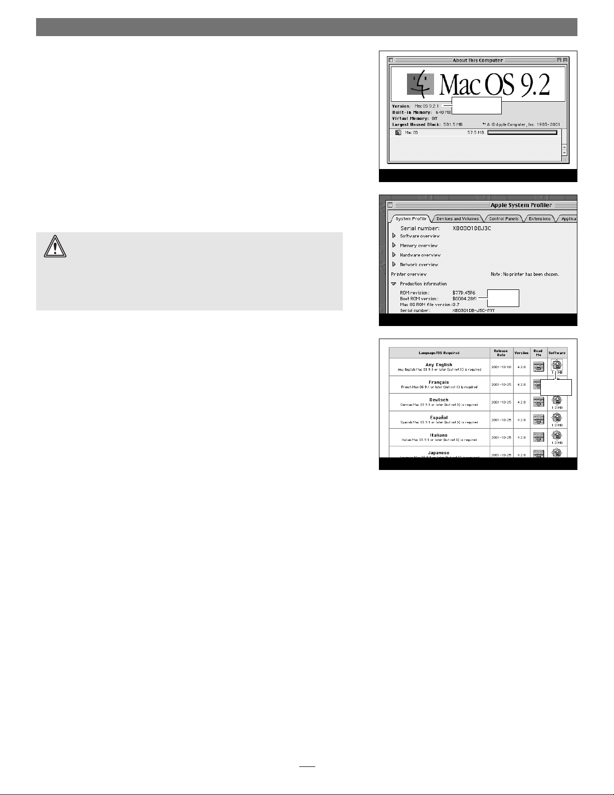
1. Verify the Mac OS version on your system is at least Mac OS 9.2.1, and then
install or upgrade the OS software if necessary (Figure 1).
Update Power Mac Firmware
Before installing the Encore/ST, you must ensure your AGP Graphics, Gigabit
Ethernet, or Digital Audio system’s firmware has been updated to the latest version (currently 4.2.8). Please note, your system must be able to make a connection to
the Internet to perform some of the steps in this section.
1. Boot your system in Mac OS 9.2.1 or later (not OS X, nor OS X Classic
mode). As of this writing, Apple has not made this firmware updater available as an OS X application.
2. From the Apple Menu, select and open Apple System Profiler. Click the trian-
gle next to Production Information, and find the Boot ROM version information (Figure 2). If it reads “$0004.28f1”, skip the rest of the steps in
this section and proceed to page 3. Otherwise, go to step 3.
3. Log on to the Internet and type the following in your browser window’s
address bar: http://docs.info.apple.com/article.html?artnum=120068.
4. Click on the appropriate software link to download the firmware software
(Figure 3).
5. Double-click the G4 FW Update 4.2.8.smi file icon to mount the G4
Firmware Update disk image.
6. Double-click the G4 Firmware Update icon to open the disk image, then
double-click the About G4 Firmware Update file icon. Once the read me file
has opened, print it.
7. Following the directions on the pages you printed, update the firmware on
your system. If a message appears stating that your firmware is up-to-date,
proceed to the next section.
Software and Firmware Installation/Update Info
2
Figure 2
Figure 3
Figure 1
Mac OS Version
information
firmware
version
software
link
WARNING: When you install (or upgrade to) Mac OS 9.2.1 or later, you
may have to upgrade the your computer’s firmware as part of the software installation. Please note, the firmware installed with the Mac OS may not
be the version required by the Encore/ST. Before installing the Encore/ST, you
may be required to upgrade your firmware again; you MUST ensure your
system is using version 4.2.8 firmware. If your system is using an earlier version
of the firmware, your system will not operate with the Encore/ST installed.
Page 3
3
This section covers the installation of the Encore/ST G4 into Power Mac AGP
Graphics and Gigabit Ethernet models. If you are installing this product into a
Digital Audio model, skip to page 6. If you are installing this product into a
QuickSilver 2001 model, skip to page 10.
Shut Down and Open Computer
1. Shut down your Power Mac. If the computer has been on, allow 20 minutes
for it to completely cool before beginning the installation.
2. If you need to move the computer to a different area where you can work
freely, disconnect any connected cables, move the computer, then reconnect
the power cord.
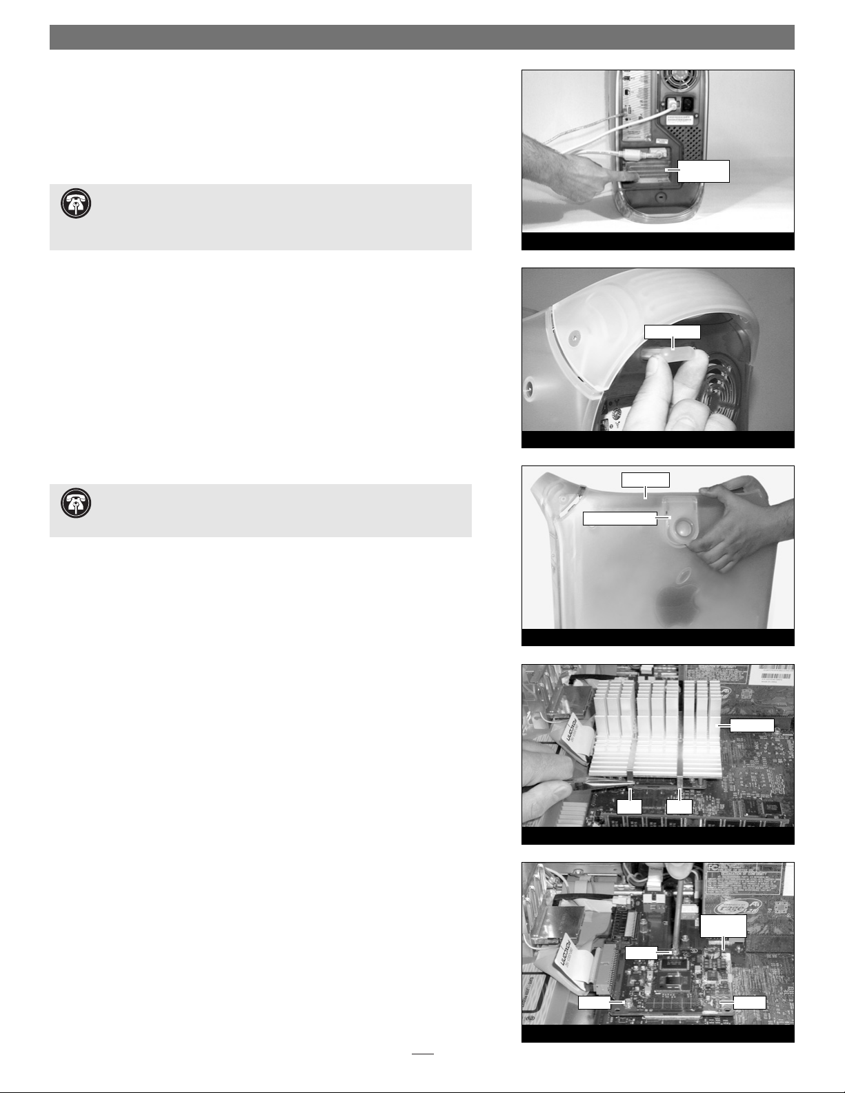
3. Touch a port access cover on the back of the computer (Figure 4) to dis-
charge any potentially damaging static electricity.
4. Disconnect the power cord from the computer.
5. Locate the security lock at the back of the computer (Figure 5). If it is not
already pressed in, do so now.
6. With the right side of the case facing you, open your Power Mac by lifting
the release latch and lowering the side panel away from the computer’s case
(Figure 6).
Remove Heat Sink
Locate the processor heat sink on the logic board (Figure 7); your heat sink may
appear different from what is pictured. Using caution to avoid touching the
processor card, grasp one of the clips securing the heat sink with needle-nose
pliers, between the heat sink and processor card. Pull down and away to unhook
one side of the clip from the processor card (Figure 6). Push the clip away from
you to unhook it from the other side. Repeat these steps with the other clip. Once
the clips have been unhooked, gently lift the heat sink and clips away from the
processor and set them aside, but not on the logic board.
Remove Processor Card
Remove the three screws securing the processor card to the logic board (Figure 8).
Grasping the processor card by its edges, carefully lift it straight up and away from
the logic board.
Installation—AGP Graphics and Gigabit Ethernet Models
Figure 7
Figure 8
clip clip
processor
card
heat sink
screw
screw
screw
Figure 6
raise release latch
side panel
Figure 5
security lock
Figure 4
port access
cover
Support Note: When handling computer products, take care to prevent
components from being damaged by static electricity; avoid working in
carpeted areas. Handle processor upgrade cards only by their edges and avoid
touching connector traces and component pins.
Support Note: To avoid generating a static charge in your body, do not
walk around the room until after you finish installing the Encore/ST card
and close the computer.
Page 4
Installation—AGP Graphics, Gigabit Ethernet Models
Install Encore/ST G4 Processor Upgrade Card
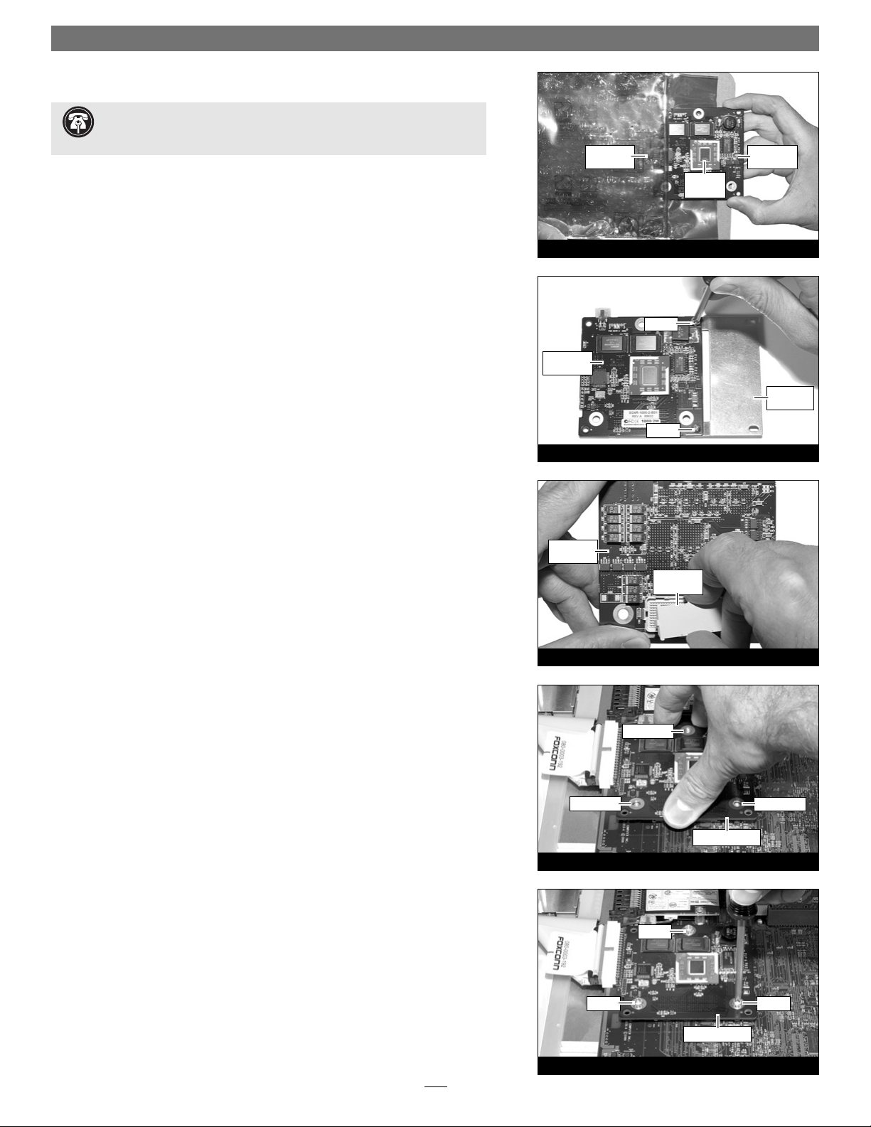
1. Remove the Encore/ST processor upgrade card from its anti-static package,
and remove the packing material. Make sure to handle the card by the edges
(Figure 9). Also, do not touch the thermal pad covering the processor.
2. If you removed a single-processor card from your system, skip to step 3. If you
removed a dual processor card, remove the extension plate and two screws
from the parts bag included with the Encore/ST, and then remove the screws
from the extension plate. With the Sonnet logo side of the board face up,
place the Encore/ST processor card on top of the extension plate (support
foot face down) as shown (Figure 10). Secure the Encore/ST card to the
extension plate with the two provided screws; do not overtighten the screws.
Please note, when attached properly, the extension plate will be level with the
Encore/ST board.
3. Hold the Encore/ST card with its connector facing up (Figure 11). Carefully
remove the cap covering the connector; place the cap on the original processor card’s connector. Place the processor card you removed from the computer into the anti-static package and store it in a safe place.
4. Align the Encore/ST card’s three screw holes with the three threaded posts
on the logic board, then set the card gently on top of the posts (Figure 12).
Make sure the connectors are lined up, then, grasping the card by its edges,
gently press it straight down until the connectors snap together. Verify the
connectors are completely coupled by gently pulling up on the edges of the
Encore/ST board; the board should remain firmly in place.
5. Snugly secure the Encore/ST card to the logic board with the three screws
you removed previously; do not overtighten the screws (Figure 13).
4
Figure 13
screw
screw
screw
Figure 12
Encore/ST card
Encore/ST card
Figure 11
screw hole
screw hole
screw hole
Figure 10
protective
cap
Figure 9
extension
plate
Encore/ST
card
Encore/ST
card
anti-static
package
Encore/ST
card
screw
screw
Support Note: You will find a piece of foam covering a connector on
the edge of the Encore/ST card. Do not remove the foam; the connector
is not used in this installation.
thermal
pad
Page 5

Figure 14
5
Reattach Heat Sink
1. The heat sink clips must be positioned properly on the heat sink. Examine
the clips and note the short and long sections, and the dimple. When you
reattach the heat sink, each clip will be placed on the heat sink so its long
section rests in the tall fin area. (Figure 14) Please note, this may be oppo-
site of how the clips were originally installed.
2. Set the clips aside. With the heat sink’s tall fins at the back, guide the heat
sink’s posts into the holes on the Encore/ST card; place the clips across the
heat sink, with the long sections resting in the tall fin area; make sure the
clips do not get caught between the card and the heat sink (Figure 15).
Verify that the heat sink is resting flat and level across the top of the
Encore/ST card.
3. Lift up a clip and hook it over the back edge of the Encore/ST card, then pull
it toward you (Figure 16). Repeat this process with the other clip.
4. Grasp a clip with needle-nose pliers, then pull it toward you and over the
front edges of the heat sink and the Encore/ST card (Figure 17); be careful
not to touch the Encore/ST card with the pliers, and be sure that the clip
is grasping the card at both ends. Repeat this process with the other clip.
5. Visually inspect all four points where the clips attach to the Encore/ST card.
It is easy for the clips to be attached only to the heat sink, which can lead to
destructive overheating of your upgrade card. Verify that each clip is grasping
the card at each end.
Close Computer
1. Raise the side panel back into place (Figure 18).
2. Return the computer to your computing area if necessary, and reconnect the
power cord and peripheral cables to the computer.
Turn On Computer
Turn on your Power Mac; your accelerated machine should boot normally. Your
installation is now complete.
Installation—AGP Graphics, Gigabit Ethernet Models
Figure 17
clip clip
Encore/ST
card
Figure 16
heat sink
clip
Figure 15
clip
clip
post
post
short
section
long
section
dimple
clip
heat sink
heat sink
fins
clip
Figure 18
release latch
side panel
WARNING: Your Power Macintosh was designed to operate efficiently
with the side panel closed. Do not operate your computer with the
side panel open; proper air flow over the heat sink will not occur and the
processor may overheat.
WARNING: The heat sink must be secured firmly, flatly and completely
for reliable and stable operation. If the clips are not properly attached to
the Encore/ST card at all four contact points, proper cooling of the processor
will not occur and the processor will overheat, causing severe damage to the
Encore/ST card. Repairs due to this damage are not covered by warranty.
Support Note: The following steps address the installation of your
system’s heat sink. Please note, only the single processor heat sink is pictured, but the procedure is identical for the dual processor heat sink. Please also
note, that your heat sink may differ from what is pictured.
Encore/ST
card
Page 6

Installation—Digital Audio Models
This section covers the installation of the Encore/ST G4 into Power Mac G4
Digital Audio models (back panel appears like Figure 20). If you are installing this
product into an AGP Graphics or Gigabit Ethernet model, go back to page 3. If
you are installing this product into a QuickSilver 2001 model, skip to page 10.
Shut Down and Open Computer
1. Shut down your Power Mac. If the computer has been on, allow 20 minutes
for it to completely cool before beginning the installation.
2. If you need to move the computer to a different area where you can work
freely, disconnect any connected cables, move the computer, then reconnect
the power cord.
3. Touch a port access cover on the back of the computer to discharge any
potential damaging static electricity (Figure 19).
4. Disconnect the power cord from the computer.
5. If present, remove the two indicated screws from the back plate of the com-
puter (Figure 20). Otherwise, go to step 6.
6. Locate the security lock at the back of the computer (Figure 21). If it is not
already pressed in, do so now.
7. With the right side of the case facing you, open your Power Mac by lifting
the release latch and lowering the side panel away from the computer’s case
(Figure 22).
Remove Fan Assembly
This section covers the removal of the fan assembly found on some Digital Audio
models. If your machine does not have a fan assembly covering the processor
heat sink, skip to “Remove Heat Sink” on the next page.
1. Locate and carefully disconnect the 2-pin connector from the processor card
(Figure 23).
6
Support Note: To avoid generating a static charge in your body, do not
walk around the room until after you finish installing the Encore/ST card
and close the computer.
Figure 22
Figure 23
2-pin
connector
Figure 21
raise release latch
side panel
Figure 20
security lock
Figure 19
port access
cover
Generic G4
model shown
screw
screw
sound ports
Support Note: When handling computer products, take care to prevent
components from being damaged by static electricity; avoid working in
carpeted areas. Handle processor upgrade cards only by their edges and avoid
touching connector traces and component pins.
processor
card
Page 7

Installation—Digital Audio Models
2. Unlatch the fan assembly’s clips from the processor card and the heat sink,
then lift the fan assembly out of the case and set it aside (Figure 24).
Remove Heat Sink
Locate the clips securing the processor heat sink to the processor card (Figure 25);
your heat sink may appear different from what is pictured. Using caution to
avoid touching the processor card, grasp one of the clips securing the heat sink
with needle-nose pliers, between the heat sink and processor card. Pull down and
away to unhook one side of the clip from the processor card (Figure 25). Push
the clip away from you to unhook it from the other side. Repeat these steps with
the other clip. Once the clips have been unhooked, gently lift the heat sink and
clips away from the processor and set them aside, but not on the logic board.
Remove Processor Card
Remove the three screws securing the processor card to the logic board
(Figure 26). Grasping the processor card by its edges, carefully lift it straight up
and away from the logic board.
Install Encore/ST G4 Processor Upgrade Card
1. Remove the Encore/ST processor upgrade card from its anti-static package,
and remove the packing material. Make sure to handle the card by the edges
(Figure 27). Also, do not touch the thermal pad covering the processor.
2. If you removed a single processor CPU card from your system, skip to step 3. If you
removed a dual processor card, remove the extension plate and two screws
from the parts bag included with the Encore/ST, and then remove the screws
from the extension plate. With the Sonnet logo side of the board face up,
place the Encore/ST processor card on top of the extension plate (support
foot face down) as shown (Figure 28). Secure the Encore/ST card to the
extension plate with the two provided screws; do not overtighten the screws.
Please note, when attached properly, the extension plate will be level with the
Encore/ST board.
7
Figure 27
Figure 28
Figure 26
Figure 25
Figure 24
clip
clip
heat sink
fan assembly
processor
card
screw
screw
clip (grasp here)
clip (grasp here)
screw
Encore/ST
card
screw
screw
extension
plate
Support Note: You will find a piece of foam covering a connector on
the edge of the Encore/ST card. Do not remove the foam until instructed
to do so.
anti-static
package
Encore/ST
card
thermal
pad
Page 8

3. Hold the Encore/ST card with its connector facing up (Figure 29). Carefully
remove the cap covering the connector and place it on the original processor
card’s connector, then place the original processor card into the anti-static
package and store it in a safe place.
4. Align the Encore/ST card’s three screw holes with the three threaded posts
on the logic board, then set the card gently on top of the posts (Figure 30).
Make sure the connectors are lined up, then, grasping the card by its edges,
gently press it straight down until the connectors snap together. Verify the
connectors are completely coupled by gently pulling up on the edges of the
Encore/ST board; the board should remain firmly in place.
5. Snugly secure the Encore/ST card to the logic board with the three screws
you removed previously; do not overtighten the screws (Figure 31).
Reattach Heat Sink
1. Position the heat sink clips properly on the heat sink (Figure 32). Examine
the clips and note the short and long sections, and the dimple. Place each
clip so its short section is closest to you (on the notched side of the heat
sink). Please note, this may be opposite of how the clips were originally
installed.
2. Grasping the heat sink with the notch facing you, guide the heat sink’s posts
into the holes on the Encore/ST card; make sure the clips do not get caught
between the card and the heat sink (Figure 33). Verify that the heat sink is
resting flat and level across the top of the Encore/ST card.
Installation—Digital Audio Models
8
Figure 31
Figure 30
screw
screw screw
Encore/ST
card
screw hole
screw hole
screw hole
Support Note: The following steps address the installation of your
system’s heat sink. Please note, only the single processor heat sink is pictured, but the procedure is identical for the dual processor heat sink. Please also
note, that your heat sink may differ from what is pictured.
Figure 33
Encore/ST
card
hole
hole
heat sink
Figure 32
dimple
dimple
clip
notch
clip
short
section
long
section
heat sink
Figure 29
protective
cap
Encore/ST
card
Page 9

3. Lift up a clip and hook it over the back edge of the Encore/ST card, then pull
it toward you. Repeat this process with the other clip. Grasp a clip with needle-nose pliers, then pull it toward you and over the front edges of the heat
sink and the Encore/ST card (Figure 34); be careful not to touch the
Encore/ST card with the pliers, and be sure that the clip is grasping the
card at both ends. Repeat this process with the other clip.
4. Visually inspect all four points where the clips attach to the Encore/ST card.
It is easy for the clips to be attached only to the heat sink, which can lead to
destructive overheating of your upgrade card. Verify that each clip is grasping
the card at each end.
Reinstall Fan Assembly and Close Computer
1. Slide the fan assembly back over the heat sink, making sure the fan assem-
bly’s clips engage the Encore/ST card and the heat sink (Figure 35). Remove
the foam covering the 2-pin connector on the edge of the Encore/ST card,
and then carefully plug in the fan’s 2-pin connector (Figure 35).
2. Raise the side panel back into place (Figure 36).
3. Using the two screws you removed previously, secure the fan assembly to the
back plate of the computer (Figure 37).
4. Return the computer to your computing area if necessary, and reconnect the
power cord and peripheral cables to the computer.
Turn On Computer
Turn on your Power Mac; your accelerated machine should boot normally. Your
installation is now complete.
Installation—Digital Audio Models
9
Figure 37
Figure 36
raise release latch
screw
screw
side panel
Figure 35
fan assembly
Encore/ST
card
2-pin
connector
Support Note: The Encore/ST processor card operates reliably in Power
Mac G4 Digital Audio models with or without a fan covering the heat
sink. If your system does not have a fan assembly, leave the piece of foam covering the 2-pin connector on the edge of the Encore/ST card in place; skip steps 1
and 3 of “Reinstall Fan Assembly and Close Computer”.
Figure 34
Encore/ST
card
clip clip
WARNING: The heat sink must be secured firmly, flatly and completely
for reliable and stable operation. If the clips are not properly attached to
the Encore/ST card at all four contact points, proper cooling of the processor
will not occur and the processor will overheat, causing severe damage to the
Encore/ST card. Repairs due to this damage are not covered by warranty.
Page 10

Installation—QuickSilver 2001 Models
10
Figure 41
Figure 42
Figure 40
Figure 39
security lock
Figure 38
port access
cover
fan
assembly
2-pin
connector
This section covers the installation of the Encore/ST G4 into Power Mac G4
QuickSilver 2001 models. If you are installing this product into an AGP Graphics
or Gigabit Ethernet model, go back to page 3. If you are installing this product
into a Digital Audio model, go back to page 6.
Shut Down and Open Computer
1. Shut down your Power Mac. If the computer has been on, allow 20 minutes
for it to completely cool before beginning the installation.
2. If you need to move the computer to a different area where you can work
freely, disconnect any connected cables, move the computer, then reconnect
the power cord.
3. Touch a port access cover on the back of the computer to discharge any
potential damaging static electricity (Figure 38).
4. Disconnect the power cord from the computer.
5. Locate the security lock at the back of the computer (Figure 39). If it is not
already pressed in, do so now.
6. With the right side of the case facing you, open your Power Mac by lifting
the release latch and lowering the side panel away from the computer’s case
(Figure 40).
Remove Fan Assembly
1. With the back of the computer facing you, remove the two indicated screws
(Figure 41).
2. Locate and carefully disconnect the 2-pin fan power connector from the
logic board, and then lift out the fan assembly (Figure 42).
Support Note: To avoid generating a static charge in your body, do not
walk around the room until after you finish installing the Encore card and
close the computer.
Support Note: When handling computer products, take care to prevent
components from being damaged by static electricity; avoid working in
carpeted areas. Handle processor upgrade cards only by their edges and avoid
touching connector traces and component pins.
raise release latch
side panel
screw screw
WARNING: The Encore/ST is not designed for installation into the Power
Mac G4 (QuickSilver 2002 [800MHz, 933MHz or Dual 1GHz]) models. Do
not attempt to install this product into those models.
Page 11

Installation—QuickSilver 2001 Models
11
Remove Heat Sink
With the front of the computer facing you, locate the clips securing the heat sink
to the processor card (Figure 43). Carefully insert a flat blade screwdriver between
the right clip and the edge of the heat sink; do not touch the edge of the
processor card. Using extreme caution, press down on the edge of the clip with
needle-nose pliers, and twist the screwdriver to unhook one side of the clip from
the processor card (Figure 43). Push the clip away from you to unhook it from
the other side. Repeat these steps with the left clip. Once the clips have been
unhooked, gently lift the heat sink and clips away from the processor card and set
them aside, but not on the logic board.
Remove Processor Card
1. Remove the four screws securing the processor card to the logic board
(Figure 44); set aside the indicated screw, and do not reuse it.
2. Grasping the processor card by its edges, carefully lift it straight up and away
from the logic board (Figure 45).
Install Encore/ST G4 Processor Upgrade Card
1. Remove the Encore processor upgrade card from its anti-static package, and
remove the packing material. Make sure to handle the card by the edges
(Figure 46). Also, do not touch the thermal pad covering the processor.
2. Hold the Encore/ST card with its connector facing up (Figure 47). Carefully
remove the cap covering the connector and place it on the original processor
card’s connector, then place the original processor card into the anti-static
package and store it in a safe place.
Figure 45
Figure 46
Figure 44
Figure 43
processor
card
screw
(do not
reuse)
screw
screw
screw
processor card
heat sink
clip
clip
anti-static
package
Encore/ST
card
Figure 47
Support Note: The following steps address the removal of your sys-
tem’s processor card heat sink. Please note, the dual processor heat sink is
pictured, but the procedure to remove the single processor heat sink is identical.
WARNING: Verify that the power cord is disconnected from your Power
Mac before you remove the heat sink and processor card. The original
processor card is secured to the logic board with four screws, one of which carries +12V and could spark if it is grounded when the system is on.
protective
cap
Encore/ST
card
Support Note: You will find a piece of foam covering a connector on
the edge of the Encore/ST card. Do not remove the foam; the connector
is not used in this installation.
thermal
pad
processor
card
Page 12

Installation—QuickSilver 2001 Models
12
3. Align the Encore/ST card’s three screw holes with the three threaded posts
on the logic board, then set the card gently on top of the posts (Figure 48).
Make sure the connectors are lined up, then, grasping the card by its edges,
gently press it straight down until the connectors snap together. Verify the
connectors are completely coupled by gently pulling up on the edges of the
Encore/ST board; the board should remain firmly in place.
4. Snugly secure the Encore/ST card to the logic board with the three screws
you removed previously; do not overtighten the screws (Figure 49).
Reattach Heat Sink
1. Make sure the heat sink clips are positioned properly on the heat sink
(Figure 50); your heat sink may differ from what is pictured. Examine each
clip and note the tab on the edge. Place each clip so its tab fits into the
groove on the heat sink, and the clip drops to the bottom of the heat sink’s
fins.
2. Guide the heat sink’s mounting posts into the holes on the Encore/ST card;
make sure the clips do not get caught between the card and the heat sink
(Figure 51). Verify that the heat sink is resting flat and level across the top of
the Encore card.
3. Lift up a clip and hook it over the back edge of the Encore card, then pull it
toward you. Repeat this process with the other clip. Carefully insert a flat
blade screwdriver between the left clip and the edge of the heat sink; do not
touch the edge of the processor card. Using extreme caution, press down
on the edge of the clip with needle-nose pliers, and twist the screwdriver to
hook the clip over the edge of the Encore/ST card. Be certain that the clip is
grasping the card at both ends. Repeat this process with the other clip
(Figure 52).
4. Visually inspect all four points where the clips attach to the Encore/ST card.
It is easy for the clips to be attached only to the heat sink, which can lead to
destructive overheating of your upgrade card. Verify that each clip is grasping
the card at each end.
Support Note: The following steps address the installation of your
system’s heat sink. Please note, only the single processor heat sink is pictured, but the procedure is similar for the dual processor heat sink. Please also
note, that your heatsink may differ from what is pictured.
Figure 50
Figure 51
Figure 49
Encore/ST
card
tab
clip clip
groove
Figure 52
screw
screw
screw
Encore/ST
card
heat sink
heat sink
heat sink
clip
clip
WARNING: The heat sink must be secured firmly, flatly and completely
for reliable and stable operation. If the clips are not properly attached to
the Encore card at all four contact points, proper cooling of the processor will
not occur and the processor will overheat, causing severe damage to the Encore
card. Repairs due to this damage are not covered by warranty.
Figure 48
Encore/ST
card
screw hole
screw hole
screw hole
Page 13

Installation—QuickSilver 2001 Models
13
Reinstall Fan Assembly and Close Computer
1. While holding its 2-pin connector, place the fan assembly between the
heat sink and the back panel of the computer, against the modem filter
(Figure 53). Carefully plug in the fan’s 2-pin connector to the connector on
the logic board (Figure 53).
2. With the back of the computer facing you, secure the fan assembly to the
back plate of the computer with the two screws you removed previously
(Figure 54).
3. Raise the side panel back into place (Figure 55).
4. Return the computer to your computing area if necessary, and reconnect the
power cord and peripheral cables to the computer.
Turn On Computer
Turn on your Power Mac; your accelerated machine should boot normally. Your
installation is now complete.
Figure 54
Figure 55
raise release latch
side panel
screw screw
Figure 53
2-pin
connector
modem
filter
fan assembly
 Loading...