

Page 1

Aria™ extreme 54 Mbps Wireless LAN
CardBus Card or PCI Card
Windows User’s Manual
Page 2

2004 Sonnet Technologies, Inc. All rights reserved. Sonnet, the Sonnet logotype, Simply
Fast, the Simply Fast logotype, and Aria are trademarks of Sonnet Technologies, Inc.
Microsoft and Windows are registered trademarks of Microsoft Corporation. Other product
names are trademarks of their respective owners. No part of this document may be reproduced
or transmitted in any form or by any means, electronic or mechanical, for any purpose,
without the express written permission of Sonnet.
Disclaimer
Information in this document is subject to change without notice. The material contained
herein is supplied without representation or warranty of any kind. Sonnet therefore assumes no
responsibility and shall have no liability of any kind arising from the supply or use of this
document or the material contained herein.
II
Page 3

About This Manual
The following terms and abbreviations are used interchangeably:
• Access Point – AP
• Peer-to-Peer (Computer-to-Computer) – Ad-Hoc
• Wireless LAN – WLAN
• Ethernet network – LAN – network
This User’s Manual contains information on how to install and configure your Aria extreme
CardBus card or Aria extreme PCI card. From this point forward, you will be guided through
the correct configuration steps to get your device up and running.
802.11g Compliance Notice
This wireless device supports the final draft 802.11g specification, which has been ratified by
the IEEE.
III
Page 4

Contents
Chapter 1—Introduction...................................................................................................................................................... 1
Wireless LAN Basics.............................................................................................................................................................. 2
Local Area Network (LAN).................................................................................................................................................................... 2
Ad-Hoc Mode....................................................................................................................................................................................... 3
Infrastructure Mode .............................................................................................................................................................................4
Roaming (Aria extreme CardBus) .........................................................................................................................................................5
Chapter 2—Installing the Aria extreme Card and Software........................................................................................... 7
System Requirements............................................................................................................................................................. 8
Installing the Aria extreme PCI Adapter Card......................................................................................................................... 9
Basic Installation Procedure .................................................................................................................................................................. 9
Installing the Wireless LAN Driver and Software..................................................................................................................11
Basic Installation Procedures ................................................................................................................................................11
General Guidelines for OS-Specific Situations ...................................................................................................................................... 15
Chapter 3—Using the Wireless LAN Utility ...................................................................................................................17
Launching the Wireless LAN Utility......................................................................................................................................18
Note About Using the Wireless LAN Utility Under Windows XP .........................................................................................................19
Chapter 4—Using Wireless Tray Icon Functions............................................................................................................35
Viewing Signal Strength Information...................................................................................................................................... 35
Chapter 5—Windows XP Wireless Zero Configuration Utility.................................................................................... 39
IV
Page 5

Connecting to an Access Point or Wireless LAN Card.........................................................................................................39
Viewing the Wireless Connection Status ..............................................................................................................................42
Configuring the Wireless Connection Properties.................................................................................................................. 43
Chapter 6—Uninstalling the Aria extreme...................................................................................................................... 49
Uninstalling the Wireless LAN Card Software ......................................................................................................................49
Removing the Aria extreme Card......................................................................................................................................... 52
Chapter 7—Troubleshooting............................................................................................................................................. 53
Verify the Aria extreme is functioning properly ....................................................................................................................53
Cannot Install under Windows 2000 ....................................................................................................................................54
Radio Interference ...............................................................................................................................................................54
Appendix A—Limited Warranty.......................................................................................................................................59
Wireless LAN Hardware .....................................................................................................................................................59
Appendix B—Regulatory Compliance .............................................................................................................................. 61
FCC Part 15 Declaration of Conformity (DoC) .................................................................................................................... 61
FCC Rules and Regulations - Part 15 ....................................................................................................................................62
FCC Radiation Exposure Statement......................................................................................................................................63
Appendix C—Setting Up TCP/IP ......................................................................................................................................65
For Windows 2000/XP ........................................................................................................................................................68
Appendix D Specifications..................................................................................................................................................71
V
Page 6

Glossary ................................................................................................................................................................................ 74
VI
Page 7

List of Figures
Figure 1-1 Ad-Hoc Mode..........................................................................................................................................................................................................3
Figure 1-2 Infrastructure Mode..............................................................................................................................................................................................4
Figure 1-3 Roaming Across Multiple Access Points......................................................................................................................................................5
Figure 3-1 Link Status Tab.....................................................................................................................................................................................................23
Figure 3-2 Configuration Tab...............................................................................................................................................................................................27
Figure 3-3 Encryption Tab..................................................................................................................................................................................................... 29
Figure 3-5 Site Monitor Tab .................................................................................................................................................................................................32
Figure 3-6 About Tab ..............................................................................................................................................................................................................33
Figure 5-1 Windows XP Configuration Utility-Connect to Wireless Network........................................................................................... 40
Figure 5-2 Windows XP- Connection Status................................................................................................................................................................ 42
Figure 5-3 Windows XP Connection Properties -General .................................................................................................................................... 43
Figure 5-4 Windows XP Connection Properties-Wireless Networks ............................................................................................................. 44
Figure 5-5 Windows XP-Add Preferred Networks................................................................................................................................................... 45
Figure 5-6 Windows XP Configuration Utility-Set up a Network to Aceess................................................................................................ 47
Figure 5-7 Windows XP Connection Properties – Authentication.................................................................................................................... 48
VII
Page 8

Page 9

Chapter 1—Introduction
The Aria extreme is a cross-platform, high-speed 802.11g wireless LAN adapter (CardBus or
PCI) card. It enables your computer to connect to a wireless network and access the Internet,
and share resources, such as files and networked printers, without being bound to network
wires.
Operating in 2.4GHz Direct Sequence Spread Spectrum (DSSS) radio transmission range, the
Aria extreme transfers data at speeds up to 54Mbps when communicating with other 802.11g
devices, but is also backward compatible with 802.11b (Wi-Fi) devices. Both Ad-Hoc and
Infrastructure modes are supported, and for network security concerns, the 64/128-bits Wired
Equivalent Protection (WEP) algorithm is used. In addition, its standard compliance ensures
that it can communicate with any 802.11b/g network.
1
Page 10

Wireless LAN Basics
This section contains some basic information to help you better understand how the Aria
extreme works with other devices to create and operate within a wireless network.
Local Area Network (LAN)
Simply put, a LAN is a network that exists in a relatively limited area. A network consists of
two or more computers connected together, sharing files and peripheral devices such as
printers.
The Aria extreme enables your computer to interact with other computers without connecting
cables normally associated with networks. This makes it possible for you to move your
computer around while staying connected to your network.
There are two ways to use the Aria extreme. One way is to connect directly to one or more
Wireless LAN Card-equipped computers, forming an Ad-Hoc wireless network. The second
way is to connect to an Access Point, which gives you access to an existing wired LAN,
forming an Infrastructure wireless network.
2
Page 11
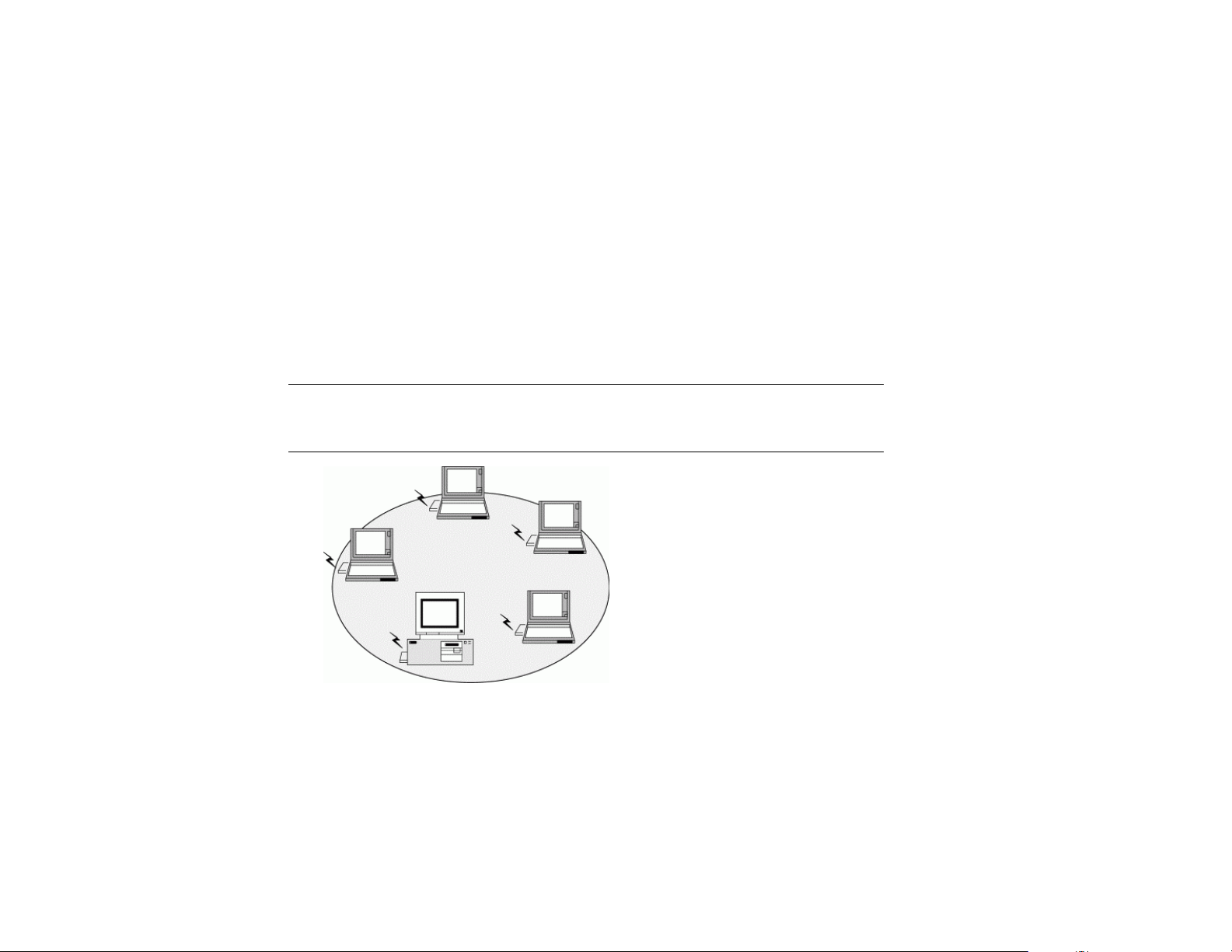
Ad-Hoc Mode
The Ad-Hoc Group offers peer-to-peer (computer to computer) connections between
workstations, enabling communication between computers within range that have a Wireless
LAN Card installed. A wireless Ad-Hoc network can also access a wired LAN‘s TCP/IP
services (such as e-mail and the Internet) by using a TCP/IP software router on an Ethernet
equipped Macintosh PowerBook or Windows notebook computer.
Note: Using the Aria extreme card in Ad-Hoc mode, your target peer can be a 802.11b or
802.11g- compatible wireless station, but not an 802.11a wireless station, since 802.11a
devices are not compatible with 802.11b/g devices.
Figure 1-1 Ad-Hoc Mode
3
Page 12

Infrastructure Mode
The Infrastructure network uses an Access Point (AP) or several APs as a gateway, linking the
wireless network to a wired LAN. As a result, portable and desktop computers on your
wireless network have access to all of the features of your wired LAN, including e-mail,
Internet access, networked printers and file servers.
Note: Using the Aria extreme in Infrastructure mode, you can connect to 802.11b and 802.11g
compatible Access Points, but not to an 802.11a AP, since 802.11a devices are not compatible
with 802.11b/g devices.
Figure 1-2 Infrastructure Mode
4
Page 13
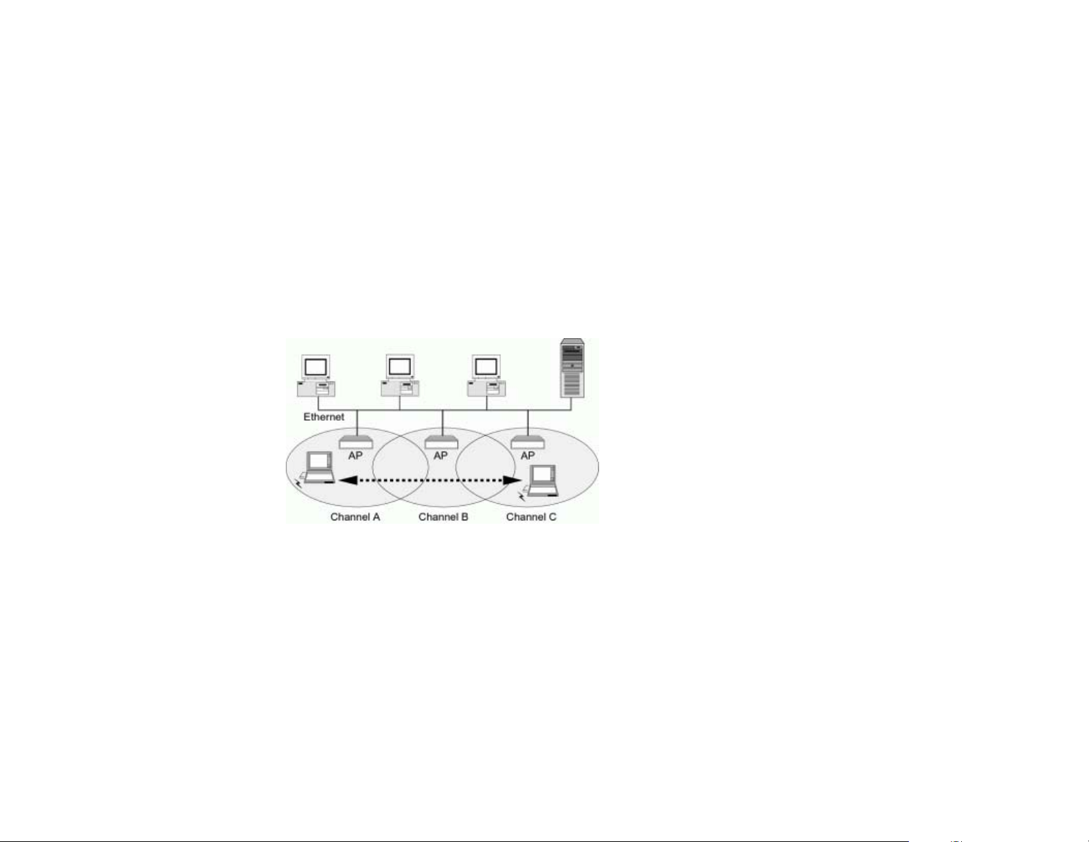
Roaming (Aria extreme CardBus)
Multiple Access Points can be installed to extend the wireless service coverage area for
seamless wireless access. Within an extended service area, all Access Points and wireless
clients must use the same Service Set Identity (SSID). When roaming among different Access
Points, wireless connectivity is maintained automatically at all times.
Figure 1-3 Roaming Across Multiple Access Points
5
Page 14

Page 15

Chapter 2—Installing the Aria extreme Card and Software
This chapter describes the process of driver and utility software installation for Aria extreme
CardBus and PCI cards; this chapter also describes the process of hardware installation for the
Aria extreme PCI card. The driver software enables the card to operate in your computer,
while the utility software, Wireless LAN Utility, helps you configure and monitor your Aria
extreme.
7
Page 16

54Mbps Wireless LAN Card User’s Manual
System Requirements
To use the Aria extreme, your computer must meet the following minimum requirements:
Pentium (or equivalent) processor, 300 MHz or better recommended
64MB of RAM, additional memory recommended
30 MB or more hard disk space
Windows
For Aria extreme (CardBus card): 32-bit CardBus expansion slot
For Aria extreme PCI: One available PCI slot
®
98SE/Me/2000/XP
8
Page 17

Chapter 2—Installing the Aria extreme Card and Software
Installing the Aria extreme PCI Adapter Card
This section covers the installation of the Aria extreme PCI into a desktop computer. If this
does not apply to you, skip to the page 11.
WARNING:
When handling computer products, you must take care to prevent components from being
damaged by static electricity. Before opening your computer or removing parts from their
packages, always ground yourself first by touching a metal part of the computer, such as a port
access cover, and work in an area free of static electricity; avoid carpeted area. Handle all
electronic components by their edges, and avoid touching connector traces and component
pins.
Basic Installation Procedure
1. Shut down your computer.
2. Open your computer to access the expansion card area (PCI slots); refer to your
computer’s user manual for specific info.
3. Locate an available PCI slot inside your computer and remove its port access cover, if
present, from the rear of the computer.
9
Page 18

54Mbps Wireless LAN Card User’s Manual
4. Remove the Aria extreme PCI card from its packaging, and screw in the included
5. If you will be connecting to a closed network and access is restricted to specific users,
6. Install the Aria extreme PCI card into the PCI slot; make sure the card is firmly seated
7. Close your computer and replace its cover.
WARNING:
When you turn on your system after installing the card, the Windows Plug-n-Play function
will detect the card and an installation dialog requesting its driver will appear; click Cancel to
quit the wizard. If you use the wizard, the correct software will NOT be installed. Follow the
instructions on the next page.
antenna.
write down the MAC number printed on a label affixed to the back of the card.
and secured.
10
Page 19

Chapter 2—Installing the Aria extreme Card and Software
Installing the Wireless LAN Driver and Software
WARNING:
If you have the Aria extreme CardBus card, do not plug it into your computer before installing
its driver. If you do, the Windows Plug-n-Play function will detect the card and a installation
dialog requesting its driver will appear; the proper software will NOT be installed. Click
Cancel to quit the wizard and remove the Wireless LAN Card from your computer, and then
follow the instructions below.
Basic Installation Procedures
Windows 98SE, Me, 2000 and XP use the same setup program; however, OS- (Operating
System) specific situations may occur during or after the driver installation process; the
following sections only describe general installation procedures. In OS-specific situations,
follow the on-screen instructions to proceed; you can refer to the general guidelines provided
in the next section on page 15 for further information.
Follow these steps to install the Wireless LAN Card driver and software.
1. Close all Windows programs that are running.
11
Page 20
54Mbps Wireless LAN Card User’s Manual
2. Double-click the Utility&Driver folder from the software that you downloaded, and
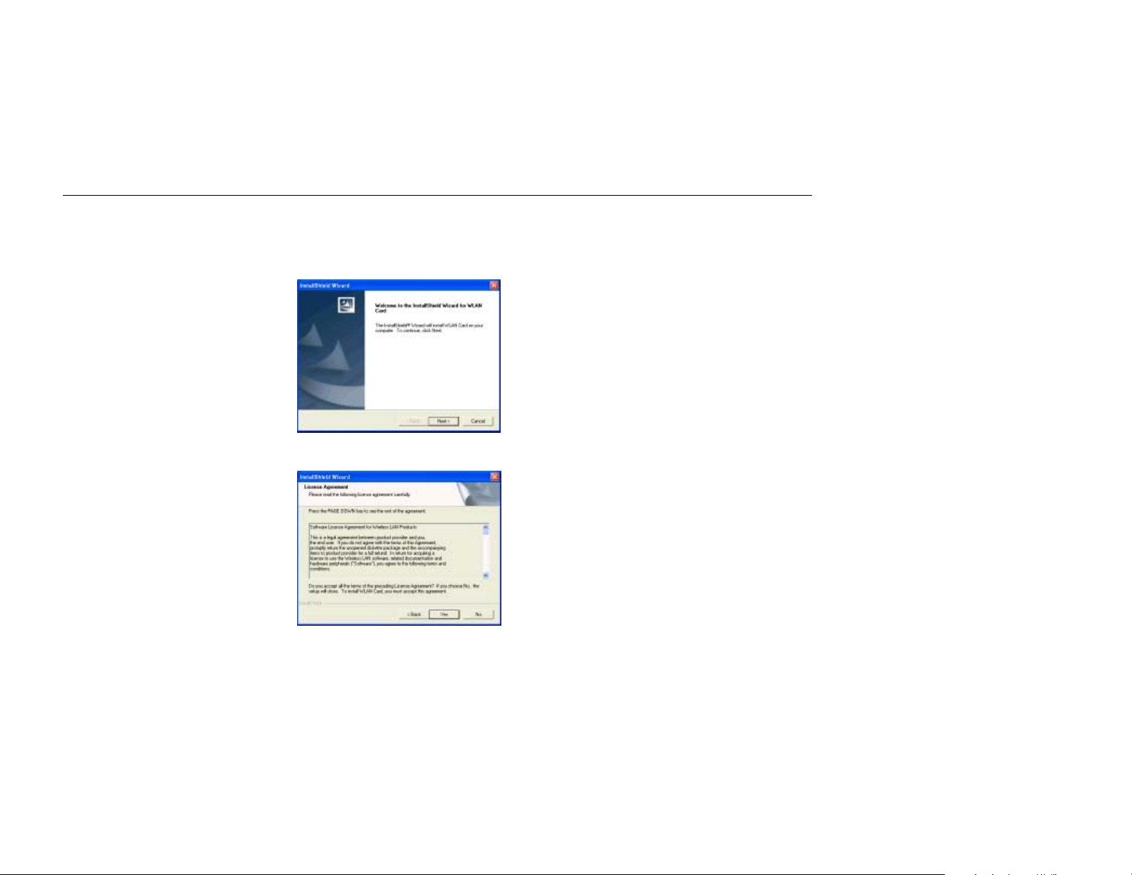
3. When the Welcome window pops up, click Next >.
4. When the License Agreement window appears, click Yes.
then double-click Setup.exe to launch the installer.
12
Page 21
Chapter 2—Installing the Aria extreme Card and Software
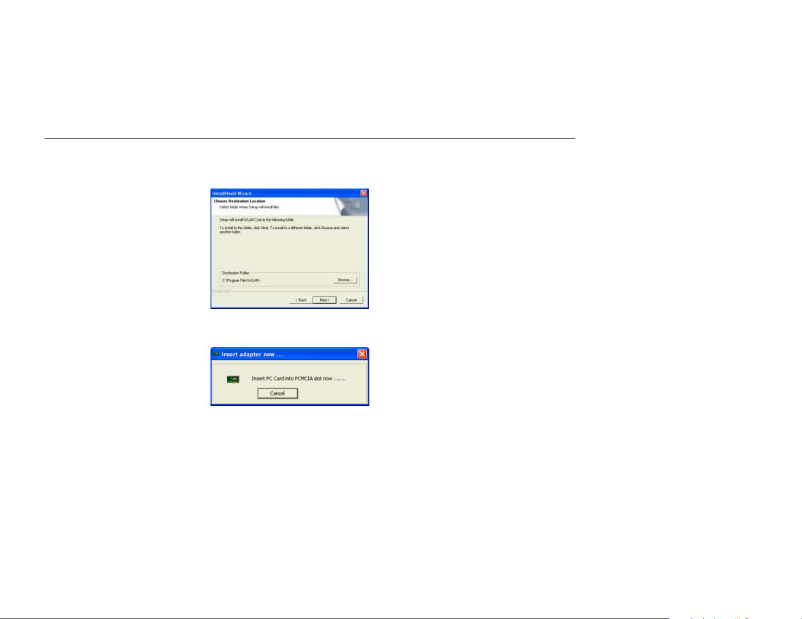
5. To install the software to the default destination folder, click Next. If you want to install
the software to a different folder, click Browse…, select another folder, and then click
Next >.
6. For the Aria extreme CardBus card only: When the Insert adapter now… window
appears, insert the Aria extreme card label up into the slot.
13
Page 22
54Mbps Wireless LAN Card User’s Manual
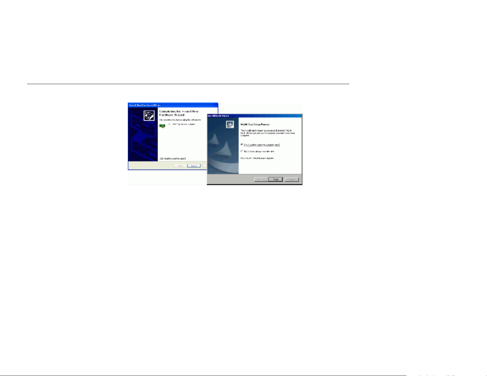
7. Click Finish when the following window appears; Windows may reboot.
14
Page 23

Chapter 2—Installing the Aria extreme Card and Software
General Guidelines for OS-Specific Situations
Depending on the Windows version running on your computer, different situations will occur
during or after the software installation. Follow the instructions on the next page to complete
the installation.
For Windows 98SE
When prompted for the Windows 98SE CD-ROM, click OK. Enter the path to your
original Windows 98SE files (CAB files), and then click OK.
If the original Windows 98SE files are not on your computer, you will need to insert your
Windows 98SE Installation CD.
When prompted to restart your computer, click Yes.
For Windows Me
If you are prompted to restart your PC, click Yes.
For Windows 2000
If the Digital Signature Not Found message appears, click Yes.
15
Page 24

54Mbps Wireless LAN Card User’s Manual
For Windows XP
If a Windows logo compatibility message appears, click Continue Anyway.
When a dialog box appears requesting a driver for the Aria extreme, select “Install the
If you are prompted to provide the driver, click OK, then click Browse to locate the
Once you are done with the software installation procedure, you will find the Wireless
Monitor icon located on the system tray; your Aria extreme is ready to use. Proceed to the
next chapter to learn how to configure your Aria extreme card’s settings.
Note: If you need to set up the TCP/IP address or the subnet mask, refer to “Appendix
C—Setting Up TCP/IP” for details.
software automatically” and click Next >.
directory you selected to install the Wireless LAN Utility (e.g., C:\Program
Files\WLAN\Driver\PCMCIA) and then click OK. Verify you’ve selected the same
path that you used to install the Wireless LAN Utility.
16
Page 25

Chapter 3—Using the Wireless LAN Utility
Once you have properly installed the driver software for the Aria extreme, you can configure
the card using the provided Wireless LAN Utility. The utility window has five tabs:
• Link Status - Displays general information about the connection and activity of your current
link. You can also enable or disable the card’s data transmission, and change power saving
settings for the card.
• Configuration - Displays the current network and operating mode settings. Configure your
wireless connection settings here.
• Encryption - Displays security settings. You can change settings for secure wireless
transmission.
• Site Monitor - Displays information for each available wireless network. You can select the
network to which you want to connect.
• About - Displays information about the Aria extreme card and the Wireless LAN utility.
Read the following pages for more complete descriptions of the features and settings you may
change from each tab.
17
Page 26
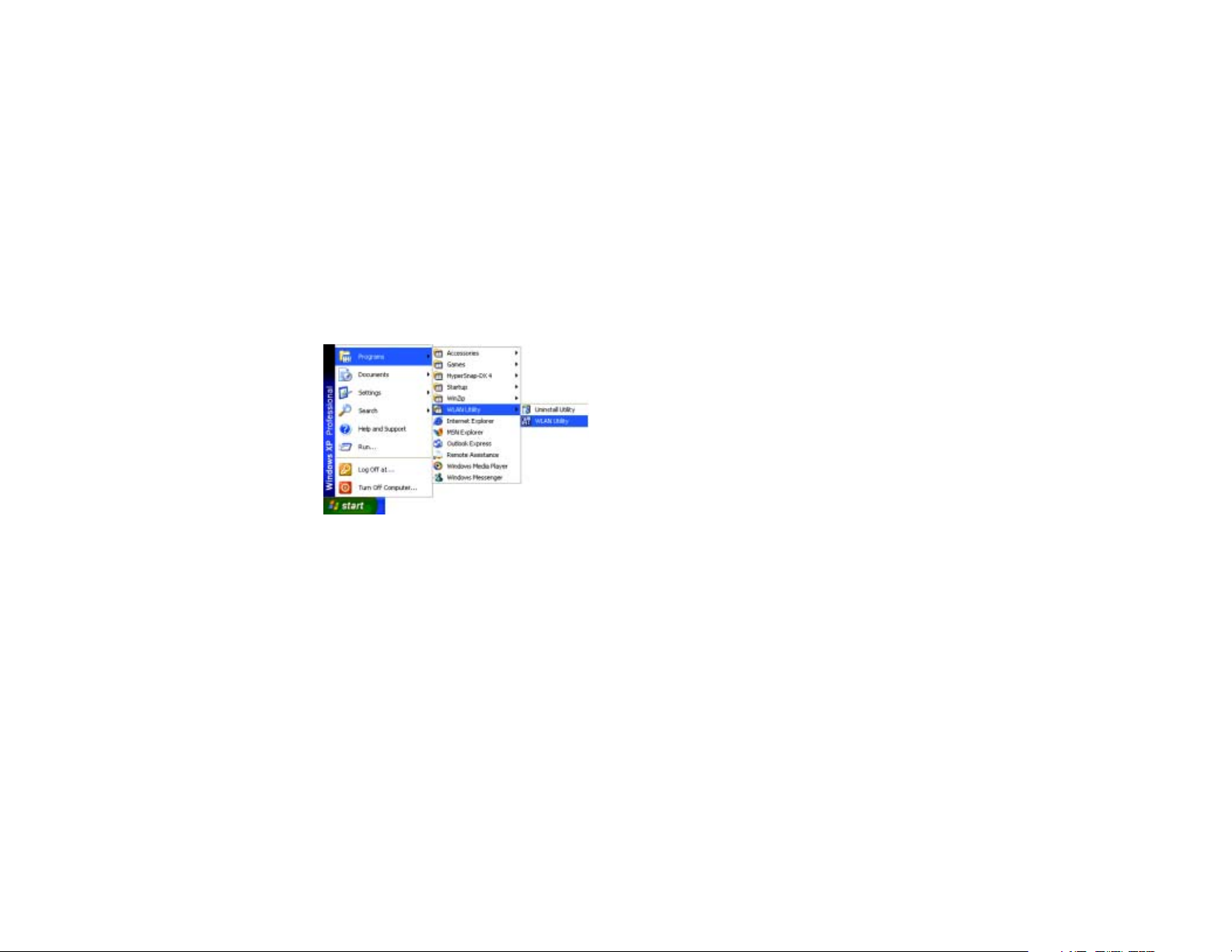
Launching the Wireless LAN Utility
To launch the Wireless LAN Utility, go to the Windows Start menu and select Programs >
WLAN Utility > WLAN Utility.
If you are using Windows XP, go to the next page. Otherwise, skip to page 22.
18
Page 27

Note About Using the Wireless LAN Utility Under Windows XP
Instead of using the Wireless LAN Utility for configuring your Aria extreme, you may also
configure it using the Wireless Zero Configuration Utility included with Windows XP. By
default, the Windows utility manages your Aria extreme. As a result, you may find that the
Configuration and Encryption tabs are not available in the Wireless LAN Utility.
Configuration and Encryption
tabs are not visible when Windows
XP overrides the Wireless LAN
Utility.
You can configure the Aria extreme using either the Wireless LAN Utility or Windows XP’s
utility.
19
Page 28

Using the Wireless LAN Utility
In order to use the Wireless LAN Utility for configuration purposes, you must follow these
steps to disable Windows XP’s Wireless Zero Configuration Utility:
1. Double-click the Wireless Zero Configuration Utility tray icon, click Properties (or
Advanced), and then select the Wireless Networks tab.
20
Wireless Zero Configuration
Utility icon
Sonnet s WLAN utility icon
2. Uncheck the “Use Windows to configure my wireless network settings” box on the
Wireless Connection Properties tab, and then click OK; the Wireless Networks tab in
the Wireless LAN Utility will be restored.
Page 29

Reverting to Windows XP’s Wireless Zero Configuration Utility
Double-click the Wireless Zero Configuration Utility icon (not the Wireless LAN Utility
icon), and then click Advanced (or Properties). Click the Wireless Networks tab, check the
“Use Windows to configure my wireless network settings” box, and then click OK.
21
Page 30

Link Status Tab
The Link Status tab displays general information about the connection and activity of your
current link. The following table describes the items found on the Link Status screen.
Screen Item Description
SSID Displays the name of the wireless network to which your computer
is currently connected.
Channel Displays the channel currently in use.
Tx Rate Displays the data transmission rate.
Link Quality Displays the measured link quality.
Signal Strength Displays the signal strength as a number (in dBm), and in a graph.
State Displays the current status, e.g. scanning or successful association.
In addition, there are three buttons on this tab:
Radio/Disable: Enables or disables the Aria extreme’s RF transmission.
Power Saving On: Reduces the Aria extreme CardBus card’s power consumption to
extend your laptop’s battery life.
22
Page 31

Reconnect: Reconnects your computer to its target wireless network.
Figure 3-1 Link Status Tab
23
Page 32

Configuration Tab
The Configuration tab displays the current network and operating mode settings for the Aria
extreme. The following table describes the items found on the Configuration screen.
Screen Item Description
Profile Name Name of your current settings.
Operating Mode Infrastructure or Ad-Hoc (peer-to-peer).
Network Name Specifies the name of the WLAN group in which you want to
participate.
For Ad-Hoc mode: A network name must be entered; the SSID for
all computers in a single Ad-Hoc network must be same.
For Infrastructure mode: If using the special SSID “ANY”(case
sensitive), your Wireless LAN Card will connect to the first
compatible and “open” AP with the best signal strength within the
connection range.
24
Page 33

Screen Item Description
Peer-to-Peer Channel Ad-Hoc mode ONLY. Specifies the selected channel for your
wireless network.
Note that the channels you are allowed to use are different according
to your geographic location. Make sure you select a legal channel
that is allowed in your regulatory domain.
US, Canada - Channels 1–11 (FCC)
Japan - Channels 1–14 (TELEC)
Europe - Channels 1–13 (ETSI)
Channels 10–13 for France
Transmit Rate Determines the data transmission speed. The default setting (Fully
Automatic) enables the Aria extreme to automatically adjust its data
transmission rate as the signal strength warrants. Note that the
available rates vary according to the supported rates of the
associated AP or wireless client:
For 802.11b AP or wireless client: 1, 2, 5.5 and 11 Mbps rates are
supported.
25
Page 34

Screen Item Description
For 802.11g AP or wireless client: 1, 2, 5.5, 6, 9,11, 12, 18, 24, 36,
48 and 54 Mbps rates are supported.
26
Page 35

Figure 3-2 Configuration Tab
Encryption Tab
In the Encryption tab, you may change settings to secure your network by using WEP (Wired
Equivalent Privacy). If encryption isn’t necessary, select Disable from the Encryption (WEP
security) drop-down menu. To enable WEP, follow the steps below:
1. Select 64 bits or 128 bits as the WEP key length from the Encryption (WEP security)
drop-down menu.
27
Page 36

2. From the Type list, select the required authentication type. (You should use the same
authentication method as used by your target wireless network.)
• Open Key: If your target wireless network uses Open Key, your authentication
request will be always accepted.
• Shared Key: If your target wireless network uses Shared Key, your Aria extreme
must be set to use correct WEP key to pass the authentication. If selected, your Aria
extreme must use identical WEP keys as the target wireless network.
3. Choose Alphanumeric or Hexadecimal as the key format, and then enter up to four
keys in the provide fields. When using Hexadecimal format, only digits 0–9 and letters
a–f, A–F are allowed. Make sure to enter the characters matching the required key
format and length as below:
ASCII characters Hexadecimal digits
64 bits 5 alphanumeric characters 10 hexadecimal digits
128 bits 13 alphanumeric characters 26 hexadecimal digits
28
Page 37

Figure 3-3 Encryption Tab
4. From the Use WEP Key list select which key you want to use to encrypt your
transmitting data.
5. After you have finished entering all the encryption settings, click Apply to activate the
changes.
29
Page 38

Note: When setting WEP keys for data encryption, all the wireless stations and/or Access
Points must use the same encryption key values. For example, if you use Key 1 on your
wireless adapter and a value is assigned, then the same value must be assigned to Key 1 for all
the users in a wireless network.
Site Monitor Tab
The Site Monitor tab displays general information for each available wireless network you
can access, and you can select the network to which you want to connect by double-clicking
the network’s name. In addition, you can use the Site Monitor feature to display the
communications quality between your computer and multiple APs or clients in its vicinity.
The Site Monitor enables you to conduct a site survey to:
Determine the overall wireless coverage of your wireless network.
Optimize placement of the Access Point(s), to provide seamless connectivity to mobile
stations.
Roam throughout the wireless network environment with your station to identify areas
that may not have adequate coverage, or that suffer from (wireless) interference by other
equipment such as microwave ovens, cordless phones, etc.
The list will update automatically to display all visible networks. Click Freeze checkbox to
freeze the list box so that you can read the information inside it; it will also stop the search for
available networks. To only display Ad-Hoc networks, select the Ad-Hoc networks only
checkbox.
30
Page 39

For each network, the following information will be displayed:
Field Description
Network Name Displays the name(s) of the wireless network(s).
Channel Lists the channel used by the AP or wireless station.
WEP Displays whether WEP is ON or OFF.
Signal Displays the signal strength in dBm.
Link Quality Measures the signal level.
Network Address The MAC address of the AP or wireless client.
AP band The frequency band used by the AP. You can identify whether the
AP or wireless client supports 802.11b & 11g or only 802.11b.
Infra. Describes the operating mode (Infrastructure or Ad-Hoc)
31
Page 40

32
Figure 3-5 Site Monitor Tab
Page 41

About Tab
The About tab displays information about the Aria extreme card and the Wireless LAN utility,
including the Utility, Driver and Firmware version details.
Figure 3-6 About Tab
33
Page 42

Page 43

Chapter 4—Using Wireless Tray Icon Functions
Viewing Signal Strength Information
Whenever you start Windows, you should be able to find the wireless monitor icon loaded in
the system tray, located near the clock on the task bar.
While connected to a network, you can place your cursor over the icon to view the pop-up text
that gives information about the wireless link and signal strength.
35
Page 44
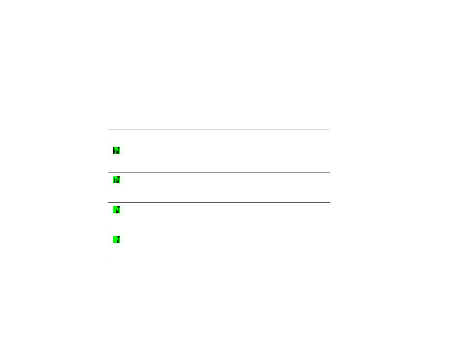
System Tray Icon Information
The wireless icon graphic changes to reflect the quality of your system’s wireless connection.
The table below describes the radio connection quality indicated by the icon, and lists
suggestions on how to improve the quality:
Graphic Radio Connection Quality
Very Good
Your Aria extreme card has an excellent radio connection with the network,
enabling excellent network communication at the highest transmit rate.
Good
Your Aria extreme card has a good radio connection with the network, enabling
normal network communication.
Low
The radio signal is low. Moving your computer closer to your target Access Point
or wireless station can result in better signal strength.
Poor
The radio signal is very weak. You should move your computer closer to your
target Access Point or wireless station for better signal strength.
36
Page 45

Graphic Radio Connection Quality
No signal.
You are out of range of the wireless network, or there may be network
configuration errors (such as your SSID or WEP encryption key doesn’t match
that of the target AP or wireless station).
Move your device closer to your target Access Point or wireless station, or verify
your SSID or WEP settings.
Radio if OFF (no transmission). You have manually disabled the RF signal.
Disconnected. There is no wireless connection available
37
Page 46

Other Functions
Right-click the wireless icon to display the menu shown below:
Each item on the context menu is described as below:
Radio ON/Radio OFF: Enables or disables the RF signal.
Link Status/Configuration/Encryption/Site Monitor/About: Opens the Wireless LAN
Utility.
HIDE: Closes the menu.
38
Exit: Shuts down the Wireless LAN Utility
Page 47

Chapter 5—Windows XP Wireless Zero Configuration Utility
Windows XP provides the built-in Wireless Zero Configuration utility for wireless
configuration and monitoring. You can choose to configure your wireless network via either
the included Wireless LAN Utility as described in previous section, or the Windows XP
Wireless Zero Configuration utility described in this chapter.
This section only provides the basic instructions for using the Windows XP wireless utility to
establish your wireless network. For more detailed information, please refer to Windows XP
online help.
Connecting to an Access Point or Wireless LAN Card
To connect to an existing Access Point or Wireless LAN card, perform the following steps:
1. Right-click the Wireless Connection icon on the system tray and select View Available
Wireless Networks from the context menu.
39
Page 48

Note: Depending on whether your wireless network is established, the context menu may
show different items.
2. When the Connect to Wireless Network window pops up, you will see all of the nearby
Access Points and Wireless LAN cards that are broadcasting. Select the wireless network
to which you want to connect.
Figure 5-1 Windows XP Configuration Utility-Connect to Wireless Network
3. If the selected Access Point or Wireless LAN Card has been set up using a WEP key,
you must enter the same WEP key in the Network key field. Otherwise, leave it blank.
40
Page 49

4. Click Connect, and then you will join the target network; this dialog window will
disappear. When your wireless connection is established, the connection icon appears as
shown below:
Note: If the wireless connection can’t be established, double-click the connection icon and
then click Properties. Go to Authentication tab first to make sure that you have entered the
correct authentication type for the Aria extreme. For more information, refer to
“Authentication” on page 47.
41
Page 50
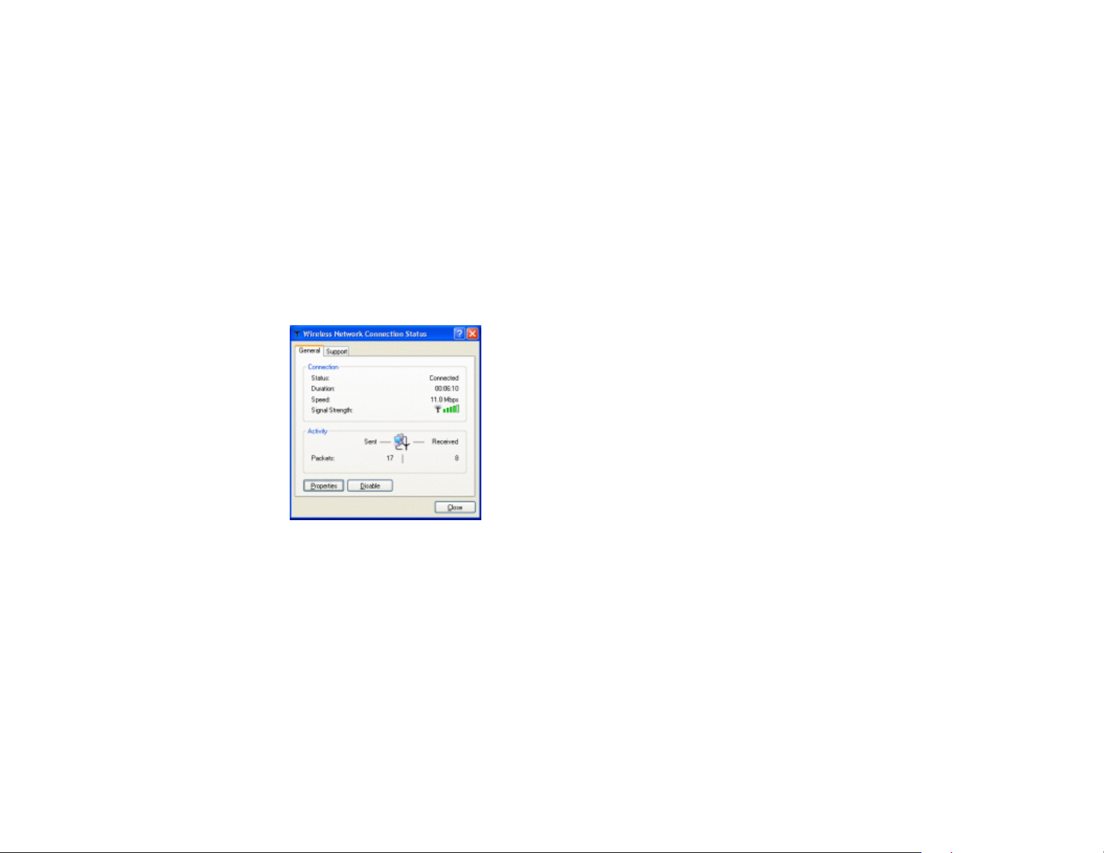
Viewing the Wireless Connection Status
After successfully connecting to a wireless network, double-click the wireless connection icon
in the system tray again; the Wireless Network Connection Status window will open. You
can view general configuration information for the Aria extreme, such as Status, Duration,
Speed, Signal Strength, etc.
Figure 5-2 Windows XP- Connection Status
42
Page 51

Configuring the Wireless Connection Properties
To configure the wireless connection properties, open the Wireless Network Connection
Status window as described above, and then click the Properties button; the Wireless
Network Connection Properties window will open. You can configure the Aria extreme
card’s more advanced settings. The following describes the contents of each of the properties
window’s tabs to enable you to configure the Aria extreme to suit your needs.
General
With this tab selected, you can specify the network connection method to be used with your
Aria extreme. The network policy depends on your wireless network. For TCP/IP protocol,
you should configure its properties as instructed by your network administrator. For more
information on TCP/IP setting, please refer to “Appendix C—Setting Up TCP/IP” on page 65.
Figure 5-3 Windows XP Connection Properties -General
43
Page 52

Wireless Networks
This tab contains two sections: Available networks and Preferred networks described as
below.
Under Available networks section, you can also see all the available nearby Access Points
and Wireless LAN Cards. Click Refresh to update the list of Access Points and Wireless LAN
Cards.
44
Figure 5-4 Windows XP Connection Properties-Wireless Networks
Page 53
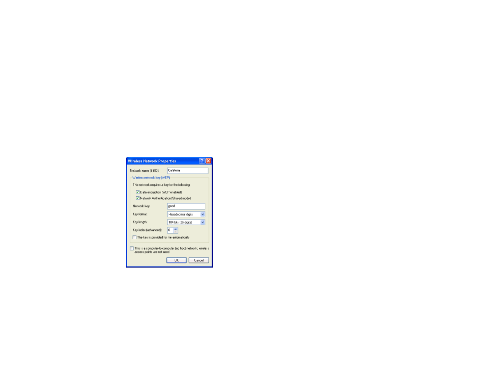
Under Preferred networks section, you can add any wireless networks to which you wish to
connect. To do this, just click Add to add more Access Points or Wireless LAN Cards to the
list.
After you click the Add button, the Wireless Network Properties window pops up. Type
your network name (SSID) and, if needed, the wireless network WEP settings. If the Access
Point or Wireless LAN Card that you want to connect to has been set with WEP key, you must
type the same WEP key as the Access Point’s or Wireless LAN Card’s.
Figure 5-5 Windows XP-Add Preferred Networks
45
Page 54

After you add several profiles into Preferred networks, you can change the order in which
connection attempts to preferred networks are made. Just select the target wireless network
and click Move up or Move down to move it to a desired position.
Limit Access to Specific Wireless Network Types
If you only want to access certain wireless network types, click the Advanced button on the
Wireless Networks tab to open the Advanced window. You can choose to connect to the
following networks:
• Any available network (access point preferred)
• Access point (infrastructure)
• Computer-to-computer (Peer-to-Peer Group)
The default network type is Any available network (access point preferred). In this network
type, your device will connect to any nearby available Access Points or Wireless LAN Cards,
but Access Point connection attempts receive higher priority.
46
Page 55

Once you finish changing the Advanced settings, your Aria extreme will then connect to your
desired network, and the connected network will be listed under Available networks.
Figure 5-6 Windows XP Configuration Utility-Set up a Network to Aceess
Authentication
With this tab selected, you can configure your Aria extreme card’s authentication settings. Be
sure to disable Enable network access control using IEEE802.1X to ensure successful
connection between the Aria extreme and Access Points or other wireless LAN Cards. You
must disable this function. Otherwise, problems may occur during connection. For other
settings, we recommend you keep the default settings to minimize the problems during
connection.
47
Page 56

48
Make sure to disable Enable
network access control
using IEEE 802.1X.
Figure 5-7 Windows XP Connection Properties – Authentication
Page 57

Chapter 6—Uninstalling the Aria extreme
Should you need to uninstall the Aria extreme and its application software for any reason, you
should uninstall the associated software first, and then remove the hardware from your
computer. Please proceed as follows.
Uninstalling the Wireless LAN Card Software
Note: Before uninstalling the Wireless LAN Card software, please disable the utility by rightclicking the utility tray icon and select Exit from the context menu. The icon will disappear to
indicate that the utility is not in operation.
49
Page 58

1. Close all programs that are currently running.
2. Click the Windows Start button, point to Programs > WLAN Utility > Uninstall
Utility.
3. Click OK to proceed with the software uninstall procedure.
50
Page 59

4. Click Finish to complete the software uninstallation. Depending on which Windows
version is running, your computer may reboot.
51
Page 60

Removing the Aria extreme Card
To permanently remove the Aria extreme card from your computer, make sure that you have
uninstalled the software before you remove the hardware. If you have an Aria extreme PCI
card, follow the procedure described in your computer’s owner’s guide.
The Aria extreme CardBus card complies with the PCMCIA standard that allows devices to be
inserted into and removed from the computer’s PCMCIA slot when the computer is powered
on. To remove the Aria extreme, it is recommended that you follow the standard Windows
procedure for disconnecting a PCMCIA device from your computer. The following steps
describe a Windows 98 environment:
1. On the system tray, right-click the PCMCIA icon, and then click Adjust PC Card
Properties.
2. Select the Wireless LAN Card that you want to remove, click Stop.
3. When the message appears that tells you it is safe to remove device, click OK and remove
the Wireless LAN Card from the computer.
4. Click OK to exit the PC Card (PCMCIA) Properties window.
52
Page 61

Chapter 7—Troubleshooting
Verify the Aria extreme is functioning properly
After installation you can verify whether the Aria extreme is properly installed and
functioning by followings these steps:
1. Launch the Device Manager as below:
• For Windows 98/Me: Under Control Panel, click System > Device Manager.
• For Windows 2000/XP: Under Control Panel, click System > Hardware > Device
Manager.
2. In the Device Manager window, double-click Network adapters to display your Aria
extreme.
3. If there is no exclamation mark next to the Aria extreme, it is working properly.
Otherwise, you will need to remove and reinstall the wireless adapter.
53
Page 62

Cannot Install under Windows 2000
When attempting to install the software under Windows 2000, the error message “1608:
Unable to create InstallDriver instance” is displayed, and the program stopped installing.
This error occurs when the Microsoft Network Client is not installed under Windows 2000.
To install this network component:
1. Go to Control Panel and double-click the Network and Dial-up Connections icon.
Right-click on the Local Area Connection, then select Properties.
2. Click Install > Client > Add > Client for Microsoft Networks > OK.
3. The Microsoft Network Client is now installed. Manually restart your computer to
enable the changes.
4. Try to install the software again, following the steps in this manual.
Radio Interference
You may be able to eliminate or reduce interference by trying the following:
• Reseat the Aria extreme card in its slot.
• Increase the distance between your computer and the device causing the radio
interference.
54
Page 63

• Plug your computer into an electrical outlet on a different branch circuit than that
used by the affecting device.
• Consult your dealer or an experienced radio technician for help.
• Keep your away from microwave ovens and large metal objects.
Card Not Detected
If Windows does not detect the Aria extreme, try the following:
• Make sure the Aria extreme is properly inserted in the computer.
• For the Aria extreme CardBus card, make sure you are using a 32-bit CardBus
expansion slot, and that the slot is working.
• Contact your dealer for additional testing if there is a hardware problem with the
Aria extreme.
Cannot Connect to Another Wireless LAN Card
If you cannot make a connection to another Wireless LAN Card from your computer, it could
be due to one of the following reasons:
• Incorrect network name (SSID). Make sure the SSID is the same for all computers
that have a Wireless LAN Card.
• Your computer is not recognizing changed settings. Restart your computer.
55
Page 64

• If in Ad-Hoc mode, make sure the Log on to Windows NT domain check box is
• Incorrect IP Address or Subnet Mask settings. Check these in the TCP/IP
• Make sure you are not trying to connect to an 802.11a wireless adapter. 802.11a
Poor Link Quality
If the Link Quality display stays in the poor range, it could be due to one of the following
reasons:
• For Aria extreme PCI cards, verify the antenna is screwed in securely; try moving
• Radio/object interference. To minimize this problem, move the devices within the
• Distance between the Aria extreme and the target Access Point or wireless client is
NOT selected in the Client for Microsoft Networks Properties dialog box in the
Network Configuration tab.
Properties dialog box in the Network Configuration tab.
and 802.11b/g standards are not interoperable.
the antenna to a different position.
line of sight.
too great. Decrease the distance between devices.
56
Page 65

Cannot Connect to Access Point
If you cannot make a connection to an Access Point, it could be due to one of the following
reasons:
• Physical connection problems at the Access Point. Check the AP and verify all the
connectors are plugged or screwed in securely.
• Incorrect network name (SSID). Make sure the SSID used is the same for both the
Aria extreme and the Access Point.
• Security settings different. Make sure the security settings are the same for both the
Aria extreme and the Access Point.
• Operation mode not configured properly. Make sure the Aria extreme is configured
to allow Infrastructure connections.
• Make sure you are not trying to connect to an 802.11a Access Point. 802.11a and
802.11b/g standards are not interoperable.
• The Access Point has reached its maximum number of supported clients.
• MAC address access control is enabled on the Access Point. If this is the case,
make sure your Aria extreme card’s MAC address is on the “Allow Access” list.
57
Page 66

Page 67

Appendix A—Limited Warranty
Wireless LAN Hardware
Sonnet Technologies, Inc. warrants that its product(s) shall be free from defects in materials
and workmanship for a period of three years following the date of original purchase. Sonnet’s
liability under this warranty shall be limited, at its option, to repairing or replacing product(s)
shown to be defective either in materials or workmanship. The sole and exclusive remedy
under this warranty shall be such repair or replacement.
A claim of defective materials or workmanship in product(s) shall be allowed only when it is
submitted to Sonnet within the warranty period. No claim shall be allowed in respect to
product(s) which have been altered, neglected, damaged or stored in any manner which
adversely affects them. No product(s) shall be returned to Sonnet for any reason without a
return authorization from Sonnet. You bear the responsibility for shipping product(s) to
Sonnet within 30 days of authorization and paying for associated shipping and insurance costs.
Sonnet will pay the cost to ship repaired or replaced product(s) back to you.
This warranty shall also apply to product(s) that replace defective product(s) but only for the
original warranty period. The warranty period shall not be extended by reason of defect, or
59
Page 68

any period of time during which the product(s) are not available to you because of defects,
without the express written consent of Sonnet.
EXCEPT FOR THE EXPRESS WARRANTY AGAINST DEFECTS IN MATERIALS AND
WORKMANSHIP CONTAINED HEREIN, SONNET MAKES NO WARRANTY OF
ANY KIND WHATSOEVER, EXPRESS OR IMPLIED, AND ALL WARRANTIES OF
MERCHANTABILITY AND FITNESS FOR A PARTICULAR PURPOSE ARE HEREBY
DISCLAIMED BY SONNET. Without limitation of the foregoing, Sonnet expressly disclaims
any liability whatsoever for any damages incurred, directly or indirectly, in connection with its
product(s), including without limitation, loss of profits and special, incidental or consequential
damages, whether caused by Sonnet’s negligence or otherwise.
60
Page 69

Appendix B—Regulatory Compliance
FCC Part 15 Declaration of Conformity (DoC)
The following equipment:
Product Name: Aria extreme
is herewith confirmed to comply with the requirements of FCC Part 15 rules. The operation is
subject to the following two conditions:
1. This device may not cause harmful interference, and
2. This device must accept any interference received, including interference that may cause
undesired operation.
61
Page 70

FCC Rules and Regulations - Part 15
Warning: This device has been tested and found to comply with the limits for a Class B
digital device pursuant to Part 15 of the Federal Communications Commissions Rules and
Regulation. These limits are designed to provide reasonable protection against harmful
interference when the equipment is operated in a commercial environment. This equipment
generates, uses, and can radiate radio frequency energy and, if not installed and used in
accordance with the instruction manual, may cause harmful interference to radio
communications.
However, there is no guarantee that interference will not occur in a particular installation. If
this equipment does cause harmful interference to radio or television reception, which can be
determined by turning the equipment off and on, the user is encouraged to try and correct the
interference by one or more of the following measures:
• Relocate your WLAN equipped computer.
• Increase the separation between the WLAN equipped computer and other
electronics.
• Connect the WLAN equipped computer into an outlet on a circuit different from
that of other electronics.
• Consult the dealer or an experienced radio/TV technician for help.
62
Page 71

FCC Radiation Exposure Statement
This equipment complies with FCC radiation exposure limits set forth for an uncontrolled
environment. This equipment should be installed and operated with minimum distance of
20cm between the radiator & your body.
63
Page 72

Page 73

Appendix C—Setting Up TCP/IP
This section contains instructions for configuring the TCP/IP protocol for the Aria extreme.
The IP address policy depends on your wireless network; you should configure the TCP/IP
protocol as instructed by your network administrator.
For Windows 98/ME
1. Double-click the Network icon on the Control Panel.
2. Click the Configuration tab in the Network dialog box.
65
Page 74

3. In the network components list, select the TCP/IP protocol for the Aria extreme, e.g.,
TCP/IP ->Broadcom 802.11g Network Adapter and then click Properties.
4. With the IP Address tab selected, choose one of the methods as required:
Option A: Click Specify an IP address.
In the IP Address box, enter a valid four-component IP address, either a public or
private one as required.
In the Subnet Mask box, enter a valid four-component IP address.
Then select the Gateway tab and enter your gateway information.
Option B: Select Obtain an IP address automatically.
An IP address will be automatically assigned to your computer.
66
Page 75

5. Click OK to return to the Network dialog box and click OK again to finish the
configuration procedure. If your TCP/IP properties have been modified, you will be
prompted to restart your computer. Click Yes to have new settings take effect.
67
Page 76

For Windows 2000/XP
1. Double-click Network Dial-up Connections (Windows 2000) or Network Connections
(Windows XP) on Control Panel, then Network Connections.
2. Right-click the Broadcom 802.11g Network Adapter icon and click Properties.
68
Page 77

3. With the General tab selected, highlight Internet Protocol (TCP/IP) and then click
Properties.
Option A: Use a fixed IP address.
Enable the Use the following IP Address option. Enter the IP address, Subnet Mask
and Default gateway. Then click OK.
Option B: Use a dynamic IP address
Select Obtain an IP address automatically.
4. Close the Local Area Connection Properties window. For Windows 2000, if prompted,
click Yes to restart your computer.
69
Page 78

Page 79

Appendix D Specifications
Host Interfaces CardBus, PCI Spec. 2.2
Form factors
Chipset
Operation Voltage
Network Standards
Modulation Techniques
Modulation Technology
Data Rate
Network Architectures
Type III B/32bit CardBus, PCI
Broadcom BCM 4306 & BCM 2050
3.3VDC
IEEE 802.11b (Wi-Fi™) standard and IEEE 802.11g standard (54G)
DBPSK, DQPSK, CCK, 16QAM, 64QAM
OFDM, DSSS
802.11b – 11 Mbps maximum, Auto-ranging 1, 2, 5.5, and 11 Mbps
802.11g – 54 Mbps maximum, Auto-ranging 6, 9, 12, 18, 24, 36, 48, and 54 Mbps
Infrastructure and Ad-Hoc
71
Page 80

Operating Frequencies
Operating Channels
2.4–2.497 GHz
802.11b - North America: 11, Japan: 14, Europe (ETSI): 13
802.11g - North America, Japan, Europe (ETSI): 13
72
RF Output Power
Receiver sensitivity
(PER < 10%)
Antenna Type
Indoor Coverage Area (Typical)
Power Consumption
Security
15 dBm maximum output power (14 dBm nominal ± 1 dBm over operating
temperature
-80dBm @ 6Mbps
Hardware diversity support: transmit and receive on Main and Auxiliary antenna
connectors.
802.11b: Up to 60 M at 11 Mbps, up to 125 M at 1 Mbps
802.11g: Up to 20 M at 54 Mbps, up to 75 M at 18 Mbps
Tx peak: 550 ma @ 3.3VDC; Rx peak: 350 ma @ 3.3VDC;
Idle: 225mA @ 3.3VDC
Hardware 64/128-bit WEP engine; WEP weak-key avoidance, TKIP, hardware
AES engine supporting CCM and OCB, 802.1x, SSN
Page 81

Delay Tolerance
802.11b: Multipath R.M.S Delay Spread @ 1% FER: 11 Mbps > 250 nsec; 5.5
Mbps > 300 nsec
Client Utility
Software Support
LED Indicators
Switch
Temperatures
Humidity (non-condensing)
Certifications
Automatic location profile, site monitor, current link status, and diagnostics
Microsoft WHQL certified for Windows XP, 2000, and ME. Linux and VxWorks
embedded drivers.
WLAN Activity Monitor, WLAN Radio Status Indicators
M a n u a l r a d i o o n / o f f i n s o f t w a r e d i s a b l e s t r a n s m i t a n d r e c e i v e t o
c o m p l y w i t h a v i a t i o n i n - f l i g h t r e s t r i c t i o n s
Operating: 0˚–158˚ F (0˚–70˚ C)
Storage: -20˚–194˚ F (-4˚–90˚ C)
5 to 95%
FCC Part 15
CE
TELEC
JATE
* Specifications are subject to change with notice.
73
Page 82

Glossary
802.11 802.11 refers to a family of specifications developed by the IEEE for wireless LAN
technology. 802.11 specifies an over-the-air interface between a wireless client and a
base station or between two wireless clients.
Access Point An internetworking device that seamlessly connects wired and wireless networks.
Access Points combined with a distributed system support the creation of multiple radio
cells that enable roaming throughout a facility.
74
Ad-Hoc
(Peer-to-Peer)
Default Gateway The address used to forward all traffic that is not addressed to a station within a local
An 802.11 networking framework in which devices or stations communicate directly
with each other, without the use of an Access Point (AP). Ad-hoc mode is useful for
establishing a network where wireless infrastructure does not exist or where wired
network services are not required. Ad-hoc mode is also referred to as peer-to-peer mode
or an Independent Basic Service Set (IBSS).
Bit A bit (short for binary digit) is the smallest unit of data in a computer. A bit has a single
binary, either 0 or 1.
BSS Basic Service Set. In a network where an AP is connected to wired network and is
associates with a set of wireless stations, it is referred to as a BSS.
ESS Extended Service Set. An Extended Service Set (ESS) is a set of two or more BSSs that
form a single network. It’s basically a roaming wireless network.
subnet.
Page 83

Encryption The translation of data into a secret code. Encryption is the most effective way to
achieve data security. To read an encrypted file, you must have access to a secret key or
password that enables you to decrypt it.
Ethernet The most widely used medium access method, which is defined by the IEEE 802.3
standard. Ethernet is normally a shared media LAN; i.e., all the devices on the network
segment share total bandwidth. Ethernet networks operate at 10 Mbps, 100 Mbps, or
1000 Mbps using CSMA/CD to run over 10BaseT cables.
Gateway A network component that interconnects networks with different, incompatible
communications protocols.
IEEE Abbreviation of Institute of Electrical and Electronics Engineers, pronounced I-triple-E.
Founded in 1884 as the AIEE, the IEEE was formed in 1963 when AIEE merged with
IRE. IEEE is an organization composed of engineers, scientists, and students. The IEEE
is best known for developing standards for the computer and electronics industry.
Infrastructure An 802.11 networking framework in which devices communicate with each other by
first going through an Access Point (AP). In Infrastructure mode, wireless devices can
communicate with each other or can communicate with a wired network.
IP Internet Protocol. The standard protocol within TCP/IP that defines the basic unit of
information passed across an Internet connection by breaking down data messages into
packets, routing and transporting the packets over network connections, then
reassembling the packets at their destination. IP corresponds to the network layer in the
ISO/OSI model.
IP Address An IP Address is a 32-bit number that identifies each sender or receiver of information
sent across the Internet. An IP address has two parts: the identifier of a particular
75
Page 84

network on the Internet and an identifier of the particular device (which can be a server
or a workstation) within that network.
LAN Local Area Network. A communication network that serves users within a defined
geographical area. The benefits include the sharing of Internet access, files, and
equipment, such as printers and storage devices. Special network cabling (such as
10BaseT) is often used to connect the PCs together.
MAC Address The MAC (Media Access Control) Address is a 12 digit Hexadecimal number that
uniquely identify your network adapter on the network.
Media The materials used to connect network devices, such as twisted-pair wire, coaxial cables,
or fiber optic cables. Some networks do not use physical connecting media;
communications are achieved via radio waves instead.
Mbps Stands for millions of bits per second or megabits per second and is a measurement for
data transmission
Protocol The rules and encoding specifications for sending data.
RF Radio Frequency, any frequency within the electromagnetic spectrum associated with
radio wave propagation. When an RF current is supplied to an antenna, an
electromagnetic field is created that then is able to propagate through space.
Roaming In an Infrastructure mode wireless network, roaming refers to the ability to move from
one AP coverage area to another without interruption in service or loss in connectivity.
SSID Service Set Identifier, up to 32-character unique identifier attached to the header of
packets sent over a WLAN that acts as a password when a mobile device tries to connect
to the BSS. The SSID differentiates one WLAN from another; so all access points and
76
Page 85

all devices attempting to connect to a specific WLAN must use the same SSID. A device
will not be permitted to join the BSS unless it can provide the unique SSID. An SSID is
also referred to as a Network Name because essentially it is a name that identifies a
wireless network
Subnet Mask A value that defines whether your computer communicates only within your LAN or
communicates outside of your LAN, where it is routed out to the rest of the Internet. A
Subnet Mask that has the same first three components (for example, 255.255.255.0) is
the routing pattern for a Class C address.
TCP Transmission Control Protocol. The standard transport level protocol that provides the
full duplex, stream service on which many applications’ protocols depend. TCP allows a
process on one machine to send a stream of data to a process on another. Software
implementing TCP usually resides in the operating system and uses the IP to transmit
information across the network.
Topology The geometric arrangement of devices on a network. For example, devices can be
arranged in a ring, bus or star.
77
Page 86

WEP Wired Equivalent Privacy, a security protocol for wireless local area networks defined in
the 802.11b standard. WEP is designed to provide the same level of security as that of a
wired LAN. LANs are more secure than WLANs because LANs are somewhat
physically protected by their structure, having some or all part of the network inside a
building protected from unauthorized access. WLANs, which are over radio waves, do
not have the same physical structure and therefore are more vulnerable to tampering.
WEP aims to provide security by encrypting data over radio waves so that it is protected
as it is transmitted from one end point to another.
WLAN Wireless Local Area Network. A group of computers and devices that communicates
with each other wirelessly.
78
 Loading...