

SONIX SNR008 Datasheet
SNR008
8M-bit Mask ROM
======== Contents ========
1. INTRODUCTION............................................................................................................... 3
2. FEATURES ....................................................................................................................... 3
3. PIN ASSIGNMENTS ......................................................................................................... 3
4. Memory mapping for AD Bus Interface......................................................................... 4
5. ABSOLUTE MAXIMUM RATINGS................................................................................... 5
6. ELECTRICAL CHARACTERISTICS ................................................................................ 5
7. Application circuit ........................................................................................................... 6
7.1 AD Bus Interface (with SNC710) ..................................................................................6
7.2 Standard ROM interface (with SNL310) ....................................................................... 7
8. BONDING PAD................................................................................................................. 8
Ver. 1.3
August 29, 2003
1

SNR008
8M-bit Mask ROM
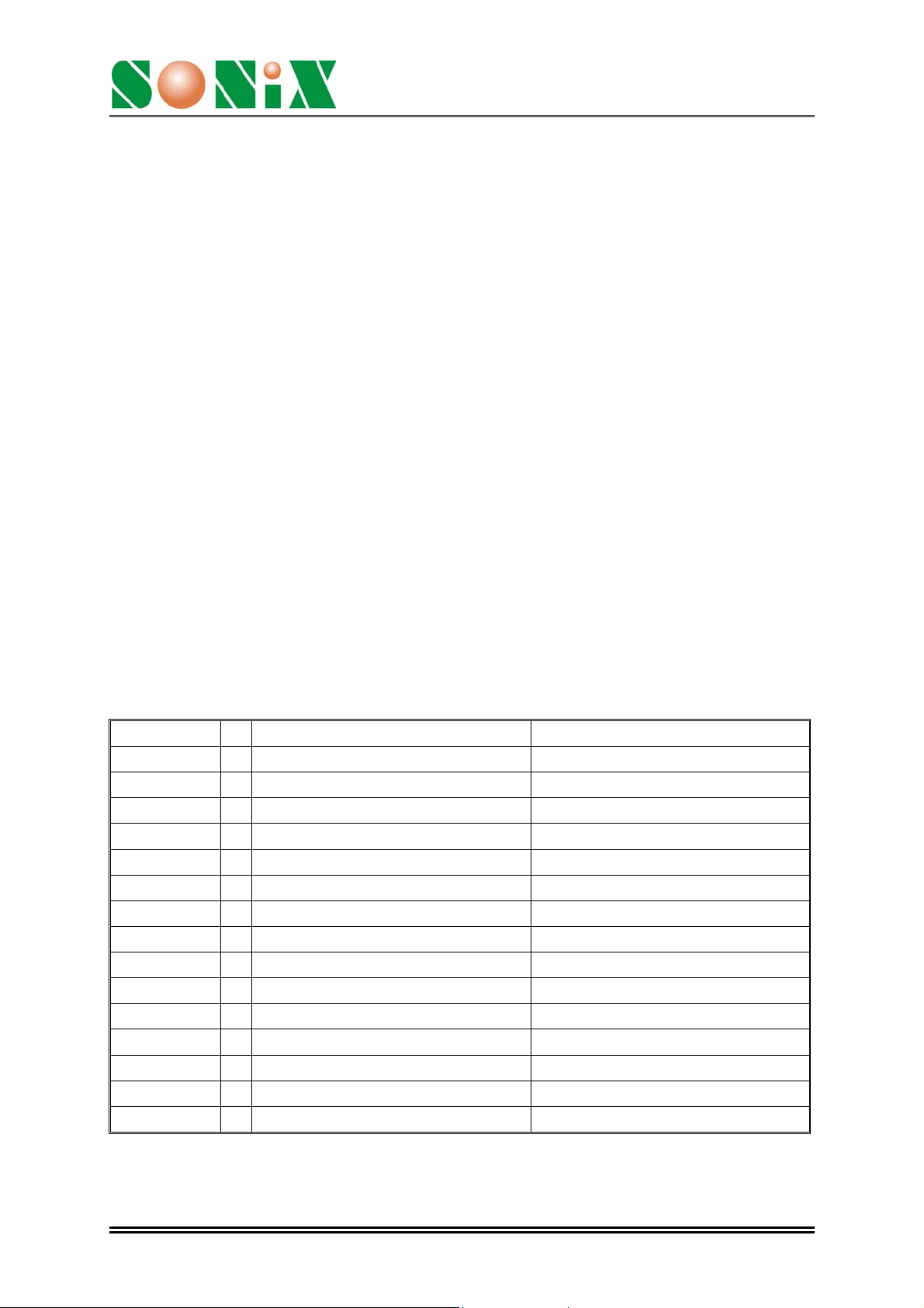
AMENDENT HISTORY
Version Date Description
Ver 1.0 March 11, 2003 V1.0 first issue
Ver 1.1 April 18, 2003 Modify the pin assignment table
Add bonding pad information & application circuit
Ver 1.2 April 21, 2003 Modify application circuit & bonding pad information
Ver 1.3 August 29, 2003 Modify operation current from typ.4mA -> MAX. 4mA
Modify access time Max = 200ns in
Electrical Characteristic
Ver. 1.3
August 29, 2003
2
SNR008
8M-bit Mask ROM
1. INTRODUCTION
The SNR008 is a signal power, 8M-bit, read only memory. It is organized as 1M bytes,
operates for single 3V power supply, support static standby mode. The SNR008
embedded two different interfaces, one is a standard 8-bit interface bus which
compatible with SNL310, another one is a special 8-bit AD (address/data) bus which
compatible with SNC710.
SNR008 offers automatic power-down, with power-down controlled by the chip enable
“CE\”. When chip enable goes to high, SNR008 will entry power-down mode in order to
save the power consumption.
2. FEATURES
Power supply: 2.4V ~ 3.6V ♦
♦
Memory Size: 8M-bit
♦
Totally static operation
♦
Embedded a standard 8-bit bus interface compatible with SNL310 or a 8-bit AD
(address/data) bus interface compatible with SNC710
♦
Access time: 200ns @3V
3. PIN ASSIGNMENTS
Symbol I/O Standard ROM interface AD Bus interface
TYPE I 1: Standard ROM type 0: AD Bus interface
A[8..19] I Standard ROM Address [8..19] NC
A[7] I Standard ROM Address A7 TESTM
A[6] I Standard ROM Address A6 Bank Select 4
A[5] I Standard ROM Address A5 Bank Select 3
A[4] I Standard ROM Address A4 Bank Select 2
A[3] I Standard ROM Address A3 Bank Select 1
A[2] I Standard ROM Address A2 Bank Select 0
A[1] I Standard ROM Address A1 ALECLK
A[0] I Standard ROM Address A0 READY
D[0..7] I/O Standard ROM Data [0..7] Address/Data bus [0..7]
CEB I Standard ROM Chip Enable Chip Enable
OEB I Standard ROM Output Enable NC
VDD P 3.3volt Positive Power supply 3.3volt Positive Power supply
GND P Ground Ground
Ver. 1.3
August 29, 2003
3
 Loading...