

Page 1
MD111124-01
Full-motion Wall Mount
AWM1701
Page 2
NOTE: Read the entire instruction manual before you start installation and assembly.
WARNING
• Do not begin the installation until you have read and understood the instructions
and warnings contained in this installation sheet. If you have any questions
regarding any of the instruction or warning, please contact your local distributor.
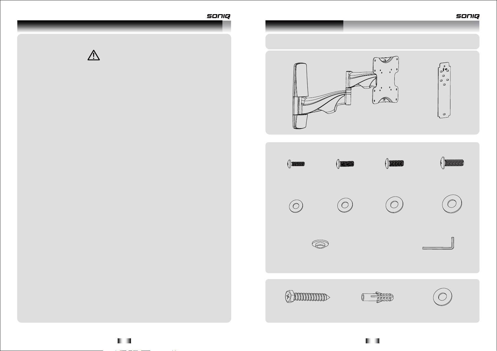
Component Checklist
IMPORTANT: Ensure that you have received all parts according to the component checklist prior to installing. If
any parts are missing or faulty, telephone your local distributor for a replacement.
• This mounting bracket was designed to be installed and utilized
ONLY as
specified in this manual. Improper installation of this product may cause damage
or serious injury.
• This product should only be installed by someone of good mechanical ability,
with basic building experiences and fully understanding of this manual.
• Make sure that the supporting surface will safely
support the combined load of
the equipment and all attached hardware and components.
• Never exceed the maximum load capacity.
• If mounting to wood wall studs, make sure that mounting screws are anchored
into the center of the studs. Use of a stud finder is highly recommended.
• Always use an assistant or mechanical lifting equipment to safely lift and position
equipment.
• Tighten screws firmly, but do not over tighten. Over tightening can damage the
items, greatly reducing their holding power.
• This product intended for indoor use only. Using this product outdoors could
lead to
product failure and personal injury.
Package M
M4x14 (x4)
D4 washer
Package W
M-A
(x4)
M-E
ø13.5xø5.5x3.2 (x4)
M-I
M5x14 (x4)
M-B
D(x4)5 washer
M-F
M6x14 (x4)
M-C
D6 (x4)washer
M-G
wall template (x1)
M8x15 (x4)
M-D
D8 (x4)washer
M-H
4mm allen key (x1)
M-J
ST6.3x55 (x5)
W-A
-1- -2 -
concrete anchor (x5)
W-B
D6 ø6.5xø24 washer (x5)
W-C
Page 3

1. Removing the Decorative Covers
3a. Wo o d Stud Wall Mounting:
2. Disassemble VESA Plate from Wall Mount
W-C
W-A
55mm/2.2"
√
ø 4.5mm
ø 3/16"
1
2
3
Drill pilot holes
XX
Loosen the upper thumbscrew,
Remove the lower thumbscrew
WARNING
• Make sure that mounting screws are anchored into the center of the studs. Use of a stud finder
is highly recommended.
• Installers are responsible to provide hardware for other types of mounting situations.
• Installer must verify that the supporting surface will safely support the combined load of
Remove VESA plate
-3 - -4 -
equipment and all attached hardware and components.
Screw the wall
mount onto
the wall
with the up arrow of the plate upward
the
Page 4

3b. Solid Brick and Concrete Block Mounting:
4. Installing Decorative Covers
W-B
W-C
W-A
60mm/2.4"
√
ø 10mm
ø 3/8"
1
2
Drill pilot holes
XX
5. Installing VESA Plate
Screw the wall
mount onto
the wall
with the up arrow of the plate upward
WARNING
• When installing wall mounts on cinder block, verify the actual concrete thickness is at least
1-3/8" (35mm) for using the concrete anchors. Do not drill into mortar joints! Be sure to
mount in a solid part of the block, generally 1" (25mm) minimum from the side of the
It is suggested electric drill on slow setting is used to drill the hole instead of a hammer drill
to avoid breaking out the back of the hole when entering a void or cavity.
• Installer must verify that the supporting surface will safely support the combined load
equipment and all attached hardware and components.
-5-
block.
of the
-6 -
Page 5

For Flat Back Screen
6. Hook the TV onto the Wall Mount
TV
TV
TV
M-G
M-H
TV
Two qualified
persons are
required
M-C
M-D
4mm
Loosen the upper thumbscrew
spacing 4mm to VESA plate.
Hook the TV onto the wall mount
or
M-E
M-F
M-I
M-A
BM-
Screw VESA plate onto the TV.
Tighten all screws but do not over tighten.
-7 -
· Position the TV level.
· Place the lower thumbscrew; Tighten both thumbscrews.
-8 -
Page 6

7. Cable Management
8. Adjusting Wall Mount Head
M-J
Depending on the weight of the display, it is necessary to slightly loosen or tighten the adjustment
screw using a 4mm Allen key.
• Remove cable covers as required, Connect cables to your TV and route along the arms.
• Re-attach the cable covers to hold the cables in place .
Note: Leave slack in cables to allow for cantilever arm movement.
-9 -
9. Pitching Angle Adjustment
Adjust to desired location or tilt
180°
+3° -3°
-10-
+15°
-15°
 Loading...