

Page 1

MD120 409-0 1
Full-motion Wall Mount
AWM1521-A U
Page 2
WARNING
NOTE: Read the entire instruction manual before you start installation and assembly.
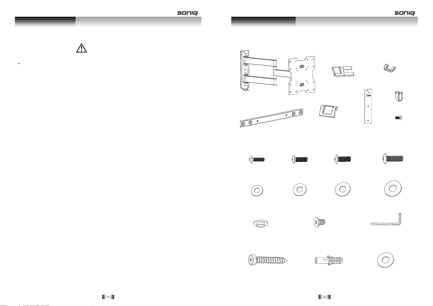
Component ChecklistSafety Instruction
IMPORTANT: Ensure that you have received all parts according to the component checkli st prior to installing.
If any parts a re mi ssi ng or f aulty, te lephone yo ur lo cal d ist ributor for a rep lac eme nt.
• Do not begin the installation until you have read and understood the instructions
and warnings contained in this installation sheet. If you have any questions
regarding any of the instruction or warning, please contact your local distributor.
• This mounting bracket was designed to be installed and utilized ONLY as
specified in this manual. Improper installation of this product may cause damage
or serious injury.
• This product should only be installed by someone of good mechanical ability,
with basic building experiences and fully understanding of this manual.
• Make sure that the supporting surface will safely support the combined load of
the equipment and all attached hardware and components.
• If mounting to wood wall studs, make sure that mounting screws are anchored
into the center of the studs. Use of a stud finder is highly recommended.
• Always use an assistant or mechanical lifting equipment to safely lift and position
equipment.
• Tighten screws firmly, but do not over tighten. Over tightening can damage the
items, greatly reducing their holding power.
Packa ge M
M4x14
D4 wash er
artic ula ted a rm as sembly
exten sio n bar ( x )
(x4)
M-A
M-E
A
2
B
M5x14 ( x4)
(x4) D (x4)
5 washe r
M-B
M-F
decor ati ve co ver C(x2)
middl e dec ora tiv e
cover ( x1)
D
M6x14
M-C
D6 (x4)
washe r
M-G
wall te mpl ate F(x1)
(x4)
cable c ove r
E
cable d ip (x 1)
M4 (x1)
M8x15
M-D
D8 (x4)
washe r
M-H
(x1)
G
H
(x4)
• This product intended for indoor use only. Using this product outdoors could
lead to product failure and personal injury.
ø13.5 xø5 .5x 3.2 ( x4)
Packa ge W
ST6.3 x55 (x4)
M-I
W-A
M6 (x4)
M-J
concr ete a nch or
W-B
(x4)
4mm allen key
M-K
D6 wash er (x 4)
W-C
(x1)
Page 3

2. Mount on Solid Brick and Concrete BlockDisassemble VESA Plate
loose n
remov e
1. Mount on Wood Stud Wall
W-C
W-A
55mm
55mm
(2.2")
(2.2")
With arrow head
pointing up
ø 4.5mm
(ø 3/16")
1
2
3
Drill pilot holes
X X
W-B
W-C
With arrow head
pointing up
W-A
60mm
60mm
(2.4")
(2.4")
ø 10mm
(ø 3/8")
1
2
Drill pilot holes
X X
Screw the wall
mount onto
the wall
Screw the wall
mount onto
the wall
WARNING
• Make sure that mounting screws are anchored into the center of the studs. Use of a stud finder
is highly recommended.
• Installers are responsible to provide hardware for other types of mounting situations.
• Installer must verify that the supporting surface will safely support the combined load of the
equipment and all attached hardware and components.
WARNING
• When installing wall mounts on cinder block, verify the actual con crete thic kness is at lea st
1-3/8" (35mm) for using the concrete anchors. Do not drill into mortar joints! Be sure to
mount in a solid part of the block, generally 1" (25mm) minimum from the side of the block.
It is suggested electric drill on slow setting is used to drill the hole instead of a hamme r drill
to avoid breaking out the back of the hole when entering a void or cavity.
• Installer must verify that the supporting surface will safely support the combined loa d of the
equipment and all attached hardware and components.
Page 4

3. Installing Decorative Covers
5. Install VESA Plate
Top of TV
Inser t bot h top a nd bo ttom plastic co ver s
4. Assemble VESA Adaptors
Then in sta ll th e mid dle decorativ e cov er.
M-J
TV
TV
TV
TV
M-C/M -D
M-G/M -H
or
M-A/M -B
M-E/M -F
M-I
Screw t he VE SA pla te on to the TV.
Tig hten all scr ews b ut do n ot ov er
tight en.
Page 5

6. Hook the TV onto the Wall Mount
7. Cable Management
4mm
Loose n the u ppe r fla t nut
spaci ng 4m m to VE SA pla te.
Hook the TV onto the wall mount
Attach cable clip to
the arm using
appropriate screw.
G
H
E
Connect cables to your TV and route cables through cable clip, then attach the cable cover to hold the cable in
place.
Note: Leave slack in cable for cantilever arm movement.
8. Adjustment
180 °
-3°
180 °
+3°
+15°
· the TV.
Level
· Place t he lo wer f lat n ut, tighten bot h fla t nut s.
-15°
Adjust to the desired location or tilt.
Page 6

9. Adjustment
M-J
Acc ordi ng to the diffe rent weigh t of the di spla y, it is necessary to sli ghtl y loosen or tig hten the adj ustm ent
scr ew using the su pplied Allen key.
Maint ena nce
• Check t hat t he br ack et is secure and sa fe to u se at r egu lar interv als (at l eas t every three mon ths ).
• Pleas e con tac t you r dealer if you hav e any q ues tio ns.
 Loading...