

Page 1

MNT-PTX-150
PTX150
DIRECT DIGITAL
PAGING TRANSMITTER
SONIK - 1999
User Manual
Sonik Technologies Corporation
310 Via Vera Cruz, Suite 111
San Marcos, CA 92029 USA
Phon e: 760-752-1011
FAX: 760-752-1411
Email: [email protected]
Page 2

MNT-PTX-150
CONTENTS
1. INTRODUCTION...............................................................................1
1.1 GENERAL...................................................................................................1
1.2 I NDICATORS AND CONNECTORS..............................................................2
1.2.1 FRONT PANEL INDICATORS....................................................................................2
Table1.2.1 LED indication of Transmitter status.........................................................................2
1.2.2 REAR PANEL CONNECTORS AND SOCKETS...........................................................3
Table 1.2.2 Rear Panel functions..............................................................................................3
Figure 1.2.0 Rear view............................................................................................................. 3
1.3 DESCRIPTION OF OPERATION..................................................................4
Figure 1.3.1 Block Diagram of the Paging Transmitter................................................................4
2. SPECIFICATIONS............................................................................ 6
Table 2.0.1 - Physical Specifications.........................................................................................6
Table 2.0.2 - General Specifications ......................................................................................... 6
Table 2.0.3 - RF Characteristics...............................................................................................6
3. INITIAL INSTALLATION...................................................................7
4. CONNECTION TO NETWORK.........................................................9
Table 4.0.1 List of the DB37 connector pins..............................................................................9
5. TROUBLE SHOOTING GUIDE....................................................... 1 0
Table 5.0.1 - Trouble Shooting ...............................................................................................10
6. USING THE RDK RE MOT E TX DIAGNOSTIC PROGRAM............ 10
7. GLOSSARY OF TERM S................................................................. 11
Appendix A: RDK Softwar e User's Gui de ..........................................1
Appendix B: Basic Connection Betwe e n Tx and Controller............. 1
Appendix C: Satellite Link Mode Configuration for External NIU....1
Doc Ref :
SONIK - 1999
150-100
Issue :
1.00
Page 3

MNT-PTX-150
1. INTRODUCTION
INTRODUCTION
1.1 GENERAL
The SONIK PTX150 Paging transmitter is a state of the art DSP/DDS (Digital Signal
Processor/Direct Digital Synthesis) based device capable of generating all paging
modulation formats, and is designed as a general purpose transmitter for all speed paging
systems.
Construction of the transmitter is fully modular. Internally, the case is divided into
compartments with PCB’s arranged in modules, all interconnected by plug/sockets. All
modules can be replaced without the use of a soldering iron. Replacement modules do not
require alignment or tuning.
The SONIK PTX150 transmitter incorporates a universal AC supply and can also operate
from a single DC supply for battery back up operation. Software permits the option of
”Hot standby” with auto changeover initiated by software selectable fault conditions.
The SONIK PTX150 transmitter is designed for 100% duty cycle at up to 55°C ambient
conditions amd utilizes advanced cooling technology to maintain very low power
transistor junction temperatures. This approach means assures ultra reliable power
amplifier performance.
The power amplifier temperature is monitored and if the temperature rises above a preset
amount (35°C), the diagnostics system is alerted and the fan and cooling system is
activated. The transmitter is protected by over temperature feedback control to the PA
drive input and also incorporates auto fold back for high VSWR conditions.
An external frequency reference input is designed to handle standard reference sources
and will lock the transmitter to the external reference. An internal ±1 PPM TCXO
(Temperature Compensated Crystal Oscillator) is provided as standard if no external
reference is available.
In POCSAG wide area systems, the carrier can be ”dithered” by what is known as a
”Black noise” algorithm, to minimize cancellation of equal amplitude carriers from
adjacent transmitters. This technique has been used for at least 12 years and is superior to
the Carrier offset method. High stability carriers are unnecessary for the carrier dithering
technique. For high speed ERMES and FLEX systems, the carrier can be offset in 1Hz
steps.
Doc Ref :
SONIK - 1999
150-100
Issue :
1.00
Page :
1
Page 4
MNT-PTX-150
1.2 INDICATORS AND CONNECTORS
INTRODUCTION
1.2. 1 FRONT P ANE L INDICATORS
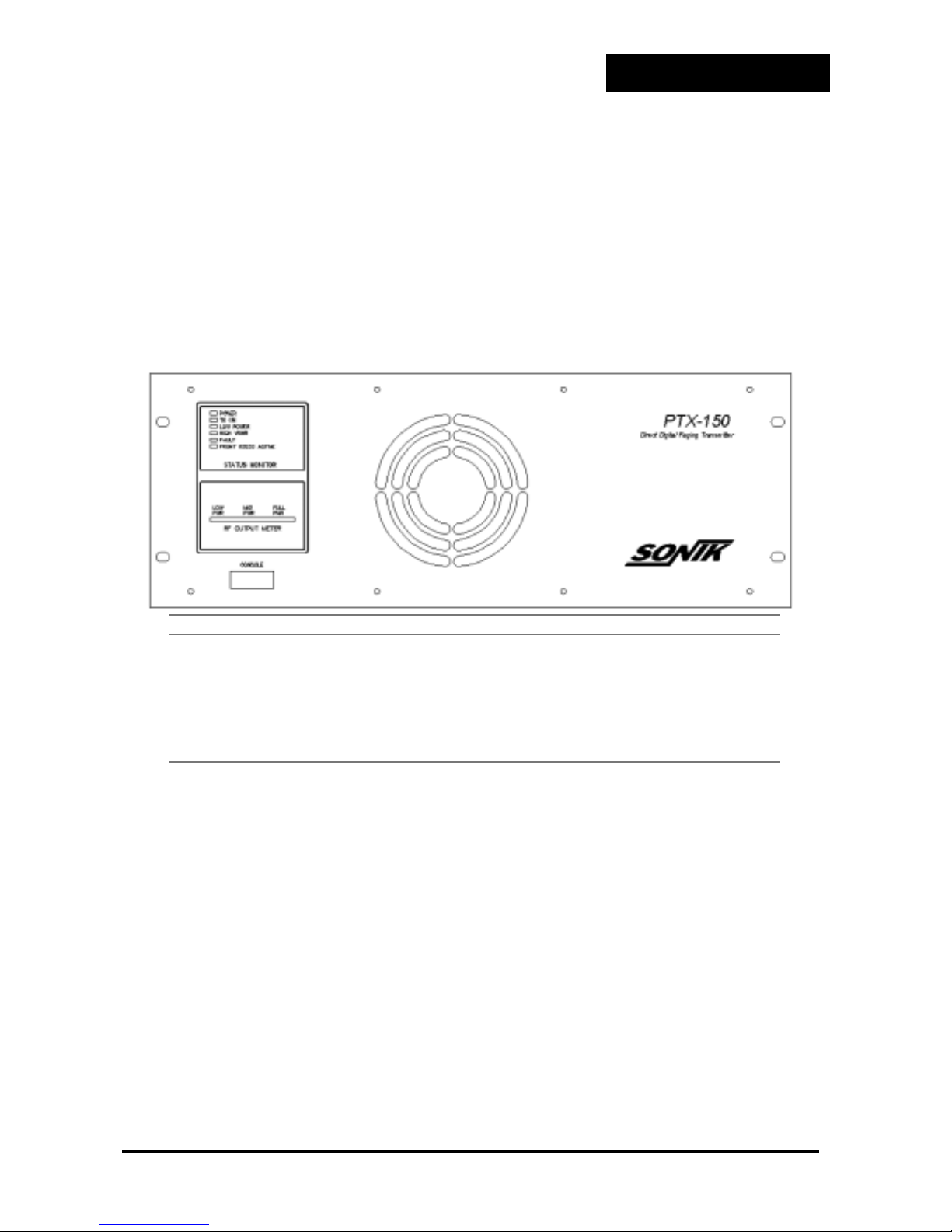
Table 1.2.1 illustrates the front panel diagnostic LEDs.
Each LED shows the status of selected functions of the transmitter.
In the following figure, the ”CONSOLE” connector acts as the standard RS232 interface
for local programming.
LED FUNCTION
POWER Indicates that +24VDC is available from the Power supply.
TX ON Transmitter is transmitting RF power.
LOW POWER RF output is below alarm threshold set in software.
HIGH VSWR Antenna port matching is out of specifications set in software.
FAULT Global fault condition in the transmitter. Refer to ‘Trouble
shooting Guide’ in the handbook.
FRONT RS232 ACTIVE Indicates that the front panel RS232 port is in use.
Table1.2.1 LED indication of T r ansmitter st at us
Doc Ref :
SONIK - 1999
150-100
Issue :
1.00
Page :
2
Page 5
1.2. 2 REAR PANEL CONNECTORS AND SOCKET S
y
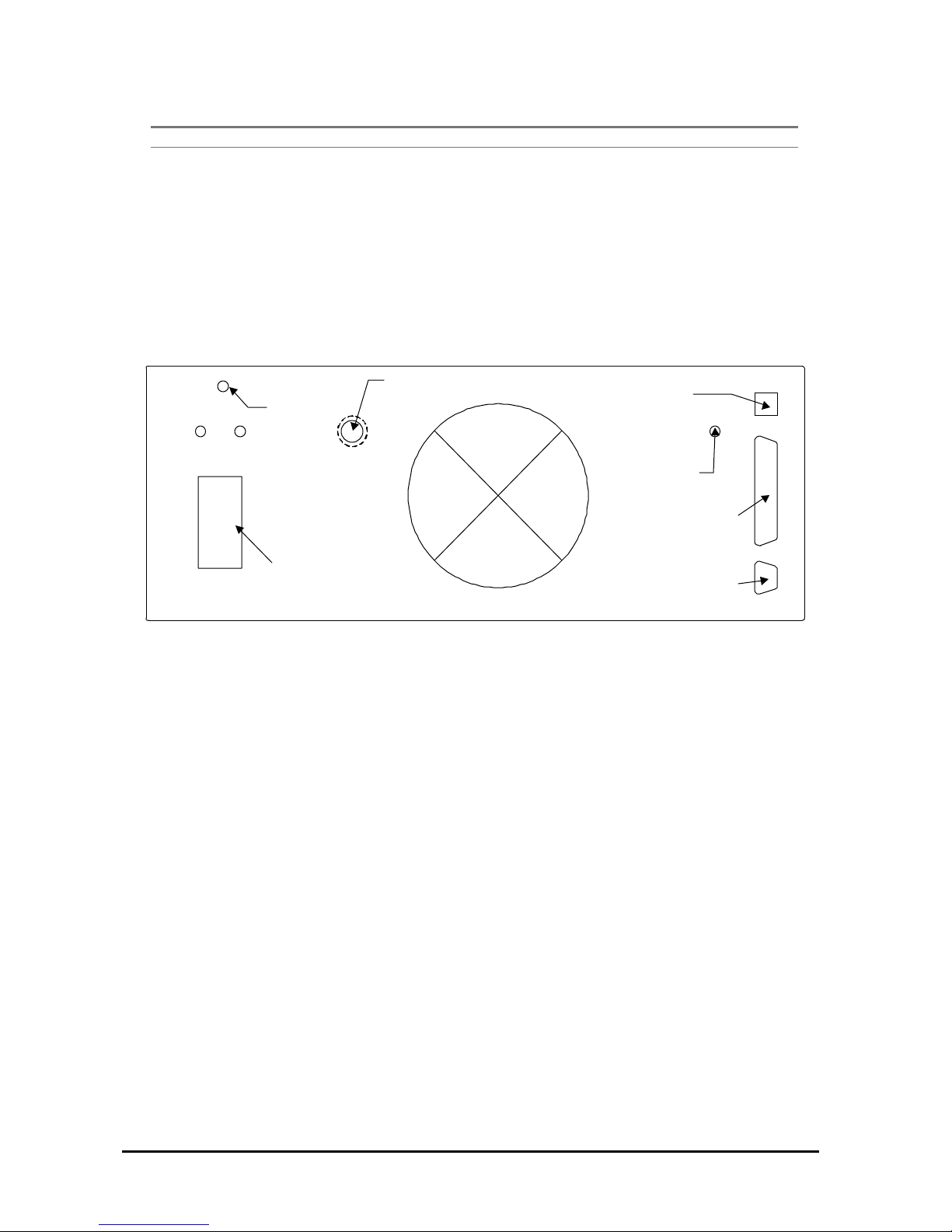
CONNECTOR FUNCTION
N-TYPE The RF output of the paging transmitter
DB9 The connection for the external dial modem interface
MAINS INPUT 115/220VAC 50/60Hz input voltage
DB37 Transmitter Controller unit connection point
BNC External reference input (5-15MHz)
RJ11 Internal link MODEM interface
Table 1.2.2 Rear Panel functions
MNT-PTX-150
+24V GND
System
MAINS INPUT:
AC Power In &
Swtch/Fuse assembl
N-TYPE:
RF Output
Figure 1.2.0 Rear view
RJ11: Link Modem
Interface
BNC: External
Frequency Source
Input
DB37: LIU Interface
DB9: RS232, Dial MODEM
Doc Ref :
SONIK - 1999
150-100
Issue :
1.00
Page :
3
Page 6
MNT-PTX-150
1.3 DESCRIP TION OF OPERAT ION
37 pin DIN
DSP/DDS circuits,
microprocessor,
modulator and TCXO
External Freq. standard.
(optional)
Frequency converter
VCO and channel
Auto Diagnostics
and mixer
synthesizer
Circuits
INTRODUCTION
RF filter and
preamp.Nominal 300
mW/50 ohms
20 Watt Driver
Amplifier.
Power Splitter
75 Watt
Power
Amplifier
Combiner
75 Watt
Power
Amplifier
AC Power supply
(optional)
Filter
RF OUT
Figure 1.3.1 Block Diagram of the Paging Tr ansmitter
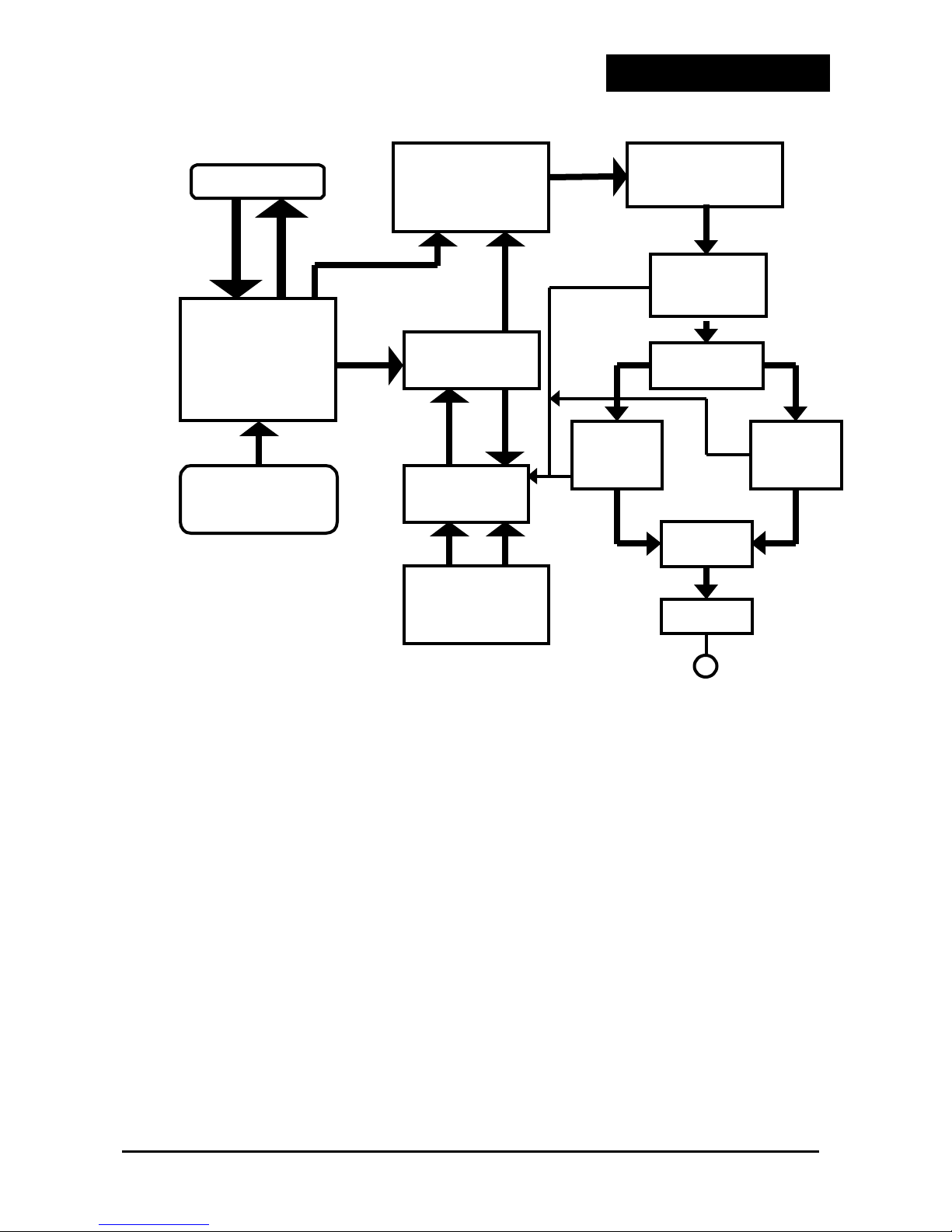
A block diagram of the operation of the paging transmitter is shown in figure 1.3.1.
On the exciter printed circuit board, the DDS/DSP circuitry generates a 10.7 MHz
modulated signal, referenced to the internal TCXO or an external reference frequency
source.
(The reference source is selected in a software option).
The external reference is only required when stability of the carrier better than ±1PPM is
required.
in software)
(Parameters such as rise time, absolute deviation, mode etc are all selectable
.
The 10.7 MHz modulated signal is processed through a filter before being applied to the
first mixer. The LO input to the first mixer is a high quality 235 MHz unmodulated signal
with very low phase noise. The mixing products are filtered and buffered with two stages
of SAW filtering, and the low side product of 224.3 Mhz is then applied to the second
mixer. The Second mixer LO frequency is equal to final frequency + 224.3 MHz. Channel
change is effected by the VCO supplying the second mixer.
Doc Ref :
SONIK - 1999
150-100
Issue :
1.00
Page :
4
Page 7

MNT-PTX-150
The final frequency output from the second mixer is filtered, buffered and amplified to
300 mW at 50 ohms, suitable for presentation to the Power amplifier modules.
Note that the TCXO of 9.6 MHz supplies the DSP, first LO and second LO to provide the
accuracy required for final frequency. The DSP circuitry actually uses 38.4 MHz which is
derived from a crystal at that frequency phase locked to the 9.6 MHz TCXO.
Note also that for high stability options, the 9.6 MHz TCXO is replaced when an external
reference signal is applied to the BNC connector at the rear of the Transmitter. Selection
of this function is via software.
Automatic level control (ALC) of the exciter is affected by the on board Microprocessor
in the Exciter module.
The Exciter output is coupled via coaxial cable to the 20W driver amplifier in a separate
compartment in the chassis.
The driver comprises 2 RF amplifier stages, a Harmonic filter and directional coupler for
generation of forward and reverse power voltage analogs.
The output of the 20W driver amplifier goes into a power splitter, and the two 90 degree
out of phase output signals from the power splitter are feed into two 75W power
amplifiers.
The outputs of the two 75W power amplifiers are then combined to produce 100W
continuous RF output power.
The forward and reverse power output is also monitored using a directional coupler. The
exciter microprocessor computes VSWR from the directional coupler outputs.
ALC is also effected in the PA to ensure stable output for all environmental and external
conditions.
The transmitter is designed to operate from a single +24VDC power source with the
internal AC power supply generating the required voltage.
A 37 Pin DIN female socket provides the connection for Data, Clock, mode, channel
change, and PTT control from an external Line interface unit
Instructions’ for details regarding pin connections)
.
. (Refer to ‘Installation
If no external PTT control exists, provision is made for PTT control by the detection of
incoming data on the TX DATA (Lbit) pin of the 37 way connector.
(Hang time for this
automatic PTT control is selectable in software).
A DB9 female socket provides access for either a PSTN dial modem or a PC.
The transmitter can be monitored by a central or local computer for automatic diagnostics
or polling.
The PC and RDK software can be used on site to reprogram parameters of the transmitter.
Doc Ref :
SONIK - 1999
150-100
Issue :
1.00
Page :
5
Page 8

MNT-PTX-150
2. SPECIFICATIONS
Dimensions 19” rack mount, 7H x 18.3D in (178mm x 465mm)
Shipping weight 40 lbs (18 kg).
Operating voltage
Operating temperature
Operating humidity
Modulation generation Discrete DSP in conjunction with DDS Chip set.modulation.
Modulation modes POCSAG 512, 1200 or 2400
Modulation characteristics Rise and fall times default to standard settings as defined by
Modulation rates External clock dependant if not in POCSAG mode. Any rate
Channel switching Up to 16 preset channels selectable by 4 channel lines.
Interface connection 37 pin female DIN socket provided for connection to C-net, or
Diagnostics Auto dial up system with WINDOWS based central station
Carrier offsets
Launch Time Delay
SPECIFICATIONS
PHYSICAL
Table 2.0. 1 - Physical Specifications
GENERAL
110 / 220VAC±20%
-15 to +55°.C
0 to 95% RH @ 50°C
ERMES to 6400 BPS
FLEX™ 2 level and 4 level at all data rates
ERMES/ FLEX™/POCSAG recommendations.
up to 6400 BPS.
other network support decoders. For POCSAG connection,
Clock input line is not required and only TX DATA (Lbit)
line is used.
monitoring software. Analogs and digital inputs are supported
by the diagnostics package. Standard alarms are also made
available on 37 pin DIN socket for connection to network
interfaces such as C-NET.
Up to ±3000 Hz in 1 Hz steps.
0 to 40ms in 5uS steps.
RF output power
Frequency range 138 to 174MHz
Turn on time <25ms from TX ON signal to full power.
Frequency stability
External frequency reference
Spurious performance Conducted and radiated spurii better than 70 dBc.
Adjacent channel performance Better than 70 dBc.
Doc Ref :
SONIK - 1999
150-100
Table 2.0. 2 - General Specifications
RF CHARACTERISTICS
100 Watts ±0.5dB into 50Ω
Standard ±1PPM
(optional external high stability frequency source).
From 5 to 15 MHz at any level from -10 to 0 dBm/ 50Ω.
External signal can be sinusoid or square wave.
Table 2.0. 3 - RF Character istics
Issue :
1.00
Page :
6
Page 9

MNT-PTX-150
3. INITIAL INSTALLATION
INSTALLATION
The following equipment will be required to test the transmitter:-
1. A good quality 50Ω dummy load or 30 dB high power attenuator suitable for 150W
continuous operation at 174 MHz and with a VSWR of better than 1.15:1.
2. A 486 or better PC with at least 8 Mbyte of RAM and one serial port, installed with
RDK software.
A suitable cable to connect the serial port of the PC to the dial Modem port of the
3.
transmitter.
Details of the required cable wiring are to be found in ‘CONNECTION
TO THE NETWORK’ section of the manual.
4. A suitable AC lead to suit the country where the transmitter is to be tested.
5. A ”Thruline” wattmeter fitted with the appropriate insert.
6. Suitable low loss RF cables and connectors.
Remove the SONIK PTX150 transmitter from its packing case and on a clean flat surface,
carefully examine the transmitter for physical damage. Pay particular attention to the rear
plugs and sockets. Verify that the rear cooling fan is free to rotate and does not have
packing material in it which may prevent the blades from rotating.
Connect a good quality 50Ω dummy load rated for at least 150W continuous power at the
frequency of operation of the transmitter; to the transmitter RF output ”N” connector on
the rear panel.
WARNING: ATTEMPTING TO OPERATE THE TRANSMITTER
WITHOUT A PROPER LOAD CONNECTED TO THE RF
OUTPUT PORT WILL VOID THE WARRANTY
The SONIK PTX150 series Transmitters have a detailed and comprehensive test
sequence programmed in and this program activates immediately power is applied to
the unit.
If the beeps and light sequencing occurs as specified, then all is well.
•
If a dial Modem is connected, the start up sequence differs from that which would
•
occur if a dial Modem was not connected.
With the transmitter located free of nearby objects which may block airflow through
•
the unit, switch on the transmitter by connecting the AC power cord to the AC supply
and operating the AC ON/OFF switch on the rear panel of the transmitter.
.
Doc Ref :
SONIK - 1999
150-100
Issue :
1.00
Page :
7
Page 10

MNT-PTX-150
Connect a PC (fitted with RDK software) to either the front panel console or rear
•
panel modem ports of the transmitter, activate the RDK program and verify correct
connection by selecting the
window. The screen then prompts by asking
connection and the transmitter system is operational, respond
READ
field on the
Transmitter Configuration
ARE YOU SURE
”
. If the PC
”
YES
”
and the
”
transmitter parameters are read into the PC screen.
NOTE: Alarm trip points and operating parameters are preset in the factory and
normally there will be no need to change these. For instructions on how to change the
alarm settings and status parameters, use the PC mouse to revert to the Transmitter
Configuration window. Select the Alarm Settings field and note the presets.
If Auto dial out functions are required (PSTN dial modem connected), use the mouse to
select which alarms will initiate a dial back (Enable).
A copy of all factory defaults can be saved onto hard disk by selecting the SAVE field
and typing in an appropriate file name.
The power up sequence is as follows
1. A tone is heard after power is applied and all front panel lights should be ON.
2. After approximately 5 seconds the LEDs on the front panel will go off in sequence
starting with the
FAULT
and the only remaining LED left ON is
POWER
.
3. The tone then stops for half a second while the SONIK PTX150 transmitter checks for
a dial modem connected to the dial modem port.
If no dial modem is detected then a brief tone is heard.
If a dial modem is detected then a series of tones will be made by the SONIK PTX150
transmitter to indicate that a dial modem was detected.
For connections into a remote RDK network this test
must pass
if a dial modem is
connected.
4. After an additional 5 seconds the SONIK PTX150 transmitter will be ready for normal
operation.
NOTES: WHEN USING EXTERNAL TELEPHONE DIAL MODEM
1. When an incoming call is detected the buzzer will ring as an indication.
2. When a SONIK PTX150 transmitter is connected the
POWER
LED blinks to indicate
that the unit is on-line to the host RDK software.
Doc Ref :
SONIK - 1999
150-100
Issue :
1.00
Page :
8
Page 11

MNT-PTX-150
4. CONNECTION TO NETW ORK
CONN ECTION
Once the transmitter has been configured for the network, it is now necessary to install
the unit into the station and interface to the LIU (Line Interface Unit).
Verify that the antenna lead is connected to the station antenna. Install a Thruline
•
Wattmeter in series with the transmitter and antenna lead.
If a PSTN connection and dial Modem are available, install the dial modem and
•
connect it to the dial Modem port (on the rear of the transmitter).
Use a standard
DCE to DTE RS232 interface cable (usually supplied with the dial modem).
If an external frequency reference is used, select that option in software and connect
•
the source via a 50Ω coaxial cable and BNC male plug to the BNC socket at the rear
of the transmitter.
Identify the appropriate data, clock and mode control connections from the LIU and
•
connect them to the appropriate pins on the DB 37 connector at the rear of the
transmitter. The correct connections will vary depending upon the LIU used and the
mode of operation. Refer to Table 4.0.1 of pin outs for the DB37 connector.
PIN No. LIU Name FUNCTION
1 In8 Protocol select line
5 In4 Frequency select line
6 In3 Frequency select line
7 In2 Frequency select line
8 In1 Frequency select line
11 TXON Transmitter key
15 TDL TX DATA, TTL (L-Bit)
16 TDM TX DATA, TTL (H-Bit, 4-level)
18 TDCL Clock for synchronization data
19 GND Ground
21 Out10 Reflected power alarm 2 (not used)
22 Out11 Output power high alarm
23 Out12 Output power alarm 2 (not used)
26 Out3 TX Synthesizer alarm
29 Out6 Output power low alarm 1
30 Out7 Reflected power alarm 1
31 Out8 Fan alarm
Table 4.0.1 List of the DB37 connector pins.
Determine if PTT control is via the DB37 connector or will have to be automatic upon
•
the detection of data.
If desired, check the setting for the transmitter Hang Time (time that transmitter stays
•
keyed on after the last data transition has occurred on the TX DATA TTL [Lbit] pin).
This function can be altered in software
Connect AC power to the transmitter and note that the appropriate test cycle occurs.
•
The transmitter is now ready to operate.
Doc Ref :
SONIK - 1999
150-100
Issue :
1.00
.
Page :
9
Page 12
MNT-PTX-150
5. TROUBLE SHOOTING GUIDE
PROBLEM
The transmitter has a comprehensive test program which initiates on first application
of power. It is important to understand the start up sequence to determine a likely fault
scenario.
Dial Modem connected but the system does
not indicate a connection
No LEDs light up or no tone heard
No RF output power
Table 5.0.1 lists possible symptoms, and solutions to those symptoms.
SYMPTOM POSSIBLE PROBLEM
• Power to dial modem is off.
• Cable is installed incorrectly
• Dial Modem has not been set up as Hayes compatible
9600,8,N,1
• Mains power is off
• Fuse has blown on input connector
• faulty power supply
• The SONIK PTX150 transmitter will turn off the RF
output if any potentially fatal faults develop in the unit.
• Fault can be caused by the LIU selecting a channel that is
not configured in software.
• If the fault LED is ON you must find out what fault is
causing the problem through the diagnostic software and
repair, or notify the Supplier
Table 5.0.1 - Tr ouble Shooting
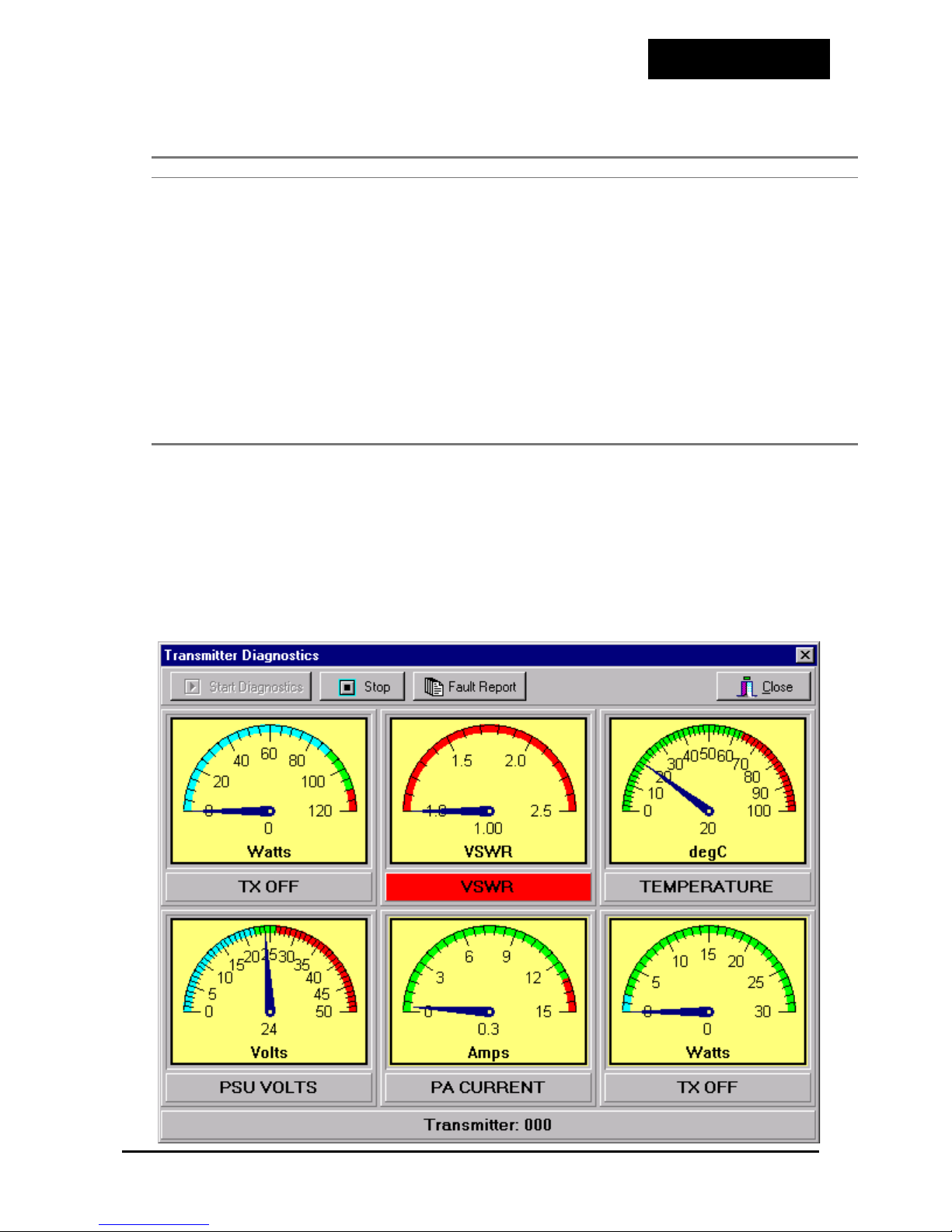
6. US ING THE RDK REMOTE TX DIAGNOSTIC PROGRAM
This program is used to monitor all of the transmitter functions in a real-time mode.
To initialize, have a functional transmitter working then select the
Transmitter Diagnostic
icon on the PC and the program will start to run.
RDK Remote
Doc Ref :
SONIK - 1999
150-100
Issue :
1.00
Page :
10
Page 13

MNT-PTX-150
From the opening screen, select
Tx Diag
and the above display will result.
Each meter indicates the true state of that transmitter function and will change in real time
as adjustments to that transmitter are made.
Any of the functions that has a problem (when the needle is not in the
have its label light up
allowing you to immediately identify the problem area.
RED
7. GLOSSARY OF TE RMS
GREEN
GLOSSARY
This section gives an index of how different fonts are used to represent operations
between the computer and the radio and the technical terms used in this manual.
Window
This indicates the user should be in a particular window within the
RDK control program to perform a particular operation.
<KEY>
DDS
DSP
ALC
PC
The < > symbols indicate a key must be pressed on the keyboard.
Direct Digital Synthesis
Digital Signal Processor
Automatic Level Control
Personal Computer
area) will
LIU
Line Interface Unit
Doc Ref :
SONIK - 1999
150-100
Issue :
1.00
Page :
11
Page 14
MNT-PTX-150
Appendix A: RDK Softwar e User’s Guid e
One set of RDK software includes 2 compressed files and one terminal
application program.
Running Requirements:
1) PC: 486 or above, at least 8M memory, one 1.44M floppy disk drive, one RS-232
serial port, one printer port.
2) Cable: Serial port cable with Pin2, Pin3, Pin5 on the one side connected to Pin3,
Pin2, Pin5 on the other side.
3) Operating System: Windows95/98, Windows NT.
I.
II.
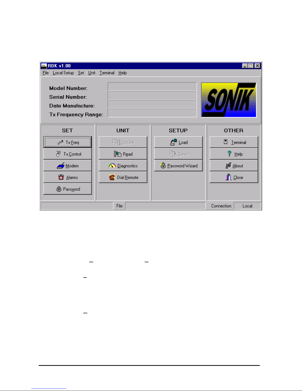
Select item ”Comms Setup” from ”Local Setup” menu to setup local serial port.
Click ”Tx Freq” button to set frequency values for the transmitter. The selection
of different frequencies is determined by changing the input voltage level (0V or
5V) at Pin5,6,7,8 of DB37, for example, leaving Pin5,6,7,8 to be floating (5V)
means the selection of the first frequency value (channel 00).
III. Click ”Tx Control” button to set parameters for the transmitter: RF power,
external frequency source, data polarity, PTT signal, paging protocol, etc.
Comments: low level (0V) of Pin1 of DB37 means the selection of default protocol
1; while high level (5V) of Pin1 of DB37 means the selection of default protocol 2.
The two default protocol settings should not be the same value at the same time so
that you can select different protocol (POCSAG or FLEX) just by changing the
input level of Pin1 of DB37.
Doc Ref :
SONIK - 1999
150-100
Issue :
1.00
Page :
1
Page 15

MNT-PTX-150
IV. Click ”Modem” button to configure dial-out parameters and PMD board.
V.
Click ”Alarms” button to set alarm limits for RF power, High VSWR,
Temperature, Voltage and High Current.
VI. Click ”Read” or ” Update” button to Read or Update Transmitter Parameter
Settings.
VII. Click ” Diagnostics” button to Diagnose the transmitter with real-time
parameters (Forward Power, VSWR, Temperature, Power Voltage, PA Current
and PA driver power) monitoring.
VIII. Click ”Dial Remote” button to dial remote transmitter with an internal dialer.
Before dialing, please be sure to set the dial MODEM parameters using the
following AT commands: ATS0=1, AT&D0, AT&K0, AT&W0. Then, select item
”Modem Setup” or ”Dialer Setup” from ”Local Setup” menu to setup local dial
MODEM and dialer.
IX.
X.
Click ”Load” or ”Save” button to Load/Save the current transmitter settings
from/to a local file.
Click ”Terminal” button to access the terminal program.
Doc Ref :
SONIK - 1999
150-100
Issue :
1.00
Page :
2
Page 16

MNT-PTX-150
Appendix B: Basic Connection Between Tx and Controll er
I.
!
TB3-2: Tx Clock Connected to DB37-18: Data Clock
TB3-4: Tx key Connected to DB37-11: Tx Key
TB3-8: GND Connected to DB37-19: Ground
TB4-2: Rx FQ1 Connected to DB37-16: Tx Data, High Bit, TTL
TB4-3: Rx FQ2 Connected to DB37-15: Tx Data, Low Bit, TTL
Flex Mode: (Connect to MOTOROLA External NIU)
Connection between SONIK PTX150 Transmitter and External NIU:
External NIU(TB3, TB4) Transmitter(DB37)
DB37-1 to DB37-19
!
Connection between External NIU and GPS Receiver:
"
GPS time signal:
GPS Receiver
(serial port, 9 Pin)
Pin 1 Connected to Pin 4
Pin 2 Connected to Pin 3
Pin 3 Connected to Pin 2
Pin 4 Connected to Pin 1
Pin 5 Connected to Pin 5
Pin 6 to Pin 1 Pin 6 to Pin 1
Pin 7 Connected to Pin 8
Pin 8 Connected to Pin 7
External NIU
(option port, 9 Pin)
"
GPS 1pps Signal: connected the ”1pps OUT” port of GPS receiver to the ”1Hz
IN/OUT” port of External NIU with a RCA video cable.
!
When the transmitter needs to get external frequency source from External NIU,
connect the ”REF IN/OUT” port of External NIU to the ”External Frequency Input”
port of SONIK PTX150 transmitter with a BNC cable.
Doc Ref :
SONIK - 1999
150-100
Issue :
1.00
Page :
1
Page 17

MNT-PTX-150
II.
!
Connection between SONIK PTX150 Transmitter and External NIU:
FLEX Mode: (Connect to Glenayre C2000 Controller)
C2000 ( J4 ) Transmitter(DB37)
J4-10: GND Connected to DB37-19: Ground
DB37-1 to DB37-19
J4-13: TXKEY+ Connected to DB37-11: Tx Key
J4-3: TD0+, Msb Connected to DB37-15: Tx Data, Low Bit, TTL
J4-34: TD1+, Lsb Connected to DB37-16: Tx Data, High Bit, TTL
J4-18: Data Clock+ Connected to DB37-18: Data Clock
J4-7: Freq2 Connected to DB37-6: Freq2
J4-6: Freq1 Connected to DB37-7: Freq1
J4-36: Freq0 Connected to DB37-8: Freq0
!
When the transmitter needs to obtain the external frequency source from C2000,
connect the ”10M REF OUT” port of C2000 to the ”External Frequency Input” port
of SONIK PTX150 transmitter with a BNC cable.
III.
POCSAG Mode:
Encoder Transmitter ( DB37 )
Tx Data Connected to DB37-15: Tx Data, Low Bit
PTT Connected to DB37-11: Tx Key
GND Connected to DB37-19: Ground
DB37-1 to DB37-19
Doc Ref :
SONIK - 1999
150-100
Issue :
1.00
Page :
2
Page 18

MNT-PTX-150
Appendix C: Satellite Link Mode Configuration for External NIU
I.
!
II.
!
III. Software configuration for External NIU:
!
Connection between External NIU and SONIK PTX150 transmitter:
Connect the DATA, GND and CLK output signal of satellite receiver to TB1-5(Rx
Data), TB1-4(GND) and TB1-6(Rx CLK) of External NIU.
Jumper settings of External NIU:
S15 Pin 1 is set to be ON. Others remain intact.
The serial port settings are: COM1, 19200bps, N, 8, 1.
[ 0] NIU> set link
↵
link = fm2 @ 9600 from digital_in
[ 0] NIU> set align_type
↵
GPS Mode: Alignment type is gps
No GPS Mode: Alignment type is dir_sync
[ 0] NIU> config devid
[ 0] NIU> config sysid
[ 0] NIU> config txd
↵
↵
↵
[ 0] NIU> set maint_polarity
[ 0] NIU> show gps
[ 0] NIU> show status
[ 0] NIU> show alarm
[ 0] NIU> show config
[ 0] NIU> show dipsw
↵
↵
↵
↵
↵
; Link settings
; Syncronization mode
; Base station device ID.
; System ID.
; Paging data polarity.
↵
; Maintenance cycle polarity.
; At GPS mode, display current GPS settings.
; Display current External NIU status.
; Display alarms for External NIU.
; Display current NIU system parameters.
; Display current NIU jumper settings.
Doc Ref :
SONIK - 1999
150-100
Issue :
1.00
Page :
1
 Loading...