

Redbox Series,RB-SD1IP,RB-SD1,RB-DSD8,RB-FS42,RB-FS42DC,RB-FS82,RB-DSD1,RB-FS82DC
Table of contents
 Loading...
Sonifex Redbox Series,RB-SD1IP,RB-SD1,RB-DSD8,RB-FS42,RB-FS42DC,RB-FS82,RB-DSD1,RB-FS82DC User Handbook Manual

HANDBOOK
Redbox
User Handbook No 2
RB-SD1 Silence Detection Unit
RB-SD1IP Silence Detection Unit With Ethernet & USB
RB-DSD1 Digital Silence Detection Unit
RB-DSD8 8 Channel Silence Switcher
RB-FS42 Audio Failover Switcher, 4 Main I/O, 2 Standby I/O
RB-FS42DC Audio Failover Switcher, 4 Main I/O, 2 Standby I/O, DC PSU
RB-FS82 Audio Failover Switcher, 8 Main I/O, 2 Standby I/O
RB-FS82DC Audio Failover Switcher, 8 Main I/O, 2 Standby I/O, DC PSU
Manufacturers of audio & video
products for radio & TV broadcasters

Redbox Handbook 2
For the latest Sonifex handbook information please visit the
Sonifex website at www.sonifex.co.uk
This handbook is for use with the following product:
Redbox User Handbook No 2
Stock Code: 30-337
Artwork: AW10839A
Revision 3.04, September 2018
©Sonifex Ltd, 2018
All Rights Reserved
Sonifex Ltd, 61, Station Road, Irthlingborough,
Northants, NN9 5QE, England.
Tel: +44 (0)1933 650 700
Fax: +44 (0)1933 650 726
Email: sales@sonifex.co.uk
Website: http://www.sonifex.co.uk
Information in this document is subject to change without notice and does not represent a
commitment on the part of the vendor. Sonifex Ltd shall not be liable for any loss or damage
whatsoever arising from the use of information or any error contained in this manual.
No part of this manual may be reproduced or transmitted in any form or by any means, electronic
or mechanical, including photocopying, recording, information storage and retrieval systems, for any
purpose other than the purchaser’s personal use, without the express written permission of Sonifex
Ltd. Unless otherwise noted, all names of companies, products and persons contained herein are
part of a completely fictitious adaptation and are designed solely to document the use of Sonifex
product.
Made in the UK by

Contents
Contents
Product Warranty - 2 Year Extended ii
Sonifex Warranty & Liability Terms & Conditions ii
1. Definitions ii
2. Warranty ii
Unpacking Your Product iii
Repairs & Returns iv
Conformity iv
Safety & Installation of Mains Operated Equipment iv
Voltage Setting Checks iv
Fuse Rating iv
Power Cable & Connection iv
WEEE Directive v
Atmosphere/Environment v
Fitting Redboxes v
1 RB-SD1 Silence Detection Unit 1
Introduction 1
System Block Diagram 2
Rear Panel Connections and Operation 3
Front Panel Selectors and Indicators 5
Source Select and Indicator 6
Additional Modes 7
Technical Specifications RB-SD1 9
2 RB-SD1IP Silence Detection Unit With Ethernet & USB 10
Introduction 10
System Block Diagram 12
Rear Panel Connections and Operation 13
Mode DIP Switch Settings 13
Remote Alarms Connector 14
Front Panel Selectors and Indicators 16
RB-SD1IP Network Discovery and Webserver 19
Sonifex Service Discovery App 20
Home Page 21
Device Information 22
Network Settings 23
Configuration : Level & Time Settings 24
Configuration : Source Settings 25
Configuration : Alarm Settings 26
Configuration : SNMP Settings 27
Configuration : USB Settings 28
Configuration : Remote Settings 29
Configuration : GPIO Settings 30
Configuration : Physical Settings 31
Update 32
Technical Specification RB-SD1IP 33
3 RB-DSD1 Digital Silence Detection Unit 34
Introduction 34
Front Panel Controls and Indicators 36
Front Panel DIPSwitches 37
Rear Panel Controls 38
Remotes Connector 41
RB-DSD1 Inputs & Outputs 42
Serial Port Control 43
Serial Interface Commands and Responses 43
Serial Protocol RB-DSD1 43
SCi for RB-DSD1 46
Indication Page 47
Unit Setup Page 48
Miscellaneous Page 49
Special Modes 50
Technical Specification For RB-DSD1 51
4 RB-DSD8 8 Channel Silence Switcher 53
Front Panel Controls & Indicators 55
Status Buttons 55
DISPLAY LEDS 55
Rear Panel DIPSwitch Settings 58
RB-DSD8 Rear Panel Connections 61
Audio Connections 61
GPI/O Remotes Connector 62
Alarm Output Pins 63
Control Inputs 63
Slave Socket 64
USB Remote Control 64
Ethernet 64
Wordclock & AES Synchronisation Input 64
Dual IEC Main Inputs 64
Remote Control 65
Slave Control 65
Serial Interface Commands & Responses 65
Error Messages 68

Contents
SCi for RB-DSD8 68
Status Page 68
Channel Status Page 70
Miscellaneous Page 71
Webserver 72
Connecting to the device 73
Webserver Password 73
Updating The Firmware 74
Technical Specification RB-DSD8 75
5 RB-FS42 Audio Failover Switcher, 4 Main I/O,
2 Standby I/O 77
Introduction 77
Connections & Operation 80
Front Panel 80
Rear Panel Connections 82
25 Way D-Type Connection Details 83
Typical Application 85
Network Discovery & Webserver Configuration 86
Device Info 90
Home Page 91
Network Settings 92
SNMP 93
Channel Settings 94
Power Supply Trap Settings 95
GPO Settings 96
LED Settings 97
Update 98
Technical Specifications RB-FS42 99
6 RB-FS82 Audio Failover Switcher, 8 Main I/O,
2 Standby I/O 101
Introduction 101
Connections & Operation 104
Front Panel 104
Rear Panel Connections 106
25 Way D-Type Connection Details 107
Typical Application 109
GPI Operation 110
Network Discovery & Webserver Configuration 110
Device Info 114
Home Page 115
Network Settings 116
SNMP 117
Channel Settings 118
Power Supply Trap Settings 119
GPO Settings 120
LED Settings 121
Update 122
Technical Specifications RB-FS82 123

Figures
Figures
Fig A: RB-RK1Small Redbox Front Rack-mount Kit . v
Fig B: RB-RK2 Small Redbox Rear Rack-mount Kit. vi
Fig C: RB-RK3 Large Redbox Rear Rack-mount Kit. vi
Fig 1-1: RB-SD1 Front Panel 1
Fig 1-2: RB-SD1 System Block Diagram 2
Fig 1-3: RB-SD1 Rear Panel 3
Fig 1-4: RB-SD1 Front Panel 5
Fig 2-1: RB-SD1IP Front Panel 10
Fig 2-2: RB-SD1IP System Block Diagram 12
Fig 2-3: RB-SD1IP Rear Panel 13
Fig 2-4: RB-SD1IP Front Panel 16
Fig 2-5: Sonifex Service Discovery - Bonjour Page 20
Fig 2-6: Sonifex Service Discovery - Legacy Discovery Page 20
Fig 2-7: RB-SD1IP Screenshot of the Webserver Home Page 21
Fig 2-8: RB-SD1IP Screenshot of the Webserver Device Page 22
Fig 2-9: RB-SD1IP Screenshot of the Webserver Network
Settings Page 23
Fig 2-10: RB-SD1IP Screenshot of the Webserver Level
& Time Settings Page 24
Fig 2-11: RB-SD1IP Screenshot of the Webserver Sources Page 25
Fig 2-12: RB-SD1IP Screenshot of the Webserver Alarms Page 26
Fig 2-13: RB-SD1IP Screenshot of the Webserver SNMP Page 27
Fig 2-14: RB-SD1IP Screenshot of the Webserver USB Page 28
Fig 2-15: RB-SD1IP Screenshot of the Webserver Remotes Page 29
Fig 2-16: RB-SD1IP Screenshot of the Webserver GPIO Page 30
Fig 2-17: RB-SD1IP Screenshot of the Webserver
Physical Settings Page 31
Fig 2-18: RB-SD1IP Screenshot of the Webserver Update
Firmware Page 32
Fig 3-1: RB-DSD1 Front Panel 34
Fig 3-2: RB-DSD1 System Block Diagram 36
Fig 3-3: RB-DSD1 Front Panel Controls and Indicators 36
Fig 3-4: SILENCE Detect Duration DIPSwitch 37
Fig 3-5: SILENCE Detect Audio Trigger Level DIPSwitch 38
Fig 3-6: SILENCE Detect Stereo/Mono & Sync Source DIPSwitch 38
Fig 3-7: Rear Panel DIPSwitches 38
Fig 3-8: RB-DSD1 Rear Panel 42
Fig 3-9: Serial Port Default Settings 43
Fig 3-10: Indication Page 47
Fig 3-11: Unit Setup Page 48
Fig 3-12: Miscellaneous Page 49
Fig 4-1: RB-DSD8 Front Panel 53
Fig 4-2: RB-DSD8 Status Buttons 55
Fig 4-3: RB-DSD8 Controls & Indicators For Each Channel 55
Fig 4-4: RB-DSD8 Additional Indicators 57
Fig 4-5: RB-DSD8 Rear Panel DIPSwitches 58
Fig 4-6: RB-DSD8 Rear Panel 61
Fig 4-7: Audio & GPI/O Connector Detail 61
Fig 4-8: Audio Connector Pin Numbers 62
Fig 4-9: GPI/O Remotes Connector Pin Numbers 62
Fig 4-10: Communications Connectors 64
Fig 4-11: Status Page 69
Fig 4-12: Channel Status Page 70
Fig 4-13: Miscellaneous Page 71
Fig 4-14: General Settings Page 72
Fig 5-1: The RB-FS42 Front Panel 77
Fig 5-2: The RB-FS42 Diagram 79
Fig 5-3: The RB-FS42 Front Panel 80
Fig 5-4: The RB-FS42 Rear Panel 82
Fig 5-5: The RB-FS42 Female and Male Connectors 83
Fig 5-6: The RB-FS42 Bonjour Panel 89
Fig 5-7: The RB-FS42 Legacy Discovery Panel 89
Fig 5-8: The RB-FS42 Device Info Panel 90
Fig 5-9: The RB-FS42 Home Screen 91
Fig 5-10: The RB-FS42 Network Settings Screen 92
Fig 5-11: The RB-FS42 SNMP Screen 93
Fig 5-12: The RB-FS42 Channel Settings Screen 94
Fig 5-13: The RB-FS42 Power Supply Trap Settings Screen 95
Fig 5-14: The RB-FS42 GPO Settings Screen 96
Fig 5-15: The RB-FS42 LED Settings Screen 97
Fig 5-16: The RB-FS42 Update Screen 98
Fig 6-1: The RB-FS82 Front Panel 101
Fig 6-2: The RB-FS82 Diagram 103
Fig 6-3: The RB-FS82 Front Panel 104
Fig 6-4: The RB-FS82 Rear Panel 106
Fig 6-5: The RB-FS82 Female and Male Connectors 107

Figures
Fig 6-6: The RB-FS82 Bonjour Panel 113
Fig 6-7: The RB-FS82 Legacy Discovery Panel 113
Fig 6-8: The RB-FS82 Device Info Panel 114
Fig 6-9: The RB-FS82 Home Screen 115
Fig 6-10: The RB-FS82 Network Settings Screen 116
Fig 6-11: The RB-FS82 SNMP Screen 117
Fig 6-12: The RB-FS82 Channel Settings Screen 118
Fig 6-13: The RB-FS82 Power Supply Trap Settings Screen 119
Fig 6-14: The RB-FS82 GPO Settings Screen 120
Fig 6-15: The RB-FS82 LED Settings Screen 121
Fig 6-16: The RB-FS82 Update Screen 122

Warranty Registration
Register Online for an
Extended 2 Year Warranty
As standard, Sonifex products are
supplied with a 1 year back to base
warranty.
If you register the product online, you
can increase your product warranty
to 2 years and we can also keep
you informed of any product design
improvements or modifications.
To register your product, please go online to www.sonifex.co.uk/register
Sonifex Limited 61 Station Road Irthlingborough Northamptonshire NN9 5QE United Kingdom
Tel: +44 (0)1933 650 700 Fax: +44 (0)1933 650 726 Email: technical.support@sonifex.co.uk Internet: www.sonifex.co.uk
Product:
Serial No:

Warranty
Product Warranty - 2 Year Extended
As standard, Sonifex products are supplied with a 1 year back to base
warranty. In order to register the date of purchase and so that we can keep
you informed of any product design improvements or modifications, it is
important to complete the warranty registration online. Additionally, if you
register the product on the Sonifex website, you can increase your product
warranty to 2 years. Go to the Sonifex website at: http://www.sonifex.
co.uk/technical/register/index.asp to apply for your 2 year warranty.
Note: For your own records the product serial number is recorded on the
CE certification page of this handbook.
Sonifex Warranty & Liability Terms & Conditions
1. Definitions
‘the Company’ means Sonifex Ltd and where relevant includes companies
within the same group of companies as Sonifex Limited.
‘the Goods’ means the goods or any part thereof supplied by the Company
and where relevant includes: work carried out by the Company on items
supplied by the Purchaser; services supplied by the Company; and software
supplied by the Company.
‘the Purchaser’ means the person or organisation who buys or has agreed
to buy the Goods.
‘the Price’ means the Price of the Goods and any other charges incurred by
the Company in the supply of the Goods.
‘the Warranty Term’ is the length of the product warranty which is usually
12 months from the date of despatch; except when the product has been
registered at the Sonifex website when the Warranty Term is 24 months
from the date of despatch.
‘the Contract’ means the quotation, these Conditions of Sale and any
other document incorporated in a contract between the Company and the
Purchaser.
This is the entire Contract between the parties relating to the subject
matter hereof and may not be changed or terminated except in writing in
accordance with the provisions of this Contract. A reference to the consent,
acknowledgement, authority or agreement of the Company means in
writing and only by a director of the Company.
2. Warranty
a. The Company agrees to repair or (at its discretion) replace Goods
which are found to be defective (fair wear and tear excepted) and
which are returned to the Company within the Warranty Term
provided that each of the following are satisfied:
i. notification of any defect is given to the Company immediately
upon its becoming apparent to the Purchaser;
ii. the Goods have only been operated under normal operating
conditions and have only been subject to normal use (and
in particular the Goods must have been correctly connected
and must not have been subject to high voltage or to ionising
radiation and must not have been used contrary to the
Company’s technical recommendations);
iii. the Goods are returned to the Company’s premises at the
Purchaser’s expense;
iv. any Goods or parts of Goods replaced shall become the
property of the Company;
v. no work whatsoever (other than normal and proper
maintenance) has been carried out to the Goods or any part of
the Goods without the Company’s prior written consent;
ii

Warranty
vi. the defect has not arisen from a design made, furnished or
specified by the Purchaser;
vii. the Goods have been assembled or incorporated into other
goods only in accordance with any instructions issued by the
Company;
viii. the defect has not arisen from a design modified by the
Purchaser;
ix. the defect has not arisen from an item manufactured by a person
other than the Company. In respect of any item manufactured
by a person other than the Company, the Purchaser shall only be
entitled to the benefit of any warranty or guarantee provided by
such manufacturer to the Company.
b. In respect of computer software supplied by the Company the
Company does not warrant that the use of the software will be
uninterrupted or error free.
c. The Company accepts liability:
(i) for death or personal injury to the extent that it results from the
negligence of the Company, its employees (whilst in the course
of their employment) or its agents (in the course of the agency);
(ii) for any breach by the Company of any statutory undertaking as
to title, quiet possession and freedom from encumbrance.
d. Subject to conditions (a) and (c) from the time of despatch of
the Goods from the Company’s premises the Purchaser shall be
responsible for any defect in the Goods or loss, damage, nuisance
or interference whatsoever consequential economic or otherwise or
wastage of material resulting from or caused by or to the Goods. In
particular the Company shall not be liable for any loss of profits or
other economic losses. The Company accordingly excludes all liability
for the same.
e. At the request and expense of the Purchaser the Company will test
the Goods to ascertain performance levels and provide a report of
the results of that test. The report will be accurate at the time of the
test, to the best of the belief and knowledge of the Company, and the
Company accepts no liability in respect of its accuracy beyond that
set out in Condition (a).
f. Subject to Condition (e) no representation, condition, warranty or
other term, express or implied (by statute or otherwise) is given by
the Company that the Goods are of any particular quality or standard
or will enable the Purchaser to attain any particular performance
or result, or will be suitable for any particular purpose or use
under specific conditions or will provide any particular capacity,
notwithstanding that the requirement for such performance, result or
capacity or that such particular purpose or conditions may have been
known (or ought to have been known) to the Company, its employees
or agents.
g. (i) To the extent that the Company is held legally liable to the
Purchaser for any single breach of contract, tort, representation
or other act or default, the Company’s liability for the same
shall not exceed the price of the Goods.
(ii) The restriction of liability in Condition (g)(i) shall not apply to
any liability accepted by the Seller in Condition (c).
h. Where the Goods are sold under a consumer transaction (as defined
by the Consumer Transactions (Restrictions on Statements) Order
1976) the statutory rights of the Purchaser are not affected by these
Conditions of Sale.
Unpacking Your Product
Each product is shipped in protective packaging and should be inspected
for damage before use. If there is any transit damage take pictures of the
product packaging and notify the carrier immediately with all the relevant
iii

CE Certification
details of the shipment. Packing materials should be kept for inspection and
also for if the product needs to be returned.
Safety & Installation of Mains Operated Equipment
The product is shipped with the following equipment so please check to
ensure that you have all of the items below. If anything is missing, please
contact the supplier of your equipment immediately.
Item Quantity
Product unit 1
IEC mains lead fitted with moulded mains plug 1
Handbook and warranty card 1
If you require a different power lead, please let us know when ordering the
product.
Repairs & Returns
Please contact Sonifex or your supplier if you have any problems with your
Sonifex product. Email technical.support@sonifex.co.uk for the repair/
upgrade/returns procedure, or for support & questions regarding the
product operation.
Conformity
The products in this manual comply with the essential requirements of the
relevant European health, safety and environmental protection legislation.
The technical justification file for this product is available at Sonifex Ltd.
The declaration of conformity can be found at:
http://www.sonifex.co.uk/declarations
iv
There are no user serviceable parts inside the equipment. If you should
ever need to look inside the unit, always disconnect the mains supply
before removing the equipment covers. The cover is connected to earth
by means of the fixing screws. It is essential to maintain this earth/
ground connection to ensure a safe operating environment and provide
electromagnetic shielding.
Voltage Setting Checks
Ensure that the machine operating voltage is correct for your mains power
supply by checking the box in which your product was supplied. The voltage
is shown on the box label. The available voltage settings are 115V, or 230V.
Please note that all products are either switchable between 115V and 230V,
or have a universal power supply.
Fuse Rating
The product is supplied with a single fuse in the live conducting path of the
mains power input. For reasons of safety it is important that the correct
rating and type of fuse is used. Incorrectly rated fuses could present a
possible fire hazard, under equipment fault conditions. The active fuse is
fitted on the outside rear panel of the unit.
Power Cable & Connection
An IEC power connector is supplied with the product which has a moulded
plug attached.
The mains plug or IEC power connector is used as the disconnect device.
The mains plug and IEC power connector shall remain readily operable to
disconnect the apparatus in case of a fault or emergency.
The mains lead is automatically configured for the country that the product
is being sent to, from one of:

Safety & Installation
Territory Voltage IEC Lead Type Image
UK & Middle East 230V UK 3 pin to IEC lead
Europe 230V
USA, Canada and
South America
Australia & New
Zealand
Connect the equipment in accordance with the connection details and
before applying power to the unit, check that the machine has the correct
operating voltage for your mains power supply.
This apparatus is of a class I construction. It must be connected to a mains
socket outlet with a protective earthing connection.
Important note: If there is an earth/ground terminal on the rear panel of
the product then it must be connected to Earth.
European Schuko round 2 pin to
IEC lead
115V 3 flat pin to IEC lead
230V Australasian 3 flat pin to IEC lead
WEEE Directive
The Waste Electrical and Electronic Equipment (WEEE)
Directive was agreed on 13 February 2003, along with the
related Directive 2002/95/EC on Restrictions of the use of
certain Hazardous Substances in electrical and electronic
equipment (RoHS). The Waste Electrical and Electronic Equipment Directive
(WEEE) aims to minimise the impacts of electrical and electronic equipment
on the environment during their life times and when they become waste.
All products manufactured by Sonifex Ltd have the WEEE directive label
placed on the case. Sonifex Ltd will be happy to give you information about
local organisations that can reprocess the product when it reaches its “end
of use”, or alternatively all products that have reached “end of use” can be
returned to Sonifex and will be reprocessed correctly free of charge.
Atmosphere/Environment
This apparatus should be installed in an area that is not subject to excessive
temperature variation (<0°C, >50°C), moisture, dust or vibration.
This apparatus shall not be exposed to dripping or splashing, and no objects
filled with water, such as vases shall be placed on the apparatus.
Fitting Redboxes
Redboxes can be fixed to the underside of a desk, or other surfaces
using 4.2mm holes in the sides and fixed with 2 x M4 screws or 2 x No. 6
countersink wood screws.
Fig A: RB-RK1Small Redbox Front Rack-mount Kit .
v
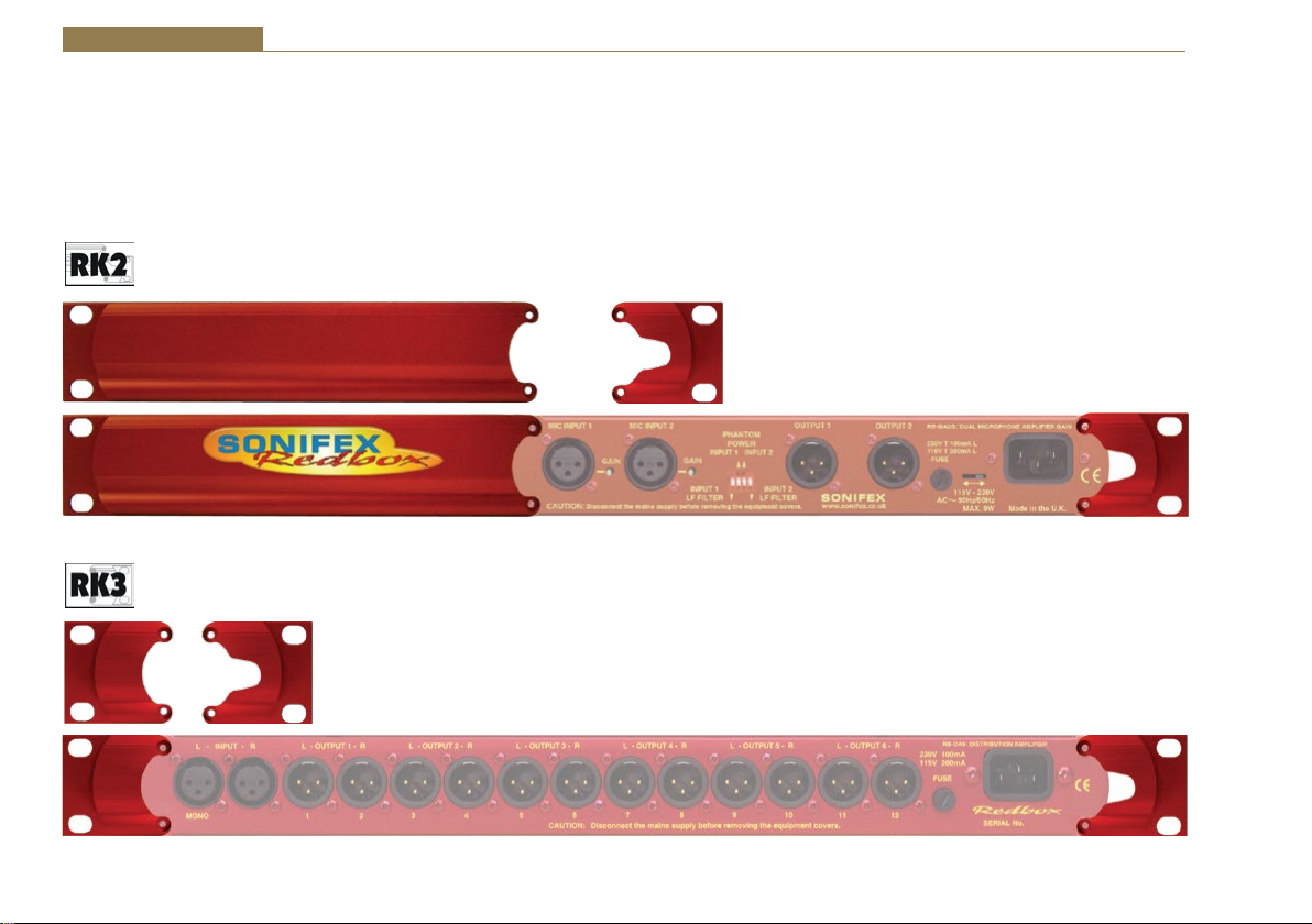
Safety & Installation
They can also be rack-mounted, with either the front, or rear of the Redbox positioned at the front of the rack (Note: this product is front rack-mounted as
standard):
Front Mounting Redboxes: For rack mounting smaller (28cm) units the optional RB-RK1 (Red) or RB-RK1B (Black) kit can be used (which include
4 off M6 panel fixing screws).
Rear Mounting a Redbox: For rear panel mounting you can use either the RB-RK2 (in this case), or RB-RK3, depending on the size of your Redbox.
Fig B: RB-RK2 Small Redbox Rear Rack-mount Kit.
Fig C: RB-RK3 Large Redbox Rear Rack-mount Kit.
vi

1 RB-SD1 Silence Detection Unit
Introduction
Fig 1-1: RB-SD1 Front Panel
The RB-SD1 Silence Detect Unit is a 1U rack mount device used to monitor
an unattended stereo studio feed and in the event of the signal going
“quiet” after a given period the unit will switch through an alternative
stereo audio signal. This signal could be a recorded message (e.g. “normal
service will be resumed”, etc), a feed from a CD player or minidisk machine,
or an alternative recorded program. Controls are provided to start external
equipment and to provide remote status indication.
It has 2 balanced stereo audio inputs with the maximum input level being
+28dBu. Each input is user-defined as either the main source or auxiliary
source and both sources are monitored for failure, each having a remote
failure alarm. In the event of the main source dropping below a pre-set
level for a pre-determined amount of time, the unit will automatically
switch through to the auxiliary signal. The silence detect level is adjustable
between -60dBu and -15dBu in 3dB steps via a 16 position rotary switch on
the rear panel. The silence interval can be adjusted between 2 seconds to
30 seconds in 2 second steps, or, alternatively, set to 2 minutes 5 seconds
also via a 16 position rotary switch on the rear panel. The audio outputs use
stereo professional balanced XLR-3 male connectors.
The unit can operate in 2 modes - automatic or manual. In both modes it
will automatically switch over to the auxiliary source on detecting silence.
When the main signal is again detected it will either return to the main
signal automatically or manually depending on the mode chosen.
Silence Detectors - RB-SD1 1
The RB-SD1 has a number of remote operational features. Remote outputs
provide separate relay contact closures for failure of the main and auxiliary
inputs. You can also control remotely all of the front panel switches for
source selection, mode selection and signal Restore. You can remotely
start and stop another piece of equipment on alarm failure and main signal
return respectively. Also, the longest silence time (2min 5sec) can be set
remotely, which is useful if you are expecting to broadcast a long silence.
The unit can be configured to alarm when either the left or right channel of
the main input source fails, or if the whole stereo signal fails. There are also
options to set the remote start output as momentary or latched, to disable
switching to the auxiliary input on alarming and to increase the gain on the
auxiliary input so that an unbalanced input can be used, for example, from
a domestic minidisc player.
Front panel LED indicators show individually left and right programme and
alarm conditions for both the main and auxiliary inputs. The status of the
source, mode and alarm state are also shown on the front panel with LED
indicators.
Additionally, the RB-SD1 can be programmed for specific applications,
which can be defined on power-up of the unit, e.g. for extended silence
detect times. See page 7 for current additional power-up modes, or
contact Sonifex for further information if you have a particular requirement.
1
1 Silence Detectors - RB-SD1
()
The RB-SD1 has been designed to have a passive signal path through the
main input, so if power to the unit fails, the signal input will still be routed
through to the output. This is essential for applications such as installation
at transmitter sites, where a power failure to the unit should not prevent
the audio input signal from being output to the transmitter.
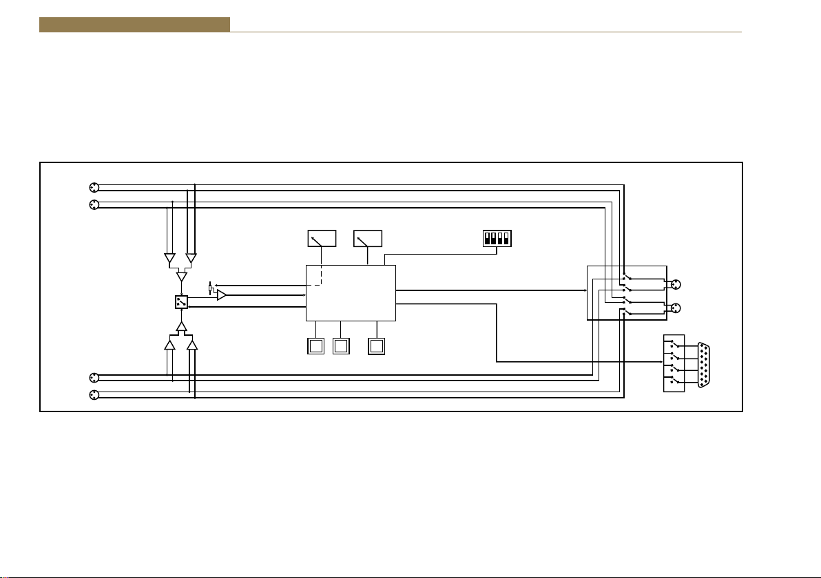
System Block Diagram
Stereo
Input A
Professional
Balanced
Stereo
Input B
Professional
Balanced
Fig 1-2: RB-SD1 System Block Diagram
Left
Right
Left
Right
Summing
Amp
Monitored
Channel Select
Summing
Amp
Digital
Pot
Comparator
Control
A/B
Switch
Control
Reference
Voltage Select
0...9,A...F
Microprocessor
Push
Switch
Mode
Restore
Time Select
0...9,A...F
Push
Switch
Main Channel
Select
Mode Select
Output
Select
Output Select
Default/Power Off
Select Input A
Stereo
Output
Left
Professional
Balanced
Right
15 PIN
Remote
Connector
2

Rear Panel Connections and Operation
A Inputs
B Inputs
Stereo
Outputs
Time
Control
Silence Detectors - RB-SD1 1
Remotes
Connector
Fig 1-3: RB-SD1 Rear Panel
A/B Inputs (Left and Right)
There are four XLR-3 inputs, two for channel A (Left & Right) and another
two for channel B (Left & Right). The XLR 3 pin sockets are used for the
input channels and are electronically balanced. They have the following
connections: Pin 1: Screen.
Pin 2: Phase.
Pin 3: Non-phase.
Outputs
The stereo input consists of two XLR male connectors professionally
balanced with following connections: Pin 1: Screen.
Pin 2: Phase.
Pin 3: Non-phase.
Silence Detect Trigger Level
The trigger level rotary switch (Level) adjusts the level below which silence
detection occurs. This level may be varied from –15dB to -60db in 3db steps
by adjusting the switch, which is accessible on the rear panel.
Level
Control
Mode
Select
Switch 0 1 2 3 4 5 6 7 8 9 A B C D E F
Level
-60 -57 -54 -51 -48 -45 -42 -39 -36 -33 -30 -27 -24 -21 -18 -15
dBu
Silence Detect Interval Control
The silence detect interval rotary switch (Time) adjusts the duration over
which a silence is detected before alarming and ranges from 2-30 seconds
(0 – E in 2 second intervals) with F on the switch being a 2 min 5 second
silence. This maximum time can also be activated or de-activated remotely
via the remote connector.
Switch 0 1 2 3 4 5 6 7 8 9 A B C D E F
Seconds 2 4 6 8 10 12 14 16 18 20 22 24 26 28 30 125
Mode Dip Switch Settings
ON
1
34
2
OFF
1. Stereo/Mono.
2. Remote Start Mode Switch.
3. Professional levels/Consumer levels (Input B).
4. Switch/No switching when alarmed.
3

1 Silence Detectors - RB-SD1
1. Stereo/Mono Switch – The configuration of this defines whether you
want to switch sources when left and/or right channel of the incoming
source go silent.
Switch Description
On
Off
2. Remote Start Mode Switch – This defines whether the remote start
switch is momentary or latched. Used for starting external equipment when
silence is detected.
Switch Description
On
Off
When on, the unit operates in stereo mode, whereby if one
channel goes quiet the unit will switch, and requires both
channels to be present before it switches back.
When off, the unit operates in mono mode. In this mode
the unit will only switch when both channels go quiet, and
requires only one channel to be present before the unit
switches back.
When on, the remote start pin (pin 15) on the remote
connector is pulled low for half a second when the unit
switches to the auxiliary input. (Momentary contact).
When off, the remote start pin on the remote connector is
pulled low when the unit switches over to the auxiliary input
and remains low until the unit switches back to the main
source or, if in manual mode, is restored by the user locally
or remotely. (Latched contact).
3. Professional/Consumer Switch – This allows you to use an unbalanced
piece of equipment as the auxiliary input, by raising the input gain.
Switch Description
On When on, Input B accepts professional balanced signal level.
Off
4. Switch/No Switching in alarm state – This defines whether the unit
switches to the auxiliary input on silence detection.
Switch Description
On
Off
Remotes Connector
Displayed below are the pin connections and descriptions for the remote
connector:
Pin No. Signal I/O Description
Pin 1 Master Alarm Normally Open O
Pin 2 Master Alarm Normally Closed O
Pin 3 Aux. Alarm Normally Open O
Pin 4 Aux. Alarm Normally Closed O
Pin 5 Mode Switch I Momentary make to Pin 8
Pin 6 Mode Indicator O
Pin 7 Restore Switch I Momentary make to Pin 8
When off, Input B accepts consumer unbalanced signal level
and raises the input gain received by 12dB.
When on, if the unit goes into the alarm state the unit
switches to the auxiliary input.
When off, if the unit goes into the alarm state the unit does
not switch to the auxiliary input.
Relay 1 N/O to Pin 9 in
alarm state
Relay 1 N/C to Pin 9 in
alarm state
Relay 2 N/O to Pin 11 in
alarm state
Relay 2 N/C to Pin 11 in
alarm state
Internal Open Collector to
Digital Ground
4

Silence Detectors - RB-SD1 1
Pin 8 Digital Ground - -
Pin 9 Master Alarm Common O
Pin 10 Max Time Whilst Latched I Latched make to Pin 8
Pin 11 Aux. Alarm Common O
Pin 12 +5V O
Pin 13 Source Select Indicator O
Pin 14 Source Select Switch I Momentary make to Pin 8
Pin 15 Remote Start O
N/O to Pin 1, N/C to Pin 2
in alarm state
N/O to Pin 3, N/C to Pin 4
in alarm state
To power up to a
maximum 100mA
Internal Open Collector to
Digital Ground
Internal Open Collector to
Digital Ground
Front Panel Selectors and Indicators
Fig 1-4: RB-SD1 Front Panel
Pins 1 - 4 are for external use to replicate the alarm conditions for the Main
and Auxiliary inputs.
Pins 5 - 7, 13 and 14 are to replicate the switches and indicators for the
source select, mode and restore functions.
Pins 8, 9, 11 and 12 are common or voltage pins.
Pin 10 is to select remotely the maximum silence time (2min 5sec). This
may be useful for the broadcast of Remembrance Day services, or where
you expect a silence of up to 2 minutes to be broadcast. The maximum
silence time is set whilst the contact is latched.
Pin 15 is used to remotely start an external piece of equipment and
operates on audio fail.
Source
Selector
Mode Selector
and Indicator
Alarm
Indicator
5

1 Silence Detectors - RB-SD1
Source Select and Indicator
The normal Main input source is selectable via a push switch accessed via
a hole located on the front panel, or it can be controlled remotely (pins 13
and 14). This allows you to define whether input A, or input B is going to be
your Main audio input. There is an LED to indicate which state the source
select is set:
LED Description
LED On Main source is input A, Aux source is input B
LED Off Main source is input B, Aux source is input A
Note : If the unit is powered off, for example during a black-out, input A
routes through to the output. Therefore if the unit is subject to a power
fail while the main source is set to input B, the unit will output source A.
Mode Selector and Indicator
The Mode Switch defines how the unit should operate during an alarm
condition, when the main audio source returns. There is an option to
allow the device to switch back Automatically or Manually. The mode is
selected by a push switch accessed through a hole on the front panel with
a corresponding LED to represent its state, or it can be controlled remotely
(pins 5 and 6).
LED Description
Automatic Mode – During an alarm condition when the
LED On
LED Off
LED
Flashing
Main and Aux Indicators
On the front panel there are four Main indicators and four Aux indicators.
Each left/right channel has a Program Content and Alarm Status indicator.
The Program Content Indicator represents the input signal level for that
channel and the Alarm Status LED indicates when the channel has dropped
below the threshold for longer than the time selected.
Both the Main and Aux inputs are continuously monitored so that you can
check that your backup signal is operating correctly, as well as your main
input source.
Note: Although one channel of the stereo input may have alarmed,
the main alarm may not be set, due to the setting of the Stereo/Mono
Dipswitch.
Alarm Indicator
The Alarm indicator situated on the front panel is used to display the alarm
status of the Main input. Its operation is dependant on the selected mode.
When in stereo mode the unit alarms on a single main channel timeout,
and in mono, alarms on both main channels timing out. The unit exits the
alarm state on the return of the main source signal, depending on the
setting of the Stereo/Mono Dipswitch. The alarm indicator is remotely
indicated on pins 1 and 2 of the remotes connector.
main source returns, it is switched back automatically,
although there must be a continuous signal present for two
seconds before it switches.
Manual Mode – When the alarm condition is reached, the
LED begins
to flash.
Manual Mode – The main audio has returned after an alarm
condition. To switch to the main source, push the Restore
button (or control it remotely).
6

Silence Detectors - RB-SD1 1
Restore Button
The restore button is used for restoring the main source signal when the
unit is operating in Manual Mode. When the main source signal returns
after it has timed out, the Mode LED flashes, indicating that the source
signal can be restored. When the Restore button is pressed the main source
returns. This can be remotely controlled using pin 7 of the
remotes connector.
Additional Modes
An option to set the unit in different modes of operation is available and
is selectable when the unit is powered on. The current available modes of
operation are as follows:
Normal Mode is as described previously for normal machine power-up.
Remote Stop Mode operates as follows. When the main source returns
from an alarmed state, pin 4 on the remote connector (Aux Alarm) closes
to Pin 11 (Aux Alarm Common) for half a second. (Note: this will only occur
when the Remote Start Mode Switch is set on (page 4) and whilst in
Remote Stop Mode the Aux alarm is not available to indicate the presence
of audio on the auxiliary input).
Remote Alarm Set Mode operates as follows. When the RESTORE pin on
the remote connector (pin 7) closes to the DIGITAL GROUND pin on the
remote connector (pin 8) the unit will immediately enter an alarmed state
and switch to the auxiliary input. This alarm state is continued until the
RESTORE pin opens to the DIGITAL GROUND pin. After this the unit will
switch back to the main input when audio is present.
NOTE: When operating in manual mode, restoration of output from the
main input is only available via the front panel restore switch. All other
functions operate as normal.
Signal Detection Mode In this mode the three controls, source, remote
source, mode, remote mode, restore and remote restore have no effect.
The count in time for the signal detection is zero, i.e. as soon as signal is
detected on an input the relevant relay will switch. The relays operate the
same as in normal mode, i.e. when audio is detected on the main input, pin
1 on the remote connector closes to pin 9. When audio is lost on the main
input, pin 2 on the remote connector closes to pin 9. All other functions
operate as with normal mode.
Timeout x 2 Mode. In this mode, the timeout selection is multiplied by
two (see table on the following page), except for the max time selection
(position F on the time rotary encoder). All other functions operate as
normal.
Switch 0 1 2 3 4 5 6 7 8 9 A B C D E F
Seconds 4 8 12 16 20 24 28 32 36 40 44 48 52 56 60 125
Force Main Mode. In this mode only the remote mode control input has
any effect. When this control input is active (low) the output is forced to
input B (the master input) regardless of whether audio is present. The
unit operates in auto mode and with input B as the master input. All other
functions operate as with normal mode.
Emergency Program Override Mode. In this mode all alarm LEDs are
illuminated whenever the main input is active. This is to indicate that the
emergency paging program is active on the main input. When the paging
program goes silent, the unit will revert back to the aux. input and all the
alarm LEDs will switch off. The front panel source button is disabled. All
other functions operate as normal.
Detection Enable/Disable Mode. In this mode the silence detection can be
disabled and enabled remotely. The front panel and remote source select
controls are used to enable or disable the Silence Detection feature.
Front panel Source indicator on = Silence Detection enabled
Front panel Source indicator off = Silence Detection disabled
7

1 Silence Detectors - RB-SD1
The front panel source select button toggles this state, while the remote
Source control (Pin 14 on the remote connector) can only ENABLE Silence
Detection. Pin 10 on the remote connector is used to DISABLE Silence
Detection. When the unit powers up Silence Detection is always enabled.
The remote source select indicator (Pin 13 on the remote connector) is
enabled when Silence Detection is disabled. In this mode input A is always
the Main input and input B is always the Aux input. Since the front panel
and remote source selection controls are disabled, source selection is not
allowed in this mode. The Aux alarms are masked for both front panel
indicators and remote alarm relay, for as long as the main input is present.
Return Time Set Mode. In this mode, the unit operates as normal, except
that during power up the return time delay can be programmed. The
return time delay is the amount of time, during an alarm condition, that
the unit takes to switch from the Aux to Main input once audio is presented
to the Main input. To set the return time, immediately after the unit is
switched on, press and hold the MODE switch. While the MODE switch is
pressed set the TIME rotary switch to required setting (see below). When
finished, release the MODE switch, and the unit will start operating within
a few seconds. Remember to return the TIME rotary switch to the required
setting.
Rotary Setting 0 1 2 3 4 5 6 7 8 9 A B C D E F
Seconds 0 2 4 6 8 10 12 14 16 18 20 22 24 26 28 120
To Set the Additional Modes:
Apply power to the unit, and while the front panel ALARM LED is flashing,
press and hold the RESTORE button. The MAIN and AUX PROG and ALARM
LEDs will flash alternately - these are used to indicate the selected mode.
The SOURCE LED will also alternate to show the mode bank that is currently
selected.
Note: For RB-SD1 units with serial number greater than RB031084, the
SOURCE LED is used to show the bank of the selected mode. For serial
8
numbers before this, the SOURCE LED is not used. Contact Sonifex Ltd
if you want to upgrade your RB-SD1 unit to the latest version to take
advantage of a new mode.
To select the particular mode, release the RESTORE button when the
corresponding LED below is on. After the button is released the unit will
start working after five seconds. You only have to do this once as the
mode is stored in non-volatile memory and you will only need to repeat
this procedure if you wish to select a different mode. Each time the unit is
powered on, the selected mode is visible by checking which LED is on:
Bank 0 (SOURCE LED off) Mode Selected
MAIN LEFT PROG LED on = Normal Mode
MAIN LEFT ALARM LED on = Remote Stop Mode
MAIN RIGHT PROG LED on = Remote Alarm Set Mode
MAIN RIGHT ALARM LED on = Signal Detection Mode
AUX. LEFT PROG LED on = Timeout Times 2 Mode
AUX. LEFT ALARM LED on = Force Main Mode
AUX. RIGHT PROG LED on = Emergency Program Override Mode
AUX. RIGHT ALARM LED on = Detection Enable/Disable Mode
Bank 1 (SOURCE LED on)
MAIN LEFT PROG LED on = Return Time Set Mode
MAIN LEFT ALARM LED on = Reserved
MAIN RIGHT PROG LED on = Reserved
MAIN RIGHT ALARM LED on = Reserved
AUX. LEFT PROG LED on = Reserved
AUX. LEFT ALARM LED on = Reserved
AUX. RIGHT PROG LED on = Reserved
AUX. RIGHT ALARM LED on = Reserved

Technical Specifications RB-SD1
Silence Detectors - RB-SD1 1
Audio Specifications
Maximum Input Level: +28dBu
Input Impedance: > 100kΩ balanced
Maximum Output Level: +28dBu
Output Impedance: As input, except when using unbalanced
auxiliary input where output impedance < 50Ω
Frequency Response: 20Hz to 20kHz ±0.1dB
Gain: +12dB (for unbalanced input B – optional)
Noise: <-87dB, unity gain, ref +8dBu output for
unbalanced input.
Distortion: As input for balanced input, <0.05% ref +8dBu
output for unbalanced input.
Connections
Inputs (Main & Auxiliary): 4 x XLR 3 pin female (balanced, auxiliary can
be unbalanced)
Output: 2 x XLR 3 pin male (balanced)
Remotes: 15 way D-type plug
Power: Filtered IEC, 110-120V, or 220-240V switchable,
fused, 6W maximum
Fuse Rating: Anti-surge fuse 100mA 20 x 5mm (230VAC)
Anti-surge fuse 250mA 20 x 5mm (115VAC)
Rear Panel Controls
Alarm Threshold: -15dBu to -60dBu in 3dB steps via rotary switch
Silence Detect Duration: 2 sec to 30 sec in 2 second intervals and 125
second option via rotary switch
Detection Type: Mono or stereo, via dipswitch
Silence Switch Defeat: Disable/enable silence switching, via dipswitch
Remote Start Mode: Latched or momentary, via dipswitch
Front Panel Controls and Indicators
Controls: Source select, mode select and restore
Indicators: Program and alarm indicators for left and right
source for both main and auxiliary channels
Source, mode and restore LEDs
Equipment Type
RB-SD1: Silence detection unit
Physical Specifications
Dimensions (Raw): 48cm (W) x 10.8cm (D) x 4.2cm (H) (1U)
19” (W) x 4.3” (D) x 1.7” (H) (1U)
Dimensions (Boxed): 53cm (W) x 20.5cm (D) x 6cm (H)
21” (W) x 8” (D) x 2.4” (H)
Weight: Nett: 1.4kg Gross: 2.0kg
Nett: 3.1lbs Gross: 4.4lbs
9

2 Silence Detectors - RB-SD1IP
2 RB-SD1IP Silence Detection Unit With Ethernet & USB
Introduction
Fig 2-1: RB-SD1IP Front Panel
The RB-SD1IP Silence detection unit is an upgraded version of the existing
Sonifex RB-SD1. The unit is a 1U rack mount device used to monitor an
unattended stereo studio feed and in the event of the signal going “quiet”
after a given period the unit will switch through an alternative stereo audio
signal. This signal could be a recorded message (e.g. “Normal service will
be resumed”, etc), a feed from a CD or minidisc player, or an alternative
recorded program. Controls are provided to start external equipment and to
provide remote status indication.
The RB-SD1IP has several new features in addition to the functionality of
the standard RB-SD1.
Ethernet connectivity provides the ability to set up and control the unit via
a browser based Graphical User Interface (GUI). The network capabilities
allow the user to more finely control silence Levels (-60dBu to 0dBu in 3dBu
steps) and Time delays (1 second to 24 hours), you can also remotely lock/
unlock the front panel controls on the unit and choose to use either the
hardware configured settings or web based settings. In addition to the front
panel LEDs the GUI home page also offers a real time view of signal levels
and alarm statuses.
Also using the GUI, left and right channels can be treated independently,
remote relay triggers can be configured as one of many events including
the new GPI pins. You can also choose to lock/unlock the use of the remote
pins to control the unit. Firmware updates can also be performed using the
web GUI.
10
SNMP V1 is implemented so that the unit can be monitored by existing
Network Management Systems (NMS). The addition of 6 extra GPI pins to
the rear panel, allows customisable functionality, including the use of the
RB-SD1IP network interface to generate SNMP Traps on behalf of other,
non-networked, hardware.
The RB-SD1IP has been fitted with a USB interface on the front panel and
can act as a host in two ways. Firstly the USB port can be used to upgrade
the firmware on the unit from a USB flash drive. Such a drive can also hold
a pre-recorded message which the unit can play out in the event that both
main and auxiliary signals both fall silent.
As on the standard RB-SD1, the RB-SD1IP has 2 balanced stereo audio
inputs with a maximum input level of +28dBu. Each input is user-defined as
either the main source or auxiliary source and all channels are monitored
for failure. In the event of the main source dropping below a pre-set level
for a pre-determined amount of time, the unit will automatically attempt
to switch through to a valid auxiliary signal. The silence detect level is
adjustable between -60dBu and -15dBu in 3dB steps via a 16 position rotary
switch on the rear panel. The silence interval can be adjusted between 2
seconds to 30 seconds in 2 second steps, or, alternatively, set to 2 minutes
5 seconds also via a 16 position rotary switch on the rear panel. More fine
control of the detection levels and times can be set using the web browser
based GUI. The audio inputs and outputs use stereo professional balanced
XLR-3 connectors.

Silence Detectors - RB-SD1IP 2
The unit has 2 operational modes for restoring a signal - automatic or
manual. In both modes the unit will automatically switch over to a valid
auxiliary source upon detecting silence. When a valid main signal returns
it will either restore to the main channel automatically or manually
depending on the mode selected.
The RB-SD1IP has a number of remote operational features. Rear panel
remote outputs provide separate relay contact closures for failure of the
main and auxiliary inputs. You can also remotely control all of the front
panel switches for source selection, mode selection and signal Restore.
You can remotely start and stop another piece of equipment on alarm
failure and main signal return respectively. A silence time of 2 minutes
and 5 seconds can be set remotely, which is useful if you are expecting to
broadcast a long silence.
The unit has three signal type operational modes – Stereo, Mono and
Independent. In stereo mode, the unit will alarm if either the left or right
channel falls silent. In mono mode the unit will only alarm if both left and
right channels fall silent. In independent mode the unit can be configured
to operate as a 2 channel mono silence detector, alarming and switching
the two input channels independently. There are also options to set the
remote start output as momentary or latched, to disable switching to the
auxiliary input on alarming and to increase the gain on the auxiliary inputs
so that unbalanced sources can be used, for example, from a domestic flash
memory/USB player.
Front panel LED indicators show individually left and right programme
status and alarm conditions for both the main and auxiliary inputs. The
status of the source, mode and alarm state are also shown on the front
panel with LED indicators.
The RB-SD1IP has been designed to have a passive signal path through the
main input, so if power to the unit fails, the signal input will still be routed
through to the output. This is essential for applications such as installation
at transmitter sites, where a power failure to the unit should not prevent
the audio input signal from being output to the transmitter.
11

2 Silence Detectors - RB-SD1IP
System Block Diagram
Left
Stereo
Input A
Right
Left
Stereo
Input B
Right
Ethernet
Reset
USB
Summing
Amplifiers
Consumer Gain Select
0-9D-F
Level
Select
0-9D-F
Time
Select
Mode
Select
ADC
Microprocessor
Output Select
GPI Socket
USB Audio
Output Select
Remote Relay Control
9 Way
Stereo
Outputs
Left
Balanced
Right
15 Way
Remotes Plug
Fig 2-2: RB-SD1IP System Block Diagram
12
Mode
Button
Restore
Button
Source
Select
Button

Silence Detectors - RB-SD1IP 2
Rear Panel Connections and Operation
A Inputs
Fig 2-3: RB-SD1IP Rear Panel
B Inputs
Stereo
Outputs
A/B Inputs (Left and Right)
There are four XLR-3 inputs, two for channel A (Left & Right) and another
two for channel B (Left & Right). The XLR 3 pin sockets are used for the
input channels and are electronically balanced. They have the following
connections: Pin 1: Screen.
Pin 2: Phase.
Pin 3: Non-phase.
Outputs
The stereo output consists of two XLR male connectors professionally
balanced with following connections: Pin 1: Screen.
Pin 2: Phase.
Pin 3: Non-phase.
Silence Detect Trigger Level
The Level rotary switch adjusts the level below which silence detection
occurs. This level may be varied from –15dB to -60db in 3db steps by
adjusting the switch according to the following table:
GPI/O
Socket
Remote
Plug
Ethernet Fuse
IFC
Power
Level
Control
Mode
Time
Control
Inlet
Switch 0 1 2 3 4 5 6 7 8 9 A B C D E F
Level dBu -60 -57 -54 -51 -48 -45 -42 -39 -36 -33 -30 -27 -24 -21 -18 -15
Silence Detect Interval Control
The silence detect interval rotary switch (Time) adjusts the duration over
which a silence must persist before alarming the unit. The time ranges from
2 to 30 seconds (0 – E in 2 second intervals) with F on the switch being a
2 min 5 second silence. This maximum time can also be activated or deactivated remotely using the remote connector.
Switch 0 1 2 3 4 5 6 7 8 9 A B C D E F
Seconds 2 4 6 8 10 12 14 16 18 20 22 24 26 28 30 125
Note: Better control of the Silence Detect Level and Interval are available
by using the Webserver built into the RB-SD1IP. See section 4 for more
information.
Mode DIP Switch Settings
ON
1
34
2
OFF
1. Stereo/Mono.
2. Remote Start Mode Switch.
3. Professional levels/Consumer levels (Input B).
4. Switch/No switching when alarmed.
13

2 Silence Detectors - RB-SD1IP
1. Stereo/Mono Switch – The configuration of this defines whether you
want to switch sources when left and/or right channel of the incoming
source go silent.
Switch Description
On When on, the unit operates in stereo mode, whereby if one
channel falls silent the unit will switch, and requires both channels
to be present before it switches back.
Off When off, the unit operates in mono mode. In this mode the unit
will only switch when both channels go quiet, and requires only
one channel to be present before the unit switches back.
Note: the Independent channel option can only be configured using the
web based GUI not by using physical rear panel controls.
2. Remote Start Mode Switch – This defines whether the remote start
switch is momentary or latched. Used for starting external equipment when
silence is detected.
Switch Description
On When on, the remote start pin (pin 15) on the remote connector is
pulled low for half a second when the unit switches to the auxiliary
input. (Momentary contact).
Off When off, the remote start pin on the remote connector is pulled
low when the unit switches over to the auxiliary input and remains
low until the unit switches back to the main source or, if in
manual mode, is restored by the user locally or remotely. (Latched
contact).
3. Professional/Consumer Switch – This allows you to use an unbalanced
piece of equipment as the auxiliary input, by raising the input gain.
Switch Description
On When on, Input B accepts professional balanced signal level.
Off When off, Input B accepts consumer unbalanced signal level and
raises the input gain received by 8dB.
4. Switch/No Switching in Alarm State – This defines whether the unit
switches to the auxiliary input upon silence detection.
Switch Description
On When on, if the unit goes into the alarm state the unit switches to
the auxiliary input.
Off When off, if the unit goes into the alarm state the unit does not
switch to the auxiliary input.
Remote Alarms Connector
Displayed below are the pin connections and descriptions for the remote
plug connector:
Pin No. Signal I/O Description
Pin 1 Digital Ground - -
Pin 2 Restore Switch I Momentary make to Pin 1
Pin 3 Mode Indicator O Internal Open Collector to Digtal
Ground
Pin 4 Mode Switch I Momentary make to Pin 1
Pin 5 Relay 2 Normally Closed I/O Relay 2 N/C to Pin 14
Pin 6 Relay 2 Normally Open I/O Relay 2 N/O to Pin 14 Ground
Pin 7 Relay 1 Normally Closed I/O Relay 1 N/C to Pin 15
Pin 8 Relay 1 Normally Open I/O Relay 1 N/O to Pin 15
Pin 9 Remote Start O Internal Open Collector to Digital
Ground
Pin 10 Source Select Switch I Momentary make to Pin 1
Pin 11 Source Select Indicator O Internal Open Collector to Digital
Ground
Pin 12 +5V O To power up to a maximum
200mA
14

Silence Detectors - RB-SD1IP 2
Pin 13 Relay 2 Common I/O N/O to Pin 6, N/C to Pin 5
Pin 14 Max Time Whilst Latched I Active Low make to Pin 1
Pin 15 Relay 1 Common I/O N/O to Pin 8, N/C to Pin 7
Please note: Pins 5, 6, 7, 8, 13 and 15 are for external use to break/make
contacts in response to a configurable event in the unit. For example
these relays can be used to replicate the alarm conditions for the Main
and Auxiliary inputs. Options for these relays may be configured using the
web based GUI. The operation of Relay 1 and Relay 2 can be re-configured
through the Configuration>Remotes web page.
By default Relay 1 is set as the Main alarm and will alarm on either Main
left or Main right - in the alarm state pin 8 closes to pin 15 and pin 7 is
open. Relay 2 is set as the Aux alarm and alarms on Aux left or Aux right -
under the alarm condition pin 6 closes to pin 14 and pin 5 is open.
Pins 2, 3, 4, 10 and 11 are to replicate the switches and indicators for the
Source Select, Mode and Restore functions.
Pin 11 can be configured through the web GUI to indicate either the main
source selection or the current output signal source.
Note: The remote source select, pin 10, may be held low in order to force
the unit to route stereo input source B to the outputs.
Pins 1 & 12 are Ground and +5V respectively and can be used to source up
to 200mA of current to power external circuitry such as LED indicators or
relays.
Pin 14 is to select remotely a silence time of 2 minutes and 5 seconds. This
may be useful for the broadcast of Remembrance Day services, or where
you expect a silence of up to 2 minutes to be broadcast. The maximum
silence time is set whilst the contact is latched.
Pin 9 is used to remotely start an external piece of equipment and operates
on audio fail.
GPI/O Connector
There are 6 GPI pins available on a 9 way female D-type connector located
above the Remote Alarms Connector. These pins have been included to
provide more customised behaviour of the RB-SD1IP which could enable
non-networked hardware to generate alarms for an existing Network
Management System by using the network interface of the RB-SD1IP.
Currently each of the GPI pins can be used to trigger one or both of
the relays available to the Remote Alarms Connector. Each GPI can also
generate SNMP traps to follow pin activity.
Power and ground connections are available on this connector from the
same source as the 200mA +5V fused supply on the Remotes connector.
Pin No. Signal I/O Description
Pin 1 GPI 1 I General Purpose Input 1
Pin 2 GPI 3 I General Purpose Input 3
Pin 3 GPI 5 I General Purpose Input 5
Pin 4 Digital Ground - Ground Return For External Circuits
Pin 5 +5VD Fused - 5V Supply Pin to Power External Circuits
Pin 6 GPI 2 I General Purpose Input 2
Pin 7 GPI 4 I General Purpose Input 4
Pin 8 GPI 6 I General Purpose Input 6
Pin 9 Digital Ground 7 Ground Return for External Circuits
Ethernet Connector
The unit supports 10/100 Mbps Ethernet via a standard RJ45 connector.
The Green LED shows link status/activity and the Amber LED indicates
connection speed (On = 100 Mbps, Off = 10 Mbps).
A Webserver is built into the RB-SD1IP to allow easier configuration and
remote operation.
15

2 Silence Detectors - RB-SD1IP
Front Panel Selectors and Indicators
Power
LED
Reset
Button
USB
Socket
Main
Indicators
Fig 2-4: RB-SD1IP Front Panel
Power Indicator
A single red LED confirms the presence of an active power supply to the
unit.
Reset Button
The recessed reset button allows you to perform a hardware reset on the
unit without powering down.
USB Port
The USB port enables the unit to act as a host for low power mass storage
devices (such as flash drives) which are formatted to either FAT or FAT32.
Such devices may be used for the playback of audio files.
The USB functionality is configured using the browser based GUI and allows
you to play out wave (.wav) files in the event of both the Main and Auxiliary
sources falling silent. The currently supported file format is .wav extensions
in PCM 16 bit Stereo encoding.
The unit supports the following sample rates: 8 kHz, 11.025 kHz, 12 kHz, 16
kHz, 22.050 kHz, 24 kHz, 32 kHz, 44.1 kHz, 48 kHz
Only files located in the root directory of the USB device will be available
for playback. The unit supports a playlist in the form of an ordered list of
filenames delineated by a new line.
16
Aux
Indicators
For example:
Track_05.wav
Track_01.wav
03_Song.wav
Melody.mp3
customer_message.wav
The playlist file should be designated “playlist.txt” or “playlist.m3u” and
placed in the root directory with the audio files. Any files in the list which
are invalid (such as the .mp3 in the above example) or not present will be
ignored. If a playlist is not present then the audio files will be played out in
the order of their creation on the USB device.
Note: It is recommended that files of a single sample rate range are used
in order to avoid a small delay (up to 3 seconds) between the playback of
tracks with sample rates in different frequency ranges.
The USB audio playback feature can be remotely enabled or disabled using
the GUI. Other USB audio options include: Default Sample Rate Selection,
Track Recall, Looped Playback and SNMP Trap Generation.
Default Sample Rate:
This option sets up the system clock to be ready to play out files with a
sample rate from a specific frequency range. For example; if your USB
Source Select
Switch and
Indicator
Auto/Manual Mode
Switch and Indicator
Restore Button
and Alarm
Indicator

Silence Detectors - RB-SD1IP 2
device contains files at a sample rate of 24 kHz, set the default sample rate
to 48 kHz range, which also supports the subfrequencies 12kHz & 24kHz, to
ensure the unit always boots up ready to play at the correct clock frequency.
Track Recall:
When this option is disabled, every time USB audio is routed to the output,
the playback will begin from the first available file. When this option is
enabled the unit will remember the previous track it was playing out from
USB and upon USB audio being routed to the output, playback will begin from
the start of the next available file. Note that Track Recall will be lost when the
unit is powered down, or when the USB device is removed.
Looped Playback:
When enabled, this option will play all valid audio files on the USB device in a
loop whenever USB audio is route to the output. When this option is disabled
the audio files on the USB device will only be played through once, per
instance, of the USB audio being routed to the output.
SNMP Trap Generation:
The unit can generate SNMP Traps to inform a Network Management System
(NMS) that a USB device has been plugged into, or unplugged from the front
of the unit.
Main and Aux Indicators
On the front panel there are four Main indicators and four Aux indicators.
Each left/right channel has a Program Content and Alarm Status indicator. The
Program Content Indicator represents the input signal level for that channel
and the Alarm Status LED indicates whether the channel has dropped below
the threshold for longer than the time selected.
Both the Main and Aux inputs are continuously monitored so that you can
check that your backup signal is operating correctly, as well as your main
input source.
Note: Although one channel of the stereo input may have alarmed, the main
alarm may not be set, due to the setting of the Stereo/Mono Dipswitch.
Source Select and Indicator
The preferred Main input source is selectable via a recessed push button
switch on the front panel, or it can be controlled remotely (pin 10) and from
the GUI. This allows you to define whether input A, or input B is going to
be the Main audio input. There is an LED to indicate which state the source
select is in:
LED Description
LED On Main source is input A, Aux source is input B
LED Off Main source is input B, Aux source is input A
The GUI can be used to configure the source select LED to indicate the
current input which is being routed to the output. In this case:
LED Description
LED On Input A is being routed to the output
LED Off Input B is being routed to the output
LED Flashing USB Audio is being routed to the output
Note: If the unit is powered off, for example during a black-out, input A
routes through to the output. Therefore if the unit is subject to a power fail
while the main source is set to input B, the unit will output source A.
Auto/Manual Mode Selector and Indicator
The Auto/Manual Mode Switch defines how the unit should operate during
an alarm condition, when the main audio source returns. There is an option
to allow the device to switch back Automatically or Manually. The mode is
selected by a push switch accessed through a hole on the front panel with a
corresponding LED to represent its state, it can be controlled remotely (pins
3 and 4) or by using the GUI.
17

2 Silence Detectors - RB-SD1IP
LED Description
LED On Automatic Mode – During an alarm condition when the
main source returns, it is switched back automatically,
although a valid signal must persist for at least the
configured Restore Time period.
LED Off Manual Mode – the LED will begin to flash once a valid
main signal is detected, indicating that manual restore can
now be performed.
LED Flashing Manual Mode – The main audio has returned after an
alarm condition. To switch to the main source, push the
Restore button (or control it remotely).
Note: When using Independent Channels in Manual Mode you will need to
press restore once for each channel.
Restore Alarm Indicator
The Restore Alarm Indicator situated on the front panel is used to display
the alarm status of the Main input. Its operation is dependent on the
selected mode (See Mode DIP Switch Settings):
• Stereo mode - the unit alarms on a single main channel timeout.
• Mono mode - alarms on both main channels timing out.
The unit exits the alarm state on the return of the main source signal,
depending on the setting of the Stereo/Mono Dipswitch.
Restore Button
The Restore button is used for restoring the main source signal when the
unit is operating in Manual Mode. When the main source signal returns
after it has timed out, the Mode LED flashes, indicating that the source
signal can be restored. When the Restore button is pressed the main
source returns. This can be remotely controlled using pin 2 of the remotes
connector. There is also a restore button present on the web based GUI.
Reset to Defaults
It is possible to reset the unit to default configuration settings, including
network settings, from the front panel. To perform a full reset you must
press and hold the Restore button whilst resetting or power cycling the
unit.
Physical Configuration
It is possible to force the unit to use physical configurations (rear panel dip
& hex switches) rather than the browser based GUI settings. To do this you
must press and hold the Source Select button whilst resetting or power
cycling the unit.
Note: When switching to physical configuration from webpage
configuration, the operation of the unit could change significantly.
Boot Mode
In the unlikely event that the RB-SD1IP becomes inoperable due to
corruption of the main firmware, you can force the unit into Boot Mode.
To do this you must hold down both the Source Select and Mode buttons
whilst resetting or power cycling the unit. To indicate that Boot Mode is
active the Source, Mode and Restore LEDs will flash. A unit in “Boot Mode”
can be discovered and updated through the webpage in the same way as
for main firmware.
Additional Modes
The original RB-SD1 offered the option to configure the unit into various
additional modes of operation. The RB-SD1IP offers these options through a
webserver based GUI.
18

Silence Detectors - RB-SD1IP 2
RB-SD1IP Network Discovery and Webserver
In addition to any physical controls the RB-SD1IP has a built in webserver
which can allow you to control and configure the unit remotely through
a web browser. The webpage interface also enables you to view status
information, alter network settings, and update product firmware.
The RB-SD1IP network interface employs Zeroconf networking, meaning
that it supports DHCP, AutoIP and MDNS-SD using Bonjour. We provide a
free application available for download from our website (www.sonifex.
co.uk/technical/software) to facilitate the discovery and use of Sonifex
network enabled hardware, see below for more information.
Connecting to the unit: Connecting to the webpage interface is as simple as
typing the IP address of the unit into the address bar of a web browser on a
PC connected to the same network.
DHCP
The RB-SD1IP will have DHCP and AutoIP enabled by default, if your
network has a DHCP server then the unit will be assigned an IP address
which can be found easily by using the Sonifex service discovery application,
or by contacting your network administrator. The nature of DHCP means
that the unit is not guaranteed to maintain a fixed IP address each time it
is reconnected to the network. See the section on static network settings
below for information on how to fix the IP address of the unit.
AutoIP
If your network does not support DHCP or it is disabled, then with AutoIP
enabled the unit will assign itself an IP address from the AutoIP range
(169.254.1.0 to 169.254.254.255). Once an AutoIP address has been
assigned you will need to connect the unit directly to a PC using an Ethernet
cable. Ensure that the PC has dynamic addressing enabled and you will be
able to use the Sonifex discovery application on this mini network to access
the webpage interface.
Static Network Settings
Accessing the webpage interface allows you to configure the network
settings as you like. To give the unit a fixed network address, enter
appropriate static details and disable both DHCP and AutoIP. The unit
will now apply the static network settings whenever it is connected to a
network.
MDNS-SD and Bonjour
Bonjour is a hardware discovery service developed by Apple and as such
it is natively supported by Apple devices and operating systems. Bonjour
for Windows is available, go to our website (www.sonifex.co.uk/technical/
software) or other download stores and download the appropriate version
for your operating system.
On a Bonjour enabled device or system, you can connect to a unit using
only its hostname. By default the hostname for the RB-SD1IP will be the
hardware ID appended by the unique serial number of the unit:
[Hardware ID] – [Serial No.]
RB-SD1IP-654321
To connect to a unit using Bonjour you can simply discover and launch
the webpage interface from the Sonifex service discovery application.
Alternatively you can simply type the hostname appended by the local
domain name into the address bar of your web browser, for the example
above you would enter the following:
RB-SD1IP-654321.local.
The hostname is independent of the IP address and this means that the
unit can always be discovered and accessed in this way, regardless of which
IP address it has been assigned by a DHCP server. The hostname can be
changed to make it more memorable or descriptive of an implementation,
however, conflicting names should be avoided.
19

2 Silence Detectors - RB-SD1IP
Sonifex Service Discovery App
This is a free download for Windows, available from our website (www.
sonifex.co.uk/technical/software). This application uses Bonjour to locate
networked hardware and discover what services it has to offer. On a device
or system running Bonjour you can discover Sonifex hardware and launch
the webserver interface if available. The application also offers legacy
discovery for systems which do not support Bonjour or for Sonifex hardware
which is not running MDNS-SD.
Fig 2-5: Sonifex Service Discovery - Bonjour Page Fig 2-6: Sonifex Service Discovery - Legacy Discovery Page
20
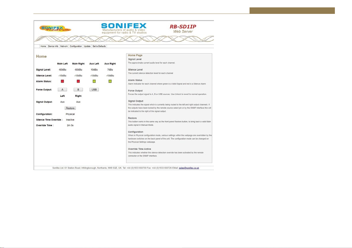
Fig 2-7: RB-SD1IP Screenshot of the Webserver Home Page
The web based GUI has a menu bar that allows you to navigate through various pages to
configure different aspects of the unit. Each page follows the same standard layout as the
Home page, with current status/configuration settings on the left and tooltip explanations
in the box on the right. The page footer contains contact details for Sonifex Ltd.
Home Page
Signal Level
The approximate current audio level for each channel.
Silence Detectors - RB-SD1IP 2
Silence Level
The current silence detection level for each channel.
Alarm Status
Alarm Indicator for each channel where green is a Valid Signal
and red is a Silence Alarm.
Force Output
These three buttons allow the user to force the output signal
to either the A, B or USB inputs. When the output signal is
forced, an unlock button is visible. This will revert the unit
back to normal operation.
Signal Output
This indicates the signal which is currently being routed to
the left and right output channels. If the outputs have been
locked by the remote source select pin or by the SNMP
interface this will be indicated to the right of the signal
output.
Restore
This button works in the same way as the front panel Restore
button, to bring back a valid Main audio signal in Manual
Mode.
Configuration
When in Physical configuration mode, various settings within
the webpage are overridden by the hardware switches on
the back panel of the unit. The configuration mode can be
changed on the Physical Settings webpage.
2 Minute Silence
This indicates whether the 2 minute silence detection
override has been activated by the remote connector or the
SNMP interface.
21

2 Silence Detectors - RB-SD1IP
Device Information
This page shows general information about the
connected RB-SD1IP.
Fig 2-8: RB-SD1IP Screenshot of the Webserver Device Page
22

Fig 2-9: RB-SD1IP Screenshot of the Webserver Network Settings Page
Network Settings
Host Name
The Host Name for this unit is used for Multicast DNS Service Discovery. The default Host Name is
the unit Hardware Type, appended with the unique Serial Number.
Silence Detectors - RB-SD1IP 2
IP Address
Please enter the static IP Address that you wish
to assign to this unit. The address must be in the
correct form, the default address is: 192.168.0.100
Netmask
Please enter the Netmask of the network you
wish to connect to. The default subnet mask is:
255.255.255.0
Gateway Address
Please enter the Gateway Address of your router.
The default gateway address is: 192.168.0.149
Dynamic Addressing
Enable Dynamic Addressing or disable to force the
use of the static network settings entered above.
When enabled, DHCP and AutoIP are used, the
unit will use AutoIP until DHCP server is detected.
HTTP Port
Configures the port which the webserver listens
on. This can be set to port 80, or a number
between 1024 and 65535. The unit must be
restarted for this setting to take effect.
Password
It is possible to setup password access to the unit’s
webserver. To add a password, simply enter a
new password in the New Password entry box and
re-type it in the Retype Password entry box. The
password should be between 4 and 8 characters
in length and contain only letters and numbers.
After submission, the user will be required to
enter this password to gain access to the device.
The username is always admin.
23

2 Silence Detectors - RB-SD1IP
Fig 2-10: RB-SD1IP Screenshot of the Webserver Level & Time Settings Page
Configuration : Level & Time Settings
Select the channel you wish to configure from the drop down list and change its settings as
required. Once you have configured all channels, hit submit.
Silence Level
Select the desired audio level to be treated as
silence.
Silence Time
Enter the desired length of time for which the signal
must be below the selected Silence Level, before an
alarm is triggered. (Format; Hrs : Mins : Secs)
Restore Time
Enter the desired length of time for which a signal
above the selected Silence Level must persist,
before an alarm state is cancelled. (Format; Hrs :
Mins : Secs)
Alarm / Valid Traps
Choose to enable or disable SNMP Trap generation
following changes in alarm state for each channel.
The Alarm Trap will be generated when the signal
status becomes alarmed. The Valid Trap will be
generated when the signal status changes from
alarmed back to normal. The destinations for traps
can be configured on the SNMP configuration page.
Line Level
Channels B Left and B Right have an optional extra
+8dB of gain to allow for the connection of single
ended, consumer equipment, for these channels
you may select the appropriate line level.
Note: All options may be configured at any time.
Options which are greyed out are currently not
enforced due to other settings, such as the Physical
Config option.
24

Fig 2-11: RB-SD1IP Screenshot of the Webserver Sources Page
Configuration : Source Settings
Main Source
Select the pair of channels that you wish to use as the Main Source. The other channels will
become the Auxiliary Sources to be used at instances of silence.
Silence Detectors - RB-SD1IP 2
Source Indication
Choose the status that you wish the front panel Source LED.
Main Selection - indicates which input is currently selected
as the Main source. Output Signal - indicates which input is
currently being routed to the output, active for A, inactive
for B and flashing for USB.
Note: Source Indication will be forced to Main Selection
when the unit is in Independent channel mode.
Source Control
Selects the operation of the front panel source control
button. In normal mode this selects whether the main
source is input A or input B. When set to Force to B, then
this control will force the unit to route stereo source B to
the outputs.
Restore Mode
Restoration back to Main channels from Auxiliary channels
can be manual (button press) or automatic.
Auto Lock Mode
When enabled, this mode forces the Main Source to be
input A whilst the unit is in Automatic Restore mode.
Main Follower Mode
When an alarm causes the unit to switch sources, the new
source is redefined as the Main Source. The Main Follower
option does not apply in Independent Channel Mode.
Left & Right Output Trap
These are SNMP Traps which, when enabled, will be
generated whenever the source being routed to the
relevant output is changed; such as switching from Main to
Auxiliary. The destinations for traps can be configured on
the SNMP configuration page.
25

2 Silence Detectors - RB-SD1IP
Fig 2-12: RB-SD1IP Screenshot of the Webserver Alarms Page
Configuration : Alarm Settings
Channel Mode
Control how alarm signals are handled with regard
to audio switching:
Stereo - both Main channels are required, the unit
will attempt to switch sources if either falls silent.
Mono - only one Main channel is required, the
unit will only attempt to switch to Auxiliary if both
Main channels fall silent.
Independent - channel switching is handled
separately, silence on Main left/right channel will
only switch in the left/right Aux respectively.
Alarm Actions
You can configure the action that the unit will take
in each channel mode, when an alarm is triggered.
Fast Restore
Fast Restore Mode automatically lowers the
Restore times to a minimum value in instances
where all sources are Alarmed. This can allow the
unit to restore audio faster and avoid dead air for
longer than necessary.
Note: All options may be configured at any time.
Options which are greyed out are currently
not enforced due to other settings, such as the
Physical Config option.
26

Silence Detectors - RB-SD1IP 2
Configuration : SNMP Settings
This page allows you to configure the SNMP
community string and SNMP Trap destinations.
The traps themselves are enabled on the relative
webpages, for example GPI and Levels & Times.
Community String
The Community String may be up to 20 characters
long.
Trap Destination IP Addresses
You can set up to 3 different IP addresses which
will receive all traps generated by the unit. Each
destination can be enabled or disabled individually.
Note: The default Community String is “public”,
it is recommended that you change this to
make it harder to guess, or descriptive of the
implementation. However, SNMP Version 1
community strings are not secure, they are sent as
raw bytes over the network, there is no encryption.
Fig 2-13: RB-SD1IP Screenshot of the Webserver SNMP Page
27

2 Silence Detectors - RB-SD1IP
Fig 2-14: RB-SD1IP Screenshot of the Webserver USB Page
Configuration : USB Settings
USB Audio
Enable or disable the use of USB Audio as a secondary back up source, to be switched in when both
Main and Aux sources are silent.
Default Rate
We recommend that a USB device is loaded with
files which are all in the same sample frequency
range (e.g. 48 kHz, 24 kHz and 12 kHz), this will
avoid any detection or playback delays between
tracks as the internal clock is adjusted for
different sample rates.
This option allows you to select the sample rate
range that you wish the unit to initialize with. The
unit will still play files of any sample rate (8 - 48
kHz) regardless of this setting. See handbook for
more details regarding sample rates and delays.
Track Recall
Enabling this option prevents the unit from
starting at the first track every time USB audio is
switched in. The unit will recall the track that was
previous playing, and play out the next available
track.
Playback Mode
Choose to either loop the playback of the audio
files on the USB device, or to only play through
once.
Plugged / Unplugged Trap
Enable or disable the generation of an SNMP Trap
when a USB device is plugged into or unplugged
from the unit.
Note: The destinations for traps can be
configured on the SNMP configuration page.
28

Fig 2-15: RB-SD1IP Screenshot of the Webserver Remotes Page
Configuration : Remote Settings
This page allows you to configure how you would like the pins on the rear panel, 15 way, remote
connector to behave.
Silence Detectors - RB-SD1IP 2
Remote Controls
This allows you to Lock or Unlock Pins 5, 7, 10 and
14. Preventing (or allowing) connected hardware
to trigger Modes, Restore, Max Silence Time and
Source Select.
Source Indication
Choose the status that you wish the remote
Source indicator to indicate. Main Selection –
indicates which input is currently selected as the
Main source. Output Signal – indicates which
input is currently being routed to the output,
active for A, inactive for B or USB.
Remote Start
The Remote Start Pin 15 is pulled low when the
selected trigger occurs. This pin can either be
latched low for the duration of the alarm, or only
held low for 500ms.
Remote Start Trigger
Select the alarm on which you would like remote
start to be triggered.
Remote Relay Action
Select the condition on which you would like each
remote relay to engage.
Note: If you select a GPI pin as a relay trigger, you
will need to set up the GPIO options accordingly,
otherwise the relay may not engage.
Note: All options may be configured at any
time. Options which are greyed out are currently
not enforced due to other settings, such as the
Physical Config option.
29

2 Silence Detectors - RB-SD1IP
Configuration : GPIO Settings
This page allows you to set up and configure the 6
General Purpose Inputs (GPI) on the rear panel, 9
way port. Select the GPI that you wish to configure
from the drop down list. You can configure all 6 of
the pins before hitting submit.
Active Level
Select the active level for the GPI.
Active / Inactive Trap
SNMP Traps can be generated when each GPI
becomes active and or inactive. You can enable
/ disable each trap individually. The destinations
for traps can be configured on the SNMP
configuration page.
Fig 2-16: RB-SD1IP Screenshot of the Webserver GPIO Page
30

Fig 2-17: RB-SD1IP Screenshot of the Webserver Physical Settings Page
Configuration : Physical Settings
This page shows you the settings which are currently selected according to the physical switches on
the back panel of the unit.
Silence Detectors - RB-SD1IP 2
Configuration
This option allows you to select whether to use the
options set by the physical controls on the unit,
or the options set up using this webserver. When
using the physical control settings many options
on the webpage will become grey to indicate that
they are not currently enforced.
Front Panel
This option allows you to lock or unlock the use of
the three front panel buttons; Source, Mode and
Restore.
Brightness Level
This option allows you to control the brightness
of the LEDs on the front panel of the unit, with 3
being the brightest.
Note: You may have to refresh the web page in
order to be sure that you are seeing the most
current physical settings for this unit.
Power On Auto
When enabled, this option enforces certain
conditions on unit boot up. The Restore Mode
will be set to Automatic, the Auto Lock Mode will
be turned on and Source Indication will be set
to Output Signal. All other configurations will be
retained.
Note: The settings affected by Power On Auto may
be reconfigured whilst the unit is running. They
will only return to the configuration stated above
on boot up. Power On Auto will be disabled when
the unit is reset to default configuration.
31
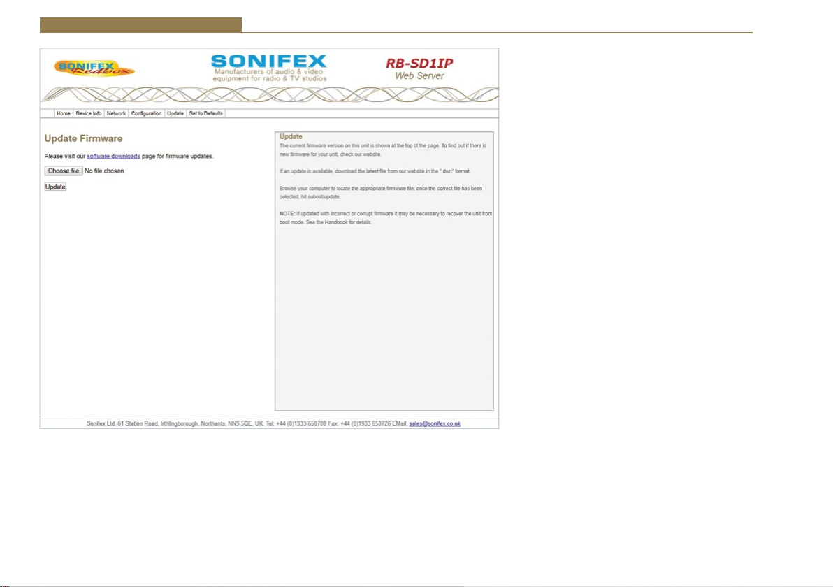
2 Silence Detectors - RB-SD1IP
Update
The current firmware version on this unit is
shown at the top of the page. To find out if there
is new firmware for your unit, check our website.
If an update is available, download the latest file
from our website in the “.dwn” format.
Browse your computer to locate the appropriate
firmware file, once the correct file has been
selected, hit submit/update.
Note: If updated with incorrect or corrupt
firmware it may be necessary to recover the unit
from boot mode. See the Handbook for details.
Fig 2-18: RB-SD1IP Screenshot of the Webserver Update Firmware Page
32

Silence Detectors - RB-SD1IP 2
Technical Specification RB-SD1IP
Audio Specification
Maximum Input Level: +28dBu
Input Impedance: >100kΩ balanced
Maximum Output Level: +28dBu
Output Impedance: As input, except when using unbalanced
Frequency Response: 20Hz - 20kHz ±0.1dB
Gain: +8dB (for unbal input B - optional)
Noise: <-93dB, unity gain, ref +8dBu output for unbal
Distortion: As input for balanced input, <0.02% @ 1kHz ref
Rear Panel Connections and Controls
Inputs (Main &
Auxiliary):
Output: 2 x XLR 3 pin male (balanced)
Remotes: 15 way D-Type plug
GPIO: 9 way D-Type socket
Alarm Threshold: -15dBu to -60dBu in 3dB steps via rotary switch
Silence Detect Duration: 2 - 30 seconds in 2 second intervals & 125
Detection Type: Mono or Stereo, via DIP switch Mono, Stereo,
Silence Switch Defeat: Disable/enable silence switching, via DIP
Remote Start: Latched or momentary, via DIP switch or GUI
Ethernet: 10/100Mbps on 1xRJ45 socket with status LEDs
auxiliary input where output impedance <50Ω
input
+8dBu output for unbalanced input
4 x XLR 3 pin female (balanced, auxiliary can be
unbalanced)
0dBu to -60dBu in 3dB steps via web GUI
second option via rotary switch 1 second – 24
hours using web GUI
or dual mono via web GUI
switch or GUI
Mains Input: Filtered IEC, continuously rated 85-264VAC
Fuse Rating: Anti-surge fuse 1A 20 x 5mm (250VAC)
Front Panel Controls and Indicators
Controls (With
Indicators):
Indicator: Program and Alarm indicators for left and right
Reset: Recessed push button
USB Port: 1 x USB A socket
USB
The RB-SD1IP can act as a host for low powered USB Mass Storage devices
in order to playback Audio files as an emergency backup system for when
both Main and Auxiliary sources fail.
File System(s): FAT & FAT32
Supported Audio: .wav extension (16 bit Stereo PCM @ 44.1kHz
Note: Additional Audio support may be added in future updates
Equipment Type
RB-SD1IP Redbox Silence Detection unit with Ethernet
Physical Specification
Dimensions (Raw): 48cm (W) x 10.8cm (D) x 4.2cm (H) (1U)
Dimensions (Boxed): 58.5cm (W) x 22.5cm (D) x 7cm (H)
Weight: Nett: 1.4kg Gross: 2.0kg
@47-63hz 10W max
Source Select, Mode Select and Restore
source for both Main and Auxiliary channels,
power indicator
or 48kHz)
8 kHz, 11.025 kHz, 12 kHz, 16 kHz, 22.050 kHz,
24 kHz, 32 kHz, 44.1 kHz, 48 kHz
& USB
19” (W) x 4.3” (D) x 1.7” (H) (1U)
23” (W) x 8.9” (D) x 2.8” (H)
Nett: 3.1lbs Gross: 4.4lbs
33

3 Silence Detectors - RB-DSD1
3 RB-DSD1 Digital Silence Detection Unit
Introduction
Fig 3-1: RB-DSD1 Front Panel
The RB-DSD1 digital silence detection unit works in a similar way to the
Sonifex RB-SD1 analogue silence detection unit, but has AES/EBU, S/PDIF
and TOSlink inputs and outputs instead of analogue inputs and output
respectively. Designed to switch from one input to another in the event
of loss of audio, the unit is ideal at transmitter sites, or after the master
output of a studio, to switch in another audio source, or simultaneous
broadcast, should a master source fail.
The unit can switch:
• On loss of level of the main input.
• On loss of level on one channel of the main input.
• On loss of synchronisation lock of the main input.
The RB-DSD1 has 2 x digital stereo audio inputs, each one selectable via
front panel MAIN and AUX push buttons, from either AES/EBU balanced
XLRs, S/PDIF unbalanced phonos or TOSlink unbalanced optical inputs.
Sample rate converters on each input mean that sources of different sample
rates can be used with the output sample rate being defined independently.
Each input is user-defined as either the main source or auxiliary source and
both sources are monitored for failure, each having a remote failure alarm.
The colour of the MAIN and AUX push-buttons indicate which input is the
current output channel (green) and which input is the waiting channel (red)
input, with a flashing LED indicating loss of synchronisation.
34
In the event of the main source dropping below a pre-set level for a predetermined amount of time, the unit will automatically switch through to
the auxiliary signal. The silence detect level is adjustable between -39dBfs
and -84dBfs in 3dBfs steps via front panel DIPSwitches. The silence interval
can be adjusted between 0 seconds and 252 seconds in 2 second steps via
another front panel DIPSwitch block. A small cover panel can be screwed in
place to obscure the DIPSwitches to prevent tampering of the settings.
There are 2 stereo outputs to allow for distribution of the selected input
to multiple outputs. Each output is available as simultaneous AES/EBU
balanced XLRs, S/PDIF unbalanced phonos or TOSlink unbalanced optical
outputs. The output sample rates are selectable via rear panel DIPSwitches
from one of 32kHz, 44.1kHz, 48kHz, 88.2kHz, 96kHz, 176.4kHz or 192kHz.
The unit has TTL wordclock BNC and AES/EBU XLR synchronising inputs as
standard and optionally, the RB-SYA and RB-SYD synchronisation boards can
be fitted to synchronise the unit to analogue or digital video signals. A front
panel DIPSwitch block is used to decide whether the unit is synchronised
to Input1, Input2, the AES/EBU sync input, the wordclock sync input
or an optional video sync board. A front panel SYNC button selects the
synchronisation mode of the unit and the button flashes whenever the unit
is not synchronised to an incoming sync signal. Selectable sync modes are
as follows:

Silence Detectors - RB-DSD1 3
Master Mode
In this mode the digital output sample rate is simply set by, and locked to,
the internal on-board clock generator. No sync signal is used or required.
Auto Sync Mode
In this mode the digital output sample rate follows the selected sync input.
When the sync signal is not present the output sample rate will be set by,
and locked to, the internal on-board clock generator at the selected output
frequency.
Auto Lock Mode
In this mode no output will be generated until lock is achieved with a sync
signal. The digital output sample rate now follows the sync input. If the sync
signal is removed then the output sample rate will be set by, and locked to,
the internal on-board clock generator at the closest frequency available to
the previous sync input.
Slave Mode
In this mode the digital output sample rate follows the sync input. When
the sync signal is not present the digital output is turned off.
The unit can operate in 2 modes - automatic or manual, selectable using
a rear panel DIPSwitch. In both modes it will automatically switch over to
the auxiliary source on detecting silence. When the main signal is again
detected it will either return to the main signal automatically or manually
depending on the mode chosen. In manual mode, the front panel RESTORE
button is used to return to the main signal.
The RB-DSD1 has a number of remote operational features. Remote outputs
provide separate relay contact closures for failure of the main and auxiliary
inputs. You can also remotely select between auto and manual mode (with
tally output), action the signal RESTORE, set the silence detection delay to
be 2mins 5 seconds and define which input is the main input (with tally
output). You can remotely start and stop another piece of equipment on
alarm failure and there is an option to set the remote start output as either
momentary or latched.
The unit can be configured to alarm when either the left or right channel of
the main input source fails, or if the whole stereo signal fails. Additionally,
if one channel of a stereo signal is lost, you can define whether to mute
the lost channel, or whether to mix the remaining channel to the lost side,
effectively creating a mono signal. If the main source synchronisation is
lost, you can define whether the unit switches to the auxiliary input in the
minimum time (2 seconds), or whether to treat the signal as silence to be
detected and then switched based on the unit’s silence detection settings.
Front panel LED indicators by the MAIN and AUX buttons show individually
left and right programme and alarm conditions for both the main and
auxiliary inputs.
A powerful feature of the RB-DSD1 is that by using the Sonifex SCi serial
software, the unit can be programmed for different delay durations, levels
and switching functions so that you can programme the unit for your
specific application. A front panel DIPSwitch configures the unit to be
controlled serially and a front panel LED indicates serial operation. Contact
Sonifex for further information if you have a particular requirement that
isn’t catered for by the RB-DSD1 as standard.
The RB-DSD1 has been designed to have a passive signal path through the
main input, so if power to the unit fails, signal input 1 is routed to output
1 and signal input 2 is routed to output 2. This is essential for applications
such as installation at transmitter sites, where a power failure to the
unit should not prevent the audio input signal from being output to the
transmitter. Note: This applies to the AES/EBU & S/PDIF I/O, but not the
TOSLink optical I/O.
35

3 Silence Detectors - RB-DSD1
Digital Input 1
S/PDIF
AES
Optical
Freq Select
AES Sync
Word Clock
Video Optional
Optical
AES
S/PDIF
Digital Input 2
Digital Source
Select
Master
Clock
Generation
AES RX
WC RX
VID RX
RX SRC
Clock
Select
RX SRC
Fig 3-2: RB-DSD1 System Block Diagram
Front Panel Controls and Indicators
The LED in the front panel is normally red to indicate power to the unit.
Duration
& Serial
Settings
Stereo/Mono
& Sync
Settings
Power
Failure
Relay
DSP
Power
Failure
Relay
Serial
LED
Digital Output 1
S/PDIF
TX
TX
AES
Optical
Optical
AES
S/PDIF
Digital Output 2
Reset
Button
Fig 3-3: RB-DSD1 Front Panel Controls and Indicators
36
Level
Settings
MAIN
Button &
Indicators
AUX
Button &
Indicators
RESTORE
Button &
Indicator
SYNC
Button &
Indicators

Silence Detectors - RB-DSD1 3
MAIN Source Select and Indicators
This button allows you to select which input source you would like to use,
from one of the AES/EBU, S/PDIF or TOSlink inputs. The three LEDs above
the button illustrate which source is selected. The button itself will also be
illuminated.
Button Colour Indication
Solid green Indicating that this is the input that
is currently being output
Solid red Indicating that this input is not
selected
Flashing between green and red Indicating a loss of lock to that
input
There are also green and red LEDs, one of each for both left and right
channels to show the programme and alarm state of the input. The
programme LEDs will be illuminated if the level is above the current silence
threshold. If the input is in an alarmed state, the red alarm LEDs will be
illuminated.
AUX Source Select and Indicators
The operation of this button is identical to the above.
RESTORE Button
The Restore button is used for restoring the main source signal when the
unit is operating in Manual Mode. When the main source signal returns
after it has timed out, the AUTO LED flashes, indicating that the source
signal can be restored. When the Restore button is pressed the main
source returns. This can be remotely controlled using pin 7 of the remotes
connector.
SYNC Mode button
This button allows you to cycle through the synchronisation modes. The
LEDS around the button display which mode has been selected. If the
selected synchronisation source
(see front panel DIPSwitch section for settings) is not locked, the button will
flash green and red.
SERIAL Mode indicator
If serial mode is selected (see front panel DIPSwitch section for settings)
this led will be illuminated.
Reset Button
In the unlikely event that the RB-DSD1 unit fails to respond, press the reset
button to reboot the unit (see Fig 10-3 for location).
Front Panel DIPSwitches
The front panel DIPSwitches are concealed behind the screw panel located
on the front of the unit.
Silence Detect Duration Control
Switch 1 2 3 4 5 6 7
Seconds 2 4 8 16 32 64 X2
The silence detect interval DIPSwitches adjust the duration over which a
silence is detected before alarming which ranges from 2-252 seconds (by
adding together the raised DIPSwitches, in 2 second intervals). If all the
DIPSwitches are down, (off) the duration defaults to 30 seconds. This can
be changed using the SCi serial software.
Serial Mode Setting
To activate serial mode, set DIPSwitch 8 on (up).
When activated, the serial mode LED illuminates
on the front panel (see Fig 10-3) and the unit can
be controlled serially instead of from the front
panel controls, using the SCi software.
Fig 3-4: SILENCE Detect Duration DIPSwitch
37

3 Silence Detectors - RB-DSD1
Silence Detect Audio Trigger Level
Switch 1 2 3 4
Seconds -3 -6 -12 -24
The trigger level DIPSwitches adjust the level
below which silence detection occurs. This level
may be varied from -39dBFS to -84dBFS in 3db
steps by summing DIPSwitches that are on and
adding -39dBFS. 0 (all off) represents -39 dBFS.
Stereo/Mono Selection
The configuration of this defines whether you want to switch sources when
the left and/or right channel of the incoming source go silent.
Switch Description
On When on, the unit operates in
stereo mode, whereby if one
channel goes quiet the unit
will switch, and requires both
channels to be present before it
switches back.
Off When off, the unit operates in
mono mode. In this mode the
unit will only switch when both
channels go quiet, and requires
only one channel to be present
before the unit switches back.
Fig 3-5: SILENCE Detect Audio Trigger Level DIPSwitch
Fig 3-6: SILENCE Detect Stereo/Mono & Sync Source DIPSwitch
Synchronisation Source Selection
Select which synchronisation source you would like to use by setting
DIPSwitches 2 - 4, marked SYNC MATRIX.
Synchronise from DIPSwitch 2 DIPSwitch 3 DIPSwitch 4
Main input Off Off Off
Aux input On Off Off
AES synchronisation
input
Wordclock input On On Off
Video sub board Off Off On
Off On Off
Rear Panel Controls
Fig 3-7: Rear Panel DIPSwitches
Output Sample Rate Selection
DIPSwitches 1 - 3 allow you to select what sample rate the output will be
when the unit is in master mode. Set the DIPSwitches where:
Sample Rate (kHz) DIPSwitch 1 DIPSwitch 2 DIPSwitch 3
32 Off Off Off
44.1 On Off Off
48 Off On Off
88.2 On On Off
96 Off Off On
176.4 On Off On
192 Off On On
38

Silence Detectors - RB-DSD1 3
Main/Aux Input Selection
DIPSwitch 4 defines whether the Main input is input 1 or 2.
DIPSwitch 4 Description
On When on, the Main input is input 2. The Aux input
is input 1.
Off When off, the Main input is input 1. The Aux input
is input 2.
Manual/Auto Mode Selection
DIPSwitch 5 defines whether the unit is in manual or automatic switch
mode.
DIPSwitch 5 Description
On When on, the unit is automatic mode. The restore
LED will be lit in this mode. The unit will switch
back to the main input automatically if the control
has been switched to aux and the main input level
has recovered for 2 seconds.
Off When off, the unit is in manual mode. The restore
LED will begin to flash if the control has been
switched to aux and the MAIN level has recovered.
The restore button will then switch the unit back to
the main input.
Remote Start Operation
DIPSwitch 6 defines whether the remote start switch is momentary or
latched. Used for starting external equipment when silence is detected.
DIPSwitch 6 Description
On When on, the remote start pin (pin 15) on the
remote connector is pulled low for half a second
when the unit switches to the auxiliary input.
(Momentary contact).
Off When off, the remote start pin on the remote
connector is pulled low when the unit switches over
to the auxiliary input and remains low until the unit
switches back to the main source or, if in manual
mode, is restored by the user locally or remotely.
(Latched contact).
Operation On Loss Of One Channel
DIPSwitch 7 defines how the unit reacts to the loss of one channel.
DIPSwitch 7 Description
On When on, the unit will output the remaining
channel to the lost channel to create a dual mono
output.
Off When off, the unit will simply mute the lost channel
and continue.
39

3 Silence Detectors - RB-DSD1
Operation On Loss Of Lock
DIPSwitch 8 defines whether the unit treats a loss of lock as a severe event
or as a simple loss of level.
DIPSwitch 8 Description
On When on, the unit will treat the loss of lock
condition as severe and the unit will switch to the
Aux input after 2 seconds.
Off When off, the unit will treat the loss of lock no
differently to a loss of level.
Remote Stop Operation
DIPSwitch 9 defines whether the remote stop is operational. Used for
stopping external equipment when the unit recovers from a switched state.
DIPSwitch 9 Description
On When on and Remote Start is set to momentary,
pin 4 will close to pin 11 on the remote connector
for half a second. Remote start operation is also
affected. If no level is detected on the channel
which has been switched to, the remote start pulse
will repeat every ten seconds. Please note that the
aux alarm will not work in this mode.
Off When off, the aux alarm operates normally.
Switching Operation
DIPSwitch 10 defines whether the unit switches when it loses lock or the
level drops, i.e. any failure condition. This is so that the unit can signal a
failure without actually switching.
DIPSwitch 10 Description
On When on, the unit will not switch on any fail
condition.
Off When off, the unit will switch on any fail condition.
Firmware Mode
DIPSwitch 12 defines the boot up mode.
DIPSwitch 12 Description
On When on, the unit boots in bootstrap mode.
Off When off, the unit boots in ‘normal’ configuration.
40
Silence Detectors - RB-DSD1 3
Remotes Connector
Displayed below are the pin connections and descriptions for the remote
connector:
Pin No. Signal I/O Description
Pin 1 Master Alarm Normally Open O Relay 1 N/O to Pin 9 in
alarm state
Pin 2 Master Alarm Normally Closed O Relay 1 N/C to Pin 9 in
alarm state
Pin 3 Aux. Alarm Normally Open O Relay 2 N/O to Pin 11 in
alarm state
Pin 4 Aux. Alarm Normally Closed O Relay 2 N/C to Pin 11 in
alarm state
Pin 5 Mode Switch I Momentary make to
Pin 8
Pin 6 Mode Indicator O Internal Open Collector
to Digital
Pin 7 Restore Switch I Momentary make to
Pin 8
Pin 8 Digital Ground - -
Pin 9 Master Alarm Common O N/O to Pin 1, N/C to Pin
2 in alarm state
Pin 10 Max Time Whilst Latched I Latched make to Pin 8
Pin 11 Aux. Alarm Common O N/O to Pin 3, N/C to Pin
4 in alarm state
Pin 12 +5V O To power up to a
maximum 100mA
Pin 13 Source Select Indicator O Internal Open Collector
to Digital Ground
Pin 14 Source Select Switch I Momentary make to
Pin 8
Pin 15 Remote Start O Internal Open Collector
to Digital Ground
Pins 1 - 4 are for external use to replicate the alarm conditions for the Main
and Auxiliary inputs.
Pins 5 - 7, 13 and 14 are to replicate the switches and indicators for the
source select, mode and restore functions.
Pins 8, 9, 11 and 12 are common or voltage pins.
Pin 10 is to select remotely the 2min 5secs silence time. This may be useful
for the broadcast of Remembrance Day services, or where you expect a
silence of up to 2 minutes to be broadcast. The maximum silence time is set
whilst the contact is latched.
Pin 15 is used to remotely start an external piece of equipment and
operates on audio fail.
RS232
The 9-way ‘D’ type socket connector carries a standard RS232 interface and
allows direct connection to a serial port on a PC via a pin-to-pin cable. The
pin assignments are as follows:
Pin 2: Transmit data
Pin 3: Receive data
Pin 5: Ground
All other pins are unused.
41

3 Silence Detectors - RB-DSD1
RB-DSD1 Inputs & Outputs
AES/EBU
Stereo
Digital Outputs
Fig 3-8: RB-DSD1 Rear Panel
AES/EBU Inputs
The digital input XLR 3 pin socket has an impedance of 110Ω. It has the
following connections:
Pin 1: Screen
Pin 2: Phase
Pin 3: Non-phase
The signals on this connector should meet the IEC 60968 specification
S/PDIF Inputs
The S/PDIF digital phono input have an impedance of 75Ω.
Optical Inputs
The digital audio optical input meets the TOSLink specification used by most
professional & consumer equipment.
S/PDIF
Outputs
Optical Outputs Optical Inputs Word Clock
AES/EBU
Stereo Digital
Inputs
S/PDIF
Inputs
AES/EBU
SYNC
Input
SYNC Input
AES/EBU Sync Input
The digital input XLR 3 pin socket has an impedance of 110Ω. It has the
following connections:
Pin 1: Screen
Pin 2: Phase
Pin 3: Non-phase
The signals on this connector should meet the IEC 60968 specification
Word Clock Input
The S/PDIF digital phono input has an impedance of 75Ω.
AES/EBU Outputs
The digital output XLR 3 pin socket has an impedance of 110Ω. It has the
following connections:
Pin 1: Screen.
Pin 2: Phase.
Pin 3: Non-phase.
The signals on this connector comply with the IEC 60968 specification
Optional
Video SYNC
Input
Settings Remote
RS232
Input
Connector
42

Silence Detectors - RB-DSD1 3
S/PDIF Outputs
The digital output S/PDIF phono output has an impedance of 75Ω.
Optical Outputs
The digital audio optical output meets the TOSLink specification used by
most professional & consumer equipment.
The outputs have an unweighted dynamic range of at least 138dB and
a THD+N noise of or better than –137dB. The data at the outputs are
presented as 24 bit wide.
Serial Port Control
The Serial Port allows the RB-DSD1 to be controlled and updated from a PC
via a pin-to-pin serial cable, using the Sonifex Serial Control Interface (SCI)
software. This software is available as a free download from the Sonifex
website at www.sonifex.co.uk/sci.
Default Settings for the Serial Port
Baud Rate: 19200
Data Bits: 8
Stop Bits: 1
Parity: Even
Handshaking: XON/XOFF
Fig 3-9: Serial Port Default Settings
Serial Interface Commands and Responses
Most of the commands follow the same structure: a 3 letter command
followed by a colon, followed by a parameter (if any) and terminated by
Carriage Return with optional Line Feed. A Line Feed character may be sent
but it will be ignored by the RB-DSD1. Commands are not case sensitive.
Responses are CR & LF terminated.
After the RB-DSD1 has been powered-up, an initialisation string is sent
“Initialising DSD1”.
Following are the commands and the expected responses:
Serial Protocol RB-DSD1
Command Description Response
AOM:nn -ACK:
nn represents which channel has been chosen
00 = Manual return
01 = Auto return
Bnn: Baudrate change where -ACK:
nn is the new baudrate value where:
11 – 115200
57 – 57600
38 – 38400
19 – 19200
96 – 9600
DEL:nnn Delay length in seconds where -ACK:
nnn is the number of seconds between 2 and 252
DFD:nnn Default delay length in seconds where -ACK:
nnn is the number of seconds between 2 and 252
43

3 Silence Detectors - RB-DSD1
Command Description Response
DWN: Initiates a firmware upgrade -ACK:
FPS: Front panel and unit status where response is:
-FPS:aa_bb_cc_dd_ee_ff_gg_hh_iii_jjj_kk_llllll_mmn_nnn
aa = Input1 source selection
bb = Input2 source selection
where 00 = AES, 01 = SPDIF, 02 = TOSLINK
cc = Sync mode selection
where 00 = Master, 01 = Auto, 02 = Auto lock, 03 =
Slave mode
dd = Serial flag indication
where 00: Serial mode off, 01 = Serial mode on
ee = Frequency
where 00 = 32k, 01 = 44.1k, 02 = 48k, 03 = 88.2k, 04 =
96k, 05 = 176.4k, 06 = 192k
ff = Mono/stereo
where 00 = mono, 01 = stereo
gg = Sync from
where 00 = Input 1, 01 = Input 2, 02 = AES sync, 03 =
Word clock, 04 = Video sync
hh = Rear DIPSwitch settings
where hh is a hex value built from the sum of all
applicable from:
01 = Remote stop selected
02 = No switching
08 = Input 2 as main source
10 = Auto mode selected
20 = Remote start is momentary
40 = Dual mono on lost channel in stereo mode
80 = Fail immediately on loss of lock
iii: Default delay
jjj: Delay time settings
where iii and jjj are a value in seconds between 2 and 252
kk: Remote settings
where 80 = Pin 10 is actioned on remote port
llllll: Level settings
where llllll is a 24 bit hex value defining the current
switch level.
mmm: Recovery time 1
where mmm is the current recovery time set for MAIN
between 2 and 252 in seconds
nnn: Recovery time 2
where nnn is the current recovery time set for AUX
between 2 and 252 in seconds
FRQ:nn Output framerate selection where -ACK:
nn selects which framerate is selected for the output
where:
00 = 32k
01 = 44.1k
02 = 48k
03 = 88.2k
04 = 96k
05 = 176.4k
06 = 192k
IOD:nn Fail immediately or delay on loss of lock where -ACK:
nn selects between the two modes
00 = Use standard delay on loss of lock
01 = Fail immediately
LEV:nn Level settings in dBFS -ACK:
nn sets the level of silence between -39 and -84
MIS:nn Switch which input is represented on the
MAIN side where -ACK:
nn represents which channel has been chosen
00 = Main is input 1
01 = Main is input 2
MOD:nn Sync mode selection where -ACK:
nn selects the synchronization mode where:
00 = Master mode
01 = Auto mode
02 = Auto lock mode
03 = Slave
MOS:nn Mono or stereo selection where -ACK:
nn selects between the two options where:
00 = Mono mode
01 = Stereo mode
44

Silence Detectors - RB-DSD1 3
Command Description Response
NOS:nn No switch on failure where -ACK:
nn selects between the two options where:
00 = Switch on failure
01 = No switch on failure
OCL:nn one channel (left or right) lost mode where -ACK:
nn selects between two options where:
00 = Mute the lost channel
01 = Send remaining channel to the other (dual mono)
REM:nm Remote Control options where -ACK:
n selects which option is being set where:
1 = Remote start mode
2 = Remote stop mode
3 = Remote Restore select
m selects the state of the option chosen where:
0 = Option deselected or off
1 = Option selected
RTx:nnn -ACK:
x sets the channel which is being changed where:
1 = MAIN
2 = AUX
nnn sets the amount of seconds it takes for the
channel to recover in seconds
SPM:nm Special mode selection where -ACK:
n selects which modes is being selected where:
1 = signal detection mode
2 = Force main mode
3 = Emergency program override
4 = Detection enabled/disabled mode
m selects the state of the option chosen where:
0 = Mode turned off
1 = Mode selected
SRQ: Status Request where -SRQ:aa_bb_cc_dd_ee_fg_hhhh_ii
aa = Input1 lock status
bb = Input2 lock status
where 00 = unlocked and 01 = locked
cc = Restore flash
dd = Sync flash
where 00 = Not flashing and 01 = flashing
ee = Output switched
where 00 = Switched and 01 = Not switched
fg:
f = alarm status and g = program level status
where f and g are hex values built from the sum of:
1 = Input 1 L
2 = Input 1 R
4 = Input 2 L
8 = Input 2 R
For example if input 1 was in a good state but input 2 was alarmed the
value would be C3
Alarm status = Input 2L + Input 2R = 4+8 = C
Program level status = Input 1L + Input 1R = 1+2=3
hhhh: Remote port status
where hhhh represents hex values built from the sum of:
01: Main alarm
02: Aux alarm\remote stop indicator
04: Auto indicator
08: Remote start indicator
10: Source indicator
Follow above example for further clarification
ii: Current special mode
where ii is a hex value based on which mode is selected:
00: No special mode
01: Signal detection mode
02: Force main mode
04: Emergency overide mode
08: Detection enabled/disabled mode
45

3 Silence Detectors - RB-DSD1
Command Description Response
SSx:nn Source select where -ACK:
x selects which input is being changed where:
1 = MAIN
2 = AUX
nn selects which source is used for that particular
input where:
00 = AES
01 = SPDIF
02 = Optical
SYS:nn Sync source select where -ACK:
nn selects which sync source is used where:
00 = Input 1
01 = Input 2
02 = AES
03 = Wordlock
04 = Video
UID: Unit id where -UID:RB-DSD1
VER: Version number where
-VER:x.xxx,y.yyy
Where x.xxx is the firmware version and y.yyy id the front
panel firmware version number
Error Messages
The following error messages can be returned for illegal commands
Err:01 = Return if command not found
Err:02 = Return if missing parameter
Err:04 = Return if parameter out of range
46

Silence Detectors - RB-DSD1 3
SCi for RB-DSD1
The free of charge Sonifex SCi software allows the user to control the RBDSD1 remotely. The interface has three tabs including a unit setup page,
an indication page and a miscellaneous options page. The status of the
connection, serial number and firmware versions are always visible at the
bottom of the screen.
Please note: In order to edit the options on the Unit Setup and
Miscellaneous pages, the RB-DSD1 must have the front panel SERIAL mode
DIPSwitch set to on (DIPSwitch 8, see page 40).
Indication Page
Fig 3-10: Indication Page
This page displays the current status of the unit. Each
channel (Main and Aux) has an indicator panel which
displays:
Program Level: The current audio status is displayed as it is
on the front panel.
Locked LED: If the input is locked, this LED will be lit.
Alarm LED: If the input is alarmed, this LED will be lit.
Output LED: If the input is being used as the current output,
this LED will be lit.
Input Segment Display: The number in this box indicates
which input is currently being used for this channel’s input.
Source Label: The source which is currently being used is
displayed here.
Remote Start & Stop: The remote start and remote stop
signals are displayed in the remote indicator panel. When
either of these signals is active, the relevant led will be lit.
Synchronization options are displayed in the sync indicator
panel:
Mode: This displays the selected sync mode.
Source: This displays the selected sync source. This is
disabled in Master mode.
Sample Rate: This displays the current output sample rate.
Sync Source Locked LED: If the synchronization source is
locked this LED will be lit.
Restore: The Restore button can be used to complete the
restore function if the unit is in manual mode. The LED (to
47

3 Silence Detectors - RB-DSD1
the left of the button) will flash if the unit is ready to be restored. If the LED
is lit continuously, the unit is in auto mode.
Serial Mode: The serial mode LED indicates whether the unit is in serial
mode.
Unit Setup Page
Fig 3-11: Unit Setup Page
The control page is where you can configure your unit. For ease of use, the
options have been split into four sections:
1. Select Input Sources
Select which source you would like to use for both the Main
Input and the Aux Input from the drop down boxes labeled
“Main is” and “Aux is” respectively.
2. Select Synchronization Options
Select which sync mode to use from the first drop down
box, labeled “Sync Mode Is”. If “MASTER” is chosen, then
simply select your output sample rate from the drop down
box labeled “where sample rate is”. If “AUTO”, “AUTOLOCK”
or “SLAVE” are selected, then a new drop down box labeled
“From” will appear which allows the user to select the
synchronization source.
3. Select Trigger And Switch Time Options
Select the trigger level in the first box by typing a value in
the box labeled “Trigger level is minus” and pressing return
to confirm. The highest value you can enter is 39 and the
lowest is 84. Please remember that the value entered is
actually a negative value.
The switch time (the time it takes for a low level channel
to be registered as a failure and consequently switched to
Aux) is determined by the value in the box labeled “Switch
time is”. Again, type a value in the box and press return to
confirm it. “2” is the minimum value accepted, “252” is the
maximum.
Please note that if the unit is not in Serial Mode and all
front panel time switches are off, you can set the default
delay by typing in the desired value between 2 - 252 in the
‘Switch Time is’ box and press return.
The Recovery time (the time needed for a level to be
confirmed as good after an alarm state) can be set in the
48

Silence Detectors - RB-DSD1 3
box labeled “Recovery time is” for the main input and the
box labeled “and” for Aux.
There are two tick options that can be selected. Click on the
check box to select the option:
• Turn off switching
• Fail (2 seconds) on loss of lock
4. Select Operational Modes
Select which input is the main input by using the drop down
box labeled “Main is”.
Select how the unit will return from failure by using the
drop down box labeled “The Unit Will Return”.
There are four tick options that can be selected. Click on the
check box to select the option:
• Stereo switching required
• Dual mono on loss of one channel - Dual mono the
output when the left or right channel is lost in stereo
switch mode
• Remote start is momentary, rather than latched
• Remote stop required - If remote start is momentary,
then remote stop can be selected.
Miscellaneous Page
Fig 3-12: Miscellaneous Page
This page is used for the connecting and disconnecting SCi to the unit and
for updating the firmware. The Special Modes are also selected form here.
Updating The Firmware
The RB-DSD1 firmware will at times be updated to add new features, or to
correct any possible issues that may arise. Check for updates at:
http://www.sonifex.co.uk/technical/software/
49

3 Silence Detectors - RB-DSD1
To update the firmware click on the button labeled “Update Firmware”
and then select the downloaded firmware file. Firmware files for the RBDSD1 always have an “.dwn” extension. A progress bar will appear in SCi,
indicating how much of the file has been uploaded to the unit.
When the unit switches to update mode, the front panel display leds will all
be extinguished. The left program LED is then used to display the status of
the upload:
Uploading the Code: The LED will begin to flash amber to confirm the unit
is receiving the new firmware to RAM.
Copying Code To Flash Memory: The LED will be solid amber while the
unit checks the integrity of the file and copies the file from RAM to flash
memory.
Successful Update: The LED will turn green for two seconds and the unit
will automatically reset and begin running the new code.
Unsuccessful Update: The led will turn red for two seconds and the unit will
return to running the last code used.
Special Modes
Signal Detection Mode
In this mode the three remote buttons are disabled (mode, source and
restore). The recovery time is automatically set to zero for both channels.
All other functions operate as in normal mode.
Force Main Mode
In this mode only the remote mode control input has any effect. When this
control input is active (low) the output is forced to Input 2 (MAIN input)
regardless of whether audio is present. The unit operates in auto mode and
with input 2 as the MAIN input. All other functions operate as in normal
mode.
Emergency Program Override Mode
In this mode all alarm LEDS are illuminated whenever the main input is
active. This is to indicate that the emergency paging program is active on
the MAIN input. When the paging program goes silent, the unit will revert
back to the AUX input and all the alarm LEDS will switch off. All other
functions operate as in normal mode.
Detection Disable/Enable Mode
In this mode the silence detection can be disabled and enabled remotely.
The SCi “Detection is” drop down box and the remote source button is
used to switch between the two modes. The “Detection is” drop down
box toggles the state, while the remote source control (pin 14 on the
remote connector) can only ENABLE the silence detection feature. Pin 10
on the remote connector is used to DISABLE silence detection. When the
unit powers up Silence Detection is always enabled. The remote source
select indicator (Pin 13 on the remote connector) is enabled when Silence
Detection is disabled. In this mode Input 1 is always the MAIN input and
Input 2 is always the AUX input. The AUX alarms are masked for both front
panel indicators and remote alarm relay, for as long as the MAIN input is
present.
When Special Modes are selected, certain controls are disabled or altered:
Signal Detection Mode: Main Input and return mode selection is disabled.
Recovery times are set to zero.
Force Main Mode: Main Input and return mode selection is disabled.
Emergency Program Overide Mode: Main Input selection is disabled.
Detection Enabled/Disabled Mode: The Main Input selection label
becomes “Detection Is” and the options available change to “ENABLED” and
“DISABLED”.
50

Technical Specification For RB-DSD1
Silence Detectors - RB-DSD1 3
Audio Specification
Dynamic Range: >138dB
Distortion and Noise: <-137dB THD + N at 1kHz, ref 0dB FS
Input & Output Impedances:
110Ω ±20% AES/EBU balanced I/O
75Ω ±5% S/PDIF unbalanced I/O
75Ω ±5% TOSlink unbalanced I/O
50Ω BNC TTL word clock input
Signal Level: Balanced: 3V/10V peak to peak min/max
Unbalanced: Min 0.5V±20% peak to peak
Sample Frequencies: 32, 44.1, 48, 88.2, 96,176.4 or 192kHz
Bit Depth: Up to and including 24 bit
Front Panel Operational Controls & Indicators
Digital Input Select: AES/EBU, S/PDIF or TOSlink optical via INPUT 1
or INPUT 2 push-buttons
Sync Input Select: AES/EBU, wordclock, INPUT 1, INPUT 2 or video
board, via front panel DIPSwitch
Sync Mode Select: Master, slave, auto or auto lock, via SYNC
push-button
Alarm Threshold: -39dBfs to -84dBfs in 3dBfs steps via front
panel DIPSwitches
Silence Detect Duration: 0 - 252 seconds in 2 second intervals via front
panel DIPSwitches
Detection Type: Mono or stereo, via front panel DIPSwitch
Restore Control: Manual restore button & mode indication LED
Indicators: Program and alarm indicators for left and right
sources for both main and auxiliary inputs
Rear Panel Operational Controls
Master Frequency Select: 32, 44.1, 48, 88.2, 96,176.4 or 192kHz via rear
panel DIPSwitches
Input Select: Main input from INPUT 1 or INPUT 2 via
DIPSwitch
Restore Mode: Automatic or manual, via DIPSwitch
Remote Start: Latched or momentary, via DIPSwitch
Channel Loss: Mute channel or mix remaining, via DIPSwitch
Sync Loss: Switch immediately or treat as silence delay,
via DIPSwitch
Connections
Digital Inputs: 2 x AES/EBU XLR 3 pin female
2 x S/PDIF RCA phono
2 x TOSLink optical input
Digital Outputs: 2 x AES/EBU XLR 3 pin plug
2 x S/PDIF RCA phono socket
2 x TOSLink optical output
Sync Inputs: 1 x AES/EBU XLR 3 pin female
1 x Word Clock BNC
1 x Video Input (optional)
Remote I/O Port: 15 way D-type plug
Serial Port: RS232, RJ45 socket
Mains Input: Universal filtered IEC, continuously rated
85-264VAC @47- 63Hz, max 10W
Fuse Rating: Anti-surge fuse 1A 20 x 5mm
Equipment Type
RB-DSD1: Digital silence detection unit
51

3 Silence Detectors - RB-DSD1
Physical Specifications
Dimensions 48cm (W) x 10.8cm (D*) x 4.2cm (H) (1U)
(Raw): 19” (W) x 4.3” (D*) x 1.7” (H) (1U)
Dimensions 59cm (W) x 27.5cm (D) x 11cm (H)
(Boxed): 23.2” (W) x 10.8” (D) x 4.3” (H)
Weight: Nett: 1.4kg Gross: 2.0kg
Nett: 3.1lb Gross: 4.4lb
Accessories
RB-SYA: Analogue video sync board (NTSC, PAL
& SECAM)
RB-SYD: Digital video sync board (SD-SDI & HD-SDI)
RB-RK3: 1U Rear panel rack kit for large Redboxes
* Note that this product is deeper than standard Redboxes
52

Silence Detectors - RB-DSD1 3
4 RB-DSD8 8 Channel Silence Switcher
Status Buttons Channel Controls & Indicators
Reset Button
Fig 4-1: RB-DSD8 Front Panel
The RB-DSD8 8 provides silence detection over 8 channels of audio,
organised as 4 pairs. The pairs can be either analogue or digital and can be
used independently to act as 4 independent silence detectors or they can
be linked to switch simultaneously. The unit is designed to switch from the
main input to the backup input in the event of loss of audio.
The unit can switch:
• Automatically when the main input level is below the set switching level
• Automatically when the digital input becomes unlocked.
• Manually by front panel or remote control button press.
• Manually by webserver or serial interface.
The audio inputs can be analogue or digital, with ADCs incorporated into
the input paths. The input path switches based on digital lock, allowing
for automatic input selection. The output is also selectable as analogue or
digital. This is achieved by a DAC in the output path and can be switched
in manually by rear panel DIPswitches. The unit switch level settings are in
dBFS. When using analogue signals, the equivalent full scale value can be
set to +24dBU, +18dBU, or +12dBU by rear panel DIPSwitches. Since the
silence detection feature can be switched off, this means the unit can also
be used as an 8 channel AD/DA.
Each pair has individual settings and controls but share settings once they
are linked. The foremost pair determines the switching characteristics and
controls to be used. Each stereo pair has an AES LED that shows the status
of the digital audio on that channel and a selection LED to show which input
is currently being sent to each output. Two presence LEDs, one for each
mono input of each pair, indicate the current input level.
The unit can switch between sources automatically or manually at the push
of a button. If switching manually, silence detection is disabled and the
user chooses when to switch using the main or backup buttons. If switching
automatically, the unit will switch between the two sources automatically
upon the detection of silence. Each pair can be set to switch manually or
automatically and the current setting is indicated by the mode LED. The unit
can also return back to the main input manually or automatically, and the
automatic return can be delayed.
Link/Select buttons are used to group channels to access multichannel
operation. Each pair has a Link/Select button which illuminates blue when
active. Pressing and holding the first Link/Select button with any other Link/
Select button causes all inputs up to that point to be selected.
The RB-DSD8 has a slave mode facility that allows you to connect two
RB-DSD8 units and control them simultaneously from one unit.
Rear Panel
DIPSwitch
Indicators
53

4 Silence Detectors - RB-DSD8
The silence detect level is adjustable between -27dBFS and -84dBFS in
3dBFS steps via DIPSwitches and this level is compared to peak signals. The
silence interval can be adjusted between 2 seconds and 252 seconds in
2 second steps via DIPSwitches. The return duration can also be adjusted
between 2 seconds and 252 seconds.
A powerful feature of the RB-DSD8 is that by using the in-built web server
or Sonifex SCi serial software, the unit can be programmed for different
delay durations, levels and switching functions so that the unit can be set
up the unit for any specific application. Set a DIPSwitch to configure the unit
to be controlled serially or via web server, this is indicated by a front panel
LED. Now you can connect to the unit using either USB or Ethernet. Contact
Sonifex for further information if you have a particular requirement that
isn’t catered for by the RB-DSD8 as standard.
The RB-DSD8 has been designed with dual redundant power supplies. This
means that if either power supply fails, the other is ready to take over. In
the extremely unlikely event that both fail, the unit has been designed
with a passive signal path through the main input. This is essential for
applications such as installation at transmitter sites, where a power failure
to the unit should not prevent the audio input signal from being output to
the transmitter.
Clocking & Synchronisation
All digital input signals are routed to a sample rate converter allowing mixed
incoming sample rates to be used. The output sample rates are selectable
via DIPSwitches from a predefined master clock of 32kHz, 44.1kHz, 48kHz,
88.2kHz, 96kHz, 176.4kHz or 192kHz or the clock can be derived from a
synchronisation input. When analogue inputs are selected, the analogue to
digital converters are also clocked at that sample rate.
DIPSwitches can be used to choose the synchronisation mode and the
synchronisation source from TTL wordclock or AES/EBU through the dualpurpose synchronising input as standard. A front panel indicator shows the
status of the synchronization input. Selectable synchronisation modes are
as follows:
Master Mode
In this mode the digital output sample rate is simply set by, and locked to,
the internal on-board clock generator. No synchronisation signal is used or
required.
Auto Lock Mode
In this mode the digital output sample rate will follow the synchronisation
input. If the synchronisation signal is removed then the output sample rate
will be set by, and locked to, the internal on-board clock generator at the
closest frequency available to the previous synchronisation input.
Slave Mode
In this mode the digital output sample rate follows the synchronisation
input. When the synchronisation signal is not present the digital output is
turned off.
54

Silence Detectors - RB-DSD8 4
Front Panel Controls & Indicators
Fig 4-2: RB-DSD8 Status Buttons
Status Buttons
AUTO Button
This button is used to select automatic mode for all channels that are
selected using the Link/Select buttons. This button deactivates MANUAL
and SLAVE mode and illuminates green when selected. Press and hold
the button for two seconds to activate this mode. This mode can only be
selected from one of the other modes if the main signal is present and
above the threshold level. The button and the associated mode LED will
flash to indicate these conditions have been met. To restore to main from
backup in automatic mode push and hold the button for two seconds.
This selection is the default for all channels. When in AUTO mode, the
switch back can also be automatically controlled. This is set using the ASB
Command in the serial protocol or ‘Automatic Switch Back’ option on the
webserver’s general settings page.
MANUAL Button
This button is used to select manual mode for all channels that are currently
selected. This button illuminates red when selected and deactivates the
AUTO and SLAVE mode. Press and hold the button for two seconds to select
this mode. The MAIN and BACKUP buttons can then be used to control
which channel is selected.
SLAVE Button
This button is used to select the unit as slave controlled and is illuminated
yellow. Pressing this button disables both the MANUAL button and the
AUTO button. Press and hold this button for two seconds to select this
mode. Please note that SLAVE selection is applied across the whole unit.
All channels will revert to which ever mode is used to deactivate the SLAVE
mode.
MAIN Button
This button selects the main input as the output for the currently selected
channels. The button illuminates green if MAIN input is selected. This
selection is the default for all channels. Press and hold the button for 2
seconds to select the MAIN source. Please note that pressing and holding
this button at any time will select MANUAL mode.
BACKUP Button
This button selects the backup input as the output for the currently selected
channels. Press and hold the button for 2 seconds to select the BACKUP
source. The button illuminates red if BACKUP input is selected. Please note
that pressing and holding this button at any time will select MANUAL mode.
DISPLAY LEDS
Fig 4-3: RB-DSD8 Controls & Indicators For Each Channel
Presence LEDs 1(L) 2(R)
Each stereo input channel has an associated Presence LED which indicates
55

4 Silence Detectors - RB-DSD8
the level of that channel. Each LED has three states:
Green – This indicates that the level on that channel is above
threshold
Yellow – This indicates that the level on that channel is below
threshold
Red – This indicates that the channel is silent i.e. no audio at all
AES LEDs
Each channel pair has an AES LED associated. This LED indicates the status
of the digital audio. Each LED has four states:
Green – AES detected and everything is fine. The input sample rate
matches the output sample rate.
Yellow – AES detected and everything is fine. The input sample rate is
different to the output sample rate.
Red – AES detected but an error has been detected.
Off – No digital signal is present or the analogue input is being
used.
The following errors can create a red state:
CRC error
Parity error
Validity bit error
Biphase encoding error.
SEL LEDs
Each channel pair has a SELection LED associated with each stereo MAIN
and BACKUP input. This LED indicates which input is currently being
used for the output. The MAIN selection LED illuminates green when the
associated output is from the MAIN input. The BACKUP selection LED
illuminates red when the associated output is from the BACKUP input. Only
one of these two LEDs can be on for any one channel at any given time.
MODE LEDs
Each stereo pair of MAIN and BACKUP inputs has a MODE LED which
indicates which switching mode is currently being employed on that
channel. The MODE LED has three states:
Green – The channel is in AUTO mode
Yellow – The channel is in SLAVE mode
Red – The channel is in MANUAL mode
LINK/SELECT Buttons & LINK LED
There are four LINK/SELECT buttons, one for each channel pair. To link any
inputs simply press and hold the link buttons for 2 channels. All channels
between the selected channels will be included in the link. Once linked, the
yellow link LED between them will illuminate. For example, to link channels
1 & 2 ,3 & 4 and 5 & 6, press and hold the link buttons on channels 1 & 2
and 5 & 6 for 2 seconds. Whilst channels 1 & 2 and 3 & 4 are linked, there is
an additional option to link 5 & 6 and 7 & 8 together individually. To do this
press and hold LINK/SELECT 5 & 6 and 7 & 8 for 2 seconds. To release this
mode, press and hold either LINK/SELECT 5 & 6 or LINK/SELECT 1 & 2. The
left-most channel pair (usually channels 1 & 2) will dominate and all other
pairs will inherit their settings, with the new settings being reflected by
changes to the status indicators.
56

Silence Detectors - RB-DSD8 4
Additional Indicators
Fig 4-4: RB-DSD8 Additional Indicators
EXT SYNC LED
This LED displays the synchronisation mode that is currently selected. This
LED has five states:
Green – Master mode is selected
Yellow – Slave mode is selected
Flashing yellow – Slave mode selected but synchronisation is lost
Red – Auto mode is selected
Flashing red – Auto mode selected but synchronisation is lost.
Remote Control Indicator
If remote control mode is selected (see DIPSwitch section for settings) this
LED will be illuminated.
PSU (Power Supply) Indicators
Each PSU on the unit has its own indication LED. If both PSUs are working
and correct both LEDs are illuminated green. If the internal ADC circuitry
detects the level drop below a sufficient level on a particular supply, its
representitive LED will illuminate red instead to indicate a fault.
Reset Button
In the unlikely event that the RB-DSD8 unit fails to respond, press the reset
button to reboot the unit (see Fig 1-1 for location).
Reset to Default Settings Using the Reset Button
Press reset and wait for all of the front panel LEDs to illuminate. When they
turn off, a 5 second counter begins. Reset the unit within these five seconds
to increment the reset tally. Repeat process again to reset to defaults. If
the counter ever elapses, the reset tally will return to zero and the whole
process will need to start again.
57

4 Silence Detectors - RB-DSD8
Rear Panel DIPSwitch Settings
Fig 4-5: RB-DSD8 Rear Panel DIPSwitches
Rear Panel DIPSwitches: Bank 1 SILENCE LEVEL AND DURATION
Silence Detect Interval Control (DIPSwitches 1-7, Bank 1)
DIPSwitch 1 2 3 4 5 6 7
Seconds 2 4 8 16 32 64 128
The silence detect interval DIPSwitches adjust the duration over which
a silence is detected before alarming and ranges from 2-254 seconds by
combining raised (ON) DIPSwitches in 2 second intervals with 0 being
all DIPSwitches down. The default value is set at 30 seconds but can be
changed using the serial port or ethernet. This time can also be overridden
by a remote GPI/O input that sets the unit to an override time that is set to
2mins 5 seconds.
Silence Detect Trigger Level (DIPSwitches 8-11, Bank 1)
DIPSwitch 8 9 10 11
Level dBFS -3 -6 -12 -24
by raising different combinations (to ON). Please note the range changes
depending on the full scale settings. These represent -15dBU to -60 dBU
Full Scale Min Max
12dBU -27dBFS -72dBFS
18dBU -33dBFS -78dBFS
24dBU -39dBFS -84dBFS
Stereo/Mono Switch (DIPSwitch 12, Bank 1)
The configuration of this defines whether you want to switch sources
when left and/or right channel of the incoming source go silent. When
channels are linked the stereo mode becomes multichannel mode and any
single mono channel failure will cause the unit to switch sources; likewise
mono mode will require both channels to fail individually before switching
sources.
DIPSwitch 12 Description
When on, the unit operates in mono mode. In this
On
Off
Rear Panel DIPSwitches: Bank 2 DIGITAL AUDIO SETTINGS
Master Mode Frequency Selection (DIPSwitches 1-3, Bank 2)
These DIPSwitches allow you select what sample rate the output will be
when the unit is in master mode.
mode the unit will only switch when both channels
go quiet, and requires only one channel to be present
before the unit switches back.
When off, the unit operates in stereo mode, whereby
if one channel goes quiet the unit will switch, and
requires both channels to be present before it switches
back.
The trigger level DIPSwitches adjust the level below which silence detection
occurs. This level may be varied from -27dBFS to -84dBFS in 3db steps
58

Silence Detectors - RB-DSD8 4
Sample Rate
(kHz)
32 Off Off Off
44.1 On Off Off
48 Off On Off
88.2 On On Off
96 Off Off On
176.4 On Off On
192 Off On On
External Synchronisation Source (DIPSwitch 4, Bank 2)
Select which synchronisation source you would like to use by setting this
DIPSwitch:
DIPSwitch 4 Synchronise From
On Wordclock/AESEBU synchronisation input
Off Main Input Pair 1
Note: This DIPSwitch is redundant when running in synchronisation master
mode.
Synchronisation Mode Selection (DIPSwitches 5-6, Bank 2)
These DIPSwitches allow you select which synchronisation mode the unit
is in.
DIPSwitch 5 DIPSwitch 6 Synchronisation Mode
Off Off Master Mode
On Off Auto Mode
Off On Slave Mode
On On Reserved
DIPSwitch 1 DIPSwitch 2 DIPSwitch 3
Remote Start Mode Switch (DIPSwitch 7, Bank 2)
This defines whether the remote start switch is momentary or latched.
Used for starting external equipment when silence is detected on channel
1. The channel can be reassigned through the serial port.
DIPSwitch Description
When off, the remote start pin on the remote connector
On
Off
Loss of Lock Failure (DIPSwitch 8, Bank 2)
This defines whether the unit treats a loss of synchronisation lock as an
immediate switch event or as a simple loss of level.
Note: Switch this to ‘Off’ when using an analogue input.
DIPSwitch 8 Description
On
Off
is pulled low when the unit switches over to the backup
input and remains low until the unit switches back to the
main source or, if in manual mode, is restored by the user
locally or remotely. (Latched contact).
When on, the remote start pin (pin 7) on the remote
connector is pulled low for half a second when the unit
switches to the Backup input. (Momentary contact). If the
level detected on the backup channel is below the switch
threshold, the remote start will continue to pulse every
10 seconds until a valid signal is detected.
When on, the unit treats the loss of lock condition
as an immediate switch event. The unit switches
immediately to the Backup input.
When off, the unit treats the loss of lock no differently
to a loss of level.
59

4 Silence Detectors - RB-DSD8
Output Pair Configuration (DIPSwitches 9-12, Bank 2)
These DIPSwitches allow you select whether each output pair is analogue or
digital. Set each DIPSwitch so that:
DIPSwitch 9 - 12 Description
On When on, the pair outputs a balanced analogue signal.
Off When off, the pair outputs an AES/EBU digital signal.
DIPSwitch 9 = Channel Pair 1 & 2
DIPSwitch 10 = Channel Pair 3 & 4
DIPSwitch 11 = Channel Pair 5 & 6
DIPSwitch 12 = Channel Pair 7 & 8
Rear Panel DIPSwitches: Bank 3 MISC SETTINGS
Ignore Silence Settings (DIPSwitches 1-8, Bank 3)
Each channel has a DIPSwitch to determine whether it Is ignored when
AUTO silence switching.
DIPSwitch 1 - 8 Description
On When on, the channel is ignored.
Off When off, the channel is silence detected.
DIPSwitch 1 = Channel 1
DIPSwitch 2 = Channel 2
DIPSwitch 3 = Channel 3
DIPSwitch 4 = Channel 4
DIPSwitch 5 = Channel 5
DIPSwitch 6 = Channel 6
DIPSwitch 7 = Channel 7
DIPSwitch 8 = Channel 8
Remote Control Enable (DIPSwitch 9, Bank 3)
This DIPSwitch enables serial/ethernet settings which are determined by
the Sonifex SCi software.
DIPSwitch 9 Description
On When on, the unit uses the serial/ethernet settings.
Off When off, the unit uses on board/front panel settings.
Full Scale Line Up (DIPSwitches 10-11, Bank 3)
These DIPSwitches allow you set up the full scale line up of the ADCs and
DACs.
Note: These settings affect the silence level setting.
The settings are as follows:
DIPSwitch 10 DIPSwitch 11 Synchronisation Mode
Off Off 0 dBFS = 24 dBu
On Off 0 dBFS = 18 dBu
Off On 0 dBFS = 12 dBu
On On Reserved
Boot Mode (DIPSwitch 12, Bank 3)
This DIPSwitch forces the unit into boot mode. The firmware can be
updated from here in the unlikely event that the firmware becomes
corrupted.
Note: Firmware uploads can only be done via the serial port in boot mode.
Switch Description
On
Off When off, the unit powers up and boots normally.
When on, the unit powers up and boots into boot
mode.
60
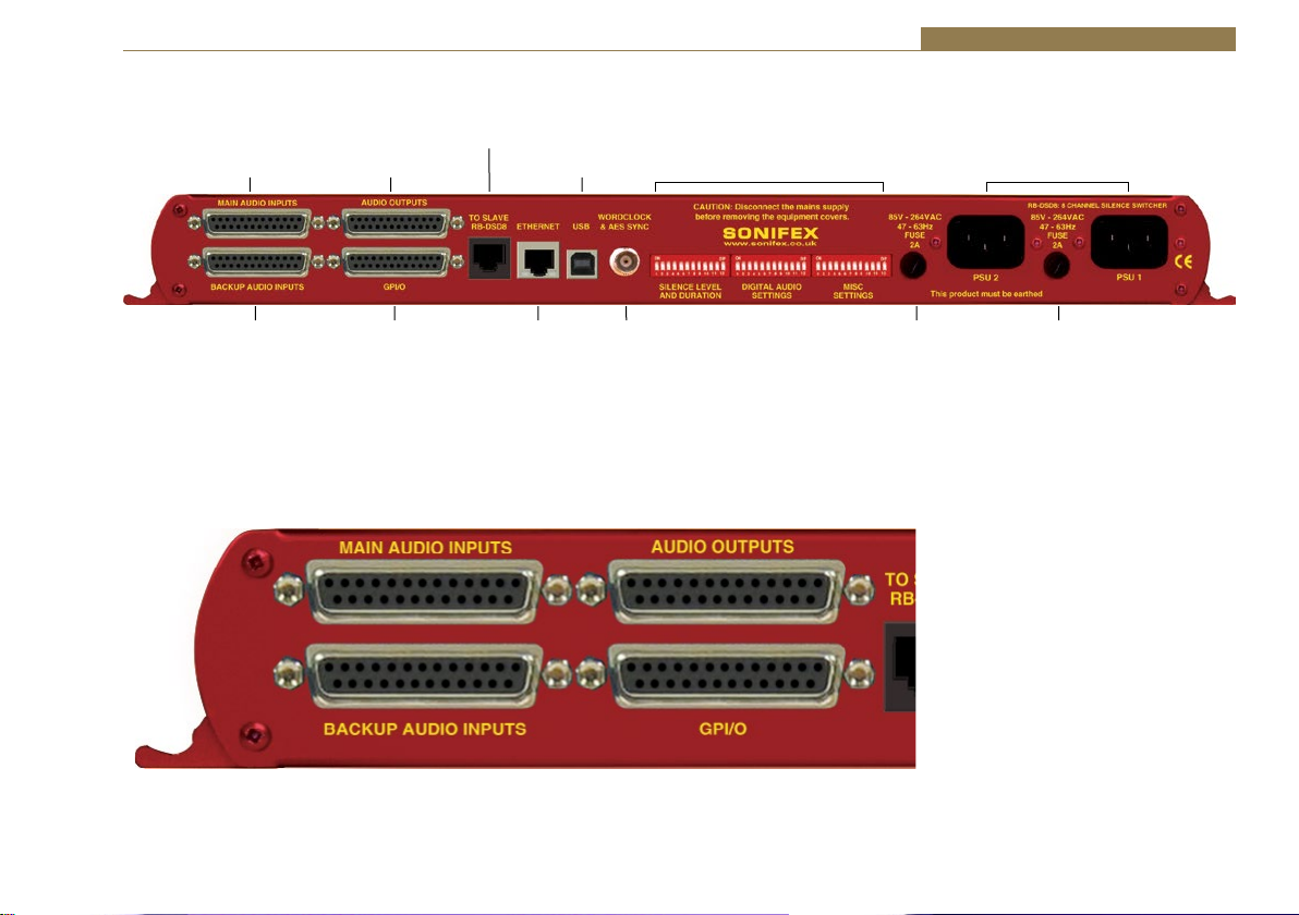
RB-DSD8 Rear Panel Connections
To Slave
Main Audio
Inputs
Audio
Outputs
RB-DSD8
USB
Connection
Silence Detectors - RB-DSD8 4
Power SupplyDIPSwitches
Backup Audio
Inputs
Fig 4-6: RB-DSD8 Rear Panel
Connection
WordclockEthernet
Audio Connections
There are 4 x 25-pin female D-type connectors which provide the audio
inputs/outputs and the general purpose inputs/outputs (GPI/O).
Fig 4-7: Audio & GPI/O Connector Detail
Fuse FuseGPIO
61

4 Silence Detectors - RB-DSD8
The leftmost two D-types provide for the simultaneous connection of up
to four stereo, (eight mono) analogue or digital audio inputs for both
Main and Backup sources. The rightmost two D-types provide eight stereo
analogue or digital outputs and the Remote GPI/Os, 9 inputs and 14
outputs. The pin assignations are as follows:
Pin 13 Pin 1
Pin 25 Pin 14
Fig 4-8: Audio Connector Pin Numbers
Connector
Pin Number
Audio Inputs Audio Outputs
Analogue Input 1 L+ or
1
Digital Input 1+
Analogue Input 1 L- or
14
Digital Input 1Analogue Input 1 Ground or
2
Digital Input 1 Ground
Analogue Output 1 L+ or
Digital Output 1+
Analogue Output 1 L- or
Digital Output 1-
Analogue Output 1 Ground
or Digital Output 1 Ground
15 Analogue Input 1 R+ Analogue Output 1 R+
3 Analogue Input 1 R- Analogue Output 1 R-
16 Analogue Input 1 L Ground Analogue Output 1 L Ground
Analogue Input 2 L+ or
4
Digital Input 2+
Analogue Input 2 L- or
17
Digital Input 2Analogue Input 2 R Ground or
5
Digital Input 2 Ground
Analogue Output 2 L+ or
Digital Output 2+
Analogue Output 2 L- or
Digital Output 2-
Analogue Output 2 R Ground
or Digital Output 2 Ground
18 Analogue Input 2 R+ Analogue Output 2 R+
6 Analogue Input 2 R- Analogue Output 2 R-
19 Analogue Input 2 R Ground Analogue Output 2 R Ground
Analogue Input 3 L+ or
7
Digital Input 3+
Analogue Output 3 L+ or
Digital Output 3+
62
Analogue Input 3 L- or
20
Digital Input 3Analogue Input 3 L Ground or
8
Digital Input 3 Ground
Analogue Output 3 L- or
Digital Output 3-
Analogue Output 3 L Ground
or Digital Output 3 Ground
21 Analogue Input 3 R+ Analogue Output 3 R+
9 Analogue Input 3 R- Analogue Output 3 R-
22 Analogue Input 3 R Ground Analogue Output 3 R Ground
Analogue Input 4 L+ or
10
Digital Input 4+
Analogue Input 4 L- or
23
Digital Input 4Analogue Input 4 L Ground or
11
Digital Input 4 Ground
Analogue Output 4 L+ or
Digital Output 4+
Analogue Output 4 L- or
Digital Output 4-
Analogue Output 4 L Ground
or Digital Output 4 Ground
24 Analogue Input 4 R+ Analogue Output 4 R+
12 Analogue Input 4 R- Analogue Output 4 R-
25 Analogue Input 4 R Ground Analogue Output 4 R Ground
13 N/C N/C
Unbalanced signals may also be used by linking the out-of-phase (-) signal
pin to Ground and applying the unbalanced signal to the in-phase (+)
signal pin. Please remember to terminate all unused inputs. Leaving them
unterminated can cause the Presence LEDs to show erroneous states.
GPI/O Remotes Connector
Displayed below are the pin connections and 1. Introduction
Pin 13 Pin 1
Pin 25 Pin 14
Fig 4-9: GPI/O Remotes Connector Pin Numbers

Silence Detectors - RB-DSD8 4
Pin
Number
1
14
2
15
3
16
4
17
5
18
6
19
7
20 PSU failure O
8 Override Time I
21
9
22
Signal I/O Description
Channel 1 & 2 MAIN
OK
Channel 3 & 4 MAIN
OK
Channel 5 & 6 MAIN
OK
Channel 7 & 8 MAIN
OK
Channel 1 & 2
BACKUP OK
Channel 3 & 4
BACKUP OK
Channel 5 & 6
BACKUP OK
Channel 7 & 8
BACKUP OK
Channel 1 & 2
BACKUP SELECTED
Channel 3 & 4
BACKUP SELECTED
Channel 5 & 6
BACKUP SELECTED
Channel 7 & 8
BACKUP SELECTED
Remote Start/Audio
Fail
Select BACKUP
channel 1 & 2
Select BACKUP
channel 3 & 4
Select BACKUP
channel 5 & 6
Internal Open Collector to Digital
O
Ground
Internal Open Collector to Digital
O
Ground
Internal Open Collector to Digital
O
Ground
Internal Open Collector to Digital
O
Ground
Internal Open Collector to Digital
O
Ground
Internal Open Collector to Digital
O
Ground
Internal Open Collector to Digital
O
Ground
Internal Open Collector to Digital
O
Ground
Internal Open Collector to Digital
O
Ground
Internal Open Collector to Digital
O
Ground
Internal Open Collector to Digital
O
Ground
Internal Open Collector to Digital
O
Ground
Internal Open Collector to Digital
O
Ground
Internal Open Collector to Digital
Ground
Diode Protected Input to
Microprocessor
Diode Protected Input to
I
Microprocessor
Diode Protected Input to
I
Microprocessor
Diode Protected Input to
I
Microprocessor
10
23
11
24
12
25 Digital Ground DGND -
13 +5V PWR
Alarm Output Pins
Main And Backup Status & Selection Indicators
Pins 1 – 7 & 14 - 20. Each pin sinks current to DGND in the alarm state.
Remote Start/Audio Fail Pin
Pin 7 is used to remotely start an external piece of equipment and it
operates on audio fail. It can also be set to be momentary or latched using
DIPswitch 7 on the second bank of DIPswitches. If set to be momentary in
operation and no valid audio is detected, the pin will continue to pulse at
10 second intervals.
Control Inputs
MAIN/AUTO & BACKUP/MANUAL Selection Inputs
Pins 8 – 12 & 21 - 24 are used to trigger a state by applying a 0V to the pin.
The pins are diode protected around 3.3V.
If the BACKUP selection pins (9, 10, 21 & 22) are held low for 2 seconds, the
BACKUP input for the pair represented by the pin is selected and the pair
will be in MANUAL mode. A momentary stimulation will simply select the
specific channel pair (equivalent of pushing a LINK/SELECT button on the
front panel).
Select BACKUP
channel 7 & 8
Select MAIN Channel
1 & 2
Select MAIN Channel
3 & 4
Select MAIN Channel
5 & 6
Select MAIN Channel
7 & 8
Diode Protected Input to
I
Microprocessor
Diode Protected Input to
I
Microprocessor
Diode Protected Input to
I
Microprocessor
Diode Protected Input to
I
Microprocessor
Diode Protected Input to
I
Microprocessor
To power up to a maximum
200mA
63

4 Silence Detectors - RB-DSD8
The MAIN selection pins (11, 12, 23 & 24) will behave like the BACKUP pins,
unless the unit is in MANUAL mode. In MANUAL mode, the MAIN input will
be selected by momentary press.
To return the selected pair to AUTO mode, ensure there is a valid signal on
the MAIN input (indicated by a flashing status LED) and then hold both the
MAIN and BACKUP for that particular input low for two seconds.
Override Time Pin
Pin 8 is to remotely select an override silence time (default is 2min 5sec).
This may be useful for the broadcast of Remembrance Day services, or
where you expect a silence of up to 2 minutes to be broadcast. The override
silence time is set whilst the contact is active, therefore a latching button
is recommended. The override time can be changed via the Sonifex SCi
software. Pin 13 is a voltage supply pin. 5V is supplied up to a maximum
current of 200mA. Pin 25 is a ground reference level.
Slave Socket
An 8 way RJ45 connector allows
connection to another RB-DSD8
unit, via RS485.
Pin 4: TX/RX Pin 5: TX/RX +
Pin 8: DGND
All other pins are unused.
USB Remote Control
A Type B USB socket carries a standard Universal Serial Bus interface via
which advanced configuration options may be set and many functions may
be remotely controlled.
The RB-DSD8 will interface directly with personal computer USB ports using
a standard USB cable. On first connection, you will be prompted to install
the necessary USB driver (supplied), following which the USB connection
behaves as a “virtual serial port” with identical data format and command
protocol as the RS232 remote control interface.
64
Fig 4-10: Communications Connectors
Ethernet
The 8-way RJ45 socket connector carries a standard Ethernet interface
and allows connection to a local area network. The pin assignments are as
follows:
Pin 1: Receive data+
Pin 2: Transmit data+
Pin 3: Transmit data+
Pin 6: Receive dataPin 5: Ground
All other pins are unused. Please note that the unit uses a 10Mbit
connection.
Wordclock & AES Synchronisation Input
This BNC is used as a digital input and has an impedance of 75Ω. The input
is autosensing and can be used to provide an external synchronisation
signal from an AES3 source or from a TTL wordclock.
Dual IEC Main Inputs
The RB-DSD8 has 2 mains inputs for power supply redundancy, which
provides protection against a single point of failure on the internal power
supply units, and, if distinct sources are used for the mains inputs, it will
also protect against a mains input failure. The inputs are rated at 2A and
will accept a voltage range of 85V to 264VAC.

Silence Detectors - RB-DSD8 4
Remote Control
Slave Control
The RB-DSD8 can be connected to another unit and controlled. This is useful
if you want two units to behave in an identical fashion, simultaneously, as
both are controlled from one interface. To achieve this, connect two units
together with a standard Ethernet cable via the designated slave RJ45
sockets. Once connected, select Slave Mode on the designated slave unit.
Please note that only the switching methods are controlled.
Remote Configuration
The unit can be remotely configured using via serial interface or via
ethernet. To use the serial interface, connect the unit to a pc via the USB
port and use a standard USB cable. This is “plug and play” and the drivers
should self-install, although the drivers are included on the installation
CD. The unit can also connect via the Ethernet port using a standard
RJ45 Ethernet cable. Both methods connect to the Sonifex Serial Control
Interface (SCI) software.
Default Settings for the Serial Port
Baud Rate: 115200
Data Bits: 8
Stop Bits: 1
Parity: Even
Handshaking: None
Serial Interface Commands & Responses
Most of the commands follow the same structure: a 3 letter command
followed by a colon, followed by a parameter (if any) and terminated by
Carriage Return with Line Feed. A Line Feed character may be sent but
it will be ignored by the RB-DSD8. Commands are not case sensitive.
Responses are CR & LF terminated.
Following are the commands and the expected responses:
Command Description Response
ASB:n Automatic Switch Back where n selects between two
options: -ACK:
0 – Manual switch back
1 – Automatic switch back
CHS: Channel Status Request -CHS:a,bb_c_d_e_f_g;
a is the channel set number,
either 1,2,3 or 4
bb represents the presence settings,
where bb is a hex value
built from sum of:
0x01 – Main Left Channel Green LED on
0x02 – Main Left Channel Red LED on
0x04 – Main Right Channel Green LED on
0x08 – Main Right Channel Red LED on
0x10– Backup Left Channel Green LED on
0x20– Backup Left Channel Red LED on
0x40– Backup Left Channel Green LED on
0x80– Backup Left Channel Red LED on
c is the AES setting for the current channel set where
c is a hex value built from:
0x01 – Main channel AES present and not being
sample rate converted
0x02 – Main channel AES present but with errors
0x03 – Main channel AES present and being sample rate
convereted
0x10 – Backup channel AES present and not being sample
rate converted
0x20 – Backup channel AES present but with errors
0x30 – Backup channel AES present and being sample rate
convereted
d is the selection setting for the current channel set where
d is:
0x01– Main is selected
0x02 – Backup is selected
e is the mode setting for the current channel set where
e is:
0x01– Automatic switching
0x02 – Manual switching
0x03 – Slave mode
65

4 Silence Detectors - RB-DSD8
Command Description Response
f represents the disable detection DIPswitches where f is
a hex value built from:
0x01 – Main left channel detection disabled
0x02 – Main right channel detection disabled
g represents the output format where:
0x00 – Digital output
0x01 – Analogue output
CSB:nnn Channel Status bit depth -ACK:
nnn is the sum total of the settings for each channel.
For channel 1, bit depth = 0 (24 bit), 1(20 bit) or 2(16 bit)
For channel 2, bit depth = 0(24 bit), 4(20 bit) or 8(16 bit)
For channel 3, bit depth = 0(24bit), 16(20 bit) or 32(16 bit)
For channel 4, bit depth = 0(24 bit), 64(20 bit) or 128
(16 bit)
Example to set all channels to 20 bit = 1+4+16+64 = 85
so send CSB:085
CSC:nnn Channel Status channel description -ACK:
nnn is the sum total of the settings for each channel.
For channel 1, description = 0 (2 channel), 1(single
channel) or 2(Stereophonic)
For channel 2, description = 0(2 channel), 4(single
channel) or 8(Stereophonic)
For channel 3, description = 0(2 channel), 16(single
channel) or 32(Stereophonic)
For channel 4, description = 0(2 channel), 64(single
channel) or 128(Stereophonic)
Example to set all channels to single channel = 1+4+16+64
= 85 so send CSC:085
DEF: Return the unit to default configuration -ACK:
DFT: nnn Default Delay length in seconds where -ACK:
nnn is the number of seconds between 2 and 252
DIS:nn Disable silence detection -ACK:
nn is a hex value built from the sum of:
0x01 – Channel 1 detection disabled
0x02 – Channel 2 detection disabled
0x04 – Channel 3 detection disabled
0x08 – Channel 4 detection disabled
0x10 – Channel 5 detection disabled
0x20 – Channel 6 detection disabled
0x40 – Channel 7 detection disabled
0x80 – Channel 8 detection disabled
DFT: nnn Default delay length in seconds -ACK:
nnn is the number of seconds between 2 and 252
DTL:nn Silence detect level -ACK:
nn sets the level of silence between -39 and -84
DTT:nnn Delay length in seconds -ACK:
nnn is the number of seconds between 2 and 252
DWN: Initiates a firmware upgrade -ACK:
FSC:n Full scale settings where: -ACK:
n is the the selected setting from:
0 – 24 dBFS
1 – 18 dBFS
2 – 12 dBFS
ISL:n Input selection (manual switch) -ACK:
n represents which mode has been selected
0 – Main channel selected
1 – Backup channel selected
LKS:n Link/Selection -ACK:
n selects which link channel set is being effected, where:
1 – 1 & 2
2 – 3 & 4
4 – 5 & 6
8 – 7 & 8
66

Silence Detectors - RB-DSD8 4
Command Description Response
LLK:n Fail immediately or delay on loss -ACK:
of lock where
n selects between the two modes
0 - Use standard delay on loss of lock
1 - Fail immediately
LNK:n Link channels together -ACK:
n selects which channel are linked, where:
0 – None are linked
1 – 1, 2, 3 & 4 are linked
2 – 1, 2, 3, 4, 5 & 6 are linked
3 – all are linked
4 – 1, 2, 3 & 4 are linked and 5, 6, 7 & 8 are linked
separately
MAC: MAC Address -MAC:XXXXXXXXXXXX
Returns the MAC address of the unit in 12 hex characters.
NET:x.x.x.x,y. Network Address Settings -ACK:
y.y.y,z.z.z.z x.x.x.x is a valid IP address
y.y.y.y is a valid subnet mask
z.z.z.z is a valid gateway address
NOP:o,v Network Options -ACK:
o is the option number
0 = Addressing Method
v is the option value
0 = Static
1 = Auto IP
2 =DHCP
3 = Both DHCP and Auto IP
OPF:n Output Format -ACK:
n represents whether the output is digital or analogue
where:
for channel 1+2 – OX01
for channel 3+4 – OX02
for channel 5+6 – OX04
for channel 7+8 – OX08
i.e. for analogue on outputs 1,2,3 & 4, n is OX03
ORT:nnn Override Delay length in seconds where -ACK:
nnn is the number of seconds between 2 and 252
STE:n Mono or multiple selection where -ACK:
n selects between the two options where:
0 – Mono mode
1 – Multiple channel mode
RES:n Remote start latched or pulsed -ACK:
n selects between the two options where:
0 – Pulsed
1 – Latched
RET:nnn Return delay length in seconds -ACK:
nnn is the number of seconds between 2 and 252
RSC:n Remote start channel -ACK:
n selects which channel pair controls the remote start
pulse where:
0 – 1 & 2
1 – 3 & 4
2 – 5 & 6
3 – 7 & 8
SAR:nn Output sample rate selection -ACK:
nn selects which sample rate is selected for the output
where:
00 = 32k
01 = 44.1k
02 = 48k
03 = 88.2k
04 = 96k
05 = 176.4k
06 = 192k
SMD:n Switching mode -ACK
n is the selected switching mode where:
0 – Automatically
1 – Manually
2 – Slave Mode
SRQ: Status Request
67

4 Silence Detectors - RB-DSD8
Command Description Response
SYF:n Synchronisation source select -ACK:
n selects which synchronisation source is used where:
0 - Input 1
1 – AES/Wordclock
SYM:n Synchronisation mode select -ACK:
n selects which synchronisation mode is used where:
0 - Master
1 – Auto
2 - Slave
UID: Unit id -UID:RB-DSD8
VER: Version number -VER:x.xxx
Where x.xxx is the firmware version
Error Messages
The following error messages can be returned for illegal commands
Err:01 = Return if command is ignored
Err:02 = Return if command is unknown
Err:03 = Return if wrong number of parameters
Err:04 = Return if parameter invalid
SCi for RB-DSD8
The free of charge Sonifex SCi software allows you to control the
RB-DSD8 remotely. The interface has two tabs including a status page and a
miscellaneous options page. The status of the connection, serial number &
firmware versions are always visible at the bottom of the screen.
Please note: In order to edit the options on the Status and Miscellaneous
pages, the RB-DSD8 must have the back panel Remote Control Enable
DIPSwitch set to ON (DIPSwitch 9, Bank 3, see page 60).
Status Page
Channel Panels - Click on the panel to select this channel pair. The drop
down boxes will display the settings for the selected channel pair.
Each Channel Panel contains:
Presence LEDs – Indicate the current audio levels on the respective inputs.
Link LEDs – Indicate a link between the two adjacent channel sets.
AES LEDs – Indicate whether a digital signal is present and whether any
sample rate conversion is occuring.
SEL LEDs - Indicate which input is currently being output for each channel
set.
MODE LEDs – Indicate which switching mode is currently set for each
channel group.
Detection Disable - Tick the box to disable silence detection for the specific
channel.
Output Format – Select an analogue or digital output
Additional Controls:
Switch Mode – Select the switch mode for the selected channel pairs from
Manual or Automatic.
Input Selector – Select whether Main or Backup is output for the selected
channel pairs.
Link – Link the channel groups together so that they switch together.
Detection Time - The amount of time in seconds that silence is detected
before a switch over.
Return Time - The amount of time in seconds that the audio must return at
a good level before it switches back.
Default Time – The amount of delay time used, in seconds, if all the delay
DIPswitches are placed in the OFF position.
Override Time – The amount of delay time used, in seconds, if the override
pin is held in a latched position on the remote port.
68

Fig 4-11: Status Page
Silence Detectors - RB-DSD8 4
Remote Start/Audio Fail – Select the channel pair which
will trigger the remote start/audio fail pin on the remote
connector.
Detection Level – The level which is considered silence in
dBFS.
Sample Rate – Output sample rate when synchronisation
mode is set to master.
Synchronisation Mode – Select to synchronise from the
internal clock or from an external input.
Synchronisation From – Select which external input is used
to synchronise to.
Full Scale – Select the full scale digit settings.
EXT SYNC LED - Indicates which synchronisation mode is
selected.
Remote LED – Indicates whether the unit is being controlled
remotely.
Power LEDs – These indicate the state of the power
supplies. There is one LED for each power supply.
Note: All the above indicators and controls are replicas of
the front panel indicators. Please read the relevant sections
in the manual to ascertain the meaning of the all the
different colours and settings.
69

4 Silence Detectors - RB-DSD8
Channel Status Page
This page is used to set up the channel status for all output pairs. The
bit depth and channel description can be set. Please note that the bit
depth setting is not applicable on when using analogue inputs, as the ADC
converts automatically to 24 bits which can not be altered.
Fig 4-12: Channel Status Page
70

Silence Detectors - RB-DSD8 4
Miscellaneous Page
Fig 4-13: Miscellaneous Page
This page is used for the connecting and disconnecting SCi to the unit,
updating the firmware in the units, displaying the current status of the unit
and controlling various settings.
Multiple Channel Detection - If selected, all channels that
are linked have to go silent before the channels swap.
Remote Start - If selected the unit latches the remote start
signal on the GPI/O pin, otherwise it is pulsed.
Loss of Lock Failure - if selected the unit treats a loss of lock
condition as an immediate failure rather than waiting for
the detection time.
Network - This displays the current settings and status of
the network connection on the unit.
Enable Auto IP - This sets the IP Address of the unit to
fixed a value (169.254.1.0). If enabled please make sure the
connecting PC also has this feature enabled if a successful
connection is to be made. DHCP takes priority over Auto IP.
Enable DHCP - This enables the unit to receive it’s IP
address, subnet mask and gateway settings from a DHCP
server. If one is not available then this should be disabled
through the serial port and a valid static address entered.
If the unit fails to connect via DHCP, it will connect via auto
IP if enabled, or a static address if not. Please note that the
DHCP connection attempts will abort after 45 seconds if
unsuccessful. While connecting, the IP address, subnet mask
and default gateway will all read 0. 0. 0. 0. if read serially.
IP Address - Displays the current IP address of the unit. If
DHCP is enabled then this will normally be the IP address
supplied by the DHCP server.
Subnet Mask - Displays the current subnet mask for the
unit.
Default Gateway - Displays the current default gateway for
the unit.
71

4 Silence Detectors - RB-DSD8
MAC Address - The unit’s MAC address. This cannot be
changed.
Change Static Address - This allows you to alter the static
address stored in the unit. This is the address that is used
when DHCP is disabled or a DHCP server is not found.
Selecting this button allows manual entry of IP, subnet and
gateway addresses in the edit boxes.
Note: The units are discovered using broadcast packets. If
your PC has two network cards, then there is a limitation in
windows that requires the two addresses to be on different
subnet addresses.
Webserver
The webserver on the RB-DSD8 provides a method for the user to inspect or modify its
settings. The Ethernet port should be connected to a network and then the unit will be
accessible to all computers on that network - including smartphones/tablets if the network is
WiFi compatible.
72
Fig 4-14: General Settings Page

Silence Detectors - RB-DSD8 4
Connecting to the Device
To connect to the device you will need to know either the unit’s
IP address or its Bonjour Name. To connect to the device by IP
address (eg 192.168.0.100) communicate via a browser by entering
http://192.168.0.100 in the address bar of the browser.
To connect via Bonjour Name in a Bonjour enabled device enter the name
in the browser address bar. The default name is the device ID ‘RB-DSD8’ ,a
hyphen character ‘-‘ , followed by the serial number without leading zeroes
‘23456’ and then followed by ‘.local/’ to indicate the local domain – so RBDSD8-23456/.local/
First Time Usage
When you first get the unit it is set to use AutoIP and DHCP. If you have
a DHCP on your server simply connect the device to your network and
either run the discovery application or ask your network administrator for
the assigned IP address or if you have a bonjour enabled device enter the
default name in the browser address bar as above. If DHCP is used you
should be aware that disconnecting and reconnecting may NOT result in the
same IP address being assigned on each connection.
If your system network is unsuitable or doesn’t have a DHCP server then
the unit will use AutoIP which will poll addresses in the reserved range of
169.254.x.x until it finds an unused address. Unless your network uses this
mechanism for IP address assignment, this will most likely be used when
connecting a PC with a network cable directly between the unit and the PC.
Ensure that the PC has dynamic addressing enabled in its network options
and the AutoIP system will ensure that each device has a unique ID in the
169.254.x.x range. Now using the discovery app, find the IP address or if the
PC is bonjour enabled type in the device name to the browser as above.
Finally if you are still having issues connecting – set dipswitch 6 to on (up)
and power cycle the unit. This will force the device to use a static IP address
of 192.168.0.100
Once connection is established in a browser go to the Network tab and set
the device to the settings appropriate for your network.
Bonjour
Bonjour is an application created by Apple and is integral to Apple operating
systems and the iTunes app. Bonjour for Windows is available as a plug-in
for internet explorer - go to our website or other download stores and
download the appropriate version for your operating system.
Sonifex Service Discovery App
This is a free download for Windows from our website (SfxSrvDisc.Exe)
that looks for classes of devices on the network and allows you to connect
via a browser to them where appropriate. If bonjour is installed select the
Bonjour tab and then the Sonifex Web Server Service to show all devices.
Select the device you wish to connect to, by type and serial number, and
then launch to connect via a browser. If Bonjour is unavailable got to the
Legacy Discovery tab, press the Refresh button, and if the device has a
webserver you can select and launch the device.
Webserver Password
Password Set up and Logging in
When the webpage is first loaded, the password should be blank which
means full access to the webpage is granted. To enter or change a password
go to the password settings page and enter a 5 digit, case sensitive,
alphanumeric password. Once submitted the password will be active and
any subsequent webpage sessions will require password entry to log in.
Status and device information is still available without password entry.
Logging out of the Webpage
A log out button will become available in the webpage menu bar, once the
user is logged in. A timeout period, which logs users out automatically, can
also be set on this page. A value of between 1 and 30 minutes can be set.
Entering zero will disable this function.
73

4 Silence Detectors - RB-DSD8
Clearing the Password
To clear the password, delete all characters in the password settings box
and submit. A reset to defaults through any method, be it serial, webpage
or through unit reset button sequence will also clear the password.
Updating The Firmware
The RB-DSD8 firmware will at times be updated to add new features, or to
correct any possible issues that may arise.
Check for updates at: http://www.sonifex.co.uk/technical/software/
Firmware updates can be conducted through either Serial/Ethernet port,
via SCi or the webpage. To update the firmware via SCi, click on the button
labelled “Update Firmware” and then select the downloaded firmware file.
Firmware files for the RB-DSD8 always have a “.ldr” or “.dwn” extension.
A progress bar will appear in SCi, indicating how much of the file has been
uploaded to the unit. When the unit switches to update mode, the front
panel display LEDs will all be extinguished. The switch mode buttons are
then used to display the status of the upload:
Uploading the Code: The SLAVE button will begin to flash amber to confirm
the unit is receiving the new firmware to RAM.
Copying Code To Flash Memory: The SLAVE button will be solid amber while
the unit checks the integrity of the file and copies the file from RAM to flash
memory.
Successful Update: The AUTO button will be solid green for two seconds
and the unit will automatically reset and begin running the new code.
Unsuccessful Update: The MANUAL button will be solid red for two seconds
and the unit will return to running the last code used.
To update via the webpage, browse and select an update file then click
‘submit’.
Uploading the Code and Copying Code To Flash Memory: The SLAVE button
will be solid amber while the unit checks the integrity of the file and copies
the file from RAM to flash memory.
Successful Update: The AUTO button will be solid green for two seconds
and the unit will automatically reset and begin running the new code.
Unsuccessful Update: The MANUAL button will be solid red for two
seconds and then the unit will be automatically reset, running the old code
on boot up.
74

Technical Specification RB-DSD8
Silence Detectors - RB-DSD8 4
Audio Specification - Digital In To Digital Out
Input & Output 110Ω ± 20% AES/EBU balanced I/O 50Ω BNC TTL
Impedances: word clock input
Dynamic Range: >138dB ref. 0dBFS, 22kHz BW, unity gain
THD+N: <-137dBFS, 0dBFS, 20-20kHz, unity gain, 20kHz BW
Signal Level: Balanced: 3V/10V peak to peak min/max
Sample Rates: 32, 44.1, 48, 88.2, 96,176.4 or 192kHz
Bit Depth: Up to and including 24 bit
Audio Specification - Analogue In To Analogue Out
Full Scale Setting: 0dBFS = +12dBu 0dBFS = +18dBu 0dBFS = +24dBu
(Software Selectable)
Maximum Input +12dBu +18dBu +24dbu
Level
Noise
(A-weighted, <-93dBu <-88dBu <-82dBu
Unity gain,
RS=200Ω)
Input Impedance: >20kΩ bridging balanced
Dynamic Range: >105dB ref. +24dBu, 22kHz BW, unity gain
THD+N: <0.005%, +8dBu, 20-20kHz, unity gain, 20kHz BW
Common Mode >60dB @ 1kHz
Rejection:
Front Panel Operational Controls
Switch Mode Via AUTO, MANUAL or SLAVE push-buttons
Select:
Manual Source Via MAIN and BACKUP push-buttons
Select:
Group Selection : Via LINK/SELECT push-buttons
Front Panel Indicators
Presence LEDs: For all input channels
Link LEDs: Show which channels are controlled
concurrently
Mode LEDs: Indicate the current mode selected for each
group
Selection LEDs: Indicate whether MAIN or BACKUP is selected
AES LEDs: Show the state of the digital input to each group
PSU LEDs: Show the state of each power supply
Remote Control Show if remote control is selected
LED:
External Show the state of any synchronisation inputs
Synchronisation used.
LED:
Rear Panel - Operational Controls
Silence Threshold: -27dBfs to -84dBfs in 3dBfs steps, via rear panel
DIPSwitches
Silence Duration: 0 - 254 seconds in 2 second intervals duration,
via rear panel DIPSwitches
Stereo/Mono Stereo or mono, via rear panel DIPSwitch
Switching:
Master Output 32, 44.1, 48, 88.2, 96,176.4 or
Sample : 192kHz, via rear panel
Rate Select: DIPSwitches
Ignore Silence: Each channel can be set to ignore silences,
via rear panel DIPswitches
Remote Control Enabled or disabled, via rear panel DIPswitch
Enable:
75

4 Silence Detectors - RB-DSD8
Synchronisation Synchronisation in master mode or
Mode & Source synchronisation from MAIN input1, AES or
Select: wordclock synchronisation input in auto
or slave mode, via rear panel DIPswitches
Remote Start: Latched or momentary, via DIPswitch
Input Lock Loss: Switch immediately or treat as silence delay,
via rear panel DIPswitch
Digital or Analogue Digital or analogue, via rear panel DIPswitches
Output:
Full Scale Line Up: 24, 18 or 12 dBu = 0dBFS, via rear panel
DIPswitches
Boot Mode: Boot in boot or normal via rear panel DIPswitch
Connections
Digital/Analogue 2 x 8 stereo channel inputs on 2 x 25 pin
Inputs: D-type male
Digital/Analogue 1 x 8 stereo channel outputs on 1 x 25 pin
Outputs: D-type female
Synchronisation 1 x BNC (Wordclock or AES/EBU)
Inputs:
Remote I/O Port: 25 way D-type female
SCi port: USB or ethernet
Mains Input: 2 x Universal filtered IEC, continuously rated
85-264VAC @47- 63Hz, max 60W
Fuse Rating: 2 X Anti-surge fuse 2A 20 x 5mm
Equipment Type
RB-DSD8: 8 channel silence switcher
Physical Specifications
Dimensions 48cm (W) x 22cm (D *) x 4.2cm (H) 1U
(Raw): 19” (W) x 8.7” (D *) x 1.7” (H) 1U
Dimensions 55cm (W) x 28cm (D) x 17cm (H)
(Boxed): 21.7” (W) x 11” (D) x 6.7” (H)
Weight: Nett: 2.3kg Gross: 3.2kg
Nett: 5.1lb Gross: 7.0lb
* Note that this product is deeper than standard Redboxes
Accessories
RB-RK3: 1U Rear panel rack kit for large Redboxes
76

Failover Switchers - RB-FS42 & RB-FS42DC 5
5 RB-FS42 Audio Failover Switcher, 4 Main I/O, 2 Standby I/O
Introduction
Fig 5-1: The RB-FS42 Front Panel
The RB-FS42 4 + 2 audio failover switcher is a smaller channel count version
of the RB-FS82, offering a lower number of inputs and outputs. It is a more
cost effective solution where failover is needed for a smaller number of
sources/destinations and supports all of the features of the RB-FS82.
The device has 4 main + 2 standby, stereo analogue audio, AES/EBU
digital audio and RS232 connections (both inputs and outputs) and can be
configured via Ethernet for two main operational applications:
For switching of program sources to a standby destination in the event of
a destination failure (‘Standbys to outputs’). Typically this would be audio
encoders at a program distribution head end (for audio over IP, E1 or
other bearer networks), with “N” x programs feeding “N” x encoders. If an
encoder fails the audio destined for that encoder gets routed to a standby
encoder so ensuring the continuity of audio to network transport.
Switching of program sources, including standby sources, to destinations
in the event of source failure (‘Standbys to inputs’). Typically this would
be audio decoders at a transmission site with “N” x programs and “N” x
decoders feeding “N” x transmitters. If a decoder fails, the audio from a
standby decoder, or other audio source such as an mp3 player, overrides
the signal path to the transmitter so ensuring continuity on air.
The RB-FS42 supports any configuration of up to 4 main program signal
paths (N ≤ 4) and there are 2 standby program signal paths, in either mode
of operation. Each program path simultaneously switches analogue L/R
audio, AES/EBU digital audio and RS232 data. Each of these signals is wired
on D-Type connectors on the rear panel.
All signal paths are passive and therefore completely transparent utilising
relay based switching. This has the benefit of a “straight wire” topology
during normal (alarm free) operation and also during any power outage to
the device. An additional benefit of the passive signal path is AES/EBU bit
transparency allowing throughput of AES/EBU AC3 Dolby E TM signals.
To ensure the passive nature of the device, switching is determined by
alarm (General Purpose) inputs, with this alarm signalling in turn being
normally provided by the encoder or decoders (or other devices) at site.
Recognising the mission critical nature of the system, a high grade of relay is
used in the RB-FS42.
The passive design ensures continuity of audio in the event of any power
outage. However the RB-FS42 also includes dual redundant power supplies
(85V-264V AC with a 12V 2A DC backup as standard). The RB-FS42-DC
model accepts two DC power inputs (24 - 48V DC) via locking 2.5mm pin
power connectors and both power supplies are monitored by the unit.
This means that if either power supply fails, the other is ready to take
over. In the extremely unlikely event that both fail, the unit’s passive signal
path ensures a straight wire connection for all 4 program feeds (analogue,
AES/EBU & RS232). This is essential for applications such as installation
77

5 Failover Switchers - RB-FS42 & RB-FS42DC
at transmitter sites, where a power failure to the unit will not prevent
the audio input signal from being output to each of the supported 4
transmitters.
A row of LEDs on the front panel confirm the unit status, with each
individual program path indicated as being in alarm with either Standby 1
or Standby 2 programs clearly confirmed as actively over-riding the failed
signal. Alarm LEDs on the front panel are also indicated for power supply
1 failure and power supply 2 failure and these are mirrored by the device’s
own General Purpose Outputs so facilitating easy interfacing of the device
with the addition of a summary alarm status GPO.
By monitoring and acting on a GPI Alarm pin for each signal path the unit
can switch between: Through, Standby 1, Standby2 or Silence. The unit will
always attempt to route a Standby path when a Main path alarm is detected
and if both Standby paths are already in use, then one of the two remaining
options (Through, Silence) will be used. The unit can be configured to either
Automatically restore a Main ‘through’ path or wait for a Manual button
press.
In the event of alarm clearing, the unit will automatically revert to normal
operation, but a manual reversion mode is also provided, allowing for
engineering investigation without the unit ‘hunting’ between different
signal paths. Two buttons on the front panel, RESTORE 1 and RESTORE 2,
allow manual restoration of the previously failed signal paths, away from
Standby 1 and Standby 2 respectively.
To facilitate integration with site management systems the RB-FS42
supports SNMP V1 and is configured by a simple web based GUI. All
relevant information regarding input/output status, alarms and power
supplies is available via SNMP GET requests to the unit. Traps can also be
generated for most of the actions which can occur, including power supply
fail and input GPI alarms, etc.
Contact Sonifex for further information if you have a particular requirement
that isn’t catered for by the RB-FS42 as standard.
78
Category: Synchronisers, Delays & Silence Detectors.
Product Function: To route the source audio signals in to a standby
encoder in event of encoder fail. Or to route the destination audio
signals from a standby decoder in event of decoder fail.
Typical Applications: As a failover switcher for multi channel audio
transport over E1 or IP, typically as performed by APT Oslo, Prodys
Nureus, where a N+1 topology is adopted.
Features:
• Relay based switching.
• Dual DC, or AC, power supplies (select when ordering).
• Encoder site (Set via IP): 4 stereo program inputs, 4 + 2 stereo
program outputs where each program input/Output carries:
analogue L/R, stereo AES/EBU & RS232.
• Encoder site: Each program output has an alarm detect GP
input.
• Decoder Site (Set via IP): 4 +2 stereo program inputs, 4 program
outputs where each program input carries: analogue L/R, stereo
AES/EBU & RS232.
• Decoder Site: Each program input has an alarm detect GP input.
• AES/EBU transparent (for Dolby E transport).
• Passive throughput in event of power outage.
• GPO output for signalling RB-FS42 alarm conditions: PSU 1/2 fail,
Standby 1/2 active, Summary Alarm.
• Automatic or Manual reversion modes.
• LED indicators on front panel.
• IP control, including Web GUI and SNMP.

Signal 1
Studio Audio Outputs
Left/Right
Signal 2
Left/Right
Signal 3
Left/Right
Signal 4
Left/Right
Failover Switchers - RB-FS42 & RB-FS42DC 5
Diagram Showing Typical Telecommunications Application
Signal 1
Left/Right
RB-FS42 4 + 2 Switch
Signal 2
Left/Right
Signal 3
Left/Right
Signal 4
Left/Right
Audio
Encoder 1
Audio
Encoder 2
Audio
Encoder 3
Audio
Encoder 4
Multiplex
To E1 Trunk
De Multiplex
From Trunk
Audio
Decoder 1
Audio
Decoder 2
Audio
Decoder 3
Audio
Decoder 4
Signal 1
Left/Right
Signal 2
Left/Right
Signal 3
Left/Right
Signal 4
Left/Right
Signal 1
Left/Right
RB-FS42 4 + 2 Switch
Signal 2
Left/Right
Signal 3
Left/Right
Signal 4
Left/Right
Transmitters
Left/Right
Analogue
Left/Right
AES/EBU
RS232
Relay
(GPIO)
RB-FS42 Configured As An Encoder Switcher,
Standby To Outputs
Fig 5-2: The RB-FS42 Diagram
Standby 1
Left/Right
Standby 2
Left/Right
Audio
Encoder
Standby 1
Audio
Encoder
Standby 2
Standby 1
Left/Right
Audio
Decoder
Standby 1
Decoder
Standby 2
Standby 2
Left/Right
Audio
RB-FS42 Configured As A Decoder Switcher,
Standby To Inputs
Left/Right
Analogue
Left/Right
AES/EBU
RS232
Relay
(GPIO)
79

5 Failover Switchers - RB-FS42 & RB-FS42DC
Connections & Operation
Front Panel
Restore
Button 1
Restore
Button 2
Power
Fig 5-3: The RB-FS42 Front Panel
The front panel consists of 10 LED indicators, two lit RESTORE buttons and a
recessed reset switch. The left-most pair of green LEDs are PSU indicators.
Next there is a pair of red LEDs for each Main channel. The two RESTORE
buttons on the right end of the panel are lit by bi-colour red/green LEDs.
The behaviour of each indicator is as follows:
PSU1 and PSU2
These LEDs will be on solid green when there is a valid power supply
connected to the respective input on the rear panel. The LED will be off
when no power is detected. The LED will flash if power is detected but the
voltage is too low.
Channel LED 1 and 2
Each LED corresponds to the activity of the respective Standby signal (1
or 2). When both LEDs are off, the Main channel in question is routing
“Through”. The first LED will light if the Main channel in question is routing
Standby 1 path. Conversely the second LED will light if the Main channel
80
LED 1
Power
LED 2
Channel Switch Alarm Status
is routing Standby 2 path. Both LEDs will flash for a channel that is routing
“Silence” or routing “Through” whilst the input is Alarmed.
Restore Button LEDs
Solid green indicates that the respective Standby channel is not Alarmed
and is not being used. Solid red occurs when the respective Standby
channel is in an Alarmed state. Solid orange signifies that the respective
Standby signal is being routed to a Main channel which is in an Alarmed
state. Flashing orange indicates that the respective Standby signal is being
routed to a Main channel which is no longer in an Alarmed state and is
ready to be restored. This flashing orange state will only occur if the Main
channel in question is not set to Auto Restore.
Restore Buttons
STANDBY RESTORE
The restore buttons can be used to perform several functions. As described
above they are used to restore Main channels from Standby when those
channels are configured in manual mode.

GLOBAL RESTORE
You can also modify the Global Restore option by using the right-most
button (RESTORE 2). Pressing and holding this button will cause the LEDs
to cycle through three different indications; Double Orange, Double Red
then Double Green. Each Indication corresponds to a different setting of
the Global Restore option. Whilst the buttons are indicating the option you
desire, let go of the RESTORE 2 button to set the Global Restore option:
• Double Orange is Global Auto Restore. Global Automatic sets all channels
to auto restore, useful as a quick method of restoring multiple channels.
• Double Red is Global Manual. Global Manual, sets all channels to manual
restore, which can be useful for fault finding etc.
• Double Green is Global GUI configuration. Global GUI sets each channel
restore option back to that which has been configured using the web
based GUI.
Factory Reset
The two RESTORE buttons can also be used for two special reset cases.
Holding RESTORE 1 while the unit is power cycled or reset, will cause the
unit configuration to be reset to factory defaults. All options are reset to
defaults including any network settings that have been modified. The PSU
Status LEDs will flash when the unit reboots to indicate that the factory
reset has taken place.
Boot Mode
Holding both RESTORE buttons while the unit is power cycled or reset, will
cause the unit to revert to Bootstrap Mode.
Warning: This removes the main firmware from the unit and should not
be necessary unless the unit has been loaded with incorrect or corrupted
firmware. Once in Bootstrap Mode you will need to load correct main
firmware back into the unit using the web based GUI as normal.
Failover Switchers - RB-FS42 & RB-FS42DC 5
81

5 Failover Switchers - RB-FS42 & RB-FS42DC
Rear Panel Connections
Analogue
Inputs
Digital
Inputs
RS232
Inputs
Standby
Ethernet Fuse
AC Input
Fig 5-4: The RB-FS42 Rear Panel
The back panel consists of 18 x 25 way D-Type sockets, an Ethernet port and
power inlets.
Ethernet Port
The Ethernet port is a standard RJ-45 connector on the rear panel. It is a
10/100Mbps link and has green and amber indicators for link status and
speed selection. The unit can be controlled remotely over the Ethernet
connection using the built-in webserver. By default the unit is configured for
dynamic addressing using DHCP.
The connections for the RJ45 connector are as follows:
Ethernet Connector (RJ-45)
Pin No. Function Pin No. Function
Pin 1 Transmit data (+) Pin 5 No connection
Pin 2 Transmit data (-) Pin 6 Receive data (-)
Pin 3 Receive data (+) Pin 7 No connection
Pin 4 No connection Pin 8 No connection
82
GPI/O
AC Power Input
The AC power is applied via a standard three-pin IEC male socket. Mains
voltages between 85V and 264V AC and frequencies between 47 and 63Hz
are accepted without adjustment.
A 2A, 5 x 20mm SB fuse is used. The Earth pin MUST be connected to
ensure safety.
DC Power Input
The DC power is applied via a locking 2.5mm power socket 1 x 12V 2A DC
supply,
Analogue, AES/EBU Digital & RS232 Input & Outputs
The top row of D-Types take the input signals and from left to right
correspond to; Analogue Channels 1 – 4, Digital Channels 1 – 4 and Standby
Channels 1 and 2 for each signal type.
The first four bottom D-Types from left to right supply the output signals for
the corresponding inputs above them.
See the ‘D-Type Connection Details’ section for specific connection details
for each connector.
DC Input

25 Way D-Type Connection Details
The following table gives the pin out for the main analogue, digital and
RS232 input and output channels, according to standard D-Type pin
ordering.
Pin No
Analogue 1 Signals
(Channels 1 - 4)
AES/EBU Digital
Signals
RS232
Signals
Pin 1 Ch1 L - Phase Ch1 - Phase Ch1 - TXD
Pin 14 Ch1 L - Non-Phase Ch1 - Non-Phase Ch1 - RXD
Pin 2 Screen Screen Screen
Pin 15 Ch1 R - Phase Ch2 - Phase Ch2 - TXD
Pin 3 Ch1 R - Non-Phase Ch2 - Non-Phase Ch2 - RXD
Pin 16 Screen Screen Screen
Pin 4 Ch2 L - Phase Ch3 - Phase Ch3 - TXD
Pin 17 Ch2 L - Non-Phase Ch3 - Non-Phase Ch3 - RXD
Pin 5 Screen Screen Screen
Pin 18 Ch2 R - Phase Ch4 - Phase Ch4 - TXD
Pin 6 Ch2 R - Non-Phase Ch4 - Non-Phase Ch4 - RXD
Pin 19 Screen Screen Screen
Pin 7 Ch3 L - Phase Ch5 - Phase Ch5 - TXD
Pin 20 Ch3 L - Non-Phase Ch5 - Non-Phase Ch5 - RXD
Pin 8 Screen Screen Screen
Pin 21 Ch3 R - Phase Ch6 - Phase Ch6 - TXD
Pin 9 Ch3 R - Non-Phase Ch6 - Non-Phase Ch6 - RXD
Pin 22 Screen Screen Screen
Pin 10 Ch4 L - Phase Ch7 - Phase Ch7 - TXD
Pin 23 Ch4 L - Non-Phase Ch7 - Non-Phase Ch7 - RXD
Pin 11 Screen Screen Screen
Pin 24 Ch4 R - Phase Ch8 - Phase Ch8 - TXD
Pin 12 Ch4 R - Non-Phase Ch8 - Non-Phase Ch8 - RXD
Pin 25 Screen Screen Screen
Pin 13 N/C N/C N/C
Failover Switchers - RB-FS42 & RB-FS42DC 5
Female
Connector on
Rear Panel
Pin 1
Pin 13
Fig 5-5: The RB-FS42 Female and Male Connectors
Pin 13
Pin 14 Pin 25
Pin 25
Pin 1
Male
Mang
Connector
Pin 14
83

5 Failover Switchers - RB-FS42 & RB-FS42DC
GPIO Connector
The last D-Type on the bottom of the rear panel is the GPIO connector and
is the location of the 10 GPI Alarm pins corresponding to each of the input
signal paths. The 10 pins for the closing contact alarms generated by the
RB-FS82 are also here, along with ground reference pins to facilitate the
operation of the GPIs in active low mode.
Pin No. Signal I/O Description
Pin 1
Pin 14 GPO1-2 O Closing Contact Alarm 2
Pin 2 GPO2-1 O Closing Contact Alarm 3
Pin 15 GPO2-2 O Closing Contact Alarm 4
Pin 3 GPO3-1 O Closing Contact Alarm 5
Pin 16 GPO3-2 O Closing Contact Alarm 6
Pin 4 GPO4-1 O Closing Contact Alarm 7
Pin 17 GPO4-2 O Closing Contact Alarm 8
Pin 5 GPO5-1 O Closing Contact Alarm 9
Pin 18 GPO5-2 O Closing Contact Alarm 10
Pin 6 GPI-1 I General Purpose Input 1 - Alarm Signal
Pin 19 GPI-2 I General Purpose Input 2 - Alarm Signal
Pin 7 GPI-3 I General Purpose Input 3 - Alarm Signal
Pin 20 GPI-4 I General Purpose Input 4 - Alarm Signal
Pin 8 GPI-5 I General Purpose Input 5 - Alarm Signal
Pin 21 GPI-6 I General Purpose Input 6 - Alarm Signal
Pin 9 GPI-7 I General Purpose Input 7 - Alarm Signal
Pin 22 GPI-8 I General Purpose Input 8 - Alarm Signal
Pin 10 GPI-9 I General Purpose Input 9 - Alarm Signal
Pin 23 GPI-10 I General Purpose Input 10 - Alarm Signal
Pin 11 N/C -
Pin 24 N/C -
Pin 12 DGND - Ground Return for External Circuits
Pin 25 DGND - Ground Return for External Circuits
Pin 13 DGND - Ground Return for External Circuits
GPO1-1
O
Closing Contact Alarm 1
Standby 1 - 2 Connector
The following table gives the connections for the Standby Channel
connectors.
Pin No. Type
Signal
Pin 1 Standby 1 RS232 SB1-TXD
Pin 14 Standby 1 RS232 SB1-RXD
Pin 2 Screen SCREEN
Pin 15 Standby 2 RS232 SB2-TXD
Pin 3 Standby 2 RS232 SB2-RXD
Pin 16 Screen SCREEN
Pin 4 Standby 1 AES/EBU Phase SB1 Digital P
Pin 17 Standby 1 AES/EBU Non-Phase SB1 Digital NP
Pin 5 Screen SCREEN
Pin 18 Standby 2 AES/EBU Phase SB2 Digital P
Pin 6 Standby 2 AES/EBU Non-Phase SB2 Digital NP
Pin 19 Screen SCREEN
Pin 7 Standby 1 Analogue Left Phase SB1 Left P
Pin 20 Standby 1 Analogue Left Non-Phase SB1 Left NP
Pin 8 Screen SCREEN
Pin 21 Standby 1 Analogue Right Phase SB1 Right P
Pin 9 Standby 1 Analogue Right Non-Phase SB1 Right NP
Pin 22 Screen SCREEN
Pin 10 Standby 2 Analogue Left Phase SB2 Left P
Pin 23 Standby 2 Analogue Left Non-Phase SB2 Left NP
Pin 11 Screen SCREEN
Pin 24 Standby 2 Analogue Right Phase SB2 Right P
Pin 12 Standby 2 Analogue Right Non-Phase SB2 Right NP
Pin 25 Screen SCREEN
Pin 13 - N/C
84

Failover Switchers - RB-FS42 & RB-FS42DC 5
Typical Application
The primary application of the RB-FS42 is to monitor the status of 4 main
signal groups and, in the event of an alarm status, route one of 2 standby
signal groups accordingly. The statuses of both the 4 main signal groups and
the 2 standby groups are monitored via GPI pins located on the rear of the
unit. In this example, the term ‘passive through’ refers to the input being
routed to the output directly.
Imagine you have your 4 main signal groups from decoders, for example,
connected through the RB-FS42 to encoders. You would also have up to 2
standby signal groups connected to the standby inputs on the rear of the
RB-FS42 and each decoder status would be relayed to the RB-FS42 using the
GPI connections on the rear of the unit.
Whilst each decoder is working as expected, all GPI pins are inactive and
the RB-FS42 is passively routing all of the decoded signal groups to the
encoders connected at its outputs. All of the red indicators on the front
panel are off and the two RESTORE buttons are illuminated green to show
that they are not in use.
Failure Detection
When a problem occurs with decoder 6, for example, it activates the
relevant GPI pin to alarm main signal group 6. The RB-FS42 immediately
switches standby group 1 to main signal group 6 output. The corresponding
red standby indicator illuminates for group 6 on the front panel of the
RBFS42.
Also the RESTORE 1 button becomes illuminated orange to indicate that
standby signal group 1 is in use.
Now imagine that decoder 4 were to fail as well. The RB-FS42 senses the
alarm GPI status and immediately switches standby signal group 2 to main
signal group 4 output. Again, the corresponding red standby indicator
illuminates for group 4 on the front panel of the RB-FS42 and the RESTORE
2 button becomes illuminated orange to indicate that standby signal group
2 is in use.
If any more decoders were to signal an alarm status, the RB-FS42 would be
unable to switch the output in question to a standby signal group, as both
are already in use. In this case you may configure the behaviour in one
of two ways; the RB-FS42 can either continue to route through the signal
group despite the alarmed state, or the RB-FS42 can break the signal paths
and route “silence” instead. In either case, both of the red front panel
indicators flash simultaneously to indicate that a signal source is alarmed
and is not routing a standby signal group.
Setting a Priority Signal Input
There is a Priority feature which can be configured for any one of the 4
main signal groups. Following the example above, if main signal group 1
were defined as the priority and it was to become alarmed (whilst both
standby signal groups were already being used by main groups 6 and 4),
then the most recently routed standby signal group, in this case standby 2,
would be “stolen” by signal group 1 and main signal group 4 would route
either “silence” or passive through.
Restoring Signals
Now let’s say that decoder 4 begins functioning normally and removes its
alarm status. If signal group 4 is configured to Automatic Restore mode, the
RB-FS42 immediately switches the signal path back to passive through, if it
was not already in this state. The red front panel indicators for signal group
4 both turn off to indicate that there is no longer an alarm condition.
If signal groups 6 and 1 are both configured as Manual Restore mode,
when their respective alarm conditions are lifted the RB-FS42 indicates
that each channel can now be restored by flashing the relevant RESTORE
button orange. Pressing the RESTORE button turns off the red front panel
indicators for the relevant signal group and also illuminates the RESTORE
button green to show that this standby signal group is no longer in use.
85

5 Failover Switchers - RB-FS42 & RB-FS42DC
GPI Operation
There are GPI pins to sense the status of the 2 standby signal groups as
well. If the status of a standby group becomes alarmed whilst it is being
routed to one of the 4 main signal outputs, then the main signal output
switches to its routing preference, either silence or passive through. This
is equivalent to having the standby signal stolen by a higher priority main
signal group.
Power Supply Monitoring
The RB-FS42 monitors each power supply connection and displays a status
and an approximate voltage reading for both on the webpage. When a
power supply is operating at an acceptable level the front panel green
indicator will be on solidly. If though a 12V battery pack was connected to
the DC input which was in a state of discharge, it may only produce 10.5V -
anything below 11V is seen by the RB-FS42 as a fault. In this case the green
front panel indicator flashes to indicate this and any associated enabled
alarms or SNMP traps are also generated.
Alarm Output Relays & SNMP
There are 5 closing contact relays present on the rear panel GPIO connector.
These are used to create alarms from the RB-FS42 in various circumstances.
There is an alarm for the validity of each power supply, one to show the
usage state of each standby signal group and a summary alarm, which is
active whenever any other alarm is present.
In addition to these physical alarm signals the RB-FS42 can generate SNMP
Traps upon most actions: PSU failure, PSU return, Standby activation/
deactivation and any change to a main signal group routing. The current
status of all main and standby signal group inputs and outputs, along with
power supply states and levels can be read back by a Network Management
System (NMS) using SNMP Get functionality.
The configuration of the options and alarms mentioned above is performed
via the built in web browser based GUI.
Network Discovery & Webserver Configuration
In addition to any physical controls the RB-FS42 has a built in webserver
which can allow you to control and configure the unit remotely through
a web browser. The webpage interface also enables you to view status
information, alter network settings, and update product firmware.
The RB-FS42 network interface employs Zeroconf networking, meaning that
it supports DHCP, AutoIP and MDNS-SD using Bonjour. We provide a free
application available for download from our website (www.sonifex.co.uk/
technical/software), to facilitate the discovery and use of Sonifex network
enabled hardware, see below for more information.
Connecting to the Unit:
Connecting to the webpage interface is as simple as typing the IP address
of the unit into the address bar of a web browser on a PC connected to the
same network.
DHCP
The RB-FS42 will have DHCP and AutoIP enabled by default, if your network
has a DHCP server then the unit will be assigned an IP address which can
be found easily by using the Sonifex service discovery application, or by
contacting your network administrator. The nature of DHCP means that
the unit is not guaranteed to maintain a fixed IP address each time it is
reconnected to the network. See the section on static network settings
below for information on how to fix the IP address of the unit.
AutoIP
If your network does not support DHCP or it is disabled, then with AutoIP
enabled the unit will assign itself an IP address from the AutoIP range
(169.254.1.0 to 169.254.254.255). Once an AutoIP address has been
assigned you will need to connect the unit directly to a PC using an Ethernet
cable. Ensure that the PC has dynamic addressing enabled and you will be
able to use the Sonifex discovery application on this mini network to access
the webpage interface.
86

Failover Switchers - RB-FS42 & RB-FS42DC 5
Static Network Settings
Accessing the webpage interface allows you to configure the network
settings as you like. To give the unit a fixed network address, enter
appropriate static details and disable both DHCP and AutoIP. The unit
will now apply the static network settings whenever it is connected to a
network.
MDNS-SD and Bonjour
Bonjour is a hardware discovery service developed by Apple and as such
it is natively supported by Apple devices and operating systems. Bonjour
for Windows is available, go to our website (www.sonifex.co.uk/technical/
software) or other download stores and download the appropriate version
for your operating system.
On a Bonjour enabled device or system, you can connect to a unit using
only its hostname. By default the hostname for the RB-FS42 will be the
hardware ID appended by the unique serial number of the unit:
[Hardware ID] – [Serial No.]
RB-FS42-654321
To connect to a unit using Bonjour you can simply discover and launch
the webpage interface from the Sonifex service discovery application.
Alternatively you can simply type the hostname appended by the local
domain name into the address bar of your web browser, for the example
above you would enter the following:
RB-FS42-654321.local.
The hostname is independent of the IP address and this means that the
unit can always be discovered and accessed in this way, regardless of which
IP address it has been assigned by a DHCP server. The hostname can be
changed to make it more memorable or descriptive of an implementation,
however, conflicting names should be avoided.
Sonifex Service Discovery App
This is a free download for Windows, available from our website (www.
sonifex.co.uk/technical/software). This application uses Bonjour to locate
networked hardware and discover what services it has to offer. On a device
or system running Bonjour you can discover Sonifex hardware and launch
the webserver interface if available. The application also offers legacy
discovery for systems which do not support Bonjour or for Sonifex hardware
which is not running MDNS-SD.
The web based GUI has a menu bar that allows you to navigate through
various pages to configure different aspects of the unit. Each page
follows the same standard layout as the Home page, with current status/
configuration settings on the left and tooltip explanations in the box on
the right. The page footer contains contact details for Sonifex LTD. A brief
overview of each page follows:
Home: This page allows you to view the current status of the input/output
ports and the power supplies. The page automatically updates to show
current data from the unit.
Device Info: This page useful information about the unit you are connected
such as the Version Number, Serial Number, MAC Address and active
Network Address.
Network: This page allows you to change the network settings of the unit.
SNMP: This page allows you to change the community string for this unit
You can also configure, enable / disable, up to 3 SNMP trap destinations,
which will receive any SNMP traps generated by the RB-FS42 as it functions.
Channels: This page allows you to configure various settings for each of
the 10 channels (4 Main and 2 Standby). At the top there are two global
settings, Global Restore, which is described previously, and Priority. The
Priority setting allows the implementation to favour one channel above
87

5 Failover Switchers - RB-FS42 & RB-FS42DC
all others. This basically means that in the event of the Priority channel
becoming Alarmed whilst both Standby channels are already in use, the
Priority channel will “steal” a Standby channel from one of the other, lower
priority channels.
For each of the 4 Main channels you can specify whether the path should
Auto restore or not, and you can pick the routing preference for when no
Standby is available. There is the option to select whether you want the
GPI alarm pin to be active high or active low for each channel. You can also
enable and disable various SNMP traps relating to each channel here. For
the standby channels there are more SNMP trap enable/disable options.
Power: This page allows you to enable/disable various SNMP traps relating
to PSU1 and PSU2.
GPO: This page lets you mask/unmask the Alarms (closing contacts)
generated from the FS42. Useful, for example, if you are only going to be
using PSU1 you can prev ent the PSU2 alarm from activating.
LEDs: This page simply lets you control the relative brightness of the
LEDs on the front panel, in graduated steps from 1 – 5, with 5 being the
brightest.
Update: This page allows you to load new firmware into the unit. Simply
browse to the location of the correct .dwn file and click update.
Reset to Defaults: This is a button which restores the majority of the units
settings to default values.
88
Loading...